1
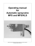
Operating Manual
for
Automatic sprayvalve
KA-2 / GT
KA-2 / GT, round spray
with clamp (option)
KA-2 / GT, flat spray
with clamp (option)
Read this manual carefully before installing, operating or servicing this equipment.
Keep always handy for further use.
1 Introduction
The automatic spray valve KA-2 / GT is designed and constructed for finest application of thin materials
f.i. release agents, colours or other fluids of low viscosity. Depending on air cap this spray valve sprays
in flat- or roundspray. Depending on viscosity of fluid, the application can be adjusted individually via
nozzle dimension, atomizing air pressure and material pressure. The supply of atomizing air, control air
and material should be done via three hoses. Spray valves are precision tools. Always keep clean and
observe minimum instructions to maintain a long usefull life of the valve.
2 Safety
2.1 Duties of the user
•
The user must read this service manual carefully before performing any operations.
•
Application and service operations should not be carried out if the user is not absolutely sure of
the purpose and consequence of the operations.
2.2 Definitive Use
The automatic spray valve KA-2 / GT is a pneumatically controlled spray valve; It is suitable for
sprayable materials. It is not suitable for spraying aggressive or heated materials. In case of doubt,
contact the manufacturer.
2.3 Warning against danger
This operating manual warns users of operations which may put their health at risk. The warnings are
indicated by combinations of text and symbols corresponding to the different danger classes.
WARNING!
Signs a possible dangerous situation.
If you don´t avoid, death or severe injuries can follow.
CAUTION!
Indicates a situation which may be dangerous.
Failure to heed the caution may result in personal injury. This indication is also used where material
damage is possible.
IMPORTANT!
Indicates tips for usage and other helpful information.
3 Function Description
The spray valve KA-2 / GT is pneumatically controlled: air open; spring return.
The spraying material is to be fed to the valve via pressure tank or pump. The separate controlled
atomizing air atomizes the material to a spray jet. Depending on mounted air cap valve sprays a flat- or
roundspray jet.
4 Installation
The KA-2 / GT can be installed in any position. The use of clamp (16) is recommended. Distance to
spraying surface varies width of application. Vibrations of the valve caused by fast intermitting cycles
require solid and massive installation. Vibration of the equipped machine to the valve should be limited
as far as possible.
4.1 Hose connection
Connect hoses for atomizing air and control air seperately to control valves (pressure reducers and
solenoids). Then fluidhose to material pressure tank or other means of feeding as under:
•
atomizing air Z (5) (hose blue):
Î
to 2/2 way solenoid
•
control air S (5) (hose black):
Î
to 3/2 way solenoid
•
fluid M (5) (hose transparent):
Î
to feeding device
Connections (5) can either be mounted alternatively on the upper side or the rear side of the valve.
Connection threads not used must be closed by lock screws using f.i. "Loctite no. 221".
Before Starting:
•
•
When connecting the pressure hoses to the spray valve, ensure that all the connection screws
are tight.
Follow the application notes of the spraying material manufacturer.
4.2 Operating instructions
CAUTION!
Never point the spray valve against persons. Wearing eye protection is strongly recommended.
Spraying procedures cause noises depending on the used pressure. If necessary, wearing of
ear protection is recommend.
WARNING!
Danger caused by combustible and noxious spraying material. Safety instructions on fluid can
and material data of fluid manufacturer must definitly be observed.
Do not smoke when spraying paints or solvents which have combustible properties. All electrical
installations within the spraying area must be explosionproof. Observe working safety regulations in
respect of protective clothing (masks, clothing, ear protection, etc.)
The valve KA-2 / GT needs 3 - 6 bar pressure for control air. The atomizing air should be 0,5 - 6 bar.
The maximum material pressure is 3 bar. If higher material pressure is necessary, please observe the
regulations of the professional/trade association having liability for industrial safety and insurance.
When you are certain, that fluid pressure stands up to the nozzle, actuate 2/2 way solenoid for
atomizing air. After that actuate 3/2 way solenoid for control air. This way you receive socalled "pre-air"
prior to opening fluid flow. After each cycle solenoids are to be actuated in reverse order, so you will still
have "purging-air" after needle has closed nozzle and fluid flow was stopped. This prevents fluid to form
out drops instead of being atomized. Set working pressure of atomizing air and fluid pressure according
to required spray droplet sizes. Two seperate pressure reducers must be available, if fluid is fed via
pressure tank.
Standard version of valve has flat spray air cap. If round spray cone jet is required, install round spray
air cap. Flat spray air cap can be positioned for horizontal, vertical or any in between position of jet.
Depending on viscosity of fluid, different nozzle diameters are available in 0,2 / 0,3 / 0,5 / 0,8 / 1,0 / 1,2
/ 1,5 / 2,0 and 2,5mm Ø.
IMPORTANT!
Fluid flow can be regulated with regulating screw (9).
turn right
: less fluid flow
turn left
: more fluid flow
IMPORTANT!
Wrong handling can damage nozzle and needle. Reduce fluid flow (clockwise turn of
regulating screw) only when fluid flows throught nozzle. After fluid flow is nil, never turn
regulating screw (9) further right.
For longer working interruptions and if the fluid is under pressure, it can stay in valve.
5 Repair and Maintenance
Before starting maintenance or repair work, ensure that all air operated tools are disconnected from the
air supply.
WARNING!
Danger caused by combustible and noxious spraying material. Safety instructions on fluid can
and material data of fluid manufacturer must definitly be observed.
WARNING!
Before opening the spray valve it has to be disconnected from the air and fluid
supply. Otherwise ejected elements can cause danger.
These spray valves are high precision tools. Always keep clean and observe minimum instructions to
maintain a long and useful life of valve.
We recommend lubricating moveable parts regularly, and greasing threads, especially the nozzle
threads, when replacing or cleaning the nozzle.
5.1 Cleaning
To clean valve, spray solvent until pure solvent leaves nozzle. Do not submerge entire valve in solvent.
At longer working interruptions it is advisable to clean air cap and nozzle by putting these parts only into
solvent. If necessary use a soft brush. Moving parts and threads should alway be greased slightly.
The spray valve should be cleaned using an appropiate thinner. To clean small drill holes, use our
special nozzle cleaning needles.
5.2 Trouble shooting
•
•
•
If seal (6) is worn, exchange this gasket removing needle (see "Changing nozzle set" /
"Changing needle gasket").
If drops form on the nozzle, either needle or nozzle is worn out and should be replaced. Or
needle is not closing properly f.i. because particle residues within nozzle.
If there is an uneven or not steady spray jet, make sure that nozzle is screwed in tight. Other
reason could also be dirt residue within air cap.
5.3 Changing the nozzle set
IMPORTANT!
Nozzles, gaskets and gasket seats can be damaged. Do not use metallical aid to remove and
insert those parts.
A nozzle set includes needle (7), nozzle (2) and air cap (1 or 1.1).
If nozzle size is to be changed, always change all these three parts. Change the complete set also
when only one of the parts is defect.
•
•
•
•
Take off closing plate (11) by unscrewing screws (13).
Pull out needle (7) and needle spring (8).
Take off air cap (1.0 or 1.1) after unscrewing collar ring (3).
Screw out nozzle (2) with wrench, size SW 6. Before unscrewing nozzle, please observe that
needle is never under spring pressure.
Reassemble in reverse order.
To prevent damage to the needle seat during replacement, the needle (7) must only be inserted into
firmly installed nozzle.
5.4 Changing needle gasket
After pulling out needle (7) (see "Changing the nozzle set"), needle gasket (6) can be taken out of the
valve body by means of using a pointed object. Re-assemble by laying the new gasket into the provided
slot.
6 Sparepartslist
draw.-no.
1.0
1.1
2
3
4
4.1
5
6
7
7.1
8
9
10
11
12
13
14
15
16
part no.
*
*
*
410028
510027
640006
220089
640026
*
640366
820017
610230
640000
510028
610021
610052
910014
610042
910015
Qty.
1
1
1
1
1
1
3
1
1
1
1
1
3
1
3
3
1
2
1
Description
air cap, flat spray (part no. see overleef)
air cap, round spray (part no. see overleef)
nozzle, stainless steel (part no. see overleef)
collar ring
main body, stainless steel
o-ring
connection M5
o-ring
needle, stainless steel, complete (part no. see overleef)
o-ring
needle spring
regulating screw, 8 x 13, M6 x 0,5, version GT
o-ring
closing plate, stainless steel
lock screw
mounting screw
clamp
mounting screw
clamp, complete
* part. no. see page 8.
When ordering nozzles, needles and air caps, please indicate nozzle dimension.
Available dimensions: 0,2 / 0,3 / 0,5 / 0,8 / 1,0 / 1,2 / 1,5 / 2,0 and 2,5mm ∅
If nozzle size is to be changed, always change all these three parts. Change the complete set also
when only one of the parts is defect.
7 Technical data
measurements:
with air cap, flat spray
with air cap, round spray
weight
air consumption
pressure for control air
pressure for atomizing air
material pressure
= 42mm length x 25mm x 25mm (without connections)
= 39mm length x 25mm x 25mm (without connections)
= 140g (with clamp 185g)
= 103ltr. (at 3 bar, 0,5mm nozzle and 2m hose)
= 3 – 6 bar
= 0,5 – 6 bar
= max. 3 bar
Special designs on request. Technical alterations reserved. August 2000
8 Manufacturer declaration
The spray valve KA-2 / GT were constructed and produced by
ALFRED SCHÜTZE Apparatebau GmbH, Hannoversche Straße 69-71, 28309 Bremen-Germany
in accordance with the guidelines and standards of DIN EN 292. This spray valve can be combined with
other modules or machines, which comply to DIN EN 292, without limiting the conformity.
Place
Bremen
Date
25.08.2000
Signature of manufacturer
6.1 part no. of needles, nozzles and air caps
*needle
draw no.
7
7
7
7
7
7
7
7
*nozzle
part no.
110155
110156
110157
110158
110159
110160
110161
110162
Description
0,2/0,3mm
0,5mm
0,8mm
1,0mm
1,2mm
1,5mm
2,0mm
2,5mm
*air cap / flat spray 45°
draw no. part no.
1.0
310038
1.0
310039
Description
for nozzle 0,2 - 1,0mm
for nozzle 1,2 - 1,8mm
* air cap / flat spray 60° (standard)
draw no.
1.0
1.0
1.0
1.0
part no.
310032
310033
310079
310090
Description
for nozzle 0,2 - 1,0mm
for nozzle 1,2 - 1,8mm
for nozzle 2,0mm
for nozzle 2,5mm
* air cap / flat spray 90°
draw no.
1.0
1.0
1.0
1.0
part no.
310036
310037
310166
310167
Description
for nozzle 0,2 - 1,0mm
for nozzle 1,2 - 1,8mm
for nozzle 2,0mm
for nozzle 2,5mm
* air cap / round spray 15°
draw no.
1.1
1.1
1.1
1.1
part no.
310034
310035
310080
310091
Description
for nozzle 0,2 - 1,0mm
for nozzle 1,2 - 1,8mm
for nozzle 2,0mm
for nozzle 2,5mm
draw no.
2
2
2
2
2
2
2
2
2
part no.
210110
210111
210112
210113
210114
210115
210116
210117
210118
Description
0,2mm
0,3mm
0,5mm
0,8mm
1,0mm
1,2mm
1,5mm
2,0mm
2,5mm