1
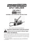
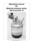
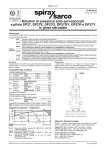
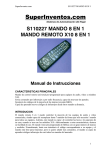
Operating Manual
for
extrusion valve
MMKD-30 KV/LV
Read this manual carefully before installing, operating or servicing this equipment.
Keep always handy for further use.
1 Introducion
The extrusion valves of series MMKD 30 KV/LV are very fast acting valves for continuous or
intermitted use. They are suitable for the application of glues, adhesives, oils and sealing compounds.
The extreme short control air distance, reached through the directly mounted 3/2 way solenoid valve
and the integrated control bold, gives this valve very fast and exact needle intermission cycles.
With the long nozzles (LV) the valves can be sloped to each other such to achieve narrow no zzle
distances. Depending on nozzle dimension and material pressure, fluids of different viscosities can be
applied. Extrusion valves are precision tools. Always keep clean and observe minimum instructions to
maintain a long useful life of the valve.
2 Safety
2.1 Duties of the user
•
The user must read this service manual carefully before performing any operations.
•
Application and service operations should not be carried out if the user is not absolutely sure of
the purpose and consequence of the operations.
2.2 Definitive use
The extrusion valve MMKD-30 KV/LV is a pneumatically controlled needle valve. It is suitable for
application of fluids, especially glues and adhesives, continuously or intermittent use. They are not
suitable for spraying aggressive fluids, like acids, alkaline solutions, cleaning agents, chemicals. When
you are not sure, if your fluid is suitable for spraying please contact the manufacturer.
2.3 Warning against danger
This operating manual warns users of operations which may put their health at risk. The warnings are
indicated by combinations of text and symbols corresponding to the different danger classes.
WARNING !
Signs a possible danger situation. If you don´t avoid, death or severe injuries can follow.
CAUTION !
Indicates a situation which may be dangerous. Failure to heed the caution may result in personal injury.
This indication is also used where material damage is possible.
IMPORTANT !
Indicates tips for usage and other helpful information.
3 Functional description
The extrusion valve MMKD-30 is a pneumatically controlled valve for application of fluids as f.i. glues,
adhesives, fats, colours, oils etc. The supply of fluid is to be obtained via pressure tank or pump. The
MMKD-30 has an extrusion jet (without atomizing air). The extreme short control air distance, reached
throw the direct mounted 3/2-way solenoid valve (15.0.0), gives this valve very fast and exact needle
intermission cycles up to 40 - 50 cycles per second. The piston receives alternately air pressure. When
control air is swiched off, a spring close the needle into the nozzle. This spring is designed for material
pressures up to 35 bar. For material pressures more than 35 bar a stronger spring is needed.
Operation of control air throw the direct mounted 3/2-way solenoid valve (15.0.0).
4 Installation and opening operations
The MMKD-30 valve can be installed in any position. Vibrations of the valve caused by fast intermitting
cycles require solid and massive installation. For solid attachment the valve body (4.1.0) is equipped
with two drill-holes (M 5 thread). Vibration of the equipped machine to the valve should be limited as far
as possible.
4.1 Hose connection
Connect hoses (not included) for control air and material as follows:
1. Hose for control air to connection M5 (draw.-no.: 21.0.0)
2. Hose for material to connection 1/4" (22.2.0)
4.2 Operating instructions
CAUTION !
Never point the spray jet against persons. Wearing eye protection is strongly
recommended. Spraying procedures cause noises depending on the used pressure.
If necessary, wearing of ear protection is recommend.
WARNING !
Danger caused by combustible and noxious spraying material. Safety instructions on fluid pot
and material data of fluid manufacturer must definitly be observed.
The extrusion valve MMKD-30 KV/LV is working with a control air pressure of 6 bar (up to material
pressures of 50 bar). When using more than 50 bar material pressure, a control air pressur e of 8 bar is
required. The material pressure should be between 1 - 100 bar (maximum). For material pressures
more than 35 bar a stronger spring is needed. If high material pressures are required, please observe
in any case the safety regulations of the employee´s compensation departments.
The valve can apply the fluid in contact as well as in non-contact to the surface. Intermittend use as
well as continuous use is possible.
The travel of needle is giving way to fluid as adjusted by the regulating knob (9.1.2). Turning this knob
in
anticlockwise turn
: more fluid
clockwise turn
: less fluid
One revolution of regulating knob (9.1.2) gives 0,5 mm more or less stroke. Maximum stroke is 6 mm.
Do not over-tight the regulating knob. In this case the o-ring (9.3.2) can´t seal the lock (9.2.2).
IMPORTANT !
The maximum fluid outlet is already reached, when no further ratchets are noticeable. Do not
Turn the regulating knob (9.1.2) in anticlockwise turn any further.
IMPORTANT !
To avoid damages to nozzle and needle, adjust decrease of fluid flow (turning regulating knob
9.1.2 clockwise) only when fluid is emitted from the nozzle. This is the only way to observe
the steady reduction of fluid flow until an absolute stop of fluid. Going on to turn the regulating
knob clockwise would at once push the needle into the nozzle to such an extent that both parts
could be damaged. This applies expecially to valves where needle regulation is execute by
hexagon key (special design, not shown in sectional drawing)
It is harmless to leave fluid within the valve (no connection to outside air), if system stays under
pressure.
5 Repair and Maintenance
Before starting maintenance or repair work, ensure that all air operated tools are disconnected from the
air supply.
WARNING !
Danger caused by combustible and noxious spraying material. Safety instructions on fluid can
and material data of fluid manufacturer must definitly be observed.
WARNING !
Before opening the spray valve it has to be disconnected from the air and fluid supply.
Otherwise ejected elements can cause danger.
The extrusion valves of series MMKD-30 KV/LV are high precision tools. Always keep clean and
observe minimum instructions to maintain a long and useful life of valve. We recommend lubricating
moveable parts regularly, and greasing threads, especially the nozzle threads, when replacing or
cleaning the nozzle.
It is recommended to use clean and filtered application fluids only. Control air should be slightly oiled.
5.1 Cleaning
To clean valve, spray solvent until pure solvent leaves the nozzle. Do not submerge entire valve in
solvent. At longer working interruptions it is advisable to clean needle and nozzle by putting these parts
only into solvent. If necessary use soft brush. Moving parts and threads should always be greased
slightly. The valve should be cleaned using an appropiate thinner. To clean small drill holes, use our
special nozzle cleaning needles.
5.2 Possible case of failure: Needle sticks
1)
2)
3)
4)
5)
6)
Check, if current on solenoid valve (slight click noise).
Check, if sufficient control air pressure is supplied (at least 6 bar).
Check, if bolt (12.0.0) moves. Air-release holes on under-side of valve must give off air
alternately. Noise control: metallic click noise of rear piston (12.1.0) on lock screw (11.1.0).
Check, if o-ring (6.2.0) or o-ring (7.4.0) are defect.
Check, if needle (7.0.0) is sticked together within retainer (6.0.0).
Check, if minimum of travel of needle is set.
5.3 Changing bolt (12.0.0)
Disconnect all connections from air pressure and material pressure supply. Open lock screw (11.1.0).
Spring pressure of spring (10.1.0) brings the bolt (12.0.0) out of the valve body. Replace bolt (12.0.0)
only with new gaskets and o-rings.
Re-assemble: First put the spring (10.1.0) in valve body. After this put front bolt (12.4.0), rear piston
(12.1.0) and lock screw (11.1.0) in valve body in this order and fix all parts tight.
5.4 Changing needle (7.0.0) and nozzle (2.1.0)
Unscrew ratchet assembly (9.0.2). Take out needle spring (8.1.0) and pull out needle (7.0.0) on back
side of needle piston by using a flat tong. Unscrew nozzle (2.1.0) with wrench SW 10. Re-assemble
new parts in reverse order slightly greased. It is not recommended to use old needles and nozzles
because even slightly damaged needle shafts would immediately cause leakage in gaskets.
5.5 Changing retainer (6.0.0)
IMPORTANT !
Do not use metallical aid to remove and insert gaskets and gasket seats !
Gaskets and gaskets seats can be damaged.
Unscrew ratchet assembly (9.0.2). Take out needle spring (8.1.0) and pull out needle (7.0.0) on back
side of needle piston by using a flat tong. Then using a screwdriver loosen retainer (6.0.0) till end of
thread. As retainer can not go through the thread of valve body by itself because of o-ring (5.3.0), it has
to be carefully pushed through be means of a thin metal sheet of 0,5 - 1,0 mm placed between gun
body recess and retainer. After passing thread retainer is accessible for taking out of housing.
5.6 Replacing new gaskets
IMPORTANT !
Do not use metallical aid to remove and insert gaskets and gasket seats !
Gaskets and gaskets seats can be damaged.
In case a new retainer (6.0.0) is not available to be replaced as a complete unit, the use d retainer has
to be cleaned thoroughly especially the o-ring groove and seats. These should also be greased slightly.
O-ring (6.2.0) is to be placed first into ground of the rear retainer bore. O-ring (5.3.0) then into the outer
groove. Mounting the gasket on the “fluid side” first place o-ring (5.2.0) into the front retainer bore.
After that insert gasket (5.1.0) into the center of o-ring. The shaped gasket (5.1.0) is not symetrical.
The somewhat wider opening must be positioned to point to the front of spray valve i.e. after assemling
retainer in direction “nozzle”. When inserting o-rings and gaskets, do not use any sharp or pointed
matallic implements. Mainly the gasket as a very precise and sensitive component is not able to stand
impacts. Completed retainer (6.0.0) slightly greased then is put back into housing and without turning
movement by means of a screw driver is to be carefully pushed through housing thread observing
outer o-ring (5.3.0). Lastly screw retainer into housing thread (tighten only slightly).
MMKD-30 KV
17
7
ca. 125
22
30
18
16
ca. 87
40
M 5
t = 15mm
ca. 150
MMKD-30 LV
30
18
t = 15mm
ca. 168
16
ca. 87
40
40
M 5
17
7
ca. 143
22.2.0
4.1.0
2.1.0LV
21.0.0
15.0.0
2.1.0KV
5.4.0
14.0.0
14.1.0
5.1.0
6.1.0
10.1.0
7.1.0
12.1.0
2x12.3.0
6.0.0
6.2.0
12.4.0
4x14.2.0
5.3.0
7.4.0
8.1.0
2x12.2.0
7.0.0
12.0.0
11.1.0
9.0.2
6. Sparepartslist
draw.-no.:
2.1.0
4.1.0
5.0.0
5.1.0
5.3.0
5.4.0
6.0.0
6.1.0
6.2.0
7.0.0
7.4.0
8.1.0
8.1.0
9.0.2
9.1.2
9.2.2
9.3.2
9.4.2
9.5.2
10.1.0
11.1.0
12.0.0
12.1.0
12.2.0
12.3.0
12.4.0
13.1.0
14.0.0
14.1.0
14.2.0
15.0.0
21.0.0
22.2.0
part-no.
*
510040
640102
640004
640021
640101
810014
810013
640026
*
640001
820020
820024
900008
610093
220104
640027
320022
620017
820037
610097
800017
710009
640001
640028
320099
610096
320101
320100
640035
*
220089
220022
Qty.
1
1
1
1
1
1
1
1
1
1
1
1
1
1
1
1
1
1
1
1
1
1
1
2
2
1
1
1
1
4
1
1
1
Description
nozzle, stainless steel
valve body MMKD 30, complete
gasket set
Variseal 2,65 x 2,0 x 2,8mm
o-ring 6,07 x 1,78mm / viton
protecting cover, ø 10 x 6mm
retainer, complete, 11 x 21mm
retainer, 11 x 21mm
o-ring 2,90 x 1,78mm
needle, complete, tungsten carbide
o-ring 7,65 x 1,78 / Viton
spring 1,1 x 22mm (0 - 30 bar material pressure)
spring 1,2 x 21,5mm (30 - 100 bar material pressure)
ratchet assembly, complete, ø 15 x 45mm
regualting knob, ø 15 x 45mm
lock, wrench size 13 x 26mm
o-ring 4,47 x 1,78mm / Viton
straight pin, DIN 6325 1,5 x 8
circlip, DIN 6799 RA 2,3
spring 0,9 x 35mm
lock screw, Ø 15 x 8mm, with slit
bolt, complete
rear piston, Ø 10,8 x 8mm
o-ring 7,65 x 1,78 / Viton
Quad-ring 4,47 x 1,78 / Viton
front bolt, brass, Ø 7,8 x 41,5mm
screw DIN 417 M3 x 8
sleeve, complete
sleeve, brass, Ø 10,8 x 25mm
o-ring 8 x 1/ Viton
solenoid valve, with plug
connection M5
connection 1/4"
* Please find part-numbers on next pages.
When ordering needles and nozzles, please specify dimension.
Available dimensions: 0,2 / 0,3 / 0,4 / 0,5 / 0,6 / 0,7 / 0,8 / 1,0 / 1,2 / 1,5 / 2,0 mm ∅
6.1 part-numbers for nozzles, needles and solenoid valves
* nozzle, LV, stainless steel
draw.-no.
1.0
1.0
1.0
1.0
1.0
1.0
1.0
1.0
1.0
1.0
1.0
part-no.
210132
210133
210134
210102
210136
210137
210138
210139
210140
210141
210142
description
nozzle, LV, 0,2 mm, stainless steel
nozzle, LV, 0,3 mm, stainless steel
nozzle, LV, 0,4 mm, stainless steel
nozzle, LV, 0,5 mm, stainless steel
nozzle, LV, 0,6 mm, stainless steel
nozzle, LV, 0,7 mm, stainless steel
nozzle, LV, 0,8 mm, stainless steel
nozzle, LV, 1,0 mm, stainless steel
nozzle, LV, 1,2 mm, stainless steel
nozzle, LV, 1,5 mm, stainless steel
nozzle, LV, 2,0 mm, stainless steel
* nozzle, KV, stainless steel
draw.-no.
1.0
1.0
1.0
1.0
1.0
1.0
1.0
1.0
1.0
1.0
1.0
part-no.
210143
210144
210145
210146
210147
210148
210149
210150
210151
210152
210153
description
nozzle, KV, 0,2 mm, stainless steel
nozzle, KV, 0,3 mm, stainless steel
nozzle, KV, 0,4 mm, stainless steel
nozzle, KV, 0,5 mm, stainless steel
nozzle, KV, 0,6 mm, stainless steel
nozzle, KV, 0,7 mm, stainless steel
nozzle, KV, 0,8 mm, stainless steel
nozzle, KV, 1,0 mm, stainless steel
nozzle, KV, 1,2 mm, stainless steel
nozzle, KV, 1,5 mm, stainless steel
nozzle, KV, 2,0 mm, stainless steel
* needle, LV, tungsten carbide
draw.-no.
5.0
5.0
5.0
5.0
5.0
5.0
5.0
5.0
part-no.
110221
110222
110223
110224
110225
110227
110228
110229
description
needle, LV 0,2/0,3mm, complete
needle, LV 0,4mm, complete
needle, LV 0,5mm, complete
needle, LV 0,6/0,7mm, complete
needle, LV 0,8/1,0mm, complete
needle, LV 1,2mm, complete
needle, LV 1,5mm, complete
needle, LV 2,0mm, complete
*needle, KV, tungsten carbide
draw.-no
5.0
5.0
5.0
5.0
5.0
5.0
5.0
5.0
part-no.
110230
110231
110232
110233
110234
110235
110236
110237
description
needle, KV 0,2/0,3mm, complete
needle, KV 0,4mm, complete
needle, KV 0,5mm, complete
needle, KV 0,6/0,7mm, complete
needle, KV 0,8/1,0mm, complete
needle, KV 1,2mm, complete
needle, KV 1,5mm, complete
needle, KV 2,0mm, complete
*solenoid valve 3/2-way
draw.-no.
10.0
10.0
10.0
part-no.
150018
150019
150020
description
solenoid valve 24V / DC / 2,5W with plug
solenoid valve 110V / 50Hz / 1,5W with plug
solenoid valve 220V / 50Hz / 1,5W with plug
7. technical data
measurements:
LV-version
KV-version
weight
control aire pressure
material pressure
gaskets
= approx. 168mm x 15mm x ca. 87mm
= approx. 150mm x 15mm x ca. 87mm
= approx. 435 g
= minimum 6 bar, from 50 bar material pressure = 8 bar
= max. 100 bar
= Viton
Special designs on request. Technical alterations reserved. January 2003.
8. Manufacturer Declaration
The extrusion valves MMKD-30 LV/KV are constructed and produced by
ALFRED SCHÜTZE Apparatebau GmbH, Hannoversche Straße 69-71, 28309 Bremen – Germany
in accordance with the guidelines and standards of DIN EN 292. This spray valve can be combined
with other modules or machines, which comply to DIN EN 292, without limiting the conformity.
place
date
Bremen
03.02.2003
signature of manufacturer