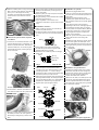
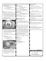
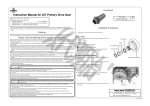
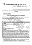
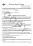
1
Instruction Manual for
Bore-Up Kit (174.5cc) for HONDA’s CRF150F
CO
:01−05−0101
Item No.
Applicable Model : Honda CRF 150F (Up to ‘05 models)
・Thank you for purchasing one of TAKEGAWA's products. Please strictly follow the following instructions in installing and using the products.
・Before fitting the products, please be sure to check the contents of the kit. Should you have any questions about the products, please kindly contact your
dealer.
Features
・This is a bore-up kit of a cylinder and a piston utilizing a normal cylinder head.
・A bore diameter has been enlarged from 63.5 mm to 67.0 mm, and displacement from 156.8 cc to 174.5 cc.
・As this kit goes well with a MUKUNI VM26 carburetor kit and our TAKEGAWA’s cam shaft, it can be expected that this kit will work to further power up your
motorcylcle.
Please read the following before starting the installation
!Caution on the fuel!
This product is so designed to achieve a higher compression ratio than stock engines. As for the fuel, high-octane gasoline should always be used.
In case regular gasoline is used, abnormal combusiton will take place, and the engine cannot achieve its original performance. Moreover, the piston likely
will be damaged, leading to a serious failure of a motorcycle. Before installing this kit, make sure that no regular gasoline remains in the fuel tank. In case
regular gasoline remains in the fuel tank, do replace it with high-octane gasoline.
PY
!Safety information on spark plugs!
Be sure to replace a spark plug with a hot-type spark plug DPR9EA-9(NGK) or the one with a higher thermal value. Determine the heat value of a spark
plug depending on how much it is burnt.
・We do not take any responsibility for any accident or damage whatsoever arising from the use of the products not in conformity with the instructions in
the manual.
・We shall be held free from any responsibility or compensation whatsoever for any glitch in the parts other than ours if the glitch takes place after the installation and use of the products.
・You are kindly requested not to contact us about the combination of our products with other manufacturers’.
・This kit is designed for exclusive use in the above-mentioned applicable model name. This kit cannot be mounted on other types of motorcycles.
・Installation of this kit requires engine removal. Please strictly follow HONDA’s genuine service manual for your vehicle to do the work correctly.
・Prepare right tools to do the work, strictly following the installation procedures with great caution. Besides, this instruction manual, as well as HONDA’s
genuine service manual, is prepared for those persons who have basic skills and knowledge. Therefore, we recommend those who are technichally inexperienced or do not have sufficient tools to ask a technically-reliable specialist shop for the work.
・Never fail to do the shake-down.
・The installaiton of this product increases the heat release value of the engine, set off by the increase in power, which is unsuitable for long hours of
high-load driving.
・Some of bolts, nuts, dowel pins and packings will be reused. But always replace the severely worn or damaged parts with new ones.
The following show the envisioned possibility of injuries to human bodies or property damages as a result of disregarding the following
Caution cautions.
・Work only when the engine and the muffler are cool. (Otherwise, you will burn yourself.)
・Prepare right tools for the work. (Otherwise, parts will be damaged or you will suffer injuries.)
・Always use a torque wrench to screw bolts and nuts to the specified torque. (Improper torque could cause these parts to get damaged or fall off.)
・As some products and frames have sharp-pointed or protruding portions, please work with your hands protected.
(Otherwise, you will suffer injuries.)
・Before riding, always check every section for slack in parts like screws. If you find slack ones, screw them securely up to the specified torque.
(Or improper torque may cause parts to come off.)
・Check gaskets and packings carefully for wear or damage. Always replace the worn or damaged parts with new ones.
The following show the envisioned possibility of human death or serious injuries to human bodies as a result of disregarding the
Warning following cautions.
・Always start the engine in a well-ventilated place, and do not start it in an airtight place. (Otherwise, you will suffer from carbon monoxide poisoning.)
・When you notice something abnormal with your motorcycle while riding down a road, immediately stop riding and park your motorcyle in a safe place. (Otherwise, the abnormaility could lead to an accident.)
・Before doing the work, place the motorcycle on level ground to stablize the position of your motorcycle for safety's sake.
(Otherwise, your motorcycle could overturn and injure you while you are working.)
・Check or perform maintenance of parts correctly according to the procedures in the instruction manual or a service manual.
(Improper checking or maintenance could lead to an accident.)
・If you find damaged parts when checking and performing maintenance of your motorcycle, do not use these parts any longer, and replace them with new ones. The continued use of these damaged parts could lead to an accident.)
◎ Please be informed that, because of improvement in performance, design changes, and cost increase, the product specifications and prices are subject to change without prior notice.
◎ We shall be held harmless against any claim whatsoever arising out of use of the products in racing and the like.
◎ This manual should be retained for future reference.
Mar./25/’
05
-1-
∼ Kit Contents ∼
1
5
CO
No.
1
2
3
4
5
6
7
8
9
2
6
3
7
4
8
9
Part Name
Piston φ67
Piston ring set
Piston pin φ15x48
Piston pin circlips φ15
Cylinder
Cylinder head gasket
Cylinder gasket
Cam sprocket cover gasket
Tensioner lifter gasket
Qty
1
1
1
2
1
1
1
1
1
PY
∼ Installation Procedures ∼
◇ As the engine needs to be removed during the work, secure the vehicle on a stand on level safe ground. Do the following work only when the engine
and the muffler are cool.
●Removal of Engine and Other Parts
●Removal of Cam Sprocket
◇ Referring to Honda’s service manual, remove
or disconnect the following parts.
・Seat / left and right side cover
・Fuel tank / fuel hose
・Wires to the engine
・Spark plug cap
・Clutch cable
・Crankcase breather tube
◇Remove tappet hole caps / O-rings and cam sprocket cover / O-ring on both intake and
exhaust sides. Completely wipe off gaskets with
a scraper and the like, if any remains on the
cylinder head or cam sprocket cover.
・Drive sprocket
・Exhaust pipe
・Manifold / Carburetor
◇ Unscrew bolts / nuts which are mounting the
engine, and then demount the engine from the
frame. Be careful not to scratch the frame, etc.
●Removal of Spark Plug
◇ Remove a spark plug.
◇ Rotate the flywheel counterclockwise to be at
TDC (Top Dead Center) on the compression stroke. This means that a “T" mark on the
flywheel is aligned with an alignment mark on
the crankcase cover and that a rocker arm is loose or shaky.)
Tappet hole cap
Cam sprocket cover
◇Remove a timing hole cap and crank shaft hole cap.
Timing hole cap
◇Holding the flywheel, loosen a cam sprocket bolt.
◇Remove the cam sprocket bolt, detach the cam
sprocket from the cam shaft, and detach the cam sprocket from the cam chain.
Crank shaft hole cap
-2-
Mar./25/’
05
◇ Remove a sealing screw / O-ring, and lock the
lifter on the cam chain tensioner. (The lifter will
lock if you turn the stopper all the way
clockwise.) Unscrew bolts and washers to
remove the cam chain tensioner from the
cylinder.
◇ Remove the cylinder, and take off and check two
dowel pins for abnormality. If nothing wrong is found, reuse them.
◇ Detach a piston pin circlip and pull out the piston
pin to demount the piston.
※ Plug the opening on the crankcase with a waste
cloth not to get a circlip in it.
◇ Wipe off gaskets on the surface of the
crankcase to mate with a cylinder with a scraper
if any.
CO
Sealing screw
● Installation of Piston
◇Attach a piston pin circlip to one of the two pin holes on the piston of the kit.
※ Arrange the position of the end-gap of the piston
pin circlip not to be on the notch of the piston pin
hole.
Bolts
Circlip
●Removal of Cylinder Head, Cylinder
Piston
and Piston.
◇ Loosen the nuts / washers and bolts on the
cylinder head diagonally in a few steps, and
remove a cylinder head cover. Take off and check two dowel pins, an oil hole plug and
camshaft for abnormality. If nothing wrong is found, reuse them.
Notch
end- gap
◇ Attach piston rings of the kit to the piston.
Fix both the top and second rings with “RN”- stamped sides facing upwards.
※Be careful not to scratch the piston or damage piston rings.
Piston
Nuts
●Installation of Cylinder
◇ Remove the plugged waste cloth.
◇ Look into a cam chain hole and check that the
cam chain has not come off the sprocket on the
crank shaft.
◇ Degrease the mating surfaces of the
crankcase and cylinder with thinner and the like, and attach a dowel pin and cylinder gasket
of the kit.
◇ First clean the inside of the cylinder by degreasing it with thinner, and apply engine oil
and spread the oil evenly with your fingers.
◇ Fit the cylinder into the piston little by little with
fingers, being careful not to move the piston ring end gaps out of place. And place the
cylinder in the crankcase.
※ After the cylinder has been placed inside the
piston, pass the cam chain through the
cylinder.
◇Degrease the upper part of the cylinder, and fix
the cam chain guide, two dowel pins, and a cylinder head gasket of the kit. Fit the cam chain
guide right into the grooves in the cylinder and
the crankcase.
PY
Dowel pins
Gasket
Top ring
Second ring
Side rails
Expander
Pay attention to cross section as well.
Dowel Pins
◇Apply engine oil to the piston pin of the kit, the pin
hole on the piston, and the small end of the connecting rod. Then, attach the piston to the connecting rod with a “ △ ” mark on the top
surface of the piston pointing to the exhaust side,
and attach a piston pin circlip of the kit.
◇Apply engine oil to the piston rings and check that
each ring rotates smoothly. Do not align the piston
ring end gap with the piston pin or 90 degrees to
the piston pin. Space the ring end gaps 120
degrees apart. (See the figure below.)
Mark
Oil hole plug
Mark
Guide
●Installation of Cylinder Head
◇Degrease the mating surface of the cylinder with thinner. Pass the cam chain through the cylinder head, and then fix the cylinder head.
◇ Fix the cam chain tensioner slider to the
cylinder head with bolts / washers.
◇ Attach the cam shaft , two dowel pins and an
oil hole plug, apply liquid gasket to the clamp face for a cylinder head cover, and install it with a cam top of cam shaft pointing towards
the combustion chamber.
Top ring
Dowel pins
◇ Unscrew bolts / washers, and detach a cam
120°
chain tensioner slider from the cylinder head.
120°
Tensioner slider
120°
2nd ring
Oil hole plug
Bolt
Side rails
Expander
25mm
25mm
Pin direction
90°to the pin
◇Remove a cylinder head, and take off and check
two dowel pins and a cam chain guide for
abnormality. If nothing wrong is found, reuse them.
Piston
Liquid gasket application
-3-
Mar./25/’
05
◇ Loosely tighten 4 washers / nuts and 5 bolts.
◇Attach a timing hole cap and a crank shaft hole Tighten up nuts first diagonally in a few steps.
Specified torque: for cylinder head nut:
27 N・m (2.8 kgf・m)
for cylinder head bolt:
12 N・m (1.2 kgf・m)
cap.
Specified torque: for timing hole cap:
10 N・m (1.0 kgf・m)
for crankshaft hole cap:
8 N・m (0.8 kgf・m)
◇ Attach an O-ring and a gasket of the kit to the cam sprocket cover, and fix them to a cylinder ●Installation of Cam Sprocket
head with two bolts.
Specified torque: 9 N・m (0.9 kgf・m)
◇Fix the tappet hole cap / O-ring on both intake and
exhaust sides to the cylinder head.
Specified torque: 15 N・m (1.5 kgf・m)
CO
◇Check that a “T” mark on the flywheel is aligned
with an alignment mark on the crankcase cover.
◇Fix the cam sprocket to the cam chain, aligning
an “I” mark on the cam sprocket with the
cylinder head mating surface, and insert the c
am sprocket into the cam shaft. Holding the
flywheel, attach two bolts.
Specified torque: 12 N・m (1.2 kgf・m)
●Installation of Spark Plug
◇ Prepare a spark plug and fix it.
Specified torque: 18 N・m (1.8 kgf・m)
※ Replace a spark plug with a hot-type spark plug
DPR9EA-9(NGK) or the one with a higher thermal
value.
●Starting of Engine
1.About fuel
◇ Always use high-octane gasoline.
◇ Whenever regular gasoline is remaining in the
fuel tank, always replace it with high-octane gasoline
2.Checking of Every Section
◇ Check every section for slack in screws, nuts,
etc.
◇Make sure that engine oil is remaining in a
specified amount.
◇Drive the engine in a well-ventilated safe place
with great care. Leave the engine idling for a few minutes so engine oil gets circulated all around the engine.
◇ Check that there is n
◇ Check for any abnormality such as abnormal
sounds from the engine, oil leak from gaskets,
and exhaust-air leak from a joint on an exhaust
pipe.
◇ Stop the engine, and after the engine has
become cool enough, check every section again
for slack in screws, nuts, etc.
PY
●Installation of Engine and Other Parts
◇With reference to HONDA’s genuine service manual, place the engine in the frame with care ◇Make sure that a cam chain tensioner's lifter is
locked. Attach a gasket of the kit to the cam chain tensioner, and install it to the cylinder with
two bolts / washers. Unlock the lifter by turning
a cam chain tensioner's stopper
counterclockwise.
Attach a cam chain tensioner's sealing screw /
O-ring.
Specified torque:
for tensioner fixing bolt:
12 N・m (1.2 kgf・m)
for ceiling screw:
4 N・m (0.4 kgf・m)
Sealing screw
not to scratch the frame or other parts.
Then temporarily tighten mounting bolts / nuts.
Insert a drive sprocket, already attached with a
drive chain, into the counter shaft. If it is hard to do so, insert it while shaking the engine lightly.
◇With moderate slack on the drive chain, fully tighten the temporarily-tightened mounting bolts
/ nuts. And fix the drive sprocket.
◇ Referring to Honda’s genuine service manual, 3.About running-in
◇ For the purpose of shakedown of the piston and cylinder, never fail to run in the vehicle for
about 100 km at the reduced engine
revolutions, avoiding the sudden acceleration.
reinstall or connect the removed or disconnected
parts.
・Exhaust pipe
・Manifold / Carburetor
・Wires to the engine
・Spark plug cap
・Clutch cables
・Crankcase breather tube
・Seat / left and right side covers
・Fuel tank / fuel hose
Bolt
◇ Rotate the crank shaft clockwise, and align again the "T" mark on the flywheel with the alignment mark on the crankcase cover.
At this point, check that the "I" mark on the cam
sprocket is still aligned with the mating surface
of the cylinder head.
3-5-16 Nishikiorihigashi Tondabayashi
Osaka Japan
TEL : 81-721-25-1357
FAX : 81-721-24-5059
URL : http://www.takegawa.co.jp
-4-
Mar./25/’
05