1
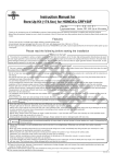
Instruction Manual for Cam Shaft Kit
(Exclusive for Bore-Up)
CO
Item No. 01−08−0381
Applicable models
Frame Nos
SL230 :MD33-1000001∼
FTR :MC34-1000001∼
XLR125R
:JD16-1000001∼
CRF150F (Up to ‘05 models)
Thank you for purchasing one of our TAKEGAWA’s products. Please strictly follow the following instructions in installing and using the kit. Before fitting the
kit, please be sure to check the contents of the kit. Should you have any questions about the kit, please kindly contact your dealer.
Please read the following instructions before installation.
◎ We do not take any responsibility for any accident or damage whatsoever arising from the use of the kit not in conformity with the instructions in the manual.
◎ We shall be held free from any responsibility or compensation whatsoever for any glitch in parts other than ours if the glitch takes place after the installation and use of this kit.
◎ If you make alterations to the product, we shall be held free from any guarantee of the kit.
◎ You are kindly requested not to contact us about the combination of our kit with other manufacturers'.
◎ This kit is designed for exclusive use in vehicles equipped with a TAKEGAWA’s bore-up piston kit (Item Nos:01-02-0911 / 01-02-0912 / 01-02-092).
PY
◎This kit is designed for exclusive use in the above-mentioned types of motorcycles and frame numbers only. Please take note that this kit cannot be mounted on other types of motorcycles.
◎Installation of this kit requires engine removal and mounting. Please perform the installation work correctly with reference to the relevant HONDA genuine
parts service manual.
◎ In installing, please work with enough care following the installation procedures. Besides, this instruction manual, as well as a HONDA genuine parts service manual, is written for persons who have acquired basic skills and knowledge in tuning. We recommend those who are technically unskilled or without enough tools to ask a specialist shop for installation work.
◎ Some of bolts, nuts, and dowel pins will be reused. However, be sure to replace worn-down or severely-damaged ones with new ones.
◎ Fuel must be super-unleaded gasoline.
CAUTION
The following show the envisioned possibility of injuries to human bodies and property damage as a result of disregarding the
following cautions.
・Please try to drive your motorcycle at legal speed, abiding by the laws.
・Work only when the engine and the muffler are cool. (Otherwise, you will burn yourself.)
・Prepare right tools for the work, and do the job correctly. (Otherwise, improper work could cause breakage of parts or injuries to yourself.)
・Always use a torque wrench to screw bolts and nuts tight and securely to the specified torque. (Improper torque could cause these parts to get damaged or fall off.)
・As some products and frames have sharp-pointed or protruding portions, please work with your hands protected. (Otherwise, you will suffer injuries.)
・Before riding, always check every section for slack in parts like screws. If you find slack ones, screw them securely up to the specified torque.
(Or improper torque may cause parts to come off.)
・Always use new gaskets and packings. Besides, check carefully those parts to be reused, and in case wear or damage is detected, always replace
them with new ones.
The following show the envisioned possibility of human death or serious injuries to human bodies as a result of disregarding the
WARNING following cautions.
・Always drive the engine in a well-ventilated place, and do not switch the engine on in an airtight place. (Otherwise, you will suffer from carbon monoxide poisoning.)
・When you notice something abnormal with your motorcycle while riding down a road, stop riding immediately and park your motorcyle in a safe place.
(Otherwise, the abnormaility could lead to an accident.)
・Before doing work, place the motorcycle on level ground to secure it for safety's sake. (Otherwise, your motorcycle could overturn and injure you while
you are working.)
・Check or perform maintenance of parts correctly according to the procedures in the instruction manual or a service manual. (Improper checking or maintence could lead to an accident.)
・If you find damaged parts when checking and performing maintenance, do not use these parts any longer, and replace them with new ones.
The continued use of these damaged parts as they are could lead to an accident.)
◎ Please be informed that, mainly because of improvement in performance, design changes, and cost increase, the product specifications and prices are
subject to change without prior notice.
◎ A defective product which we acknowledge is caused by product materials or defect in manufacturing will be repaired or replaced with a new one,
by us at our expense, if and when a claim is filed with us within one (1) month of your purchase. However, replacing of parts shall be made at users’ expenses. And we shall be held free from responsibility for any defect caused by improper installation or use.
◎ You are requested to keep this instruction manual until you discard this product.
-1-
Apr./27/’
06
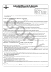
∼ Kit Contents ∼
CO
2
No
Parts Name
1 Cam shaft Comp.
2 Cam sprocket cover gasket
Qty
1
1
1
∼ Installation Procedures ∼
1. To replace a stock cam shaft, the engine need
to be removed from the frame.
During engine removal and mounting, make sure
the bike is secure on the sidestand.
※ Work only when the engine and the muffler are cool.
2. DEngine Removal
a. With reference to the service manual, remove
/ disconnect the following;
・Seat
・Side covers
・Fuel tank
・Negative terminal on the battery
・Drive sprocket
・Change pedal, or change pedal link
・Air suction pipe (if equipped)
・Carburetor
・Spark plug cap
・Skid plate (SL230)
・Exhaust pipe / muffler
・EAC generator 3P coupler
・Pulse generator / neutral switch 3Pcoupler
・Clutch cable
・Crankcase breather tube
・Starter motor cable
・Starter motor earth cable
・Starter motor
PY
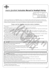
3. Stock Cam Shaft Removal
a. Remove two tappet hole caps, a crank shaft hole
cap, and a timing hole cap.
c. Rotate the crank shaft counterclockwise till a
“T” mark on the flywheel is aligned with the alignment mark on the crankcase cover. Then
check that it is at TDC (Top Dead Center) on the
compression stroke where you feel slackness
when you move the rocker arm by hand.
b. Unscrew two bolts on a cam sprocket cover, and remove the cam sprocket cover and the
gasket.
b. Place a jack or a suitable stand under the
engine to support it . Remove a cylinder head
hanger, front engine hanger plate, and rear
engine mounting bolts / nuts, and then dismount
the engine from the frame.
※ Be careful not to give scratches to the frame
or other parts.
d. Holding the flywheel tightly, loosen two cam sprocket bolts.
If some gasket chips remain on the surface, wipe
them out completely with a scraper or the like.
-2-
Apr./27/’
06
4. Cam Shaft Installation
CO
a. Check that the “T” mark on the flywheel is aligned
with the alignment mark on the crankcase cover.
Apply oil here
Oil hole
plug
Dowel pins
e. Unfasten a sealing screw on the cam chain tensioner, and rotate a stopper clockwise to lock the tensioner rod.
f. Unfasten bolts and nuts on the cylinder head
cover by rotating them clockwise in a few steps
diagonally, and then unfasten sealing
washers and cylinder head cover.
d. Fill up the oil pool in the cam with fresh engine
oil.
e. Check that a oil hole plug and two dowel pins
are fixed on the cylinder head.
PY
Engraved lines
Apply liquid packing to the mating surface of the cylinder head, and fix the cylinder head cover to the cylinder head.
The cam top should point
downwards.
g. Detach the cam chain from the cam sprocket to
remove it.
※Be careful not to drop the cam chain into the crankcase. Suspend it by a wire or the like.
b. After applying fresh engine oil to the bearings, install the cam shaft so that the engraved lines on
the cam sprocket are parallel to the mating
surfaces of the cylinder head and that the cam
top faces toward the combustion chamber.
h. Remove the loosened two bolts on the cam sprocket. Then fix the cam sprocket to a cam
shaft of the kit, and tighten the two cam sprocket
bolts temporarily.
c. After checking that the cam chain is fit in the timing sprocket of the crank shaft, fix the cam chain to the cam sprocket.
-3-
Apply engine oil to the threaded part and
the seating face.
f. Fix four sealing washers. Apply engine oil to the threaded parts and seating faces of four
cylinder head cover nuts and tighten them
temporarily. Then tighten four cylinder head cover bolts temporarily.
Apr./27/’
06
CO
Engraved lines
Tighten the cylinder head cover nuts first, and
then the cylinder head cover bolts. Tighten both
of them in several steps diagonally.
Specified torque: for cylinder head cover nuts
:27 N・m (2.8 kgf・m)
for cylinder head cover bolts
:12 N・m (1.2 kgf・m)
Upper surface of cylinder head
i. Give the crank shaft two turns counterclockwise
and align the “T” mark on the flywheel with the alignment mark on the left-side crank case. Then
check at this point that the engraved lines on the
cam sprocket are parallel to the upper surface of
the cylinder head.
PY
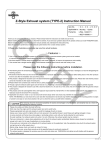
5. Valve Clearance
g. Holding the flywheel tight, fully tighten the
temporarily-tightened two cam sprocket bolts.
Specified torque:12 N・m (1.2 kgf・m)
Adjusting screw
Thickness gauge
Valve stem
a. After checking that it is at TDC (Top Dead Center)
on the compression stroke, place a thickness h. Rotate the stopper on the cam chain tensioner
counterclockwise to unlock the tensioner.
gauge between an adjusting screw and a valve
stem to measure its valve clearance.
Valve clearance
: 0.10 mm for both intake and exhaust
b. Install and tighten two tappet hole caps, a crank
shaft hole cap, a timing hole cap, and a sealing
screw of the cam chain tensioner.
Torque:
Tapet hole caps
:15 N・m (1.8 kgf・m)
Crank shaft hole cap
:8 N・m (0.8 kgf・m)
Timing hole cap
:10 N・m (1.0 kgf・m)
Sealing screw
:4 N・m (0.4 kgf・m)
Gasket
If you need to adjust the clearance, loosen the nut
and tighten the adjusting screw.
Fix the adjusting screw firmly, and tighten the nut.
Specified torque:14 N・m (1.4 kgf・m)
After tightening the nut, give the crank shaft two
counterclockwise turns to be at TDC again, and
check if the valve clearance is right. If the clearance is changed, adjust it again. Repeat the procedures until the right clearance is obtained.
-4-
c. Fix a gasket of the kit to the cam sprocket cover, and install the cover to the cylinder head.
Install and tighten two bolts.
Specified torque:10 N・m (1.0 kgf・m)
Apr./27/’
06
6. Engine Mounting
a. Set the engine onto the frame with care not to
give scratches to the frame and other parts.
Temporarily tighten the bolts and nuts for rear
engine mounting, front engine hanger plate, and cylinder head hanger.
7. Engine Starting
a. Check each section for slackness in the screws,
nuts, and so on.
b. Check that engine oil is in the specified amount.
CO
b. Put the drive sprocket, fixed with the drive chain, into the counter shaft. If it is hard to put
it in, insert it while shaking the engine lightly.
c. Moderately slacking the drive chain, tighten the
temporarily-tightened engine-mounting bolts and nuts in the following order:
Specified torque:
Rear upper engine mounting bolt/nut
:49 N・m (5.0 kgf・m)
Rear lower engine mounting bolt/nut
:49 N・m (5.0 kgf・m)
Front engine hanger plate bolt/nut :34 N・m (3.5 kgf・m)
Cylinder head hanger bolt / nut
:34 N・m (3.5 kgf・m)
d. Install a fixing plate of a drive sprocket, and tighten two bolts.
Specified torque:12 N・m (1.2 kgf・m)
e. Referring to the service manual, install the
following parts and and connect the following
cables:
・Starter motor
・Starter motor earth cable
・Starter motor cable
・Crankcase breather tube
・Clutch cable
・Pulse generator / neutral switch 3P
・coupler
・AC generator 3P coupler
・Exhaust pipe / muffler
・Skid plate (for SL230)
・Spark plug cap
・Carburetor
・Air suction pipe (if equipped)
・Change pedal, or change pedal link
・Drive sprocket
・Negative terminal on the battery
・Fuel tank
・Side covers
c. Start the engine in a well-ventilated safe place.
Leave the engine idling for about 5 minutes so engine oil gets circulated all around the engine.
d. Check for any abnormalily such as abnormal sounds from the engine, oil leakage from
gaskets, and slack in the screws and nuts.
PY
・Seat
3-5-16 Nishikiorihigashi Tondabayashi
Osaka Japan
TEL : 81-721-25-1357
FAX : 81-721-24-5059
URL : http://www.takegawa.co.jp
-5-
Apr./27/’
06