1
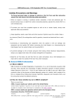
Operator's Manual
Operator's Manual
EC CONFORMITY
Vetronix Corporation certifies that the Nissan CONSULT-II kit complies with the following
requirements as called out in the 89/336/EEC Directive for the European Community. Upon
request, Vetronix Corporation will supply a copy of the Declaration of Conformity.
Product Specifications (Standards)
CISPR 22:1993/EN 55022 Edition 1 Class A
IEC1000-4-2:1995/EN50082-1:1992
IEC1000-4-3:1995/EN50082-1:1992
IEC1000-4-4:1995/EN50082-1:1992
Copyright © 1999
Vetronix Corporation
Printed in USA 3/99
Manual P/N 02002606-005
TABLE OF CONTENTS
INTRODUCTION.............................................................................................................................................................i
CONSULT-II OPERATOR'S MANUAL ....................................................................................................................i
PROGRAM CARD OPERATOR'S MANUALS ........................................................................................................i
SCREEN DISPLAYS IN THIS MANUAL..................................................................................................................i
LOCATION OF VEHICLE ECUs AND TEST CONNECTORS ................................................................................i
CAUTIONS, NOTICES, NOTES..............................................................................................................................i
IMPORTANT SAFETY INSTRUCTIONS................................................................................................................ii
OPERATING PRECAUTIONS............................................................................................................................... iii
BEFORE USING YOUR NISSAN CONSULT-II TESTER ..................................................................................... iii
NOTICES...............................................................................................................................................................iv
1.0 THE CONSULT-II KIT......................................................................................................................................... 1-1
CONSULT-II........................................................................................................................................................ 1-1
CONSULT-II CHARACTERISTICS..................................................................................................................... 1-2
2.0 CONSULT-II HARDWARE DESCRIPTION........................................................................................................ 2-1
CONSULT-II FEATURES ................................................................................................................................... 2-1
PROGRAM CARDS............................................................................................................................................ 2-2
PRINTER ............................................................................................................................................................ 2-2
BEEPER ............................................................................................................................................................. 2-2
DISPLAY AND TOUCHSCREEN OPERATION ................................................................................................. 2-2
DATA LINK CONNECTOR ADAPTER CABLES................................................................................................ 2-3
RS232 CABLE .................................................................................................................................................... 2-3
ETHERNET CABLE............................................................................................................................................ 2-3
I/P CABLE (OPTIONAL) ..................................................................................................................................... 2-3
SELF TEST ADAPTERS .................................................................................................................................... 2-4
POWER SOURCES............................................................................................................................................ 2-5
INTERNAL BATTERY PACK.............................................................................................................................. 2-5
EXTERNAL POWER .......................................................................................................................................... 2-6
BASIC MEASUREMENT LEAD SET.................................................................................................................. 2-7
PC INTERFACE.................................................................................................................................................. 2-8
3.0 GETTING STARTED .......................................................................................................................................... 3-1
INSTALLING A PROGRAM CARD..................................................................................................................... 3-1
EJECTING A CARD............................................................................................................................................ 3-1
CONNECTING THE TESTER TO THE VEHICLE.............................................................................................. 3-2
CONNECTING MEASUREMENT DEVICES TO THE TESTER......................................................................... 3-3
POWERING THE TESTER................................................................................................................................. 3-4
TURNING THE TESTER ON AND OFF ............................................................................................................. 3-5
MAIN MENU ....................................................................................................................................................... 3-5
4.0 BATTERY CHARGING AND REPLACEMENT .................................................................................................. 4-1
CHARGING THE BATTERY PACK.................................................................................................................... 4-1
BATTERY PACK QUICK CHARGE UTILITY ..................................................................................................... 4-1
REPLACING THE GENUINE CONSULT-II BATTERIES ................................................................................... 4-2
5.0 REPLACING THE PRINTER PAPER ................................................................................................................. 5-1
APPENDICES
A: WARRANTY AND REPAIR INFORMATION ......................................................................................................A-1
WARRANTY .......................................................................................................................................................A-1
REPAIR SERVICE..............................................................................................................................................A-1
B. IF YOU ARE HAVING A PROBLEM...................................................................................................................B-1
C. GLOSSARY AND ABBREVIATIONS..................................................................................................................C-1
TESTER KIT
1
3
2
4
6
5
7
8
9
10
11
13
15
1
2
3
4
5
6
7
8
9
10
11
12
13
14
15
16
12
14
16
VETRONIX
PART NUMBER
KENT-MOORE
PART NUMBER
ITEM
02002720-01
02002724-01
02002672-11
02002672-14
02002672-12
02002672-01
02002672-04
02002672-02
02002672-41
02002672-24
02002498
02002554
02002444
02002445
02002497
02002499
02002606-005, 003 or 015
02002717
J-44200-1
J-44200-2
J-44200-24
J-44200-25
J-44200-26
J-44200-27
J-44200-28
J-44200-29
J-44200-9
J-44200-10
J-44200-11
J-44200-12
J-44200-5
J-44200-6
J-44200-14
J-44200-15
J-44200-16, 19, or 21
J-44200-17
CONSULT-II Tester
AC/DC Power Supply
Test Lead (Red)
Test Lead (Black)
Test Lead (Blue)
Probe Handle (Red)
Probe Handle (Black)
Probe Handle (Blue)
Tip Set
Alligator Clip
RS232 Cable
Ethernet Cable
DLC-II (J1962) Cable
DLC-I (DDL) Cable
DLC Cable Self Test Adapter
RS232/Ethernet Self Test Adapter
Operator’s Manual (Eng/Sp/Fr) (not shown)
Storage Case (not shown)
02002709
(none)
(none)
06002137-002
06002143
03002172
03002152
06002140
J-44200-4
J-44200-NATS
J-44200-DIAG
J-44200-08
J-44200-22
J-44200-23
J-44200-13
J-44200-32
Printer Paper (5 rolls) (not shown)
NATS Software Card (not shown)
Diagnostic Software Card (not shown)
Hook (not shown)
Handstrap (not shown)
Battery Cover Assembly (not shown)
Battery Pack (not shown)
Paper Spindle (not shown)
INTRODUCTION
The CONSULT-II and associated program card(s) are designed for use by trained service personnel to diagnose
and repair electronic systems in Nissan vehicles. Every attempt has been made to provide complete and accurate
technical information based on factory service information available at the time of publication. However, the right
is reserved to make changes at any time without notice.
To familiarize yourself with the CONSULT-II and program card capabilities and how to use them, please read
through the operator's manuals before putting the CONSULT-II and program card(s) to work. The tools are
designed to reduce time-consuming reference to manuals as much as possible.
CONSULT-II OPERATOR'S MANUAL
The CONSULT-II Operator's Manual lists the diagnostic capabilities of the tester and describes the hardware
components contained within the CONSULT-II.
PROGRAM CARD OPERATOR'S MANUALS
The program card operator's manuals provide operating instructions for the test modes available in the program.
The program card operator's manuals should be used in conjunction with the Service Manual for the vehicle being
tested.
SCREEN DISPLAYS IN THIS MANUAL
The data shown in the screen displays in the CONSULT-II Operator's Manual is sample data for illustration
purposes only.
LOCATION OF VEHICLE ECUs AND TEST CONNECTORS
For the location of vehicle Electronic Control Units (ECUs) and Data Link Connectors (DLCs), refer to the Service
Manual and the electrical wiring diagram for the vehicle being tested.
CAUTIONS, NOTICES, NOTES
In the CONSULT-II Operator's manual:
•
•
•
CAUTIONS are presented in bold type, and indicate there is a possibility of injury to you or other people.
NOTICES are also presented in bold type, and indicate the possibility of damage to the component being
repaired.
NOTES providing additional information are separated from the text but do not appear in bold.
Refer to the Service Manual for the vehicle being tested for further Cautions, Notices and Notes.
i
IMPORTANT SAFETY INSTRUCTIONS
SAVE THESE INSTRUCTIONS
1. This manual contains important safety and operating instructions for AC/DC power supply (Vetronix part
number 02002724-01, Kent-Moore part number J-44200-2).
2. Before using the power supply, read all instructions and cautionary markings on (1) the power supply, (2) the
battery, and (3) the product using the battery.
3. CAUTION - To reduce risk of injury, charge only Genuine CONSULT-II batteries. Other types of
batteries may burst causing personal injury and damage.
4. Do not expose the power supply to rain or snow.
5. Use of any attachment to the power supply may result in the risk of fire, electric shock, or injury.
6. To reduce risk of damage to the electric plug and cord, pull by the plug rather than the cord when disconnecting
the power supply.
7.
Make sure the cord is located so that it will not be stepped on, tripped over, or otherwise subjected to damage
or stress.
8. An extension cord should not be used unless absolutely necessary. Use of an improper extension cord could
result in the risk of fire and electric shock. If an extension cord must be used, make sure that:
a.That the pins on the plug of the extension cord are the same number, size, and shape as those of the plug
on the charger;
b.That the extension cord is properly wired and in good electrical condition; and
c. That the wire size is No. 18 AWG, minimum and that the cord is not over 100 feet (30.48m).
9. Do not operate the power supply with a damaged cord or plug - replace them immediately.
10. Do not operate the power supply if it has received a sharp blow, been dropped, or otherwise damaged in any
way. If the unit has been damaged, take it to a qualified serviceman.
11. Do not disassemble the power supply. Take the power supply to a qualified serviceman when service or repair
is required. Incorrect reassembly may result in the risk of electric shock or fire.
12. To reduce the risk of electric shock, unplug the power supply from the outlet before attempting any
maintenance or cleaning. Turning off the tester controls will not reduce this risk.
ii
OPERATING PRECAUTIONS
CAUTION: When performing any checks with the engine running in an enclosed space such as a garage,
be sure there is proper ventilation. Never inhale exhaust gases; they contain carbon monoxide, a
colorless, odorless, extremely dangerous gas which can cause unconsciousness or death.
CAUTION: Do not use the Basic Measurement Lead Set to check voltages higher than 32 volts. (Don’t plug
the test leads into a standard AC wall outlet). Also, the test leads should be kept away from high tension
secondary ignition wires when the engine is cranking or running.
CAUTION: When measuring resistance, be sure to confirm that voltage is not applied to the object.
Otherwise, the tester may be damaged due to the abnormal current.
CAUTION: Use only the Genuine CONSULT-II battery and AC adapter. The tester may be damaged if
anything else is used.
CAUTION: After replacing the printer paper or Genuine CONSULT-II batteries, always confirm that the
back cover is securely locked in place with the fastener. If the back cover is not locked securely in place,
the tester itself, the battery pack, the paper roll or the back cover may fall, resulting in personal injury or
damage to the CONSULT-II.
CAUTION: The tester should only be used where the operating temperature is between 0°C - 50°C
(32°F - 122°F). If the tester is operated outside of this range the LCD will be damaged.
CAUTION: The LCD backlight should only be used where the operating temperature is less than 40°C
(104°F). If it is operated above this temperature it may be damaged.
BEFORE USING YOUR NISSAN CONSULT-II TESTER
GENERAL PRECAUTIONS
• CONSULT-II employs precision electronic components which should not be used where there are sudden
changes in temperature, high temperatures or excessive humidity, dust and dirt. Also, do not leave the
CONSULT-II where it might be exposed to direct sunlight.
• Moisture may condense on the surface of the CONSULT-II if it is brought into a warm room from the cold. If
this happens, do not use the CONSULT-II until all moisture has been removed or has dried.
• Several magnets are used in the printer section, so do not leave your CONSULT-II unit in places where there
are metal particles. Do not allow metal objects such as paper clips to fall inside.
• Do not operate the printer without paper.
iii
NOTICES
NOTICE: Do not remove or install a program card while power is applied to the CONSULT-II. If you wish
to change or add a program card, first turn the tester off by pressing the On/Off switch.
NOTICE: Do not use sharp objects on the touchscreen. Use your finger tip.
NOTICE: To preserve battery life, the CONSULT-II is shipped from the factory with the battery pack
installed but disconnected. Before using the CONSULT-II for the first time, refer to Section 4.0 to remove
the back cover and connect the battery wire to the tester. The battery pack should be fully charged before
using the CONSULT-II for the first time. Section 4.0 also includes battery charging instructions.
NOTICE: In order to charge the Genuine CONSULT-II battery effectively, the ambient room temperature
should be between 10°C and 40°C (50°F and 104°F). The battery can be charged between 0°C and 50°C
(32°F and 122°F), but this may shorten the battery life.
NOTICE: Genuine CONSULT-II batteries are recyclable. Under various state and local laws it may be illegal
to dispose of Genuine CONSULT-II batteries in the municipal waste system. Check with local solid waste
officials in your area for recycling options or proper disposal methods.
NOTICE: If the CONSULT-II, test leads, adapters or cables become dirty, they may be cleaned by wiping
them with a rag lightly coated with a mild detergent or nonabrasive hand soap. Do not immerse the tester,
test leads, adapters, or cables in water. Avoid using harsh solvents such as petroleum based cleaning
agents, Acetone, Benzene, Trichloroethylene, or any other volatile substances (such as thinner) ,etc.
Because the tester and accessories are not waterproof, thoroughly dry them prior to storage.
The front surface of the touch screen should be kept free of dust, dirt, finger prints and other abrasive
materials that could scratch the front surface and detrimentally affect its optical properties. For best
results, use a clean, damp, nonabrasive cloth and any commercially available window cleaner to clean the
surface on a regular basis. Always clean the tester screen by wiping vertically, only. Never use a circular
motion on clear plastics. The cleaning solution should be applied to the towel rather than directly to the
surface of the touch screen. The touch screen has air vents and is not designed to be water tight. Fluid
may seep in from behind the panel if it is not cleaned properly.
NOTICE: If a message appears recommending touch screen recalibration, refer to Appendix B: “If You Are
Having A Problem”, Symptom #3, for the touch screen recalibration procedure.
NOTICE: If the ambient temperature rises above 40°C, and the LCD backlight is on, it will be turned off.
When the temperature drops below 40°C, the LCD backlight must be manually turned on again.
iv
1.0 THE CONSULT-II KIT
The CONSULT-II kit consists of a hand-held tester and attachments, which allows the use of one tool for many
automotive diagnostic applications. The kit is designed so that future automotive diagnostic applications can be
easily incorporated into the existing tester.
The diagnostic capabilities of the tester components are described in this section. A description of the hardware
related to each component is included in the following sections.
CONSULT-II
The Nissan CONSULT-II is a handheld tester intended for use by professional automotive service technicians for
the diagnosis and repair of Nissan vehicles.
The CONSULT-II interfaces with the vehicle and other components via connector cables and adapters. The
connector cables and adapters are described in Section 2.0.
The CONSULT-II supports two types of diagnosis: Serial Data Diagnosis and Non-Serial Data Diagnosis.
Serial Data Diagnosis
Serial Data Diagnosis is performed by linking the CONSULT-II to the vehicle via a cable to the vehicle’s Data
Link Connector (DLC). The CONSULT-II is designed to interface to two types of DLCs: the Nissan DDL (DLCI) connector, and the industry standard J1962 connector (DLC-II).
NOTE: The Nissan DDL and J1962 are referred to as DLC-I and DLC-II, respectively.
Non-Serial Data Diagnosis
Non-Serial Data Diagnosis includes making direct measurements of voltages, timing signals and resistances,
through the use of the Basic Measurement Lead Set, as well as allowing the tester to be interfaced to other
measurement probes and modules, through the use of the Instrumentation Port.
1-1
CONSULT-II CHARACTERISTICS
CHARACTERISTIC
Size
DESCRIPTION
260 mm x 110 mm x 75 mm (10.2” x 4.3” x 2.9”)
Weight
1.2 kg (2.6 lbs) (including battery and printer paper)
Power
3.0 watts typical @ 12 VDC
Power Sources
Vehicle Interface Cable, AC Adapter, Internal Battery
Display
320x480 LCD w/ LED backlighting
Keypad
Touchscreen overlaying display
• 2D Resistive Grid
One Fixed Key: ON/OFF
Memory and
I/O Expansion
One PCMCIA Type I Card Slot
• Can support PCMCIA cards of up to 64 MBytes of field reprogrammable flash
memory
One PCMCIA Type III Card Slot
• Expansion Card Slot
Vehicle Interface
Built-In Vehicle I/O
• Nissan DDL (DLC-I)
• ISO9141-2 (DLC-II) (a vehicle protocol that an OBD II scantool can use to
communicate with on-board vehicle diagnostic functions)
• KWP2000 (DLC-II)
Measurement
Interfaces
4 Channel high speed, bipolar A/D (12 bit)
S/W controllable attenuation (±4 V; ±32 V)
Timing measurements
Resistance measurements relative to tester’s ground
Instrumentation Port with A/D and timing inputs and serial interface to external Instrumentation Devices
PC Interface
RS232C
• Baud rate: up to 115.2 kbps
Ethernet
• Baud rate: up to 10 Mbps
Internal Battery
Genuine CONSULT-II battery pack 6-cell 7.2V 1500 mAH
• Operation when external power is not available
• Real Time Clock power
• Power for wakeup circuitry
Audio Output
Audio beeper
Operating Temperature
0°C/32°F to 50°C/122°F (0°C/32°F to 40°C/104°F for LCD backlight)
1-2
2.0 CONSULT-II HARDWARE DESCRIPTION
CONSULT-II FEATURES
The CONSULT-II Tester can be handheld, placed on a flat surface, or suspended by the hook located on the back
of the tester. An adjustable hand strap on the back provides added security while holding the tester.
Printer
Display and
Touchscreen
Paper
Release
Lever
Test Lead
Ports
Paper
Advance
Knob
PC
Port
On/Off
Switch
DLC Adapter
Cable Port
External
Power Port
Instrumentation
Port
2-1
PROGRAM CARDS
Application software is contained on a removable PCMCIA Type I program card. The program card is implemented
using Flash EEPROM technology and can be erased and reprogrammed in the field.
PRINTER
The CONSULT-II contains a built-in, graphic thermal line printer.
BEEPER
The tester contains an audio output device which is used for user prompts, test begin and end indications, and
error indications.
DISPLAY AND TOUCHSCREEN OPERATION
The CONSULT-II contains a graphic LCD display. A Touchscreen keypad overlays the CONSULT-II’s LCD
display. The tester is controlled by pressing "keys" on the LCD display. Active keys are displayed in bold black
text and inactive keys are displayed in grey text.
2-2
DATA LINK CONNECTOR ADAPTER CABLES
Data Link Connector (DLC) Adapter Cables are used to connect the CONSULT-II to the vehicle’s Data Link
Connectors (DLCs). The DLC Cable connects between the 26-pin DLC connector on the CONSULT-II and the
Nissan DLC-I (DDL) connector and DLC-II (J1962) connector on the vehicle.
26-Pin DLC
Connector
DLC-II (J1962)
Connector
(2000 model
year ~)
26-Pin DLC
Connector
DLC-I (DDL)
Connector
(~ 1999 model
year)
RS232 CABLE
The RS232 Cable connects the PC Port of the CONSULT-II to other serial communication devices such as a
personal computer.
ETHERNET CABLE
The Ethernet Cable connects the PC Port of the CONSULT-II to an Ethernet equipped computer.
I/P CABLE (OPTIONAL)
The I/P Cable connects optional pressure transducers to the tester.
2-3
SELF TEST ADAPTERS
Self Test Adapters are included as a standard part of the CONSULT-II kit: a DLC-I / DLC-II Self Test Adapter and
an PC Port Self Test Adapter.
DLC-I / DLC-II Self Test Adapter
The DLC-I / DLC-II Self Test Adapter is a molded one-piece adapter which contains the adapter for both the
DLC-I and the DLC-II connectors.
The adapter is designed to test one connector on the DLC Adapter Cable at a time (DLC-I or DLC-II). If the
adapter is connected to both connectors simultaneously, it will not damage the cable, tester or adapter,
however, it will not allow for full testing of the cables.
DLC-I (DDL)
Self Test
Adapter End
DLC-II (J1962)
Self Test
Adapter End
PC Port Self Test Adapter
The PC Port Self Test Adapter plugs into the PC Port of the CONSULT-II when performing the RS232/
Ethernet Self Test.
2-4
POWER SOURCES
The CONSULT-II can operate from its internal battery pack, can receive power from the vehicle, or it can be
powered from the AC/DC Power Supply.
CAUTION:
Use only the Genuine CONSULT-II battery and AC/DC Power Supply. The tester may be damaged if
anything else is used.
INTERNAL BATTERY PACK
The internal battery pack is a 6-cell, 7.2 volt Nickel Metal Hydride (Genuine CONSULT-II) battery and can provide
1500 mAH of power.
The rechargeable Battery pack is provided to power the tester under the following conditions:
1.
2.
3.
When the vehicle ignition is off
While the engine is cranking
Temporary off-vehicle "stand-alone" usage
The battery pack also powers the clock/calendar.
See Section 4.0 for battery charging and replacement instructions.
2-5
EXTERNAL POWER
External power can be supplied in two ways: from the vehicle battery or from an AC/DC Power Supply.
When external power is used to power the CONSULT-II, it also provides a trickle charge to the internal battery pack.
When an external power source is connected, the CONSULT-II can operate with a discharged battery pack or with
the battery pack removed.
Vehicle Battery
The tester can be powered from the vehicle battery when the DLC Adapter Cable is connected to the tester
and to the vehicle DLC.
AC/DC Power Supply
The AC/DC Power Supply which is part of the basic CONSULT-II tool set can power the tester via the DC
Power Jack located on the right side of the tester.
The AC/DC Power Supply provides power to the CONSULT-II when it is operating outside of the vehicle. The
power supply is a switching supply which operates world wide with input voltages ranging from 100 VAC to
240 VAC and 50-60 Hz. It is capable of providing an output of 12 volts DC with a current of 1.65 amps
minimum.
2-6
BASIC MEASUREMENT LEAD SET
The CONSULT-II has the capability to perform certain types of non-serial data measurements using the Basic
Measurement Lead Set.
The Basic Measurement Lead Set consists of three single-wire probes. The probes are designed so that other
probe tips (e.g. alligator clips) can be easily installed in place of the pointed tips. The probes are color coded with
one probe being red, one blue and one black (ground), matching the ports on the CONSULT-II.
Measurements which can be performed by the test leads include:
•
Voltage
•
Frequency
•
Pulse Width
•
Duty Cycle
•
Resistance (Red jack only)
MEASUREMENT
RANGE
ACCURACY
VOLTAGE RANGES
±4 volts
±32 volts
±(0.5%+0.01V)
±(0.5%+0.1V)
RESISTANCE RANGE
0Ω to 1MΩ
±(5%+1Ω)
FREQUENCY RANGE
5 Hz to 1 KHz
1 KHz to 60 KHz
±1 Hz
±0.1%
DUTY CYCLE
1% to 100% (5 Hz to 1 KHz)
1% to 100% (1 KHz to 60 KHz)
±1%
±5%
PULSE WIDTH
0 ms to 50 ms
50 ms to 100 ms
±0.1 ms
±0.2%
NOTE: The test lead set provided in the CONSULT-II kit is only intended for automotive type signal measurement
(32 volt max).
2-7
PC INTERFACE
The CONSULT-II supports either RS232 or the Ethernet communications, but not both simultaneously. Both
interfaces share a common connector.
RS232
The CONSULT-II contains an RS232 Input/Output (I/O) serial data connection capable of supporting peripheral
devices. The RS232 connection allows the tester to transfer and receive data to and from other RS232 compatible
devices such as a computer.
The RS232 Interface is full duplex and can operate up to 115.2 Kbps.
ETHERNET
The CONSULT-II provides a high speed Ethernet Interface. This interface can operate at baud rates of up to 10
Mbps and can provide a high speed link to a computer system or network for upload or download of data,
procedures or program information.
I/P
DDL
PC
Instrumentation
Port
PC
Port
Program
Card Slot
(Slot A)
Expansion
Card Slot
(Slot B)
2-8
DLC Adapter
Cable Port
3.0 GETTING STARTED
IMPORTANT! To preserve battery life, the CONSULT-II is shipped from the factory with the battery pack installed
but disconnected. Before using the CONSULT-II for the first time, refer to Section 4.0 to remove the back cover
and connect the battery wire to the tester. The battery pack should be fully charged before using the CONSULTII for the first time. Section 4.0 also includes battery charging instructions.
NOTICE: Do not remove or install a program card while power is applied to the CONSULT-II. If you wish
to change or add a program card, first turn the tester off by pressing the On/Off switch.
INSTALLING A PROGRAM CARD
The CONSULT-II must be used in conjunction with a program card. The program card contains the software that
allows the tester to operate.
Be sure the CONSULT-II is turned off before installing or removing a program card.
• Pull on the two outside tabs of the rubber boot at the bottom of the tester to open the card compartment.
Two card slots are located in the bottom end of the
CONSULT-II. The top slot (closest to the face of the
tester) is where the program card is inserted (program card slot A). The bottom slot (closest to the
back of the tester) is where an expansion card is
inserted (expansion card slot B). Do not insert the
program card into the bottom slot (slot B), or the
tester will fail to operate.
I/P
DDL
PC
Slot A
Eject
Button
• Hold the card so that the end with two rows of small
holes is pointed toward the card slot, then insert the
card firmly into the appropriate slot.
• When the card is fully inserted, the black eject button
will move outward until it is flush with the end of the
card. The slots are keyed so the cards can only be
installed one way. If the card stops before the eject
button moves toward the bottom of the tester, it is
probably inserted upside down. Turn the card over
and try again.
Tab
Slot B
Eject
Button
Program
Card Slot
(Slot A)
Expansion
Card Slot
(Slot B)
Tab
• Do not force the card if it does not slide in easily.
EJECTING A CARD
A card eject button is located on either side of the card slots. The arrow on each of the eject buttons indicates which
card will be ejected, NOT the direction that the eject button should be pushed. In order to eject a card, each eject
button should be pushed straight in. The left button is the eject button for the program card (Slot A), and the right
button is for ejecting the expansion card (Slot B).
NOTICE: Pushing the eject buttons in any direction other than straight in may cause damage to the tester.
NOTE: The installation of a program card does not automatically begin tester operation.
3-1
CONNECTING THE TESTER TO THE VEHICLE
Refer to the Service Manual for the vehicle you are testing to determine the location and type of Data Link
Connector (DLC) provided on the vehicle.
1.
Connect the 26-pin end of the appropriate DLC Adapter Cable (DLC-I or DLC-II) to the bottom center of the
tester, then tighten the screws.
2.
The vehicle end of the DLC Adapter Cable provides adapters for connecting the tester to the Nissan DLCI (DDL) connector (1990 - 1999 model year vehicles) or to the 16-pin DLC-II (J1962) connector (2000 model
year and later vehicles).
DLC Adapter Cable
DLC Adapter Cable
DLC-II (J1962)
Connector
DLC-I (DDL)
Connector
NOTE: If you attempt to turn the tester OFF and the tester does not turn OFF, then the tester may still
be connected to a vehicle (the tester remains in a sleep mode when the DLC cable is connected to a
vehicle and the vehicle ignition is turned ON). Also, when you turn ON a tester that was left connected
to a vehicle, it will return to the same screen that was displayed before it was turned OFF.
NOTE: The CONSULT-II is designed to restart automatically in case of a software malfunction. If the
CONSULT-II does not restart automatically after a screen freeze, or does not respond to any user action,
manual restarting may be required.
MANUAL RESTARTING PROCEDURE:
•Disconnect external power (the DLC Adapter Cable and the AC/DC 12-volt Adapter).
•Disconnect and reconnect the Genuine CONSULT-II battery pack wire, referring to the section entitled
"REPLACING THE GENUINE CONSULT-II BATTERIES" on page 4-2.
3-2
CONNECTING MEASUREMENT DEVICES TO THE TESTER
Basic Measurement Test Lead Set
Plug the Basic Measurement test leads required for the test to be performed into the matching color ports
on the face of the CONSULT-II.
PC Communication Devices
PC compatible equipment may be connected to the PC port via the 10-pin RJ45 connector located at the
bottom right end of the tester.
The operation of RS232 or Ethernet functions are dependent on the program card and the PC device being
used. Operating procedures for these functions are included in the operator’s manuals for the program card
or the PC device.
Instrumentation Port Devices (Optional)
Connect instrumentation port devices required for the test to be performed into the I/P port on the lower left
side of the tester.
The operation of the Instrumentation Port functions are dependent on the program card and the instrumentation device being used. Operating procedures for these functions are included in the operator’s manuals
for the program card or the instrumentation device.
3-3
POWERING THE TESTER
The CONSULT-II can be powered by any of the following:
•
•
•
The vehicle 12-volt battery via the DLC Adapter Cable
The AC/DC 12-volt power supply
The internal battery pack
CAUTION:
Use only the Genuine CONSULT-II battery and AC/DC Power Supply. The tester may be damaged if
anything else is used.
VEHICLE BATTERY
The tester is powered directly by the DLC Adapter Cable when the cable is connected to the DLC-I or
DLC-II on the vehicle while the vehicle ignition is turned ON.
AC/DC 12-VOLT POWER SUPPLY
Connect the AC/DC 12-volt power supply to the lower right side of the tester, then plug the power supply
into a standard wall outlet.
BATTERY PACK
Press the On/Off switch to power the tester via the internal battery pack.
POWERING THE CONSULT-II
AC/DC
Power
Supply.
DLC-II
DLC-I
Power is provided by the vehicle battery when the tester is connected to the DLC-I or DLC-II on the vehicle.
3-4
TURNING THE TESTER ON AND OFF
The CONSULT-II is turned on and off by pressing the On/Off switch located below the display, near the lower right
corner of the tester.
The battery pack allows you to turn the tester on without being connected to external power. Simply press the On/
Off switch.
If the battery pack is discharged or removed, the tester can still be used by connecting the tester to an external
power source. The tester will automatically turn on.
To turn the CONSULT-II off, press the On/Off switch.
When the tester is connected to the vehicle DLC-I or DLC-II, the tester will automatically power up when the ignition
is turned on and cannot be turned off until the ignition is turned off or the DLC Adapter Cable is disconnected.
MAIN MENU
When the tester is turned on and the software is loaded the Main Menu is displayed. If the display is correct, follow
the instructions in the program card operator's manual.
If the CONSULT-II is powered up without a program card installed, or if the program card is not fully inserted or
is inserted into the bottom slot, the tester displays "Unable to detect Program Card."
If the screen remains blank or something other than the Power-up screen is displayed, see Appendix B: If You're
Having A Problem.
NOTE: If you attempt to turn the tester OFF and the tester does not turn OFF, then the tester may still
be connected to a vehicle (the tester remains in a sleep mode when the DLC cable is connected to a
vehicle and the vehicle ignition is turned ON). Also, when you turn ON a tester that was left connected
to a vehicle, it will return to the same screen that was displayed before it was turned OFF.
NOTE: The CONSULT-II is designed to restart automatically in case of a software malfunction. If the
CONSULT-II does not restart automatically after a screen freeze, or does not respond to any user action,
manual restarting may be required.
MANUAL RESTARTING PROCEDURE:
•Disconnect external power (the DLC Adapter Cable and the AC/DC 12-volt Adapter).
•Disconnect and reconnect the Genuine CONSULT-II battery pack wire, referring to the section entitled
"REPLACING THE GENUINE CONSULT-II BATTERIES" on page 4-2.
3-5
4.0
BATTERY CHARGING AND REPLACEMENT
The CONSULT-II contains a Genuine CONSULT-II battery pack located beneath the handgrip of the tester. When
fully charged, the battery pack can power the tester for up to two hours.
Always turn the CONSULT-II off when not in use!
CHARGING THE BATTERY PACK
The CONSULT-II trickle charges the Genuine CONSULT-II battery pack as long as it is connected to a 12 VDC
power source. However, the batteries will occasionally need additional charging.
NOTE: In order to charge the Genuine CONSULT-II battery effectively, the ambient room temperature
should be between 10°C and 40°C (50°F and 104°F). The battery can be charged between 0°C and 50°C
(32°F and 122°F), but this may shorten the battery life.
BATTERY PACK QUICK CHARGE UTILITY
The quick charge will take approximately 90 minutes. An optional discharge before charge is also provided. This
will fully discharge the battery before charging. The discharge cycle could take up to 14 hours. It is recommended
that the discharge cycle be performed periodically, especially when the Tester appears to be retaining its charge
for an abnormally short period of time. Typically, fully discharging once every two months (assuming regular Tester
usage) is considered normal. Please refer to the Application User’s Manual for specific instructions on charging
and discharging the battery.
8.31 11.8
4-1
REPLACING THE GENUINE CONSULT-II BATTERIES
The capacity of the Genuine CONSULT-II batteries will decrease over time and will need to be replaced
periodically. Battery packs (Vetronix part number 03002152, Kent-Moore part number J-44200-13) may be
ordered from Tech-Mate.
CAUTION: Only use a Genuine CONSULT-II battery pack supplied by a CONSULT-II distributor in the
CONSULT-II. Other types of batteries may burst causing personal injury and damage to the tester.
To replace the batteries:
1.
Disconnect the power supply cable from the lower right side of the tester.
2.
Disconnect the DLC cable from the vehicle and from the tester.
3.
Press the On/Off switch to turn the tester off.
4.
Unfasten the velcro strap on the back of the tester and pull the strap out of its retainer at the bottom of the
tester.
5.
Turn the fastener near the top back of the tester 1/4 turn counterclockwise, then lift the back cover away from
the tester.
Release
Velcro
Strap
Fastener
4-2
Battery Pack
(VTX p/n 03002152,
Kent-Moore p/n J-44200-13)
Battery wire
connector.
6.
Pull the battery pack out of the plastic retainer clips until it is approximately 2 inches from the tester.
7.
Note where the battery wire connects to the tester and how the wires are routed around the batteries, then
pull on the wire connector to free the battery pack.
NOTICE: Genuine CONSULT-II batteries are recyclable. Under various state and local laws it may be
illegal to dispose of Genuine CONSULT-II batteries in the municipal waste system. Check with local
solid waste officials in your area for recycling options or proper disposal methods.
8.
Connect the new battery pack wire to the connector in the back of the tester. Press the connector on firmly.
9.
Route the wires around the batteries, then snap the battery pack into the plastic clips.
NOTICE: When closing the back cover, be sure to avoid pinching the battery pack wire.
10. Fit the tab on the bottom end of the back cover into the slot on the back of the tester, then lower the top of the
cover into place.
11. Turn the fastener 1/4 turn clockwise to lock the cover in place.
CAUTION: After replacing the printer paper or Genuine CONSULT-II batteries, always confirm that
the back cover is securely locked in place with the fastener. If the back cover is not locked securely
in place, the tester itself, the battery pack, the paper roll or the back cover may fall, resulting in
personal injury or damage to the CONSULT-II.
12. Thread the hand strap through the retainer at the bottom of the tester. Adjust the hand strap size to your
preference, then press the velcro portions of the strap together.
13. New batteries require charging before the tester can be powered by the battery pack. Refer to the Battery
Pack Quick Charge Utility instructions at the start of this section to charge the battery pack.
4-3
5.0
REPLACING THE PRINTER PAPER
A red stripe on one side of the printer paper during printing indicates the paper roll is near the end and the roll must
be replaced soon. Printer paper rolls (Vetronix part number 02002709, Kent-Moore part number J-44200-4) may
be ordered from Tech-Mate.
NOTICE: Be sure to use only the specified thermal paper rolls obtained from your nearest Service
Center listed in Appendix A. Warranty. Any other type of paper may cause permanent damage to the
tester.
To replace the paper roll:
1.
Disconnect the power supply cable from the lower right side of the tester.
2.
Disconnect the DLC cable from the vehicle and from the tester.
3.
Press the On/Off switch to turn the tester off.
4.
Locate the small lever next to the paper advance wheel near the top right corner of the front of the tester.
Note that the lever is pointed toward the top of the tester. Pull the end of the lever toward the front of the tester
until it points up.
Paper
Release
Lever
5.
Unfasten the velcro strap on the back of the tester and pull the strap out of its retainer at the bottom of the
tester.
6.
Turn the fastener near the top back of the tester 1/4 turn counterclockwise, then lift the back cover away from
the tester.
5-1
Paper Roll
Plastic Shaft
Confirm the
paper roll is
oriented in this
direction before
threading the
paper through
the slot.
7.
The paper roll is held in place with a plastic shaft through the center of the roll. Pull the empty roll and shaft
out of the back of the tester. If necessary use a small screwdriver to pry the shaft out of the retaining clips.
8.
Install a new paper roll onto the shaft.
9.
Unroll the paper approximately 4 inches. Orient the paper roll so the unrolled paper side is toward the bottom
of the tester.
NOTICE: Damage to the print head may result if the paper is installed with the wrong side of the paper
towards the print head.
10. Insert the end of the paper into the paper slot on the tester until it passes through the tester (in the direction
of the arrow on the plastic) and projects out the front at least 1 inch.
11. From the front of the tester confirm the paper is projecting through the paper slot and is aligned straight, then
press the lever to its original position pointing toward the top of the tester. This locks the paper in place.
12. Press the plastic paper roll shaft into the plastic retainer clips until it snaps into place.
5-2
13. Fit the tab on the bottom end of the back cover into the slot on the back of the tester, then lower the top of the
cover into place.
14. Turn the fastener 1/4 turn clockwise to lock the cover in place.
CAUTION: After replacing the printer paper or Genuine CONSULT-II batteries, always confirm that
the back cover is securely locked in place with the fastener. If the back cover is not locked securely
in place, the tester itself, the battery pack, the paper roll or the back cover may fall, resulting in
personal injury or damage to the CONSULT-II.
15. Thread the hand strap through the retainer at the bottom of the tester. Adjust the hand strap size to your
preference, then press the velcro portions of the strap together.
16. Turn the tester On. When the software has been loaded, press the Copy key to print the display. Confirm the
printer is operating correctly.
5-3
APPENDICES
A. WARRANTY AND REPAIR INFORMATION
B. IF YOU ARE HAVING A PROBLEM
C. GLOSSARY AND ABBREVIATIONS
A: WARRANTY AND REPAIR INFORMATION
WARRANTY
The CONSULT-II, cables, adapters and program cards are warranted to the original consumer to be free of defects
in material and workmanship for a period of one year.
The warranty period begins from the date of shipment to the original consumer. If a product is found to be defective
during this period, the product can be returned to an authorized Service Center and the unit will be repaired or
replaced free of charge. This warranty does not cover any part that has been abused, altered, used for a purpose
other than that which it was intended, or used in a manner inconsistent with instructions regarding its use including
but not limited to the following:
•
•
•
•
•
Damage due to improper product operation or product modification.
Damage due to use of non-original supplied cables and accessory items, or unauthorized peripheral
equipment.
Damage due to dropping or other severe impact to the product.
Damage due to exposure to excessive temperatures.
Damage or loss that may occur during shipping.
This warranty also excludes all incidental or consequential damages.
REPAIR SERVICE
If you experience a problem with the CONSULT-II, please read the CONSULT-II Operator’s Manual thoroughly
to make sure you are operating the unit correctly. To avoid the inconvenience of returning a non-defective unit for
repair, it is advisable to perform the Self-Test procedures presented in Section B of this CONSULT-II Operator’s
Manual to determine if there is a problem with the unit.
If it is determined that a problem exists, please call Tech-Mate at 1-800-662-2001 and request the scan tool repair
representative. The representative will review the problem with you and determine the proper course of action and
warranty eligibility.
If the unit needs in-warranty repair, the representative will advise you of the Repair Center address and what
components to send with the CONSULT-II. Send the unit and required components to the Service Center freight
prepaid. Upon receipt of the unit at the Service Center, it will be repaired or replaced at no charge and returned,
freight prepaid, within a 48-hour turnaround period.
If the unit is out-of-warranty, the scan tool representative, to the best of their knowledge, will inform you of the
repair cost based upon the symptoms described along with repair payment methods. The representative will
advise you of the Repair Center address and what components to send with the CONSULT-II. Send the unit and
required components to the Service Center freight prepaid. Upon receipt at the Service Center, the unit will be
repaired and returned to you.
In either case, please include a note with the unit that provides the date of purchase, a brief explanation of the
problem and your return address. No COD’s, please.
A-1
B. IF YOU ARE HAVING A PROBLEM
If you have a problem using the CONSULT-II and the program card, first select SELF TEST from the
program card Utilities menu and perform the appropriate Self Test.
This section is intended to help you get back on track if the CONSULT-II appears to be operating abnormally.
Examples of most of the displays which you might see under abnormal conditions are shown. In addition, the most
likely cause for the condition is given as well as other possible causes and recommendations on how to isolate
or eliminate the problem. If your problem is not isolated or eliminated by using these instructions, see WARRANTY
AND REPAIR INFORMATION in Appendix A.
<<1: SYMPTOM>>
• Blank screen is displayed when the tester is turned on.
MOST LIKELY CAUSE:
• Battery pack discharged and tester is not receiving power from vehicle.
• Incorrect card is installed in Slot A (example: CONSULT VE991 card is installed).
RECOMMENDATIONS:
•
•
•
•
Charge batteries.
Inspect the DLC Adapter Cable and connectors
Inspect the AC/DC 12-volt Adapter cable and plug.
Check your program card and be sure that it is a CONSULT-II program card.
<<2: SYMPTOM>>
• "Unable to detect Program Card." is displayed when the tester is turned on.
MOST LIKELY CAUSE:
•
•
•
•
Program card is not installed or not fully installed in the program card slot (Slot A).
Program card is installed in the incorrect slot (Expansion Slot/Slot B).
Program card is installed upside down.
Incorrect card is installed (you have installed an older version of the Consult card or a PC card).
RECOMMENDATIONS:
• Check that the program card is properly installed in the program card slot (Slot A).
• Verify that the labeled side of the program card is toward the face of the tester.
• Check your program card and be sure that it is a CONSULT-II program card.
<<3: SYMPTOM>>
• Tester does not respond correctly when a key (button) is pressed.
MOST LIKELY CAUSE:
• Touch screen is dirty.
• Touch screen is not calibrated correctly.
RECOMMENDATIONS:
• Clean the LCD touch screen (please see the NOTICES section in the INTRODUCTION for instructions on
how to properly clean the touch screen).
• Re-calibrate the LCD touch screen as per the following instructions:
NOTE: Repeating calibration more than a few times is excessive and indicates some problem with the
tester. Because the touch screen is initially calibrated at the factory, users are strongly discouraged
from recalibrating. An erroneous touch screen calibration may cause severe malfunctions.
1) With the Genuine CONSULT-II power supply connected, power up the tester while pressing the touch
screen.
2) Select ‘CALIBRATE TOUCH SCREEN’.
B-1
3) With a round toothpick, press the center of the squares in the four corners as they appear.
4) Plug APP Card A into slot A (Next to PCB). Plug APP Card B into slot B. Select ‘EXIT’.
5) When the software finishes loading (about 10 sec.), a Nissan CONSULT-II menu display should appear.
If a Battery Discharge message appears, press ‘OKAY’. This message does not indicate a failure.
6) Select ‘BACK’ to pass the date screen, then ‘BACK’ again to pass the time screen.
7) If an IP Address message appears, press ‘OKAY’ and then ‘BACK’. This message does not indicate a
failure.
8) Select ‘UTILITIES’, then press ‘SCROLL DOWN’ until the ‘TOUCHSCREEN TEST’ button appears.
Select ‘TOUCHSCREEN TEST’.
9) Press the inside corner of each of the four squares at the corners of the screen. With each square that
is pressed, the tester should beep.
10) Select ‘BACK’.
11) Turn the tester off.
<<4: SYMPTOM>>
• Error message is displayed.
MOST LIKELY CAUSE:
•
•
•
•
Vehicle ignition switch is turned off.
Tester not connected to vehicle.
DLC Adapter Cable is malfunctioning.
Loose connections.
RECOMMENDATIONS:
• Make sure vehicle ignition switch is in the ON position.
• Disconnect and reconnect the DLC Adapter Cable, making sure the connector is properly connected.
<<5: SYMPTOM>>
• Printer cannot print by pressing the Copy button.
MOST LIKELY CAUSE:
• Battery charge insufficient to print.
• Printer is out of paper.
• Printer is malfunctioning.
RECOMMENDATIONS:
• Charge the batteries or use an external power source.
• Put paper in the printer.
• Run the printer Self Test or print to test.
<<6: SYMPTOM>>
• The CONSULT-II does not pass all of the Self Tests.
MOST LIKELY CAUSE:
• Tester is not receiving power.
• Loose connections.
• Tester is connected to the vehicle DLC.
RECOMMENDATIONS:
• Check that the cable is securely attached to the tester.
• Check that the DLC-I and DLC-II cable connector pins are clean.
• Double check that the appropriate test adapter (required for certain tests) is properly installed and making
good contact during the testing.
• Disconnect the tester from the vehicle.
B-2
<<7: SYMPTOM >>
• The CONSULT-II does not power up when connected to the vehicle battery via the DLC Adapter
Cable or the AC/DC 12-Volt Adapter.
MOST LIKELY CAUSE:
•
•
•
•
DLC Adapter Cable not making good contact.
AC/DC 12-Volt Adapter connector not making good contact.
Faulty cable.
Faulty AC/DC Power Supply.
RECOMMENDATIONS:
• Verify that the power cord is connected properly.
• Disconnect and reconnect the DLC Adapter Cable to the tester and the vehicle connector.
• Disconnect and reconnect the AC/DC 12-Volt Adapter connector.
• Replace cable.
• Replace AC/DC Adapter.
<<8: SYMPTOM>>
• When the operator turns the tester OFF the tester does not turn OFF, or the tester returns to the
same screen that was displayed before it was turned OFF.
MOST LIKELY CAUSE:
• Tester is still connected to a vehicle. The tester remains in a sleep mode when the DLC cable is connected to the vehicle and the vehicle ignition is ON.
RECOMMENDATIONS:
• Disconnect the DLC cable from the vehicle.
<<9: SYMPTOM>>
• A vertical line appears on the LCD display when the tester is turned OFF.
RECOMMENDATIONS:
• This is not a malfunction. The vertical line will disappear within a minute or two.
<<10: SYMPTOM>>
• During Battery Quick Charge, LCD becomes faded.
RECOMMENDATIONS:
• This is not a malfunction. It is a consequence of battery heating during charging. The screen will return to
normal after the Quick Charge is complete.
NOTE: The CONSULT-II is designed to restart automatically in case of a software malfunction. If the
CONSULT-II does not restart automatically after a screen freeze, or does not respond to any user action,
manual restarting may be required.
MANUAL RESTARTING PROCEDURE:
• Disconnect external power (the DLC Adapter Cable and the AC/DC 12-volt Adapter).
• Disconnect and reconnect the Genuine CONSULT-II battery pack wire, referring to the section entitled
"REPLACING THE GENUINE CONSULT-II BATTERIES" on page 4-2.
B-3
C. GLOSSARY AND ABBREVIATIONS
A/D
Analog-to-Digital
AC
Alternating Current
BAUD RATE
The speed at which data is transferred over a serial data link.
bps
Bits per second. Unit used for baud rate.
DC
Direct Current
DDL
Diagnostic Data Link
DLC
Data Link Connector
DLC-I
Adapter on the DLC Adapter Cable that connects to the DDL connector on the vehicle.
DLC-II
Adapter on the DLC Adapter Cable that connects to the J1962 (GST/OBD II) connector
on the vehicle.
DVM
Digital Volt Meter
DVOM
Digital Volt Ohm Meter
ECU
Electronic Control Unit
Hz
Hertz. A unit of measure for frequency.
I/F
Interface
I/O
Input/Output
I/P
Instrumentation Port
ISO9141-2
A vehicle protocol that an OBD II scantool can use to communicate with on-board vehicle
diagnostic functions.
J1962
Industry standard connector used for OBD II and manufacturer specific diagnostics.
LCD
Liquid Crystal Display
LED
Light Emitting Diode
P/N
Part Number
PCMCIA
Personal Computer Memory Card International Association
RJ45
A modular phone connector.
RS232
Standard serial communication interface used in the computer industry.
VAC
Volts AC
VDC
Volts DC
C-1
Copyright © 1999
Vetronix Corporation
Printed in USA 3/99
Manual P/N 02002606-005