1
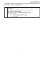
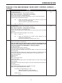
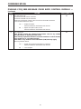
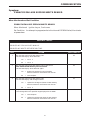
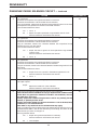
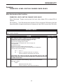
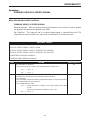
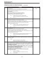
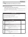
TABLE OF CONTENTS
1.0
INTRODUCTION . . . . . . . . . . . . . . . . . . . . . . . . . . . . . . . . . . . . . . . . . . . . . . . . . . . . . . . . .1
1.1
1.2
SYSTEM COVERAGE . . . . . . . . . . . . . . . . . . . . . . . . . . . . . . . . . . . . . . . . . . . . . . .1
SIX-STEP TROUBLESHOOTING PROCEDURE . . . . . . . . . . . . . . . . . . . . . . . . . .1
2.0
IDENTIFICATION OF SYSTEM . . . . . . . . . . . . . . . . . . . . . . . . . . . . . . . . . . . . . . . . . . . . .1
3.0
SYSTEM DESCRIPTION AND FUNCTIONAL OPERATION . . . . . . . . . . . . . . . . . . . . . .1
3.1
3.2
3.3
3.4
3.5
4.0
GENERAL DESCRIPTION . . . . . . . . . . . . . . . . . . . . . . . . . . . . . . . . . . . . . . . . . . . .1
FUNCTION OPERATION . . . . . . . . . . . . . . . . . . . . . . . . . . . . . . . . . . . . . . . . . . . . .1
3.2.1 FUEL CONTROL . . . . . . . . . . . . . . . . . . . . . . . . . . . . . . . . . . . . . . . . . . . . .1
3.2.2 ON-BOARD DIAGNOSTICS . . . . . . . . . . . . . . . . . . . . . . . . . . . . . . . . . . . .1
3.2.3 OTHER CONTROLS . . . . . . . . . . . . . . . . . . . . . . . . . . . . . . . . . . . . . . . . . .4
3.2.4 PCM OPERATING MODES . . . . . . . . . . . . . . . . . . . . . . . . . . . . . . . . . . . .4
3.2.5 NON-MONITORED CIRCUITS . . . . . . . . . . . . . . . . . . . . . . . . . . . . . . . . . .5
3.2.6 SKIS OVERVIEW . . . . . . . . . . . . . . . . . . . . . . . . . . . . . . . . . . . . . . . . . . . .5
3.2.7 SKIM ON-BOARD DIAGNOSTICS . . . . . . . . . . . . . . . . . . . . . . . . . . . . . . .5
3.2.8 SKIS OPERATION. . . . . . . . . . . . . . . . . . . . . . . . . . . . . . . . . . . . . . . . . . . .6
3.2.9 PROGRAMMING THE POWERTRAIN CONTROL MODULE. . . . . . . . . .6
3.2.10 PROGRAMMING THE SENTRY KEY IMMOBILIZER MODULE . . . . . . .7
3.2.11 PROGRAMMING THE IGNITION KEYS TO THE SENTRY KEY
IMMOBILIZER MODULE. . . . . . . . . . . . . . . . . . . . . . . . . . . . . . . . . . . . . . .7
DIAGNOSTIC TROUBLE CODES . . . . . . . . . . . . . . . . . . . . . . . . . . . . . . . . . . . . . .7
3.3.1 HARD CODE . . . . . . . . . . . . . . . . . . . . . . . . . . . . . . . . . . . . . . . . . . . . . . . .7
3.3.2 INTERMITTENT CODE. . . . . . . . . . . . . . . . . . . . . . . . . . . . . . . . . . . . . . . .8
3.3.3 RESET COUNTER . . . . . . . . . . . . . . . . . . . . . . . . . . . . . . . . . . . . . . . . . . .8
3.3.4 HANDLING NO TROUBLE CODE PROBLEMS . . . . . . . . . . . . . . . . . . . .8
USING THE DRBIIIT . . . . . . . . . . . . . . . . . . . . . . . . . . . . . . . . . . . . . . . . . . . . . . . .11
DRB ERROR MESSAGES AND BLANK SCREEN . . . . . . . . . . . . . . . . . . . . . . . .11
3.5.1 DRB IIIT DOES NOT POWER UP . . . . . . . . . . . . . . . . . . . . . . . . . . . . . .11
3.5.2 DISPLAY IS NOT VISIBLE . . . . . . . . . . . . . . . . . . . . . . . . . . . . . . . . . . . .11
DISCLAIMERS, SAFETY, WARNINGS . . . . . . . . . . . . . . . . . . . . . . . . . . . . . . . . . . . . . .11
4.1
4.2
4.3
DISCLAIMERS. . . . . . . . . . . . . . . . . . . . . . . . . . . . . . . . . . . . . . . . . . . . . . . . . . . . .11
SAFETY . . . . . . . . . . . . . . . . . . . . . . . . . . . . . . . . . . . . . . . . . . . . . . . . . . . . . . . . . .11
4.2.1 TECHNICIAN SAFETY INFORMATION . . . . . . . . . . . . . . . . . . . . . . . . . .11
4.2.2 VEHICLE PREPARATION FOR TESTING. . . . . . . . . . . . . . . . . . . . . . . .12
4.2.3 SERVICING SUB-ASSEMBLIES . . . . . . . . . . . . . . . . . . . . . . . . . . . . . . .12
4.2.4 DRBIIIT SAFETY INFORMATION. . . . . . . . . . . . . . . . . . . . . . . . . . . . . . .12
WARNINGS AND CAUTIONS . . . . . . . . . . . . . . . . . . . . . . . . . . . . . . . . . . . . . . . .12
4.3.1 ROAD TEST WARNINGS . . . . . . . . . . . . . . . . . . . . . . . . . . . . . . . . . . . . .12
4.3.2 VEHICLE DAMAGE CAUTIONS . . . . . . . . . . . . . . . . . . . . . . . . . . . . . . .12
4.3.3 ELECTRONIC PINION FACTOR WARNING . . . . . . . . . . . . . . . . . . . . . .13
5.0
REQUIRED TOOLS AND EQUIPMENT . . . . . . . . . . . . . . . . . . . . . . . . . . . . . . . . . . . . .13
6.0
GLOSSARY OF TERMS. . . . . . . . . . . . . . . . . . . . . . . . . . . . . . . . . . . . . . . . . . . . . . . . . .13
i
TABLE OF CONTENTS - Continued
7.0
DIAGNOSTIC INFORMATION AND PROCEDURES . . . . . . . . . . . . . . . . . . . . . . . . . . .15
CHARGING
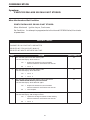
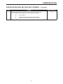
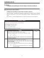
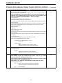
P0622-GENERATOR FIELD NOT SWITCHING PROPERLY . . . . . . . . . . . . . . . . . . . . .16
P1478-BATTERY TEMP SENSOR VOLTS OUT OF LIMIT . . . . . . . . . . . . . . . . . . . . . .18
P1492-AMBIENT/BATT TEMP SEN VOLTS TOO HIGH. . . . . . . . . . . . . . . . . . . . . . . . .19
P1493-AMBIENT/BATT TEMP SEN VOLTS TOO LOW . . . . . . . . . . . . . . . . . . . . . . . . .19
P1594-CHARGING SYSTEM VOLTAGE TOO HIGH . . . . . . . . . . . . . . . . . . . . . . . . . . .22
P1682-CHARGING SYSTEM VOLTAGE TOO LOW . . . . . . . . . . . . . . . . . . . . . . . . . . . .24
*CHECKING CHARGING SYSTEM OPERATION WITH NO DTC’S PRESENT . . . . . .27
*CHECKING THE AMBIENT/BATTERY TEMPERATURE SENSOR . . . . . . . . . . . . . . .30
COMMUNICATION
P0600-PCM FAILURE SPI COMMUNICATIONS. . . . . . . . . . . . . . . . . . . . . . . . . . . . . . .31
P0601-PCM INTERNAL CONTROLLER FAILURE . . . . . . . . . . . . . . . . . . . . . . . . . . . . .31
P1685-INVALID SKIM KEY. . . . . . . . . . . . . . . . . . . . . . . . . . . . . . . . . . . . . . . . . . . . . . . .32
P1686-NO SKIM BUS MESSAGE RECEIVED . . . . . . . . . . . . . . . . . . . . . . . . . . . . . . . .34
P1687-NO CLUSTER BUS MESSAGE . . . . . . . . . . . . . . . . . . . . . . . . . . . . . . . . . . . . . .36
P1695-NO CCD/J1850 MESSAGE FROM BODY CONTROL MODULE . . . . . . . . . . . .38
P1696-PCM FAILURE EEPROM WRITE DENIED . . . . . . . . . . . . . . . . . . . . . . . . . . . . .41
P1697-PCM FAILURE SRI MILE NOT STORED. . . . . . . . . . . . . . . . . . . . . . . . . . . . . . .42
P1698-NO BUS MESSAGE FROM TRANS CONTROL MODULE . . . . . . . . . . . . . . . .44
*BUS +/- SIGNAL OPEN FROM SKIM. . . . . . . . . . . . . . . . . . . . . . . . . . . . . . . . . . . . . . .47
*NO RESPONSE FROM PCM (PCI BUS) . . . . . . . . . . . . . . . . . . . . . . . . . . . . . . . . . . . .49
*NO RESPONSE FROM PCM (SCI ONLY). . . . . . . . . . . . . . . . . . . . . . . . . . . . . . . . . . .51
*NO RESPONSE FROM TCM . . . . . . . . . . . . . . . . . . . . . . . . . . . . . . . . . . . . . . . . . . . . .53
*PCI BUS COMMUNICATION FAILURE . . . . . . . . . . . . . . . . . . . . . . . . . . . . . . . . . . . . .56
DRIVEABILITY
P0106-BAROMETRIC PRESSURE OUT OF RANGE . . . . . . . . . . . . . . . . . . . . . . . . . .59
P0107-MAP SENSOR VOLTAGE TOO LOW . . . . . . . . . . . . . . . . . . . . . . . . . . . . . . . . .63
P0108-MAP SENSOR VOLTAGE TOO HIGH . . . . . . . . . . . . . . . . . . . . . . . . . . . . . . . . .66
P0112-INTAKE AIR TEMP SENSOR VOLTAGE LOW . . . . . . . . . . . . . . . . . . . . . . . . . .69
P0113-INTAKE AIR TEMP SENSOR VOLTAGE HIGH . . . . . . . . . . . . . . . . . . . . . . . . . .71
P0117-ECT SENSOR VOLTAGE TOO LOW . . . . . . . . . . . . . . . . . . . . . . . . . . . . . . . . . .73
P0118-ECT SENSOR VOLTAGE TOO HIGH . . . . . . . . . . . . . . . . . . . . . . . . . . . . . . . . .75
P0121-TPS VOLTAGE DOES NOT AGREE WITH MAP . . . . . . . . . . . . . . . . . . . . . . . .77
P0122-THROTTLE POSITION SENSOR VOLTAGE LOW . . . . . . . . . . . . . . . . . . . . . . .81
P0123-THROTTLE POSITION SENSOR VOLTAGE HIGH . . . . . . . . . . . . . . . . . . . . . .84
P0125-CLOSED LOOP TEMP NOT REACHED . . . . . . . . . . . . . . . . . . . . . . . . . . . . . . .87
P1281-ENGINE IS COLD TOO LONG. . . . . . . . . . . . . . . . . . . . . . . . . . . . . . . . . . . . . . .87
P0131-1/1 O2 SENSOR SHORTED TO GROUND . . . . . . . . . . . . . . . . . . . . . . . . . . . . .89
P0137-1/2 O2 SENSOR SHORTED TO GROUND . . . . . . . . . . . . . . . . . . . . . . . . . . . . .89
P0151-2/1 O2 SENSOR SHORTED TO GROUND . . . . . . . . . . . . . . . . . . . . . . . . . . . . .89
P0157-2/2 O2 SENSOR SHORTED TO GROUND . . . . . . . . . . . . . . . . . . . . . . . . . . . . .89
P0132-1/1 O2 SENSOR SHORTED TO VOLTAGE . . . . . . . . . . . . . . . . . . . . . . . . . . . .92
P0138-1/2 O2 SENSOR SHORTED TO VOLTAGE . . . . . . . . . . . . . . . . . . . . . . . . . . . .92
P0152-2/1 O2 SENSOR SHORTED TO VOLTAGE . . . . . . . . . . . . . . . . . . . . . . . . . . . .92
P0158-2/2 O2 SENSOR SHORTED TO VOLTAGE . . . . . . . . . . . . . . . . . . . . . . . . . . . .92
P0133-1/1 O2 SENSOR SLOW RESPONSE . . . . . . . . . . . . . . . . . . . . . . . . . . . . . . . . .95
P0134 - 1/1 O2 SENSOR STAYS AT CENTER . . . . . . . . . . . . . . . . . . . . . . . . . . . . . . . .95
P0139-1/2 O2 SENSOR SLOW RESPONSE . . . . . . . . . . . . . . . . . . . . . . . . . . . . . . . . .95
P0140-1/2 O2 SENSOR STAYS AT CENTER . . . . . . . . . . . . . . . . . . . . . . . . . . . . . . . . .95
ii
TABLE OF CONTENTS - Continued
P0153-2/1 O2 SENSOR SLOW RESPONSE . . . . . . . . . . . . . . . . . . . . . . . . . . . . . . . . .95
P0154-2/1 02 SENSOR STAYS AT CENTER . . . . . . . . . . . . . . . . . . . . . . . . . . . . . . . . .95
P0160-2/2 O2 SENSOR STAYS AT CENTER . . . . . . . . . . . . . . . . . . . . . . . . . . . . . . . . .95
P0135-1/1 O2 SENSOR HEATER FAILURE . . . . . . . . . . . . . . . . . . . . . . . . . . . . . . . . . .97
P0141-1/2 O2 SENSOR HEATER FAILURE . . . . . . . . . . . . . . . . . . . . . . . . . . . . . . . . . .97
P0155-2/1 O2 SENSOR HEATER FAILURE . . . . . . . . . . . . . . . . . . . . . . . . . . . . . . . . . .97
P0161-2/2 O2 SENSOR HEATER FAILURE . . . . . . . . . . . . . . . . . . . . . . . . . . . . . . . . . .97
P0171-1/1 FUEL SYSTEM LEAN . . . . . . . . . . . . . . . . . . . . . . . . . . . . . . . . . . . . . . . . . .100
P0174-2/1 FUEL SYSTEM LEAN . . . . . . . . . . . . . . . . . . . . . . . . . . . . . . . . . . . . . . . . . .100
P0172-1/1 FUEL SYSTEM RICH . . . . . . . . . . . . . . . . . . . . . . . . . . . . . . . . . . . . . . . . . .106
P0175-2/1 FUEL SYSTEM RICH . . . . . . . . . . . . . . . . . . . . . . . . . . . . . . . . . . . . . . . . . .106
P0201-INJECTOR #1 CONTROL CIRCUIT . . . . . . . . . . . . . . . . . . . . . . . . . . . . . . . . . .112
P0202-INJECTOR #2 CONTROL CIRCUIT . . . . . . . . . . . . . . . . . . . . . . . . . . . . . . . . . .115
P0203-INJECTOR #3 CONTROL CIRCUIT . . . . . . . . . . . . . . . . . . . . . . . . . . . . . . . . . .118
P0204-INJECTOR #4 CONTROL CIRCUIT . . . . . . . . . . . . . . . . . . . . . . . . . . . . . . . . . .121
P0205-INJECTOR #5 CONTROL CIRCUIT . . . . . . . . . . . . . . . . . . . . . . . . . . . . . . . . . .124
P0206-INJECTOR #6 CONTROL CIRCUIT . . . . . . . . . . . . . . . . . . . . . . . . . . . . . . . . . .127
P0300-MULTIPLE CYLINDER MIS-FIRE. . . . . . . . . . . . . . . . . . . . . . . . . . . . . . . . . . . .130
P0301-CYLINDER #1 MISFIRE . . . . . . . . . . . . . . . . . . . . . . . . . . . . . . . . . . . . . . . . . . .130
P0302-CYLINDER #2 MISFIRE . . . . . . . . . . . . . . . . . . . . . . . . . . . . . . . . . . . . . . . . . . .130
P0303-CYLINDER #3 MISFIRE . . . . . . . . . . . . . . . . . . . . . . . . . . . . . . . . . . . . . . . . . . .130
P0304-CYLINDER #4 MISFIRE . . . . . . . . . . . . . . . . . . . . . . . . . . . . . . . . . . . . . . . . . . .130
P0305-CYLINDER #5 MISFIRE . . . . . . . . . . . . . . . . . . . . . . . . . . . . . . . . . . . . . . . . . . .130
P0306-CYLINDER #6 MISFIRE . . . . . . . . . . . . . . . . . . . . . . . . . . . . . . . . . . . . . . . . . . .130
P0320-NO CRANK REFERENCE SIGNAL AT PCM . . . . . . . . . . . . . . . . . . . . . . . . . . .134
P0325-KNOCK SENSOR #1 CIRCUIT . . . . . . . . . . . . . . . . . . . . . . . . . . . . . . . . . . . . .141
P0340-NO CAM SIGNAL AT PCM . . . . . . . . . . . . . . . . . . . . . . . . . . . . . . . . . . . . . . . . .144
P0351-IGNITION COIL #1 PRIMARY CIRCUIT . . . . . . . . . . . . . . . . . . . . . . . . . . . . . .150
P0352-IGNITION COIL #2 PRIMARY CIRCUIT . . . . . . . . . . . . . . . . . . . . . . . . . . . . . .153
P0353-IGNITION COIL #3 PRIMARY CIRCUIT . . . . . . . . . . . . . . . . . . . . . . . . . . . . . .156
P0354-IGNITION COIL #4 PRIMARY CIRCUIT . . . . . . . . . . . . . . . . . . . . . . . . . . . . . .159
P0355-IGNITION COIL #5 PRIMARY CIRCUIT . . . . . . . . . . . . . . . . . . . . . . . . . . . . . .162
P0356-IGNITION COIL #6 PRIMARY CIRCUIT . . . . . . . . . . . . . . . . . . . . . . . . . . . . . .165
P0401 - EGR SYSTEM FAILURE . . . . . . . . . . . . . . . . . . . . . . . . . . . . . . . . . . . . . . . . .168
P0403 - EGR SOLENOID CIRCUIT . . . . . . . . . . . . . . . . . . . . . . . . . . . . . . . . . . . . . . . .172
P0404 - EGR POSITION SENSOR RATIONALITY. . . . . . . . . . . . . . . . . . . . . . . . . . . .175
P0405 - EGR POSITION SENSOR VOLTAGE TOO LOW . . . . . . . . . . . . . . . . . . . . . .177
P0406 - EGR POSITION SENSOR VOLTS TOO HIGH . . . . . . . . . . . . . . . . . . . . . . . .179
P0420-1/1 CATALYTIC CONVERTER EFFICIENCY. . . . . . . . . . . . . . . . . . . . . . . . . . .182
P0432-2/1 CATALYTIC CONVERTER EFFICIENCY. . . . . . . . . . . . . . . . . . . . . . . . . . .184
P0441-EVAP PURGE FLOW MONITOR . . . . . . . . . . . . . . . . . . . . . . . . . . . . . . . . . . . .186
P0442-EVAP LEAK MONITOR MEDIUM (.040) LEAK DETECTED. . . . . . . . . . . . . . .188
P0455-EVAP LEAK MONITOR LARGE LEAK DETECTED . . . . . . . . . . . . . . . . . . . . .188
P0443-EVAP PURGE SOLENOID CIRCUIT . . . . . . . . . . . . . . . . . . . . . . . . . . . . . . . . .191
P0460-FUEL LEVEL UNIT NO CHANGE OVER MILES. . . . . . . . . . . . . . . . . . . . . . . .193
P0462-FUEL LEVEL SENDING UNIT VOLTS TOO LOW. . . . . . . . . . . . . . . . . . . . . . .194
P0463-FUEL LEVEL SENDING UNIT VOLTS TOO HIGH . . . . . . . . . . . . . . . . . . . . . .194
P0500-NO VEHICLE SPEED SIGNAL. . . . . . . . . . . . . . . . . . . . . . . . . . . . . . . . . . . . . .195
P0505-IDLE AIR CONTROL MOTOR CIRCUITS . . . . . . . . . . . . . . . . . . . . . . . . . . . . .197
P0551-POWER STEERING SWITCH FAILURE . . . . . . . . . . . . . . . . . . . . . . . . . . . . . .203
P0700-EATX CONTROLLER DTC PRESENT. . . . . . . . . . . . . . . . . . . . . . . . . . . . . . . .205
P0703-BRAKE SWITCH SENSE CIRCUIT . . . . . . . . . . . . . . . . . . . . . . . . . . . . . . . . . .206
*BRAKE SWITCH SENSE STATUS DOES NOT CHANGE ON DRB . . . . . . . . . . . . .206
iii
TABLE OF CONTENTS - Continued
P1195-1/1 O2 SENSOR SLOW DURING CATALYST MONITOR . . . . . . . . . . . . . . . .208
P1196-2/1 O2 SENSOR SLOW DURING CATALYST MONITOR . . . . . . . . . . . . . . . .208
P1282-FUEL PUMP RELAY CONTROL CIRCUIT. . . . . . . . . . . . . . . . . . . . . . . . . . . . .210
P1288-SHORT RUNNER SOLENOID CIRCUIT . . . . . . . . . . . . . . . . . . . . . . . . . . . . . .212
P1289-MANIFOLD TUNE VALVE CONTROL CIRCUIT . . . . . . . . . . . . . . . . . . . . . . . .214
P1294-TARGET IDLE NOT REACHED . . . . . . . . . . . . . . . . . . . . . . . . . . . . . . . . . . . . .216
P1297-NO CHANGE IN MAP FROM START TO RUN . . . . . . . . . . . . . . . . . . . . . . . . .218
P1299-VACUUM LEAK FOUND (IAC FULLY SEATED) . . . . . . . . . . . . . . . . . . . . . . . .223
P1388-AUTO SHUTDOWN RELAY CONTROL CIRCUIT. . . . . . . . . . . . . . . . . . . . . . .225
P1389-NO ASD RELAY OUTPUT VOLTAGE AT PCM . . . . . . . . . . . . . . . . . . . . . . . . .227
P1391-INTERMITTENT LOSS OF CMP OR CKP. . . . . . . . . . . . . . . . . . . . . . . . . . . . .230
P1398-MIS-FIRE ADAPTIVE NUMERATOR AT LIMIT . . . . . . . . . . . . . . . . . . . . . . . . .234
P1486-EVAP LEAK MONITOR PINCHED HOSE FOUND . . . . . . . . . . . . . . . . . . . . . .236
P1489-HIGH SPEED FAN CONTROL RELAY CIRCUIT . . . . . . . . . . . . . . . . . . . . . . .239
P1490-LOW SPEED FAN CONTROL RELAY CIRCUIT . . . . . . . . . . . . . . . . . . . . . . . .241
P1494-LEAK DETECT PUMP SW OR MECHANICAL FAULT . . . . . . . . . . . . . . . . . . .243
P1495-LEAK DETECTION PUMP SOLENOID CIRCUIT . . . . . . . . . . . . . . . . . . . . . . .245
P1496-5 VOLT SUPPLY, OUTPUT TOO LOW . . . . . . . . . . . . . . . . . . . . . . . . . . . . . . .247
*CHECKING BRAKE SWITCH OPERATION WITH NO DTC’S . . . . . . . . . . . . . . . . . .250
*CHECKING ENGINE MECHANICAL SYSTEMS . . . . . . . . . . . . . . . . . . . . . . . . . . . . .251
*CHECKING ENGINE VACUUM . . . . . . . . . . . . . . . . . . . . . . . . . . . . . . . . . . . . . . . . . .252
*CHECKING EVAPORATIVE EMISSION SYSTEM. . . . . . . . . . . . . . . . . . . . . . . . . . . .253
*CHECKING FUEL DELIVERY. . . . . . . . . . . . . . . . . . . . . . . . . . . . . . . . . . . . . . . . . . . .255
*CHECKING IAC MOTOR OPERATION WITH NO DTC’S. . . . . . . . . . . . . . . . . . . . . .258
*CHECKING MAP SENSOR OPERATION WITH NO DTC’S . . . . . . . . . . . . . . . . . . . .260
*CHECKING MINIMUM IDLE AIRFLOW . . . . . . . . . . . . . . . . . . . . . . . . . . . . . . . . . . . .261
*CHECKING RADIATOR FAN OPERATION WITH NO DTC’S. . . . . . . . . . . . . . . . . . .263
*CHECKING THE ENGINE COOLANT TEMPERATURE SENSOR. . . . . . . . . . . . . . .265
*CHECKING THE INTAKE AIR TEMPERATURE SENSOR . . . . . . . . . . . . . . . . . . . . .266
*CHECKING THE PCM POWER AND GROUNDS . . . . . . . . . . . . . . . . . . . . . . . . . . . .267
*CHECKING THROTTLE POSITION SENSOR OPERATION WITH NO DTC’S. . . . .268
HEATING & A/C
P0645-A/C CLUTCH RELAY CKT . . . . . . . . . . . . . . . . . . . . . . . . . . . . . . . . . . . . . . . . .270
P1598-A/C PRESSURE SENSOR VOLTS TOO HIGH . . . . . . . . . . . . . . . . . . . . . . . . .272
P1599-A/C PRESSURE SENSOR VOLTS TOO LOW . . . . . . . . . . . . . . . . . . . . . . . . .274
*CHECKING A/C SYSTEM OPERATION WITH NO DTC’S . . . . . . . . . . . . . . . . . . . . .276
SPEED CONTROL
P1595-SPEED CONTROL SOLENOID CIRCUITS . . . . . . . . . . . . . . . . . . . . . . . . . . . .278
P1683-SPD CTRL PWR RELAY; OR S/C 12V DRIVER CKT . . . . . . . . . . . . . . . . . . .278
P1597-SPEED CONTROL SWITCH ALWAYS LOW . . . . . . . . . . . . . . . . . . . . . . . . . . .285
*CHECKING SPEED CONTROL OPERATION WITH NO DTC’S PRESENT . . . . . . .288
STARTING
*ENGINE CRANKS DOES NOT START . . . . . . . . . . . . . . . . . . . . . . . . . . . . . . . . . . . .297
*NO CRANK CONDITION. . . . . . . . . . . . . . . . . . . . . . . . . . . . . . . . . . . . . . . . . . . . . . . .304
*NO RESPONSE FROM PCM WITH A NO START CONDITION . . . . . . . . . . . . . . . .307
*START AND STALL CONDITION . . . . . . . . . . . . . . . . . . . . . . . . . . . . . . . . . . . . . . . . .311
TRANSMISSION
P1899-P/N SWITCH STUCK IN PARK OR IN GEAR . . . . . . . . . . . . . . . . . . . . . . . . . .316
*CHECKING PARK/NETURAL SWITCH OPERATION . . . . . . . . . . . . . . . . . . . . . . . . .318
iv
TABLE OF CONTENTS - Continued
VEHICLE THEFT/SECURITY
ANTENNA FAILURE . . . . . . . . . . . . . . . . . . . . . . . . . . . . . . . . . . . . . . . . . . . . . . . . . . . .320
COP FAILURE . . . . . . . . . . . . . . . . . . . . . . . . . . . . . . . . . . . . . . . . . . . . . . . . . . . . . . . . .320
EEPROM FAILURE . . . . . . . . . . . . . . . . . . . . . . . . . . . . . . . . . . . . . . . . . . . . . . . . . . . . .320
INTERNAL FAULTS. . . . . . . . . . . . . . . . . . . . . . . . . . . . . . . . . . . . . . . . . . . . . . . . . . . . .320
RAM FAILURE. . . . . . . . . . . . . . . . . . . . . . . . . . . . . . . . . . . . . . . . . . . . . . . . . . . . . . . . .320
SERIAL LINK INTERNAL . . . . . . . . . . . . . . . . . . . . . . . . . . . . . . . . . . . . . . . . . . . . . . . .320
STACK OVERFLOW FAILURE. . . . . . . . . . . . . . . . . . . . . . . . . . . . . . . . . . . . . . . . . . . .320
PCM STATUS FAILURE . . . . . . . . . . . . . . . . . . . . . . . . . . . . . . . . . . . . . . . . . . . . . . . . .321
ROLLING CODE FAILURE . . . . . . . . . . . . . . . . . . . . . . . . . . . . . . . . . . . . . . . . . . . . . . .321
SERIAL LINK EXTERNAL FAULT . . . . . . . . . . . . . . . . . . . . . . . . . . . . . . . . . . . . . . . . .321
TRANSPONDER (CYCLIC REDUNDANCY CHECK) CRC FAILURE . . . . . . . . . . . . .323
TRANSPONDER COMMUNICATION FAILURE . . . . . . . . . . . . . . . . . . . . . . . . . . . . . .323
TRANSPONDER ID MISMATCH . . . . . . . . . . . . . . . . . . . . . . . . . . . . . . . . . . . . . . . . . .323
TRANSPONDER RESPONSE MISMATCH . . . . . . . . . . . . . . . . . . . . . . . . . . . . . . . . . .323
VIN MISMATCH. . . . . . . . . . . . . . . . . . . . . . . . . . . . . . . . . . . . . . . . . . . . . . . . . . . . . . . .325
VERIFICATION TESTS
VERIFICATION TESTS . . . . . . . . . . . . . . . . . . . . . . . . . . . . . . . . . . . . . . . . . . . . . . . . . .327
8.0
SYSTEM COMPONENT LOCATIONS. . . . . . . . . . . . . . . . . . . . . . . . . . . . . . . . . . . . . .335
8.1
8.2
8.3
8.4
8.5
8.7
9.0
Powertrain, Body and Trans Control Modules . . . . . . . . . . . . . . . . . . . . . . . . . . .335
CONTROLS & SOLENOIDS. . . . . . . . . . . . . . . . . . . . . . . . . . . . . . . . . . . . . . . . .335
DATA LINK CONNECTOR . . . . . . . . . . . . . . . . . . . . . . . . . . . . . . . . . . . . . . . . . .337
Sensors . . . . . . . . . . . . . . . . . . . . . . . . . . . . . . . . . . . . . . . . . . . . . . . . . . . . . . . . .338
Fuel System. . . . . . . . . . . . . . . . . . . . . . . . . . . . . . . . . . . . . . . . . . . . . . . . . . . . . .341
Switches. . . . . . . . . . . . . . . . . . . . . . . . . . . . . . . . . . . . . . . . . . . . . . . . . . . . . . . . .341
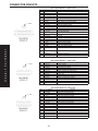
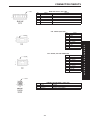
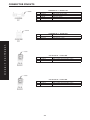
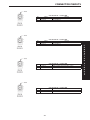
CONNECTOR PINOUTS . . . . . . . . . . . . . . . . . . . . . . . . . . . . . . . . . . . . . . . . . . . . . . . .343
A/C COMPRESSOR CLUTCH - BLACK 2 WAY . . . . . . . . . . . . . . . . . . . . . . . . . . . . . .343
A/C PRESSURE TRANSDUCER - GRAY 4 WAY . . . . . . . . . . . . . . . . . . . . . . . . . . . . .343
AMBIENT TEMPERATURE SENSOR - 2 WAY . . . . . . . . . . . . . . . . . . . . . . . . . . . . . . .343
BODY CONTROL MODULE C1 - GRAY 14 WAY . . . . . . . . . . . . . . . . . . . . . . . . . . . . .343
BODY CONTROL MODULE C2 - BLACK 24 WAY . . . . . . . . . . . . . . . . . . . . . . . . . . . .344
BODY CONTROL MODULE C3 - WHITE 12 WAY . . . . . . . . . . . . . . . . . . . . . . . . . . . .344
BODY CONTROL MODULE C4 - BLUE 16 WAY . . . . . . . . . . . . . . . . . . . . . . . . . . . . .344
BRAKE LAMP SWITCH - GRAY 6 WAY . . . . . . . . . . . . . . . . . . . . . . . . . . . . . . . . . . . .345
C308 - NATURAL (BODY SIDE) . . . . . . . . . . . . . . . . . . . . . . . . . . . . . . . . . . . . . . . . . .345
C308 - NATURAL (FUEL TANK JUMPER SIDE). . . . . . . . . . . . . . . . . . . . . . . . . . . . . .345
CAMSHAFT POSITION SENSOR - BLACK 3 WAY . . . . . . . . . . . . . . . . . . . . . . . . . . .345
CLOCKSPRING NO. 1 - NATURAL 5 WAY . . . . . . . . . . . . . . . . . . . . . . . . . . . . . . . . . .346
CLOCKSPRING NO. 2 - YELLOW 2 WAY . . . . . . . . . . . . . . . . . . . . . . . . . . . . . . . . . .346
COIL ON PLUG NO. 1 - BLACK 2 WAY . . . . . . . . . . . . . . . . . . . . . . . . . . . . . . . . . . . .346
COIL ON PLUG NO. 2 - BLACK 2 WAY . . . . . . . . . . . . . . . . . . . . . . . . . . . . . . . . . . . .346
COIL ON PLUG NO. 3 - BLACK 2 WAY . . . . . . . . . . . . . . . . . . . . . . . . . . . . . . . . . . . .347
COIL ON PLUG NO. 4 - BLACK 2 WAY . . . . . . . . . . . . . . . . . . . . . . . . . . . . . . . . . . . .347
COIL ON PLUG NO. 5 - BLACK 2 WAY . . . . . . . . . . . . . . . . . . . . . . . . . . . . . . . . . . . .347
COIL ON PLUG NO. 6 - BLACK 2 WAY . . . . . . . . . . . . . . . . . . . . . . . . . . . . . . . . . . . .347
CRANKSHAFT POSITION SENSOR (2.7L) - BLACK 3 WAY . . . . . . . . . . . . . . . . . . .348
CRANKSHAFT POSITION SENSOR (3.2L/3.5L) - 3 WAY . . . . . . . . . . . . . . . . . . . . . .348
DATA LINK CONNECTOR - BLACK 16 WAY . . . . . . . . . . . . . . . . . . . . . . . . . . . . . . . .348
v
TABLE OF CONTENTS - Continued
EGR SOLENOID - BLACK 6 WAY . . . . . . . . . . . . . . . . . . . . . . . . . . . . . . . . . . . . . . . . .349
ENGINE OIL PRESSURE SWITCH - GREEN 2 WAY . . . . . . . . . . . . . . . . . . . . . . . . .349
EVAP/PURGE SOLENOID - BLACK 2 WAY . . . . . . . . . . . . . . . . . . . . . . . . . . . . . . . . .349
FUEL INJECTOR NO. 1 - BLACK 2 WAY . . . . . . . . . . . . . . . . . . . . . . . . . . . . . . . . . . .349
FUEL INJECTOR NO. 2 - BLACK 2 WAY . . . . . . . . . . . . . . . . . . . . . . . . . . . . . . . . . . .350
FUEL INJECTOR NO. 3 - BLACK 2 WAY . . . . . . . . . . . . . . . . . . . . . . . . . . . . . . . . . . .350
FUEL INJECTOR NO. 4 - BLACK 2 WAY . . . . . . . . . . . . . . . . . . . . . . . . . . . . . . . . . . .350
FUEL INJECTOR NO. 5 - BLACK 2 WAY . . . . . . . . . . . . . . . . . . . . . . . . . . . . . . . . . . .350
FUEL INJECTOR NO. 6 - BLACK 2 WAY . . . . . . . . . . . . . . . . . . . . . . . . . . . . . . . . . . .351
FUEL PUMP MODULE - GRAY 4 WAY . . . . . . . . . . . . . . . . . . . . . . . . . . . . . . . . . . . . .351
GENERATOR (2.7L) - 2 WAY. . . . . . . . . . . . . . . . . . . . . . . . . . . . . . . . . . . . . . . . . . . . .351
GENERATOR (3.2L/3.5L) - BLACK 2 WAY . . . . . . . . . . . . . . . . . . . . . . . . . . . . . . . . . .351
IDLE AIR CONTROL MOTOR - BLACK 4 WAY . . . . . . . . . . . . . . . . . . . . . . . . . . . . . .352
INTAKE AIR TEMPERATURE SENSOR (2.7L) - GRAY 2 WAY . . . . . . . . . . . . . . . . . .352
INTAKE AIR TEMPERATURE/MANIFOLD ABSOLUTE PRESSURE SENSOR
(3.2L/3.5L) . . . . . . . . . . . . . . . . . . . . . . . . . . . . . . . . . . . . . . . . . . . . . . . . . . . . . . . . . . . .352
FUSES . . . . . . . . . . . . . . . . . . . . . . . . . . . . . . . . . . . . . . . . . . . . . . . . . . . . . . . . . . . . . . .354
CIRCUIT BREAKERS . . . . . . . . . . . . . . . . . . . . . . . . . . . . . . . . . . . . . . . . . . . . . . . . . . .354
DAYTIME RUNNING LAMP MODULE . . . . . . . . . . . . . . . . . . . . . . . . . . . . . . . . . . . . . .354
DOOR LOCK RELAY . . . . . . . . . . . . . . . . . . . . . . . . . . . . . . . . . . . . . . . . . . . . . . . . . . .354
DOOR UNLOCK RELAY . . . . . . . . . . . . . . . . . . . . . . . . . . . . . . . . . . . . . . . . . . . . . . . . .354
DRIVER DOOR UNLOCK RELAY . . . . . . . . . . . . . . . . . . . . . . . . . . . . . . . . . . . . . . . . .355
FOG LAMP RELAY . . . . . . . . . . . . . . . . . . . . . . . . . . . . . . . . . . . . . . . . . . . . . . . . . . . . .355
HIGH BEAM HEADLAMP RELAY . . . . . . . . . . . . . . . . . . . . . . . . . . . . . . . . . . . . . . . . .355
HORN RELAY . . . . . . . . . . . . . . . . . . . . . . . . . . . . . . . . . . . . . . . . . . . . . . . . . . . . . . . . .355
LOW BEAM HEADLAMP RELAY . . . . . . . . . . . . . . . . . . . . . . . . . . . . . . . . . . . . . . . . . .355
PARK LAMP RELAY . . . . . . . . . . . . . . . . . . . . . . . . . . . . . . . . . . . . . . . . . . . . . . . . . . . .355
SPARE RELAY . . . . . . . . . . . . . . . . . . . . . . . . . . . . . . . . . . . . . . . . . . . . . . . . . . . . . . . .355
JUNCTION BLOCK BODY CONTROL MODULE - JB . . . . . . . . . . . . . . . . . . . . . . . . .357
KNOCK SENSOR (2.7L) - GRAY 2 WAY. . . . . . . . . . . . . . . . . . . . . . . . . . . . . . . . . . . .357
KNOCK SENSOR (3.2L/3.5L) - BLACK 2 WAY. . . . . . . . . . . . . . . . . . . . . . . . . . . . . . .357
LEAK DETECTION PUMP - BLACK 4 WAY . . . . . . . . . . . . . . . . . . . . . . . . . . . . . . . . .357
MANIFOLD ABSOLUTE PRESSURE SENSOR (2.7L) - BLACK 3 WAY. . . . . . . . . . .358
MANIFOLD TUNING VALVE - BLACK 2 WAY. . . . . . . . . . . . . . . . . . . . . . . . . . . . . . . .358
OUTPUT SPEED SENSOR - DK BLUE 2 WAY . . . . . . . . . . . . . . . . . . . . . . . . . . . . . .358
OXYGEN SENSOR 1/1 RIGHT BANK UP - BLACK 4 WAY. . . . . . . . . . . . . . . . . . . . .358
OXYGEN SENSOR 1/2 RIGHT BANK DOWN - BLACK 4 WAY . . . . . . . . . . . . . . . . .359
OXYGEN SENSOR 2/1 LEFT BANK UP - BLACK 4 WAY . . . . . . . . . . . . . . . . . . . . . .359
OXYGEN SENSOR 2/2 LEFT BANK DOWN - BLACK 4 WAY . . . . . . . . . . . . . . . . . .359
FUSES . . . . . . . . . . . . . . . . . . . . . . . . . . . . . . . . . . . . . . . . . . . . . . . . . . . . . . . . . . . . . . .361
A/C COMPRESSOR CLUTCH RELAY. . . . . . . . . . . . . . . . . . . . . . . . . . . . . . . . . . . . . .361
AUTOMATIC SHUT DOWN RELAY . . . . . . . . . . . . . . . . . . . . . . . . . . . . . . . . . . . . . . . .361
ENGINE STARTER MOTOR RELAY . . . . . . . . . . . . . . . . . . . . . . . . . . . . . . . . . . . . . . .361
FUEL PUMP RELAY . . . . . . . . . . . . . . . . . . . . . . . . . . . . . . . . . . . . . . . . . . . . . . . . . . . .361
HEADLAMP WASHER RELAY (BUILT-UP-EXPORT) . . . . . . . . . . . . . . . . . . . . . . . . . .361
HIGH SPEED RADIATOR FAN RELAY . . . . . . . . . . . . . . . . . . . . . . . . . . . . . . . . . . . . .362
LOW SPEED RADIATOR FAN RELAY . . . . . . . . . . . . . . . . . . . . . . . . . . . . . . . . . . . . .362
REAR FOG LAMP RELAY (BUILT-UP-EXPORT) . . . . . . . . . . . . . . . . . . . . . . . . . . . . .362
TRANSMISSION CONTROL RELAY . . . . . . . . . . . . . . . . . . . . . . . . . . . . . . . . . . . . . . .362
WIPER HIGH/LOW RELAY. . . . . . . . . . . . . . . . . . . . . . . . . . . . . . . . . . . . . . . . . . . . . . .362
WIPER ON/OFF RELAY . . . . . . . . . . . . . . . . . . . . . . . . . . . . . . . . . . . . . . . . . . . . . . . . .362
POWER STEERING PRESSURE SWITCH - GRAY 2 WAY . . . . . . . . . . . . . . . . . . . .363
POWERTRAIN CONTROL MODULE C1 - 40 WAY . . . . . . . . . . . . . . . . . . . . . . . . . . .363
vi
TABLE OF CONTENTS - Continued
POWERTRAIN CONTROL MODULE C2 - GRAY 40 WAY. . . . . . . . . . . . . . . . . . . . . .364
RADIATOR FAN MOTOR ASSEMBLY - 4 WAY . . . . . . . . . . . . . . . . . . . . . . . . . . . . . .364
SENTRY KEY IMMOBILIZER MODULE - BLACK 6 WAY . . . . . . . . . . . . . . . . . . . . . .365
SHORT RUNNER VALVE SOLENOID (3.2L/3.5L) - DK BLUE 2 WAY . . . . . . . . . . . .365
THROTTLE POSITION SENSOR (2.7L) - BLACK 3 WAY . . . . . . . . . . . . . . . . . . . . . .365
THROTTLE POSITION SENSOR (3.2L/3.5L) - NATURAL 3 WAY. . . . . . . . . . . . . . . .365
TRANSMISSION CONTROL MODULE - BLACK 60 WAY . . . . . . . . . . . . . . . . . . . . . .366
TRANSMISSION RANGE SENSOR - LT. GREEN 10 WAY . . . . . . . . . . . . . . . . . . . . .367
TRANSMISSION SOLENOID/PRESSURE SWITCH ASSEMBLY - BLACK 8 WAY . .367
VEHICLE SPEED CONTROL SERVO - BLACK 4 WAY . . . . . . . . . . . . . . . . . . . . . . . .367
10.0
SCHEMATIC DIAGRAMS. . . . . . . . . . . . . . . . . . . . . . . . . . . . . . . . . . . . . . . . . . . . . . . .369
10.1 ENGINE CONTROLS (2000) . . . . . . . . . . . . . . . . . . . . . . . . . . . . . . . . . . . . . . . .369
vii
NOTES
viii
GENERAL INFORMATION
1.0
•
INTRODUCTION
•
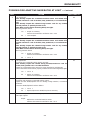
The procedures contained in this manual include
specifications, instructions, and graphics needed to
diagnose the PCM Powertrain System. The diagnostics in this manual are based on the failure
condition or symptom being present at time of
diagnosis.
Please follow the recommendations below when
choosing your diagnostic path.
1. First make sure the DRBIIIt is communicating
with the appropriate modules; ie., if the DRBIIIt
displays a ‘‘No Response’’ condition, you must
diagnose this first before proceeding.
2. Read DTC’s (diagnostic trouble codes) with the
DRBIIIt.
3. If no DTC’s are present, identify the customer
complaint.
4. Once the DTC or customer complaint is identified, locate the matching test in the Table of
Contents and begin to diagnose the symptom.
All component location views are in Section 8.0.
All connector pinouts are in Section 9.0. All system
schematics are in Section 10.0.
An * placed before the symptom description indicates a customer complaint.
When repairs are required, refer to the appropriate service manual for the proper removal and
repair procedure.
Diagnostic procedures change every year. New
diagnostic systems may be added; carryover systems may be enhanced. READ THIS MANUAL
BEFORE TRYING TO DIAGNOSE A VEHICLE
CODE. It is recommended that you review the
entire manual to become familiar with all new and
changed diagnostic procedures.
After using this book, if you have any comments
or recommendations, please fill out the form at the
back of the book and mail it back to us.
1.1
2.0
•
•
•
•
Fuel system
•
•
Ignition system
charging system
speed control system
•
cooling system
•
3.0
3.1
SYSTEM DESCRIPTION AND
FUNCTIONAL OPERATION
GENERAL DESCRIPTION
These Sequential Fuel Injection (SFI) engine systems have the latest in technical advances. The
Euro Stage 3 On-Board Diagnostics incorporated
with the powertrain control module (PCM) are
intended to assist the field technician in repairing
vehicle problems by the quickest means.
3.2
3.2.1
FUNCTION OPERATION
FUEL CONTROL
The PCM controls the air/fuel ratio of the engine
by varying fuel injector on time. Mass air flow is
calculated using the speed density method using
engine speed, manifold absolute pressure, and air
temperature change.
Different fuel calculation strategies are used dependent on the operational state of the engine.
During crank mode, a prime shot fuel pulse is
delivered followed by fuel pulses determined by a
crank time strategy. Cold engine operation is determined via an open loop strategy until the O2
sensors have reached operating temperature. At
this point, the strategy enters a closed loop mode
where fuel requirements are based upon the state of
the O2 sensors, engine speed, MAP, throttle position, air temperature, battery voltage, and coolant
temperature.
SYSTEM COVERAGE
SIX-STEP TROUBLESHOOTING
PROCEDURE
Diagnosis of the powertrain control module
(PCM) is done in six basic steps:
•
IDENTIFICATION OF
SYSTEM
The Powertrain Control Module (PCM) monitors
and controls:
This diagnostic procedures manual covers the
following 2000 Chrysler 300M equipped with a 2.7L
or 3.5L engine.
1.2
repair of isolated problem
verification of proper operation
3.2.2
verification of complaint
verification of any related symptoms
symptom analysis
problem isolation
ON-BOARD DIAGNOSTICS
The PCM has been programmed to monitor many
different circuits of the fuel injection system. This
monitoring is called “on-board diagnosis.”
1
GENERAL INFORMATION
Certain criteria, or “arming conditions,” must be
met for a trouble code to be entered into the PCM
memory. The criteria may be a range of: engine rpm,
engine temperature, and/or input voltage to the
PCM. If a problem is sensed with a monitored
circuit, and all of the criteria or arming conditions
are met, then a trouble code will be stored in the
PCM.
It is possible that a trouble code for a monitored
circuit may not be entered into the PCM memory
even though a malfunction has occurred. This may
happen because one of the trouble code criteria
(arming conditions) have not been met.
The PCM compares input signal voltages from
each input device with specifications (the established high and low limits of the range) that are
programmed into it for that device. If the input
voltage is not within specifications and other trouble code criteria (arming conditions) are met, a
trouble code will be stored in the PCM memory.
The On Board Diagnostics have evolved to a new
Generation of Diagnostics referred to as Euro Stage
3 On-Board Diagnostics
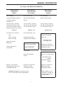
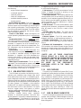
The following table summarizes the various
OBDII monitors operation.
2
GENERAL INFORMATION
Euro Stage III OBD MONITOR INFORMATION
Comprehensive
Components
Monitor
Major Monitors
Non Fuel Control
& Non Misfire
Major Monitors
Fuel Control
& Misfire
Run constantly
Run Once Per Trip
Run Constantly
Includes All Engine Hardware
- Sensors, Switches,
Solenoids, etc.
Monitors Entire Emission
System
Monitors Entire System
One Trip Faults - Turns On
The MIL and Sets DTC After
One Failure (except for most rationality tests which are two trip)
Two Trip Faults - Turns On
The MIL and Sets DTC After
Two Consecutive Failures
Two Trip Faults - Turns On
The MIL and Sets DTC After
Two Consecutive Failures
Priority 3
All Checked For Continuity
Open
Short To Ground
Short To Voltage
Inputs Checked For
Rationality
Outputs Checked For
Functionality
Priority 1 or 3
Priority 2 or 4
Done Stop Testing = Yes
Oxygen Sensor Heater
Oxygen Sensor Response
Fuel Control Monitor
Monitors Fuel Control
System For:
Fuel System Lean
Fuel System Rich
Catalytic Converter
Efficiency Except EWMA
- up to 6 tests per trip
and a one trip fault
Requires 3 Consecutive
Fuel System Good Trips To
Extinguish The MIL
EGR System
Evaporative Emission
System
Requires 3 Consecutive
Global/Alternate Good Trips
to Extinguish the MIL*
Requires 3 Consecutive
Global Good Trips
to Extinguish the MIL*
*40 Warm Up Cycles are required to erase
DTC’s after the MIL has been extinguished.
Misfire Monitor
Monitors For Engine Misfire
at:
1000 RPM Counter
(Type B)
**200 RPM Counter
(Type A)
Requires 3 Consecutive
Misfire Good Trips
To Extinguish the MIL
**Type A misfire is a one
trip failure. The MIL will
illuminate and blink at
the first failure.
3
GENERAL INFORMATION
3.2.3
OTHER CONTROLS
achieve the lowest emission levels while maintaining optimum fuel economy.
The engine start-up (crank), engine warm-up,
and wide open throttle modes are open loop modes.
Under most operating conditions, closed loop modes
occur with the engine at operating temperature.
CHARGING SYSTEM
The charging system is turned on when the
engine is started and ASD relay energized. When
the ASD relay is on, ASD output voltage is supplied
to the ASD sense circuit at the PCM. This voltage is
connected in some cases, through the PCM and
supplied to one of the generator field terminals
(Gen Source +). All others, the Gen field is connected directly to the ASD output voltage. The
amount of current produced by the generator is
controlled by the Electronic Voltage Regulator
(EVR) circuitry, in the PCM. A battery temperature
sensor, located either in the battery tray, using the
ambient sensor, or in the PCM itself, is used to
sense battery temperature. This temperature along
with sensed line voltage, is used by the PCM to vary
the battery charging rate. This is done by cycling
the ground path to the other generator field terminal (Gen field driver).
IGNITION SWITCH ON (ENGINE OFF) MODE
When the ignition switch activates the fuel injection system, the following actions occur:
1. The PCM determines atmospheric air pressure
from the MAP sensor input to determine basic
fuel strategy.
2. The PCM monitors the engine coolant temperature sensor and throttle position sensor input.
The PCM modifies fuel strategy based on this
input.
When the key is in the “on” position and the
engine is not running (zero rpm), the auto shutdown relay and fuel pump relay are not energized.
Therefore, voltage is not supplied to the fuel pump,
ignition coil, and fuel injectors.
Engine Start-up Mode - This is an open loop
mode. The following actions occur when the starter
motor is engaged:
SPEED CONTROL SYSTEM
The PCM controls vehicle speed by operation of
the speed control servo vacuum and vent solenoids.
Energizing the vacuum solenoid applies vacuum to
the servo to increase throttle position. Operation of
the vent solenoid slowly releases the vacuum allowing throttle position to decrease. A special dump
solenoid allows immediate release of throttle position caused by braking, cruise control switch turned
off, shifting into neutral, excessive RPM (tires spinning) or ignition key off.
3.2.4
1. The auto shutdown and fuel pump relays are
energized. If the PCM does not receive the camshaft and crankshaft signal within approximately one second, these relays are deenergized.
2. The PCM energizes all fuel injectors until it
determines crankshaft position from the camshaft and crankshaft signals. The PCM determines crankshaft position within one engine
revolution. After the crankshaft position has
been determined, the PCM energizes the fuel
injectors in sequence. The PCM adjusts the injector pulse width and synchronizes the fuel
injectors by controlling the fuel injectors’ ground
paths.
3. Once the engine idles within 64 rpm of its target
engine speed, the PCM compares the current
MAP sensor value with the value received during the ignition switch on (zero rpm) mode. A
diagnostic trouble code is written to PCM memory if a minimum difference between the two
values is not found.
Once the auto shutdown and fuel pump relays
have been energized, the PCM determines the fuel
injector pulse width based on the following:
– engine coolant temperature
– manifold absolute pressure
– intake air temperature
– engine revolutions
– throttle position
PCM OPERATING MODES
As input signals to the powertrain control module
(PCM) change, the PCM adjusts its response to
output devices. For example, the PCM must calculate a different injector pulse width and ignition
timing for idle than it does for wide open throttle.
There are several different modes of operation that
determine how the PCM responds to the various
input signals.
There are two types of engine control operation:
open loop and closed loop.
In open loop operation, the PCM receives input
signals and responds according to preset programming. Inputs from the heated oxygen sensors are
not monitored.
In closed loop operation, the PCM monitors the
inputs from the heated oxygen sensors. This input
indicates to the PCM whether or not the calculated
injector pulse width results in the ideal air-fuel
ratio of 14.7 parts air to 1 part fuel. By monitoring
the exhaust oxygen content through the oxygen
sensor, the PCM can fine tune injector pulse width.
Fine tuning injector pulse width allows the PCM to
4
GENERAL INFORMATION
a clogged fuel pump inlet filter, clogged in-line filter,
or a pinched fuel supply.(*)
Fuel Injectors - The PCM cannot detect if a fuel
injector is clogged, the pintle is sticking, or the
wrong injectors are installed.(*)
Fuel Requirements - Poor quality gasoline can
cause problems such as hard starting, stalling, and
stumble. Use of methanol-gasoline blends may result in starting and driveability problems. See individual symptoms and their definitions in Section
6.0 (Glossary of Terms)
PCM Grounds - The PCM cannot detect a poor
system ground. However, a diagnostic trouble code
may be stored in the PCM as a result of this
condition.
Throttle Body Air Flow - The PCM cannot
detect a clogged or restricted air cleaner inlet or
filter element.(*)
Exhaust System - The PCM cannot detect a
plugged, restricted, or leaking exhaust system.(*)
Cylinder Compression - The PCM cannot detect uneven, low, or high engine cylinder compression.(*)
Excessive Oil Consumption - Although the
PCM monitors the exhaust stream oxygen content
through the oxygen sensor when the system is in a
closed loop, it cannot determine excessive oil consumption.
The PCM determines the spark advance based on
the following:
– engine coolant temperature
– crankshaft position
– camshaft position
– intake air temperature
– manifold absolute pressure
– throttle position
Engine Warm-Up Mode - This is an open loopmode. The PCM adjusts injector pulse width and
controls injector synchronization by controlling the
fuel injectors’ ground paths. The PCM adjusts ignition timing and engine idle speed. The PCM adjusts
the idle speed by controlling the idle air control
motor and spark advance.
Cruise or Idle Mode - When the engine is at
normal operating temperature, this is a closed loop
mode.
Acceleration Mode - This is a closed loop mode.
The PCM recognizes an increase in throttle position
and a decrease in manifold vacuum as engine load
increases. In response, the PCM increases the injector pulse width to meet the increased load. The
A/C compressor may be de-energized for a short
period of time.
Deceleration - This is a closed loop mode. The
PCM recognizes a decrease in throttle position and
an increase in manifold vacuum as engine load
decreases. In response, the PCM decreases the
injector pulse width to meet the decreased load.
Full injector shut off may be obtained during high
speed deceleration.
Wide Open Throttle Mode - This is an open
loop mode. The throttle position sensor notifies the
PCM of a wide open throttle condition. Once a wide
open throttle is sensed, the PCM de-energizes the
A/C compressor clutch relay for 15 seconds.
3.2.5
(*)NOTE: ANY OF THESE CONDITIONS
COULD RESULT IN A RICH OR LEAN
CONDITION CAUSING AN OXYGEN SENSOR
TROUBLE CODE TO BE STORED IN THE
PCM, OR THE VEHICLE MAY EXHIBIT ONE
OR
MORE
OF
THE
DRIVEABILITY
SYMPTOMS LISTED IN THE TABLE OF
CONTENTS.
3.2.6
NON-MONITORED CIRCUITS
SKIS OVERVIEW
The Sentry Key Immobilizer System (SKIS) is an
immobilizer system design to prevent unauthorized
vehicle operation. The system consists of a Sentry
Key Immobilizer Module (SKIM), ignition key(s)
equipped with a transponder chip and engine controller. When the ignition switch is turned on, the
SKIM interrogates the ignition key. If the ignition
key is ‘‘Valid’’, the SKIM sends a PCI Bus message
to the engine controller indicating the presence of a
valid igntion key. Upon receiving a ‘‘Valid’’ key
signal the PCM will allow the engine to continue to
operate.
The PCM does not monitor the following circuits,
systems, and conditions even though they could
have malfunctions that result in driveability problems. A diagnostic code may not be displayed for the
following conditions. However, problems with these
systems may cause a diagnostic code to be displayed
for other systems. For example, a fuel pressure
problem will not register a diagnostic code directly,
but could cause a rich or lean condition. This could
cause an oxygen sensor, fuel system, or misfire
monitor trouble code to be stored in the PCM.
Engine Timing - The PCM cannot detect an
incorrectly indexed timing chain, camshaft
sprocket, or crankshaft sprocket. The PCM also
cannot detect an incorrectly indexed distributor.(*)
Fuel Pressure - Fuel pressure is controlled by
the fuel pressure regulator. The PCM cannot detect
3.2.7
SKIM ON-BOARD DIAGNOSTICS
The SKIM has been programmed to transmit and
monitor many different coded messages as well as
PCI Bus messages. This monitoring is called ‘‘On
Board Diagnosis’’.
5
GENERAL INFORMATION
controller requesting the lamp on. The body controller then provides the ground for the lamp. The
SKIM will request lamp operation for the following:
- bulb checks at ignition on
- to alert the vehicle operator to a SKIS malfunction
For all faults except transponder faults and VIN
mismatch, the lamp remains on steady. In the event
of a tranponder fault the light flashes at a rate of 1
Hz (once per second). If a fault is present the lamp
will remain on or flashing for the complete ignition
cycle. If a fault is stored in SKIM memory which
prevents the system form operating properly, the
PCM will allow the engine to start and run (for 2
seconds) up to six times. After the sixth attempt, the
PCM disables the starter relay until the fault is
corrected.
Certain criteria must be met for a diagnostic
trouble code to be entered into the SKIM memeory.
The criteria may be a range of; Input voltage, PCI
Bus message, or coded messages to the SKIM. If all
of the criteria for monitoring a circuit or function
are met and a fault is sensed, a diagnostic trouble
code will be stored in the SKIM memory.
3.2.8
SKIS OPERATION
When ignition power is supplied to the SKIM, the
SKIM performs an internal self-test. After the selftest is completed, the SKIM neergizes the antenna
(this activates the transponder chop responds to the
challenge by generating an encrypted response
message using the following:
Secret Key - This is an electronically stored
value (identification number) that is unique to each
SKIS. The secret key is stored in the SKIM, PCM
and all ignition key tranponders.
Challenge - This is a random numbr that is
generated by the SKIM at each ignition key cycle.
The secret key and challenge are plugged into an
algorithm that produces the encrypted response
message. The transponder uses the crypto algorithm to receive, decode and respond to the message
sent by the SKIM. After responding to the coded
message, the transponder sends a transponder ID
message to the SKIM. The SKIM compares the
transponder ID to the available valid key codes in
the SKIM memory (8 key maximum). After validating the key the SKIM sends a PCI Bus message
called a ‘‘Seed Request’’ to the engine controller
then waits for a PCM response. If the PCM does not
respond, the SKIM will send the seed request again.
After three failed attempts the SKIM will stop
sending the seed request and store a trouble code. If
the PCM sends a seed response, the SKIM sends a
valid/invalid key message to the PCM. This is an
encrypted message that is generated using the
following:
VIN - Vehicle Identification Number
Seed - This is a random number that is generated
by the PCM at each ignition key cycle.
The VIN and seed are plugged into a rolling code
algorithm that encrypts the ‘‘valid/invalid key’’ message. The PCM uses the rolling code algorithm to
receive, decode and respond to the valid/invalid key
message sent by the SKIM. After sending the valid/
invalid key massage the SKIM waits 3.5 seconds for
a PCM status message from the PCM. If the PCM
does not respond with a valid key message to the
SKIM, a fault is detected and a trouble code is
stored.
The SKIS incorporates a warning lamp located on
the instrument panel upper cover. The lamp receives switched ignition voltage and is hardwired to
the body control module. The lamp is actuated when
the SKIM sends a PCI Bus message to the body
3.2.9
PROGRAMMING THE POWERTRAIN
CONTROL MODULE
Important Note: Before replacing the PCM for a
failed driver, control circuit or ground circuit, be
sure to check the related component/circuit integrity for failures not detected due to a double fault in
the circuit. Most PCM driver/control circuit failures
are caused by internal failure to components (i.e.
12-volt pull-ups, drivers and ground sensors). These
failures are difficult to detect when a double fault
has occurred and only one DTC has set.
NOTE: IF THE PCM AND THE SKIM ARE
REPLACED AT THE SAME TIME, PROGRAM
THE VIN INTO THE PCM FIRST. ALL VEHICLE
KEYS WILL THEN NEED TO BE REPLACED
AND PROGRAMMED TO THE NEW SKIM.
The SKIS ‘‘Secret Key’’ is an ID code that is
unique to each SKIS. This code is programmed and
stored in the SKIM, engine controller and transponder ship (ignition key). When replacing the PCM it
is necessary to program the secret key into the
PCM.
1. Turn the ignition on (transmission in park/
neutral).
2. Use the DRB and select ‘‘THEFT ALARM’’,
SKIM then MISCELLANEOUS’’.
3. Select ‘‘PCM REPLACED’’.
4. Enter secured access mode by entering the vehicle four-digit PIN.
6
GENERAL INFORMATION
2. Use the DRB and select ‘‘THEFT ALARM’’,
‘‘SKIM’’ then ‘‘MISCELLANEOUS’’.
3. Select ‘‘PROGRAM IGNITION KEYS’’.
4. Enter secured access mode by entering the vehicle four-digit PIN.
NOTE: IF THREE ATTEMPTS ARE MADE TO
ENTER THE SECURE ACCESS MODE USING
AN INCORRECT PIN, SECURED ACCESS
MODE WILL BE LOCKED OUT FOR ONE
HOUR. TO EXIT THIS LOCKOUT MODE, TURN
THE IGNITION TO THE RUN POSITION FOR
ONE HOUR THEN ENTER THE CORRECT
PIN. (ENSURE ALL ACCESSORIES ARE
TURNED OFF. ALSO MONITOR THE
BATTERY STATE AND CONNECT A BATTERY
CHARGER IF NECESSARY).
NOTE: A MAXIMUM OF EIGHT KEYS CAN BE
LEARNED TO EACH SKIM. ONCE A KEY IS
LEARNED TO A SKIM IT (THE KEY) CANNOT
BE RANFERRED TO ANOTHER VEHICLE.
If ignition key programming is unsuccessful, the
DRB will display one of the following messages:
Programming Not Attempted - The DRB attempts to read the programmed key status and
there are no keys programmmed in the SKIM
memory.
Programming Key Failed - (Possible Used Key
From Wrong Vehicle) - SKIM is unable to program
key due to one of the following:
- faulty ignition key transponder
- ignition key is programmed to another vehicle.
8 Keys Already Learned, Programming Not
Done - SKIM transponder ID memory is full.
1. Obtain ignition keys to be programmed from
customer (8 keys maximum)
2. Using the DRB, erase all ignition keys by selecting ‘‘MISCELLANEOUS’’ and ‘‘ERASE ALL
CURRENT IGN. KEYS’’
5. Press ‘‘ENTER’’ to transfer the secret key (the
SKIM will send the secret key to the PCM).
3.2.10
PROGRAMMING THE SENTRY KEY
IMMOBILIZER MODULE
NOTE: IF THE PCM AND THE SKIM ARE
REPLACED AT THE SAME TIME, PROGRAM
THE VIN INTO THE PCM FIRST. ALL VEHICLE
KEYS WILL THEN NEED TO BE REPLACED
AND PROGRAMMMED TO THE NEW SKIM.
1. Turn the ignition on (transmission in park/
neutral).
2. Use the DRB and select ‘‘THEFT ALARM’’,
‘‘SKIM’’ then MISCELLLANEOUS.
3. Select ‘‘SKIM MOSULE REPLACEMENT (GASOLINE)’’
4. Program the vehicle four-digit PIN into the
SKIM.
3. Program all ignition keys.
Learned Key In Ignition - Ignition key transponder ID is currently programmed in SKIM memory.
5. Select ‘‘COUNTRY CODE’’ and enter the correct
country.
3.3
NOTE: BE SURE TO ENTER THE CORRECT
COUNTRY CODE. IF THE INCORRECT
COUNTRY CODE IS PROGRAMMED INTO
SKIM, THE SKIM MUST BE REPLACED.
Each diagnostic trouble code is diagnosed by
following a specific testing procedure. The diagnostic test procedures contain step-by-step instructions
for determining the cause of trouble codes as well as
no trouble code problems. It is not necessary to
perform all of the tests in this book to diagnose an
individual code.
Always begin by reading the diagnostic trouble
codes using the DRBIIIt.
6. Select ‘‘UPDATE VIN’’ (the SKIM will learn the
VIN from the PCM).
7. Press ‘‘ENTER’’ to transfer the VIN (the PCM
will send the VIN to the SKIM).
8. The DRB will ask if you want to transfer the
secret key. Select ‘‘ENTER’’ to transfer secret key
from the PCM. This will ensure the current
vehicle ignition keys will still operate the SKIS
system.
3.2.11
DIAGNOSTIC TROUBLE CODES
3.3.1
HARD CODE
A diagnostic trouble code that comes back within
one cycle of the ignition key is a “hard” code. This
means that the defect is there every time the
powertrain control module checks that circuit or
function. Procedures in this manual verify if the
trouble code is a hard code at a the beginning of
each test. When it is not a hard code, an “intermittent” test must be performed.
Codes that are for Euro Stage III OBD monitors will
not set with just the ignition key on. Comparing these
PROGRAMMING THE IGNITION
KEYS TO THE SENTRY KEY
IMMOBILIZER MODULE
1. Turn the ignition on (transmission in park/
neutral).
7
GENERAL INFORMATION
tom. Perform each routine test in sequence until the
problem is found. For definitions, see Section 6.0
Glossary of Terms.
to non-emission codes, they will seem like an intermittent. These codes require a set of parameters to be
performed (The DRBIIIt pre-test screens will help
with this for MONITOR codes), this is called a “TRIP”.
All OBDII DTCs will be set after one or in some cases
two trip failures, and the MIL will be turned on. These
codes require three successful (no failures) TRIPS to
extinguish the MIL, followed by 40 warm-up cycles to
erase the code. For further explanation of TRIPS,
Pre-test screens, Warm-up cycles, and the use of a the
DRBIIIt, refer to the On Board Diagnostic training
booklet #81-699-97094.
3.3.2
SYMPTOM
DIAGNOSTIC TEST
HARD START
CHECKING SECONDARY
IGNITION SYSTEM
CHECKING ENGINE VACUUM
CHECKING THE FUEL
PRESSURE
INTERMITTENT CODE
CHECKING COOLANT SENSOR CALIBRATION
A diagnostic trouble code that is not there every
time the PCM checks the circuit is an “intermittent”
code. Most intermittent codes are caused by wiring
or connector problems. Defects that come and go
like this are the most difficult to diagnose; they
must be looked for under specific conditions that
cause them. The following checks may assist you in
identifying a possible intermittent problem:
• Visually inspect related wire harness connectors.
Look for broken, bent, pushed out, or corroded
terminals.
• Visually inspect the related harnesses. Look for
chafed, pierced, or partially broken wire.
•
•
•
CHECKING THROTTLE POSITION SENSOR CALIBRATION
CHECKING MAP SENSOR
CALIBRATION
CHECKING THE MINIMUM
IDLE AIR FLOW
CHECKING IDLE AIR CONTROL MOTOR OPERATION
CHECKING ENGINE MECHANICAL SYSTEMS
Refer to any Hotline Newsletters or technical
service bulletins that may apply.
Use the DRBIIIt data recorder or co-pilot.
Use the DRBIIIt PEP module lab scope.
3.3.3
CHECKING EVAP EMISSION
SYSTEM
CHECKING EGR SYSTEM
RESET COUNTER
CHECKING IAT SENSOR
The reset counter counts the number of times the
vehicle has been started since codes were last set,
erased, or the battery was disconnected. The reset
counter will count up to 255 start counts.
The number of starts helps determine when the
trouble code actually happened. This is recorded by
the PCM and can be viewed on the DRBIIIt as
STARTS since set.
When there are no trouble codes stored in memory, the DRBIIIt will display “NO DTC’S Detected”
and the reset counter will show “STARTS since
clear = XXX.”
3.3.4
START AND
STALL
CHECKING SECONDARY
IGNITION SYSTEM
CHECKING PCM POWER
AND GND CKT
CHECKING THE FUEL
PRESSURE
CHECKING COOLANT SENSOR CALIBRATION
CHECKING THROTTLE POSITION SENSOR CALIBRATION
HANDLING NO TROUBLE CODE
PROBLEMS
Symptom checks cannot be used properly unless
the driveability problem characteristic actually
happens while the vehicle is being tested.
Select the symptom that most accurately describes the vehicle’s driveability problem and then
perform the test routine that pertains to this symp-
CHECKING MAP SENSOR
CALIBRATION
CHECKING THE MINIMUM
IDLE AIR FLOW
CHECKING IDLE AIR CONTROL MOTOR OPERATION
8
GENERAL INFORMATION
HESITATION/
SAG/
STUMBLE
CHECKING SECONDARY
IGNITION SYSTEM
CHECKING FOR OXYGEN
SENSOR SWITCHING
CHECKING IDLE AIR CONTROL MOTOR OPERATION
CHECKING PCM POWER
AND GND CKT
CHECKING EVAP EMISSION
SYSTEM
CHECKING ENGINE VACUUM
LACK OF
POWER/
SLUGGISH
CHECKING THE FUEL
PRESSURE
CHECKING COOLANT SENSOR CALIBRATION
CHECKING PCM POWER
AND GND CKT
CHECKING THROTTLE POSITION SENSOR CALIBRATION
CHECKING THE FUEL
PRESSURE
CHECKING COOLANT SENSOR CALIBRATION
CHECKING MAP SENSOR
CALIBRATION
CHECKING THE MINIMUM
IDLE AIR FLOW
CHECKING THROTTLE POSITION SENSOR CALIBRATION
CHECKING FOR OXYGEN
SENSOR SWITCHING
CHECKING MAP SENSOR
CALIBRATION
CHECKING O2S HEATER
CHECKING THE MINIMUM
IDLE AIR FLOW
CHECKING IDLE AIR CONTROL MOTOR OPERATION
CHECKING FOR OXYGEN
SENSOR SWITCHING
CHECKING ENGINE MECHANICAL SYSTEMS
CHECKING IDLE AIR CONTROL MOTOR OPERATION
CHECKING EVAP EMISSION
SYSTEM
CHECKING EGR SYSTEM
SPARK
KNOCK/
DETONATION
CHECKING EGR SYSTEM
CHECKING IAT SENSOR
CHECKING PNP SWITCH
SURGE
CHECKING SECONDARY
IGNITION SYSTEM
CHECKING SECONDARY
IGNITION SYSTEM
CHECKING PCM POWER
AND GND CKT
CHECKING SECONDARY
IGNITION SYSTEM
CHECKING THE FUEL
PRESSURE
CHECKING PCM POWER
AND GND CKT
CHECKING COOLANT SENSOR CALIBRATION
CHECKING THE FUEL
PRESSURE
CHECKING THROTTLE POSITION SENSOR CALIBRATION
CHECKING COOLANT SENSOR CALIBRATION
CHECKING MAP SENSOR
CALIBRATION
CHECKING THROTTLE POSITION SENSOR CALIBRATION
CHECKING THE MINIMUM
IDLE AIR FLOW
CHECKING MAP SENSOR
CALIBRATION
CHECKING FOR OXYGEN
SENSOR SWITCHING
CHECKING THE MINIMUM
IDLE AIR FLOW
9
GENERAL INFORMATION
CHECKING IDLE AIR CONTROL MOTOR OPERATION
CHECKING THROTTLE POSITION SENSOR CALIBRATION
CHECKING EVAP EMISSION
SYSTEM
CUTS OUT/
MISSES
CHECKING MAP SENSOR
CALIBRATION
CHECKING SECONDARY
IGNITION SYSTEM
CHECKING THE MINIMUM
IDLE AIR FLOW
CHECKING PCM POWER
AND GND CKT
CHECKING FOR OXYGEN
SENSOR SWITCHING
CHECKING THE FUEL
PRESSURE
BACKFIRE/
POPBACK
CHECKING O2S HEATER
CHECKING THE MINIMUM
IDLE AIR FLOW
CHECKING IDLE AIR CONTROL MOTOR OPERATION
CHECKING FOR OXYGEN
SENSOR SWITCHING
CHECKING ENGINE MECHANICAL SYSTEMS
CHECKING IDLE AIR CONTROL MOTOR OPERATION
CHECKING EVAP EMISSION
SYSTEM
CHECKING EGR SYSTEM
CHECKING EGR SYSTEM
CHECKING SECONDARY
IGNITION SYSTEM
CHECKING IAT SENSOR
CHECKING PNP SWITCH
CHECKING PCM POWER
AND GND CKT
POOR FUEL
ECONOMY
CHECKING THE FUEL
PRESSURE
CHECKING PCM POWER
AND GND CKT
CHECKING MAP SENSOR
CALIBRATION
CHECKING ENGING VACUUM
CHECKING THE MINIMUM
IDLE AIR FLOW
CHECKING THE FUEL
PRESSURE
CHECKING FOR OXYGEN
SENSOR SWITCHING
CHECKING COOLANT SENSOR CALIBRATION
CHECKING EGR SYSTEM
RUNS
ROUGH/
UNSTABLE/
ERRATIC
IDLE
CHECKING SECONDARY
IGNITION SYSTEM
CHECKING THROTTLE POSITION SENSOR CALIBRATION
CHECKING SECONDARY
IGNITION SYSTEM
CHECKING MAP SENSOR
CALIBRATION
CHECKING THE MINIMUM
IDLE AIR FLOW
CHECKING PCM POWER
AND GND CKT
CHECKING FOR OXYGEN
SENSOR SWITCHING
CHECKING ENGINE VACUUM
CHECKING O2S HEATER
CHECKING THE FUEL
PRESSURE
CHECKING IDLE AIR CONTROL MOTOR OPERATION
CHECKING COOLANT SENSOR CALIBRATION
CHECKING ENGINE MECHANICAL SYSTEMS
10
GENERAL INFORMATION
CHECKING EVAP EMISSION
SYSTEM
CHECKING EGR SYSTEM
CHECKING IAT SENSOR
CHECKING PNP SWITCH
3.4
USING THE DRBIIIT
Refer to the DRBIIIt user’s guide for instructions
and assistance with reading trouble codes, erasing
trouble codes, and other DRBIIIt functions.
3.5
DRB ERROR MESSAGES AND BLANK
SCREEN
Under normal operation, the DRBIIIt will display one of only two error messages:
– User-Requested WARM Boot or UserRequested COLD Boot
This is a sample of such an error message display:
4.0
4.1
ver: 2.14
date: 26 Jul93
file: key_itf.cc
date: Jul 26 1993
line: 548
err: 0x1
User-Requested COLD Boot
4.2
4.2.1
DRB IIIT DOES NOT POWER UP
SAFETY
TECHNICIAN SAFETY INFORMATION
WARNING: ENGINES PRODUCE CARBON
MONOXIDE THAT IS ODORLESS, CAUSES
SLOWER REACTION TIME, AND CAN LEAD
TO SERIOUS INJURY. WHEN THE ENGINE IS
OPERATING, KEEP SERVICE AREAS WELL
VENTILATED OR ATTACH THE VEHICLE
EXHAUST SYSTEM TO THE SHOP EXHAUST
REMOVAL SYSTEM.
If the LED’s do not light or no sound is emitted at
start up, check for loose cable connections or a bad
cable. Check the vehicle battery voltage (data link
connector cavity 16). A minimum of 11 volts is
required to adequately power the DRBIIIt.
If all connections are proper between the
DRBIIIt and vehicle or other devices, and the
vehicle battery is fully charged, an inoperative
DRBIIIt may be the result of a faulty cable or
vehicle wiring. For a blank screen, refer to the
appropriate body diagnostics manual.
3.5.2
DISCLAIMERS
All information, illustrations, and specifications
contained in this manual are based on the latest
information available at the time of publication.
The right is reserved to make changes at any time
without notice.
Press MORE to switch between this display
and the application screen.
Press F4 when done noting information.
3.5.1
DISCLAIMERS, SAFETY,
WARNINGS
Set the parking brake and block the wheels before
testing or repairing the vehicle. It is especially important to block the wheels on front-wheel drive vehicles;
the parking brake does not hold the drive wheels.
When servicing a vehicle, always wear eye protection, and remove any metal jewelry such as
watchbands or bracelets that might make an inadvertent electrical contact.
DISPLAY IS NOT VISIBLE
Low temperatures will affect the visibility of the
display. Adjust the contrast to compensate for this
condition.
11
GENERAL INFORMATION
When diagnosing a powertrain system problem,
it is important to follow approved procedures where
applicable. These procedures can be found in service manual procedures. Following these procedures is very important to the safety of individuals
performing diagnostic tests.
•
Voltage between any terminal and ground must
not exceed 500v DC or 500v peak AC.
•
Use caution when measuring voltage above 25v
DC or 25v AC.
The circuit being tested must be protected by a
10A fuse or circuit breaker.
4.2.2
VEHICLE PREPARATION FOR
TESTING
•
Make sure the vehicle being tested has a fully
charged battery. If it does not, false diagnostic codes
or error messages may occur.
•
4.2.3
•
SERVICING SUB-ASSEMBLIES
•
Some components of the powertrain system are
intended to be serviced in assembly only. Attempting to remove or repair certain system subcomponents may result in personal injury and/or
improper system operation. Only those components
with approved repair and installation procedures in
the service manual should be serviced.
4.2.4
•
•
4.3.1
•
•
•
Choose the proper range and function for the
measurement. Do not try voltage or current measurements that may exceed the rated capacity.
Do not exceed the limits shown in the table below:
INPUT LIMIT
Volts
0 - 500 peak volts AC
0 - 500 volts DC
Ohms (resistance)*
0 -1.12 megohms
Frequency Measured
Frequency Generated
0 - 10 kHz
Temperature
-58 - 1100°F
-50 - 600°C
ROAD TEST WARNINGS
CAUTION: BEFORE ROAD TESTING A
VEHICLE,
BE
SURE
THAT
ALL
COMPONENTS
ARE
REASSEMBLED.
DURING THE TEST DRIVE, DO NOT TRY TO
READ THE DRB SCREEN WHILE IN MOTION.
DO NOT HANG THE DRB FROM THE REAR
VIEW MIRROR OR OPERATE IT YOURSELF.
HAVE AN ASSISTANT AVAILABLE TO
OPERATE THE DRB.
Do not use the DRBIIIt if it has been damaged.
Do not use the test leads if the insulation is
damaged or if metal is exposed.
To avoid electrical shock, do not touch the test
leads, tips or the circuit being tested.
FUNCTION
WARNINGS AND CAUTIONS
Some complaints will require a test drive as part
of the repair verification procedure. The purpose of
the test drive is to try to duplicate the diagnostic
code or symptom condition.
Follow the vehicle manufacturer’s service specifications at all times.
•
Disconnect the live test lead before disconnecting
the common test lead.
When using the meter function, keep the DRB
away from spark plug or coil wires to avoid
measuring error from outside interference.
4.3
DRBIIIT SAFETY INFORMATION
WARNING: EXCEEDING THE LIMITS OF THE
DRB MULTIMETER IS DANGEROUS. IT CAN
EXPOSE YOU TO SERIOUS INJURY.
CAREFULLY READ AND UNDERSTAND THE
CAUTIONS AND
THE
SPECIFICATION
LIMITS.
•
Use the low current shunt to measure circuits up
to 10A. Use the high current clamp to measure
circuits exceeding 10A.
When testing for the presence of voltage or current, make sure the meter is functioning correctly. Take a reading of a known voltage or
current before accepting a zero reading.
When measuring current, connect the meter in
series with the load.
4.3.2
VEHICLE DAMAGE CAUTIONS
Before disconnecting any control module, make
sure the ignition is “off”. Failure to do so could
damage the module.
When testing voltage or continuity at any control
module, use the terminal side (not the wire end) of
the connector. Do not probe a wire through the
insulation; this will damage it and eventually cause
it to fail because of corrosion.
Be careful when performing electrical tests so as
to prevent accidental shorting of terminals. Such
mistakes can damage fuses or components. Also, a
second code could be set, making diagnosis of the
original problem more difficult.
* Ohms cannot be measured if voltage is present.
Ohms can be measured only in a non-powered
circuit.
12
GENERAL INFORMATION
4.3.3
ELECTRONIC PINION FACTOR
WARNING
6.0
ABS
backfire,
popback
CKP
CMP
cuts out,
misses
The pinion factor must be set for all new transmission control modules. If the pinion factor is not
set or if it is set incorrectly, any speed-related
accessories will not operate or will operate inaccurately. This includes the speedometer, speed control, rolling door locks, and other devices that are
operated by the powertrain and body control modules. For instructions on setting the pinion factor,
see the appropriate transmission diagnostic manual or the service manual.
5.0
DLC
detonation,
spark
knock
ECT
EGR
REQUIRED TOOLS AND
EQUIPMENT
DRBIIIt (diagnostic readout box) scan tool
Evaporative System Diagnostic Kit #6917
fuel filler adapter #6922
fuel pressure adapter (C-6631) or #6539
fuel pressure kit (C-4799-B) or #5069
fuel release hose (C-4799-1)
MinAir flow fitting #6457
jumper wires
ohmmeter
oscilloscope
vacuum gauge
voltmeter
12 volt test light minimum 25 ohms resistance
with probe #8382
•
•
•
•
•
•
CMP Sensor Signal
Vehicle Speed Sensor Signal
•
O2 Sensor Signal
hard
start
The engine takes longer than usual
to start, even though it is able to
crank normally.
There is a momentary lack of response
when the throttle is opened. This can
occur at all vehicle speeds. If it is severe enough, the engine may stall.
intake air temperature sensor
idle air control valve
Combined engine and transmission
control module
lack of
power,
sluggish
LDP
MAP
MIL
MTV
O2S
PCI
PCM
PCM
PCV
PEP
poor fuel
economy
13
engine coolant temperature sensor
exhaust gas recirculation valve and
system
previously called “alternator”
IAT
IAC
JTEC
5 Volt Supply
8 Volt Supply
J1850 PCI Bus
CCD Bus
CKP Sensor Signal
antilock brake system
fuel ignites in either the intake or
the exhaust system
crank position sensor
camshaft position sensor
a steady pulsation or the inability of
the engine to maintain a consistent
rpm
data link connector (previously
called “engine diagnostic connector”)
a mild to severe ping, especially under loaded engine conditions
generator
hesitation, sag,
stumble
CAUTION: A 12 VOLT TEST LIGHT SHOULD
NOT BE USED FOR THE FOLLOWING
CIRCUITS, DAMAGE TO THE POWERTRAIN
CONTROLLER WILL OCCUR.
•
GLOSSARY OF TERMS
The engine has less than expected
power, with little or no increase in vehicle speed when the throttle is opened.
Leak Detection Pump
manifold absolute pressure sensor
malfunction indicator lamp
manifold tuning valve
oxygen sensor
Programmable Communication Interface
powertrain control module
powertrain control module
positive crankcase ventilation
Peripheral Expansion Port
There is significantly less fuel mileage than other vehicles of the same
design and configuration
GENERAL INFORMATION
rough,
unstable,
or erratic idle
stalling
The engine runs unevenly at idle
and causes the engine to shake if it
is severe enough. The engine idle
rpm may vary (called “hunting”).
This condition may cause stalling if
it is severe enough.
SKIM
SKIS
start and
stall
Sentry Key Immobilizer
Sentry Key Immobilizer System
The engine starts but immediately
dies.
14
surge
engine rpm fluctuation without corresponding change in throttle position sensor
TPS
TRS
VSS
throttle position sensor
transmission range sensor
vehicle speed sensor/signal
7.0
DIAGNOSTIC INFORMATION AND
PROCEDURES
15
CHARGING
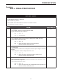
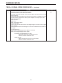
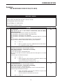
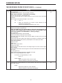
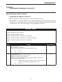
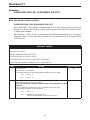
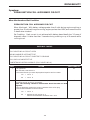
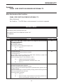
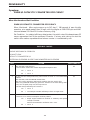
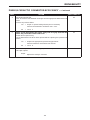
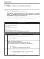
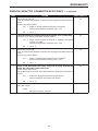
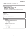
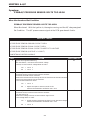
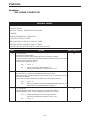
Symptom:
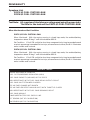
P0622-GENERATOR FIELD NOT SWITCHING PROPERLY
When Monitored and Set Condition:
P0622-GENERATOR FIELD NOT SWITCHING PROPERLY
When Monitored:
Set Condition:
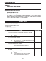
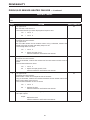
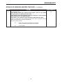
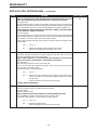
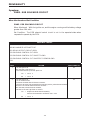
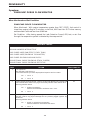
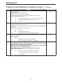
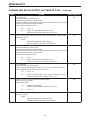
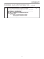
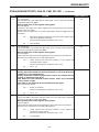
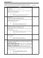
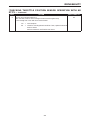
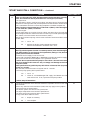
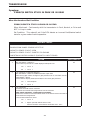
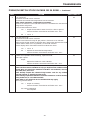
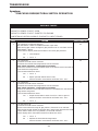
monitoring.
With the ignition key on and the engine running.
When the PCM tries to regulate the generator field with no result during
POSSIBLE CAUSES
GENERATOR FIELD WIRING HARNESS INTERMITTENT PROBLEM
GENERATOR FIELD WIRING HARNESS OBSERVABLE PROBLEM
ASD RELAY OUTPUT CIRCUIT OPEN
GENERATOR FIELD DRIVER CIRCUIT OPEN
GENERATOR FIELD DRIVER CIRCUIT SHORTED TO GROUND
GENERATOR FIELD RESISTANCE >= 5.0 OHMS
POWERTRAIN CONTROL MODULE
TEST
ACTION
APPLICABILITY
1
Ignition On, Engine Not Running
With the DRB actuate the Generator Field Driver Circuit.
Using a 12-volt test light, backprobe the Generator Field Driver Circuit at the back
of the Generator.
Did the light blink?
All
2
3
Yes
→ Go To
2
No
→ Go To
4
Ignition On, Engine Not Running
With the DRB actuate the Generator Field Driver Circuit.
Note: Actuator Test should still be running.
Wiggle Wiring Harness from the Generator to PCM.
With the DRB, read Codes.
Does the Generator Field Driver (-) Circuit code return?
Yes
→ Repair as necessary where wiggling caused problem to appear.
Perform the Powertrain Verification Test - Ver 3
No
→ Go To
All
3
Turn ignition off.
Using the schematic as a guide, inspect the Wiring and Connectors.
Were any problems found?
Yes
→ Repair as necessary.
Perform the Powertrain Verification Test - Ver 3
No
→ Test Complete.
16
All
CHARGING
P0622-GENERATOR FIELD NOT SWITCHING PROPERLY —
Continued
TEST
ACTION
APPLICABILITY
4
Ignition On, Engine Not Running
Record all DTC’s and freeze frame data, now erase Codes.
Carefully inspect all Connectors for corrosion or spread Terminals before continuing.
With the DRB actuate the Generator Field Driver Circuit.
Backprobe the ASD Relay Output Circuit at back of Generator.
Is the voltage above 10.0 volts?
All
5
6
7
8
Yes
→ Go To
No
→ Repair the open ASD Relay Output Circuit.
Perform the Powertrain Verification Test - Ver 3
5
Turn ignition off.
Disconnect the PCM Connectors.
Disconnect the Generator Field harness connector.
Using an Ohmmeter, measure the Generator Field Driver Circuit from PCM
Connector to ground.
Is the resistance below 5.0 ohms?
Yes
→ Repair the Generator Field Driver Circuit shorted to ground.
Perform the Powertrain Verification Test - Ver 3
No
→ Go To
All
6
Turn ignition off.
Disconnect the PCM harness connectors.
Disconnect the Generator Field harness connector.
Note: Check Connectors - Clean/repair as necessary.
Using an Ohmmeter, measure the Generator Field Driver Circuit from PCM to
Generator.
Is the resistance below 5.0 ohms?
Yes
→ Go To
No
→ Repair the open Generator Field Driver Circuit.
Perform the Powertrain Verification Test - Ver 3
All
7
Turn ignition off.
Disconnect the Generator Field harness connector at back of the Generator.
Note: Check connectors - Clean/repair as necessary.
Use an Ohmmeter in the following steps.
Measure resistance across the Generator Field Terminals at the Generator.
Is the resistance below 5.0 ohms?
Yes
→ Repair the Generator as necessary.
Perform the Powertrain Verification Test - Ver 3
No
→ Go To
All
8
If there are no possible causes remaining, replace the Powertrain Control Module.
View repair options.
Repair
Replace the Powertrain Control Module.
Perform the Powertrain Verification Test - Ver 3
17
All
CHARGING
Symptom:
P1478-BATTERY TEMP SENSOR VOLTS OUT OF LIMIT
When Monitored and Set Condition:
P1478-BATTERY TEMP SENSOR VOLTS OUT OF LIMIT
When Monitored:
Ignition on.
Set Condition: The Battery Temperature Sensor, internal to the PCM, goes above 4.9
volts or below 0.1 volt for more than 3.2 seconds.
POSSIBLE CAUSES
PCM DEFECTIVE
TEST
ACTION
APPLICABILITY
1
The Powertrain Control Module is reporting an internal trouble code and must be
replaced.
View repair options.
All
Repair
Replace the Powertrain Control Module.
18
CHARGING
Symptom List:
P1492-AMBIENT/BATT TEMP SEN VOLTS TOO HIGH
P1493-AMBIENT/BATT TEMP SEN VOLTS TOO LOW
Test Note:
All symptoms listed above are diagnosed using the same tests.
The title for the tests will be P1492-AMBIENT/BATT TEMP
SEN VOLTS TOO HIGH.
When Monitored and Set Condition:
P1492-AMBIENT/BATT TEMP SEN VOLTS TOO HIGH
When Monitored: With the ignition key on, the Body Control Module (BCM) transmits
temperature data to the PCM via the J1850 bus circuit.
Set Condition:
The PCM senses abnormally high or low voltage on its input.
P1493-AMBIENT/BATT TEMP SEN VOLTS TOO LOW
When Monitored: With the ignition key on, the Body Control Module (BCM) transmits
temperature data to the PCM via the J1850 bus circuit.
Set Condition:
The PCM senses abnormally high or low voltage on its input.
POSSIBLE CAUSES
WIRING HARNESS INTERMITTENT
AMBIENT TEMPERATURE SENSOR SIGNAL CIRCUIT OPEN
AMBIENT TEMPERATURE SENSOR SIGNAL CIRCUIT SHORTED TO GROUND
AMBIENT TEMPERATURE SENSOR SIGNAL CIRCUIT SHORTED TO THE SENSOR GROUND
CIRCUIT
SENSOR GROUND CIRCUIT OPEN
SENSOR GROUND CIRCUIT OPEN PARTIALLY SHORTED TO GROUND
AMBIENT TEMPERATURE SENSOR DEFECTIVE
BCM
BCM
TEST
1
ACTION
Turn ignition on.
With the DRBIIIt, read DTC’s.
Is the DTC Global Good Trip Counter displayed and equal to zero?
Yes
→ Go To
2
No
→ Go To
11
19
APPLICABILITY
All
CHARGING
P1492-AMBIENT/BATT TEMP SEN VOLTS TOO HIGH —
Continued
TEST
ACTION
APPLICABILITY
2
Disconnect the Ambient Temperature Sensor.
Remove the Ambient Temperature Sensor.
Using an ohmmeter, measure the resistance of the Ambient Temperature Sensor
across the Sensor.
Compare the readings with the Ambient Temp Sensor Specifications on the chart.
Do the readings compare with the values listed?
All
3
4
5
Yes
→ Go To
No
→ Replace the Ambient Temperature Sensor.
Perform the Powertrain Verification Test - Ver 5
3
Turn the ignition off.
Disconnect the Ambient Temperature Sensor connector.
Close all doors , insure all lights are off, then wait one minute.
Measure the resistance of the sensor ground circuit to ground.
Is the resistance below 30 ohms?
No
→ Go To
4
Yes
→ Go To
6
Turn ignition off.
Disconnect the Ambient Temperature Sensor connector.
Disconnect the BCM connector.
Measure the resistance of the Sensor Ground circuit between the Ambient Temperature Sensor connector and the BCM.
Is the resistance below 5.0 ohms?
No
→ Repair the open Sensor Ground circuit.
Perform the Powertrain Verification Test - Ver 5
Yes
→ Go To
All
All
5
If there are no possible causes remaining, replace the BCM.
View repair options.
All
Repair
Replace the BCM.
Perform the Powertrain Verification Test - Ver 5
6
Turn ignition off.
Disconnect the Ambient Temperature Sensor connectors.
Disconnect the BCM connectors.
Using an Ohmmeter, measure the resistance of the Ambient Temperature Sensor
Signal circuit from the Sensor connector to the BCM connector.
Is the resistance below 5.0 ohms?
No
→ Repair the open circuit.
Perform the Powertrain Verification Test - Ver 5
Yes
→ Go To
7
20
All
CHARGING
P1492-AMBIENT/BATT TEMP SEN VOLTS TOO HIGH —
Continued
TEST
ACTION
APPLICABILITY
7
Turn ignition off.
Disconnect the Ambient Temperature Sensor connector.
Disconnect the BCM connector.
Using an Ohmmeter, measure the resistance between the Sensor Ground circuit and
ground at the BCM.
Is the resistance below 500K (500,000) ohms?
All
8
9
10
No
→ Go To
Yes
→ Repair the Sensor Ground circuit for a partial short to ground.
Perform the Powertrain Verification Test - Ver 5
8
Turn ignition off.
Disconnect the Ambient Temperature Sensor connector.
Disconnect the BCM connector.
Using an Ohmmeter, measure the Ambient Temperature Sensor Signal circuit to
ground.
Is the resistance below 50K (50,000) ohms?
Yes
→ Repair the Ambient Temperature Sensor signal circuit for a
partial short to ground.
Perform the Powertrain Verification Test - Ver 5
No
→ Go To
All
9
Turn ignition off.
Disconnect the Ambient Temperature Sensor connector.
Disconnect the BCM connector.
Using an Ohmmeter, measure the resistance between the Ambient Temperature
Sensor Signal circuit and the Sensor Ground circuit.
Is the resistance below 50K (50,000) ohms?
Yes
→ Repair the Ambient Temperature Sensor Signal Circuit for a
short to the Sensor Ground Circuit.
Perform the Powertrain Verification Test - Ver 5
No
→ Go To
All
10
If there are no possible causes remaining, replace the BCM.
View repair options.
All
Repair
Replace the BCM.
Perform the Powertrain Verification Test - Ver 5
11
Turn ignition off.
Note: Visually inspect the related wiring harness. Look for any chafed,
pierced, pinched, or partially broken wires.
Note: Visually inspect the related wire harness connectors. Look for broken,
bent, pushed out, or corroded terminals.
Note: Refer to any Technical Service Bulletins (TSB) that may apply.
Were any problems found?
Yes
→ Repair wiring harness/connectors as necessary.
Perform the Powertrain Verification Test - Ver 5
No
→ Test Complete.
21
All
CHARGING
Symptom:
P1594-CHARGING SYSTEM VOLTAGE TOO HIGH
When Monitored and Set Condition:
P1594-CHARGING SYSTEM VOLTAGE TOO HIGH
When Monitored:
With the ignition key on and the engine speed greater than 380 RPM.
Set Condition: When the PCM regulates the generator field and there are no detected
field problems, but the voltage output does not decrease.
POSSIBLE CAUSES
GENERATOR FIELD DRIVER CIRCUIT SHORTED TO GROUND
GENERATOR FIELD SHORTED TO GROUND
PCM (BATTERY TEMPERATURE)
POWERTRAIN CONTROL MODULE (BATTERY VOLTAGE)
POWERTRAIN CONTROL MODULE (GENERATOR RESISTANCE)
TEST
ACTION
APPLICABILITY
1
Ignition On, Engine Not Running
With DRB, actuate the Generator Field Driver.
With a 12-volt test light, backprobe the Generator Field Driver Circuit in back of
Generator.
Did the light blink?
All
2
3
Yes
→ Go To
2
No
→ Go To
5
Ignition On, Engine Not Running
With the DRB, actuate the Generator Field Driver.
With DRB, stop the Generator Field Driver actuation.
With DRB, read the Target Charging voltage.
Is the Target Charging voltage above 13 volts?
Yes
→ Go To
3
No
→ Go To
4
Start the engine.
Manually set the engine speed to 1600 RPM.
With DRB, read both the Battery voltage and the Target Charging voltage.
Compare the 9Target Voltage9 to the 9Battery Voltage9 reading.
Monitor voltage for 5 minutes, if necessary. Look for a 1.0 volt difference or more.
Was there more than a 1.0 volt difference?
Yes
→ Replace the Powertrain Control Module.
Perform the Powertrain Verification Test - Ver 3
No
→ Test Complete.
22
All
All
CHARGING
P1594-CHARGING SYSTEM VOLTAGE TOO HIGH —
Continued
TEST
ACTION
APPLICABILITY
4
Turn ignition off.
Note: Battery must be fully charged.
Note: Generator Belt tension and condition must be checked before continuing.
Start engine and allow it to reach operating temperature.
With the DRB, read the BTS temperature.
Using a Thermometer, measure under hood temperature.
Is the temperature within 10 F degrees of Battery temperature?
All
5
6
7
Yes
→ Test Complete.
No
→ Replace Powertrain Control Module.
Perform the Powertrain Verification Test - Ver 3
Turn ignition off.
Disconnect the PCM Connectors.
Disconnect the Generator Field harness connector.
Using an Ohmmeter, measure the Generator Field Driver Circuit from PCM
Connector to ground.
Is the resistance below 5.0 ohms?
Yes
→ Repair the Generator Field Driver Circuit shorted to ground.
Perform the Powertrain Verification Test - Ver 3
No
→ Go To
All
6
Turn ignition off.
Disconnect the Field Harness Connector at back of the Generator.
Note: Check connectors - Clean/repair as necessary.
Measure resistance of the Generator Field Driver Circuit at the Generator to Ground.
Is the resistance below 5.0 ohms?
Yes
→ Repair or replace the shorted Generator as necessary.
Perform the Powertrain Verification Test - Ver 3
No
→ Go To
All
7
If there are no possible causes remaining, replace the Powertrain Control Module.
View repair options.
Repair
Replace the Powertrain Control Module.
Perform the Powertrain Verification Test - Ver 3
23
All
CHARGING
Symptom:
P1682-CHARGING SYSTEM VOLTAGE TOO LOW
When Monitored and Set Condition:
P1682-CHARGING SYSTEM VOLTAGE TOO LOW
When Monitored: With the ignition key on and the engine running over 1152 RPM. With
no other charging system codes set.
Set Condition: The battery sensed voltage is 1 volt below the charging goal for 25 seconds.
The PCM senses the battery Voltage turns off the field driver and senses the battery
voltage again. If the voltages are the same, the code is set.
POSSIBLE CAUSES
B (+) CIRCUIT HIGH RESISTANCE
GENERATOR GROUND HIGH RESISTANCE
ASD RELAY OUTPUT CIRCUIT OPEN
ASD RELAY OUTPUT CIRCUIT SHORTED TO GROUND
GENERATOR FIELD DRIVER CIRCUIT OPEN
GENERATOR FIELD DRIVER CIRCUIT SHORTED TO GROUND
PCM
PCM DEF (CHARGING SYSTEM VOLTAGE LOW)
TEST
ACTION
APPLICABILITY
1
Turn Ignition Off.
Note: Battery must be fully charged.
Note: Generator Belt tension and condition must be checked before continuing.
Start Engine.
With the DRB, read the target charging voltage.
Is the target charging voltage above 15.1 volts?
All
2
Yes
→ Go To
2
No
→ Go To
3
Turn ignition off.
Note: Battery must be fully charged.
Note: Generator Belt tension and condition must be checked before continuing.
Start engine and allow it to reach operating temperature.
With the DRB, read the BTS temperature.
Using a Thermometer, measure under hood temperature.
Is the temperature within 10 F degrees of Battery temperature?
Yes
→ Go To
No
→ Replace the PCM.
Perform the Powertrain Verification Test - Ver 3
3
24
All
CHARGING
P1682-CHARGING SYSTEM VOLTAGE TOO LOW —
Continued
TEST
ACTION
APPLICABILITY
3
Turn ignition on, engine not running.
Using a Voltmeter, measure voltage between the Generator B(+) Terminal and the
Battery (+) Post.
Caution: Ensure all wires are clear of the engine’s moving parts.
Start engine.
Is the voltage above 0.4 volt?
All
4
5
6
7
Yes
→ Repair the B(+) Circuit for high resistance between the Generator
and Battery.
Perform the Powertrain Verification Test - Ver 3
No
→ Go To
4
Start engine.
Warm the engine to operating temperature.
Caution: Ensure all wires are clear of the engine’s moving parts.
Using a Voltmeter, measure voltage between the Generator case and Battery (-) Post.
Is the voltage above 0.1 volt?
Yes
→ Repair Generator Ground for high resistance, Generator Case to
Battery (-) side.
Perform the Powertrain Verification Test - Ver 3
No
→ Go To
All
5
Start engine.
Turn on all accessories, manually set engine speed to 1600 RPM.
With DRB, read Target Charging and Charging voltage.
Compare the two readings.
Is there more than a 1.0 volt difference?
Yes
→ Go To
No
→ Test Complete.
All
6
Ignition On, Engine Not Running
With the DRB, actuate the Generator Field.
Using a Voltmeter, measure the voltage at both Generator Field Terminals.
Is the voltage below 3.0 volts at either Terminal?
Yes
→ Go To
No
→ Test Complete.
All
7
Ignition On, Engine Not Running
Record all DTC’s and freeze frame data, now erase Codes.
Carefully inspect all Connectors for corrosion or spread Terminals before continuing.
With the DRB actuate the Generator Field Driver Circuit.
Backprobe the ASD Relay Output Circuit at back of Generator.
Is the voltage above 10.0 volts?
Yes
→ Go To
No
→ Repair the open ASD Relay Output Circuit.
Perform the Powertrain Verification Test - Ver 3
8
25
All
CHARGING
P1682-CHARGING SYSTEM VOLTAGE TOO LOW —
Continued
TEST
ACTION
APPLICABILITY
8
Turn ignition off.
Disconnect the PCM Connectors.
Disconnect the Generator Field harness connector.
Using an Ohmmeter, measure the Generator Field Driver Circuit from PCM
Connector to ground.
Is the resistance below 5.0 ohms?
All
9
10
11
Yes
→ Repair the Generator Field Driver Circuit shorted to ground.
Perform the Powertrain Verification Test - Ver 3
No
→ Go To
9
Turn ignition off.
Disconnect ASD Relay Connector.
Note: Check connectors - Clean/repair as necessary.
Disconnect the generator field connector.
Note: Check Connectors - Clean/repair as necessary.
Using an Ohmmeter, measure the ASD Relay Output Circuit from ASD Relay
Connector to ground.
Is the resistance below 5.0 ohms?
Yes
→ Repair the ASD Relay Output Circuit shorted to ground.
Perform the Powertrain Verification Test - Ver 3
No
→ Go To
All
10
Turn ignition off.
Disconnect the PCM harness connectors.
Disconnect the Generator Field harness connector.
Note: Check Connectors - Clean/repair as necessary.
Using an Ohmmeter, measure the Generator Field Driver Circuit from PCM to
Generator.
Is the resistance below 5.0 ohms?
Yes
→ Go To
No
→ Repair the open Generator Field Driver Circuit.
Perform the Powertrain Verification Test - Ver 3
All
11
If there are no possible causes remaining, replace the Powertrain Control Module.
View repair options.
Repair
Replace the Powertrain Control Module.
Perform the Powertrain Verification Test - Ver 3
26
All
CHARGING
Symptom:
*CHECKING CHARGING SYSTEM OPERATION WITH NO DTC’S
PRESENT
POSSIBLE CAUSES
B (+) CIRCUIT HIGH RESISTANCE
GENERATOR GROUND HIGH RESISTANCE
B(+) CIRCUIT HIGH RESISTANCE (1.0 VOLT)
GENERATOR BELT OBSERVABLE PROBLEM
GENERATOR FIELD TERMINAL INTERMITTENT PROBLEM
TROUBLE CODES PRESENT
TROUBLE CODES PRESENT 2000 RPM
PCM (CHARGING SYSTEM NO CODE)
TEST
1
2
3
ACTION
Turn ignition off.
Note: Battery condition must be verified prior to this test.
Inspect the Generator Belt tension and condition.
Is the Generator Belt OK?
Yes
→ Go To
No
→ Repair as necessary.
Perform the Powertrain Verification Test - Ver 3
APPLICABILITY
All
2
Start the Engine.
Turn on all accessories.
Raise engine speed to 2000 RPM for 30 seconds then return to idle.
With the DRB III read DTC’s.
Are there any 9Charging System9 Trouble Codes?
Yes
→ Refer to Symptom list for problems related to Charging.
Perform the Powertrain Verification Test - Ver 3
No
→ Go To
All
3
Ignition On, Engine Not Running
With the DRB, actuate the Generator Field.
Using a 12-volt test light, backprobe the Generator Field Driver Terminal at the back
of the Generator.
Note: The test light should blink On and Off every 1.4 seconds.
While monitoring the 12-volt test light, wiggle the Field Terminals back to the PCM
and ASD Relay.
Was there any interruption in the normal cycle of the test light?
Yes
→ Repair the wire where wiggling interrupted the voltage cycle.
Perform the Powertrain Verification Test - Ver 3
No
→ Go To
4
27
All
CHARGING
*CHECKING CHARGING SYSTEM OPERATION WITH NO DTC’S
PRESENT — Continued
TEST
4
5
6
7
8
ACTION
Ignition On, Engine Not Running
With the DRB, read trouble codes.
Are there any 9Charging System9 trouble codes?
Yes
→ Refer to Symptom list for problems related to Charging.
Perform the Powertrain Verification Test - Ver 3
No
→ Go To
APPLICABILITY
All
5
Turn ignition on, engine not running.
Using a Voltmeter, measure voltage between the Generator B(+) Terminal and the
Battery (+) Post.
Caution: Ensure all wires are clear of the engine’s moving parts.
Start engine.
Is the voltage above 0.4 volt?
Yes
→ Repair the B(+) Circuit for high resistance between the Generator
and Battery.
Perform the Powertrain Verification Test - Ver 3
No
→ Go To
All
6
Start engine.
Warm the engine to operating temperature.
Caution: Ensure all wires are clear of the engine’s moving parts.
Using a Voltmeter, measure voltage between the Generator case and Battery (-) Post.
Is the voltage above 0.1 volt?
Yes
→ Repair Generator Ground for high resistance, Generator Case to
Battery (-) side.
Perform the Powertrain Verification Test - Ver 3
No
→ Go To
All
7
Ignition On, Engine Not Running.
With the DRB, read the Battery voltage and record the results.
Using a Voltmeter, measure Battery voltage B(+) to B(-) Terminal and record the
results.
Compare the two voltage readings.
Is the voltage difference less than one volt?
Yes
→ Test Complete.
No
→ Go To
All
8
Ignition On, Engine Not Running
With the DRB, read the Battery voltage and record the results.
Turn Ignition off.
Disconnect the PCM.
Note: Check connectors - Clean/repair as necessary.
Turn Ignition on, with the engine off.
Using a Voltmeter, measure the Fused B(+) at PCM Connector.
Is the voltage within one volt of the DRB recorded reading?
Yes
→ Go To
No
→ Repair the B(+) Circuit for high resistance between the PCM and
the Battery.
Perform the Powertrain Verification Test - Ver 3
9
28
All
CHARGING
*CHECKING CHARGING SYSTEM OPERATION WITH NO DTC’S
PRESENT — Continued
TEST
ACTION
APPLICABILITY
9
If there are no possible causes remaining, replace the Powertrain Control Module.
View repair options.
All
Repair
Replace the PCM.
Perform the Powertrain Verification Test - Ver 3
29
CHARGING
Symptom:
*CHECKING THE AMBIENT/BATTERY TEMPERATURE SENSOR
POSSIBLE CAUSES
WIRING HARNESS INTERMITTENT
BTS DEFECTIVE (OUT OF CALIBRATION)
TEST
ACTION
APPLICABILITY
1
Turn ignition off.
Note: Visually inspect the related wiring harness. Look for any chafed,
pierced, pinched, or partially broken wires.
Note: Visually inspect the related wire harness connectors. Look for broken,
bent, pushed out, or corroded terminals.
Note: Refer to any Technical Service Bulletins (TSB) that may apply.
Were any problems found?
All
2
Yes
→ Repair wiring harness/connectors as necessary.
Perform the Powertrain Verification Test - Ver 5
No
→ Go To
2
Turn ignition on.
With the DRB in sensors, read the 9Ambient/Bat Tmp Deg9 value and record the
reading.
Using a temp probe, measure the air temperature near the BTS.
Is the recorded BTS temperature value within 10° of the temperature probe reading?
Yes
→ Test Complete.
No
→ Replace the BTS.
Perform the Powertrain Verification Test - Ver 5
30
All
COMMUNICATION
Symptom List:
P0600-PCM FAILURE SPI COMMUNICATIONS
P0601-PCM INTERNAL CONTROLLER FAILURE
Test Note:
All symptoms listed above are diagnosed using the same tests.
The title for the tests will be P0600-PCM FAILURE SPI
COMMUNICATIONS.
When Monitored and Set Condition:
P0600-PCM FAILURE SPI COMMUNICATIONS
When Monitored:
Set Condition:
Ignition key on.
Internal Bus communication failure between processors.
P0601-PCM INTERNAL CONTROLLER FAILURE
When Monitored:
Set Condition:
Ignition key on.
Internal checksum for software failed, does not match calculated value.
POSSIBLE CAUSES
PCM (INTERNAL OR SPI)
TEST
ACTION
APPLICABILITY
1
The Powertrain Control Module is reporting internal errors and must be replaced.
View repair options.
All
Repair
Replace the Powertrain Control Module.
Perform Powertrain Verification Test VER-1A.
31
COMMUNICATION
Symptom:
P1685-INVALID SKIM KEY
When Monitored and Set Condition:
P1685-INVALID SKIM KEY
When Monitored:
At ignition key on.
Set Condition: This condition exists when the transponder ID (KEY) read by the SKIM
does not match any of the transponder ID’s stored in the SKIM’s memory. The following
could be new or does not match, PCM, SKIM, or KEY.
POSSIBLE CAUSES
INCORRECT VIN IN PCM
INVALID SKIM KEY NOT PRESENT
NO VIN PROGRAMMED IN THE PCM
PCM DEFECTIVE
SKIM TROUBLE CODES SET
TEST
1
2
3
4
ACTION
With the DRB read trouble codes. LOOK FOR P1685
Is the starts since set counter Zero, on the DRB DTC screen for code P1685?
Yes
→ Go To
2
No
→ Go To
7
Using the DRB, attempt to communicate with SKIM.
Can you communicate with the SKIM?
Yes
→ Go To
No
→ Refer to symptom *BUS +/- SIGNAL OPEN FROM SKIM in the
COMMUNICATION category.
APPLICABILITY
All
All
3
Using the DRB, check for trouble codes set in SKIM.
Are there any trouble codes set in the SKIM?
Yes
→ Repair all trouble codes set in SKIM first.
Perform Powertrain Verification Test VER-1A.
No
→ Go To
All
4
Note: If a VIN is not been programmed into the PCM, program VIN into PCM
and retest.
With the DRB, display the VIN that is programmed in the PCM.
Is the a VIN programmed in the PCM?
Yes
→ Go To
No
→ Program the correct VIN into the PCM and retest.
Perform Powertrain Verification Test VER-1A.
5
32
All
COMMUNICATION
P1685-INVALID SKIM KEY —
TEST
5
6
7
Continued
ACTION
With the DRB, display the VIN that is programmed in the PCM.
Is the correct VIN programmed in the PCM?
Yes
→ Go To
No
→ Replace the Powertrain Control Module (PCM) and program
correct VIN in the PCM and retest.
Perform Powertrain Verification Test VER-1A.
APPLICABILITY
All
6
All
Turn ignition off.
Replace the SKIM.
With the DRB, erase all DTC’s.
Attempt to start and idle the engine.
Using the DRB, read the PCM trouble codes.
Does the DRB display this code?
Yes
→ Replace the Powertrain Control Module.
Perform Powertrain Verification Test VER-1A.
No
→ Test Complete.
Note: This DTC could have been set if the SKIM module was disconnected,
or replaced recently.
Note: All keys that the customer uses for this vehicle must be tested to verify
they are good.
First verify the correct VIN is in both the PCM and SKIM modules.
Turn the Ignition key off.
With the next customer key turn the ignition key on and crank the engine to start.
If the engine starts that is usually a good key.
With the DRB read trouble codes. LOOK FOR P1685
Is the starts since set counter Zero, on the DRB DTC screen for code P1685?
Yes
→ Replace the Ignition Key.
Perform Powertrain Verification Test VER-1A.
No
→ Test Complete.
Note: If this DTC can not be reset, it could have been an actual theft attempt.
33
All
COMMUNICATION
Symptom:
P1686-NO SKIM BUS MESSAGE RECEIVED
When Monitored and Set Condition:
P1686-NO SKIM BUS MESSAGE RECEIVED
When Monitored:
At ignition key on and continuously during engine operation.
Set Condition: This condition exists when a SKIM status bus message was not received
from the SKIM module within the last 20 seconds.
POSSIBLE CAUSES
PCM DEFECTIVE
WIRING HARNESS INTERMITTENT DEFECT
PCI BUS CIRCUIT OPEN FROM PCM TO SKIM
TEST
1
2
3
ACTION
Turn ignition on, Engine not running.
With the DRB read PCM trouble codes. LOOK for P1686.
Is the starts since set counter on the DTC screen for P1686 equal to Zero?
Yes
→ Go To
2
No
→ Go To
4
Turn ignition on, Engine not running.
Connect the DRBIII and try to access the SKIM module.
With the DRB, select vehicle Theft Alarm and read SKIM Trouble Codes.
Note: This test will indicate if the Bus is operational from DLC to SKIM..
Were you able to establish communication to the SKIM?
Yes
→ Go To
No
→ Refer to symptom *BUS +/- SIGNAL OPEN FROM SKIM in the
COMMUNICATION category.
APPLICABILITY
All
All
3
Turn ignition off.
Disconnect the PCM.
Disconnect the SKIM.
Using an ohmmeter, measure the PCI Bus Circuit between the PCM and SKIM.
Is the resistance below 5.0 ohms?
Yes
→ Replace the Powertrain Control Module.
Perform Powertrain Verification Test VER-1A.
No
→ Repair the open PCI Bus Circuit.
Perform Powertrain Verification Test VER-1A.
34
All
COMMUNICATION
P1686-NO SKIM BUS MESSAGE RECEIVED —
Continued
TEST
ACTION
APPLICABILITY
4
Turn ignition off.
Note: Visually inspect the related wiring harness. Look for any chafed,
pierced, pinched, or partially broken wires.
Note: Visually inspect the related wire harness connectors. Look for broken,
bent, pushed out, or corroded terminals.
Note: Refer to any Technical Service Bulletins (TSB) that may apply.
Were any problems found?
All
Yes
→ Repair wiring harness/connectors as necessary.
Perform Powertrain Verification Test VER-1A.
No
→ Test Complete.
35
COMMUNICATION
Symptom:
P1687-NO CLUSTER BUS MESSAGE
When Monitored and Set Condition:
P1687-NO CLUSTER BUS MESSAGE
When Monitored:
Set Condition:
Ignition key on.
No messages received from the MIC (Instrument Cluster) for 20 seconds.
POSSIBLE CAUSES
INSTRUMENT CLUSTER DEFECTIVE
WIRING HARNESS INTERMITTENT DEFECT
PCI BUS CIRCUIT OPEN FROM PCM TO MIC
TEST
1
2
3
ACTION
Turn ignition on, Engine not running.
Using the DRB, erase codes.
Cycle the ignition key on and off several times.
With the DRB read PCM trouble codes. LOOK for P1687.
Did the 9No PCI Bus Message from MIC9 trouble code return?
Yes
→ Go To
3
No
→ Go To
2
Turn the ignition key on, Engine not running.
Does the Odometer in the Instrument Cluster display 9No Bus9?
Yes
→ Go To
3
No
→ Go To
4
Turn ignition off.
Disconnect the PCM.
Disconnect the Instrument Cluster Connector.
Using an ohmmeter, measure the PCI Bus Circuit between the PCM and the
Instrument Cluster Connector.
Is the resistance below 5.0 ohms?
Yes
→ Replace the Instrument Cluster.
Perform Powertrain Verification Test VER-1A.
No
→ Repair the open PCI Bus Circuit.
Perform Powertrain Verification Test VER-1A.
36
APPLICABILITY
All
All
All
COMMUNICATION
P1687-NO CLUSTER BUS MESSAGE —
Continued
TEST
ACTION
APPLICABILITY
4
Turn ignition off.
Note: Visually inspect the related wiring harness. Look for any chafed,
pierced, pinched, or partially broken wires.
Note: Visually inspect the related wire harness connectors. Look for broken,
bent, pushed out, or corroded terminals.
Note: Refer to any Technical Service Bulletins (TSB) that may apply.
Were any problems found?
All
Yes
→ Repair wiring harness/connectors as necessary.
Perform Powertrain Verification Test VER-1A.
No
→ Test Complete.
37
COMMUNICATION
Symptom:
P1695-NO CCD/J1850 MESSAGE FROM BODY CONTROL MODULE
When Monitored and Set Condition:
P1695-NO CCD/J1850 MESSAGE FROM BODY CONTROL MODULE
When Monitored: With the ignition on, engine running, auto transmission must be in
drive, and battery voltage greater than 10.0 volts.
Set Condition:
No messages recieved from the BCM for 20 seconds.
POSSIBLE CAUSES
BCM DEFECTIVE
FUSED B(+) CIRCUIT LESS THAN 10.0 VOLTS
FUSED IGNITION SWITCH OUTPUT CIRCUIT OPEN
PCM GROUND CIRCUIT(S) OPEN
WIRING HARNESS INTERMITTENT DEFECT
PCI BUS CKT OPEN
PCM DEFECTIVE
TEST
1
2
3
ACTION
Turn the ignition on.
With the DRBIIIt, read DTC’s.
Is the 9Starts Since Set9 counter displayed and equal to one or below.
Yes
→ Go To
2
No
→ Go To
8
Note: If the BUS is not operational, it will display on the odometer.
Does the odometer display 9No Bus9?
Yes
→ Refer to symptom *PCI BUS COMMUNICATION FAILURE in
the COMMUNICATION category.
No
→ Go To
APPLICABILITY
All
All
3
Turn ignition off.
Disconnect the Powertrain Control Module Connector.
Note: Check connectors - Clean/repair as necessary.
Turn the ignition key on.
Use a 12 volt test light in the following step.
With the 12V test light connected to ground, probe the Fused Ignition in the PCM
Connector.
Is the test light illuminated and bright?
Yes
→ Go To
No
→ Repair the open or high resistance Fused Ignition Switch Output
Circuit between PCM & Ignition Switch.
Perform the Powertrain Verification Test - Ver 1.
4
38
All
COMMUNICATION
P1695-NO CCD/J1850 MESSAGE FROM BODY CONTROL MODULE —
Continued
TEST
4
5
6
ACTION
Turn the Ignition Off.
Disconnect the Powertrain Control Module Connector.
Note: Check connectors - Clean/repair as necessary.
Use a 12 volt test light in the following step.
Connect the test light to Ground. Probe the B(+) Circuit in the PCM Connector.
Is the test light illuminated and bright?
No
→ Repair the fused B+ circuit for High resistance. If open circuit
PCM will show 9NO RESPONSE9
Perform Powertrain Verification Test VER-1A.
Yes
→ Go To
All
5
Turn ignition off.
Disconnect the Powertrain Control Module Connector.
Note: Check connectors - Clean/repair as necessary.
Use a 12 volt test light in the following step.
Connect 12V test light to B(+). Probe the Ground Circuits, one at a time, in the PCM
Connector.
Was the light illuminated and bright in each circuit?
Yes
→ Go To
No
→ Repair the ground(s) for an open or high resistance at the
Powertrain Control Module.
Perform the Powertrain Verification Test - Ver 1.
All
6
With the DRB, read PCM Diagnostic Trouble Codes. This is to ensure power and
grounds to the PCM are operational.
Note: If the DRB will not read PCM DTC’s, follow the (NO RESPONSE TO
PCM (SCI only)( symptom path, if vehicle will start. For NO START Conditions follow symptom (NO RESPONSE( in Starting catagory .
Turn the ignition off.
Disconnect the PCM harness connector.
Connect the DRB to the Data Link connector
Use Scope input cable CH7058, Cable to Probe adapter CH7062, and the red and
black test probes.
Connect the scope input cable to the channel one connector on the DRB. Attach the
red and black leads and the cable to probe adapter to the scope input cable.
Select DRB Standalone.
Select lab scope.
Select Live.
Select 12 volt square wave.
Press F2 for Scope.
Press F2 and use the down arrow to set voltage range to 20 volts. Press F2 again
when complete.
Connect the Black lead to the PCM ground. Connect the Red lead to the PCM PCI
Bus circuit
Turn the ignition on.
Observe the the voltage displayed on the DRB Lab Scope.
What is the voltage displayed on the scope?
Pulse from 0 to approximately 7.5 volts
Replace the Powertrain Control Module.
Perform Powertrain Verification Test VER-1A.
Steady 0 volts
Go To
APPLICABILITY
7
39
All
COMMUNICATION
P1695-NO CCD/J1850 MESSAGE FROM BODY CONTROL MODULE —
Continued
TEST
7
8
ACTION
Turn the ignition off.
Disconnect the PCM harness connector.
Disconnect the BCM harness connector.
Measure the resistance of the PCI Bus circuit from the PCM to the BCM.
Is the resistance below 5.0 ohms?
Yes
→ Replace the BCM.
Perform Powertrain Verification Test VER-1A.
No
→ Repair the open PCI Bus circuit.
Perform Powertrain Verification Test VER-1A.
Turn ignition off.
Note: Visually inspect the related wiring harness. Look for any chafed,
pierced, pinched, or partially broken wires.
Note: Visually inspect the related wire harness connectors. Look for broken,
bent, pushed out, or corroded terminals.
Note: Refer to any Technical Service Bulletins (TSB) that may apply.
Were any problems found?
Yes
→ Repair wiring harness/connectors as necessary.
Perform Powertrain Verification Test VER-1A.
No
→ Test Complete.
40
APPLICABILITY
All
All
COMMUNICATION
Symptom:
P1696-PCM FAILURE EEPROM WRITE DENIED
When Monitored and Set Condition:
P1696-PCM FAILURE EEPROM WRITE DENIED
When Monitored:
Ignition key on, Continuous.
Set Condition: An attempt to program/write to the internal EEPROM failed, Also checks
at powerdown.
POSSIBLE CAUSES
COMPARE SRI MILEAGE WITH ODOMETER
DRB DISPLAYS 9SRI MILEAGE INVALID9
DRB DISPLAYS WRITE REFUSED 2ND TIME
TEST
1
2
3
4
ACTION
With the DRB, perform the SRI Memory Test.
Does the DRB display 9Write Refused9?
Yes
→ Go To
2
No
→ Go To
3
APPLICABILITY
All
With the DRB, perform the SRI Memory Test a second time.
Note: Retest the SRI Memory two more times.
Does the DRB display 9Write Refused9 again?
Yes
→ Replace the Powertrain Control Module.
Perform Powertrain Verification Test VER-1A.
No
→ Test Complete.
With the DRB, perform the SRI Memory Test.
Does the DRB display 9SRI Mileage Invalid9?
All
All
Yes
→ Update the mileage and retest the SRI Memory.
Perform Powertrain Verification Test VER-1A.
No
→ Go To
4
Compare the SRI Mileage stored with the Instrument Panel Odometer.
Is the mileage within the specified range displayed on the DRB?
Yes
→ Test Complete.
No
→ Update the mileage and retest the SRI Memory.
Perform Powertrain Verification Test VER-1A.
41
All
COMMUNICATION
Symptom:
P1697-PCM FAILURE SRI MILE NOT STORED
When Monitored and Set Condition:
P1697-PCM FAILURE SRI MILE NOT STORED
When Monitored:
Ignition key on, Continuous.
Set Condition: An attempt to program/write to the internal EEPROM failed, Also checks
at powerdown.
POSSIBLE CAUSES
DRB DISPLAYS 9WRITE FAILURE9
COMPARE SRI MILEAGE WITH ODOMETER
DRB DISPLAYS 9SRI MILEAGE INVALID9
DRB DISPLAYS WRITE REFUSED 2ND TIME
TEST
1
2
3
4
ACTION
With the DRB, perform the SRI Memory Test.
Does the DRB display 9Write Failure9?
APPLICABILITY
All
Yes
→ Replace the Powertrain Control Module.
Perform Powertrain Verification Test VER-1A.
No
→ Go To
2
With the DRB, perform the SRI Memory Test.
Does the DRB display 9Write Refused9?
Yes
→ Go To
3
No
→ Go To
4
All
With the DRB, perform the SRI Memory Test a second time.
Note: Retest the SRI Memory two more times.
Does the DRB display 9Write Refused9 again?
Yes
→ Replace the Powertrain Control Module.
Perform Powertrain Verification Test VER-1A.
No
→ Test Complete.
With the DRB, perform the SRI Memory Test.
Does the DRB display 9SRI Mileage Invalid9?
All
All
Yes
→ Update the mileage and retest the SRI Memory.
Perform Powertrain Verification Test VER-1A.
No
→ Go To
5
42
COMMUNICATION
P1697-PCM FAILURE SRI MILE NOT STORED —
TEST
5
Continued
ACTION
Compare the SRI Mileage stored with the Instrument Panel Odometer.
Is the mileage within the specified range displayed on the DRB?
Yes
→ Test Complete.
No
→ Update the mileage and retest the SRI Memory.
Perform Powertrain Verification Test VER-1A.
43
APPLICABILITY
All
COMMUNICATION
Symptom:
P1698-NO BUS MESSAGE FROM TRANS CONTROL MODULE
When Monitored and Set Condition:
P1698-NO BUS MESSAGE FROM TRANS CONTROL MODULE
When Monitored: Equipped with automatic transmission, the ignition key on, engine
running, transmission in drive, vehicle road speed and battery voltage greater than 10
volts.
Set Condition:
No bus messages from the TCM for 10 seconds, two trips required.
POSSIBLE CAUSES
FUSED B(+) CIRCUIT LESS THAN 10.0 VOLTS
FUSED IGNITION SWITCH OUTPUT CIRCUIT OPEN
PCM GROUND CIRCUIT(S) OPEN
PCM INTERNAL PCI BUS OPEN
PCM PCI BUS CIRCUIT OPEN
WIRING HARNESS INTERMITTENT DEFECT
TEST
1
ACTION
Turn ignition on, Engine not running.
With the DRB read PCM trouble codes. LOOK for P1698.
Is the Starts since Set counter on the screen for DTC P1698 equal to Zero?
Yes
→ Go To
2
No
→ Go To
9
APPLICABILITY
All
Note: This DTC could have been set when the TCM is disconnected for
transmission Diagnostics.
2
Turn ignition on, Engine not running.
Connect the DRBIII and access Powertrain Control Module.
Note: This test checks for other PCI BUS codes. That indicates diferent
circuits in the BUS.
With the DRB read PCM trouble codes.
Is a DTC also set for NO SKIM BUS MESSAGE and/or No MIC BUS MESSAGE?
Yes
→ Go To
No
→ Refer to symptom *NO RESPONSE FROM TCM in the COMMUNICATION category.
3
44
All
COMMUNICATION
P1698-NO BUS MESSAGE FROM TRANS CONTROL MODULE — Continued
TEST
ACTION
APPLICABILITY
3
Turn Ignition On.
Note: As soon as one or more module communicates with the DRBIII,
answer the question.
With the DRBIII, Select THEFT ALARM, then select SKIM.
With the DRBIII, Select THEFT ALARM, Then select VTSS.
With the DRBIII, Select ANTI-LOCK BRAKES.
With the DRBIII, Select BODY, Then Select ELECTRO-MECHANICAL CLUSTER
(MIC).
With the DRBIII, Select PASSIVE RESTRAINTS, Then select AIRBAG.
Were you able to establish communication with any of the modules?
All
4
5
6
Yes
→ Go To
No
→ Refer to symptom *PCI BUS COMMUNICATION FAILURE in
the COMMUNICATION category.
4
Turn ignition off.
Disconnect the Powertrain Control Module Connector.
Note: Check connectors - Clean/repair as necessary.
Turn the ignition key on.
Use a 12 volt test light in the following step.
With the 12V test light connected to ground, probe the Fused Ignition in the PCM
Connector.
Is the test light illuminated and bright?
Yes
→ Go To
No
→ Repair the open or high resistance Fused Ignition Switch Output
Circuit between PCM & Ignition Switch.
Perform the Powertrain Verification Test - Ver 1.
All
5
Turn the Ignition Off.
Disconnect the Powertrain Control Module Connector.
Note: Check connectors - Clean/repair as necessary.
Use a 12 volt test light in the following step.
Connect the test light to Ground. Probe the B(+) Circuit in the PCM Connector.
Is the test light illuminated and bright?
No
→ Repair the fused B+ circuit for High resistance. If open circuit
PCM will show 9NO RESPONSE9
Perform Powertrain Verification Test VER-1A.
Yes
→ Go To
All
6
Turn ignition off.
Disconnect the Powertrain Control Module Connector.
Note: Check connectors - Clean/repair as necessary.
Use a 12 volt test light in the following step.
Connect 12V test light to B(+). Probe the Ground Circuits, one at a time, in the PCM
Connector.
Was the light illuminated and bright in each circuit?
Yes
→ Go To
No
→ Repair the ground(s) for an open or high resistance at the
Powertrain Control Module.
Perform the Powertrain Verification Test - Ver 1.
7
45
All
COMMUNICATION
P1698-NO BUS MESSAGE FROM TRANS CONTROL MODULE — Continued
TEST
ACTION
APPLICABILITY
7
With the DRB read PCM Diagnostic Trouble Codes. This is to ensure power and
grounds to the PCM are operational.
Note: If the DRB will not read PCM DTC’s, follow the (NO RESPONSE TO
PCM (SCI only)( symptom path, if vehicle will start. For NO START Conditions follow symptom (NO RESPONSE( in Starting catagory .
Turn ignition off.
Disconnect the Powertrain Control Module.
Connect the DRBIII to the Data Link connector
Use Scope input cable CH7058, Cable to Probe adapter CH7062, and the red and
black test probes.
Connect the scope input cable to the channel one connector on the DRB. Attach the
red and black leads and the cable to probe adapter to the scope input cable.
Select DRB Standalone.
Select lab scope.
Select Live.
Select 12 volt square wave.
Press F2 for Scope.
Press F2 and use the down arrow to set voltage range to 20 volts. Press F2 again
when complete.
Connect the Black lead to the PCM ground. Connect the Red lead to the PCM PCI
Bus circuit
Turn the ignition on.
Observe the the voltage displayed on the DRB Lab Scope.
What is the voltage displayed on the scope?
All
Pulse from 0 to approximately 7.5 volts
Go To 8
Steady 0 volts
Repair the open PCI Bus circuit to PCM.
Perform Powertrain Verification Test VER-1A.
8
The Powertrain Control Module has an internal open PCI Bus and must be replaced.
View repair options.
All
Repair
Replace the Powertrain Control Module.
Perform Powertrain Verification Test VER-1A.
9
Turn ignition off.
Note: Visually inspect the related wiring harness. Look for any chafed,
pierced, pinched, or partially broken wires.
Note: Visually inspect the related wire harness connectors. Look for broken,
bent, pushed out, or corroded terminals.
Note: Refer to any Technical Service Bulletins (TSB) that may apply.
Were any problems found?
Yes
→ Repair wiring harness/connectors as necessary.
Perform Powertrain Verification Test VER-1A.
No
→ Test Complete.
46
All
COMMUNICATION
Symptom:
*BUS +/- SIGNAL OPEN FROM SKIM
POSSIBLE CAUSES
SKIM RESPONSE FAILURE
PCI BUS OPEN CIRCUIT TO SKIM
SKIM FUSED B(+) OPEN
SKIM FUSED IGNITION SWITCH OUTPUT CIRCUIT OPEN
SKIM GROUND CIRCUIT OPEN
TEST
1
2
3
4
ACTION
Turn ignition on.
Using the DRB, attempt to communicate with SKIM.
Did you communicate with the SKIM?
No
→ Go To
Yes
→ Test Complete.
APPLICABILITY
All
2
Disconnect the SKIM connector.
Using a voltmeter, measure the Fused B(+) voltage at the SKIM connector.
Is the Fused B(+) above 10.0 volts?
Yes
→ Go To
No
→ Repair the open Fused B+ circuit to the SKIM.
Perform the SKIS Verification Test.
All
3
Disconnect the SKIM connector.
Turn Ignition on.
Using a voltmeter, measure the Fused Ignition Switch output voltage at the SKIM
connector.
Is the Fused Ignition Switch voltage above 10.0 volts?
Yes
→ Go To
No
→ Repair the open Fused Ignition Switch Output circuit.
Perform the SKIS Verification Test.
All
4
Disconnect the SKIM connector.
Using an ohmmmeter, measure the resistance between the SKIM ground circuit at
the SKIM connector and ground.
Is the resistance below 5.0 ohms?
Yes
→ Go To
No
→ Repair the open Sentry Key Immobilizer Module ground circuit.
Perform the SKIS Verification Test.
5
47
All
COMMUNICATION
*BUS +/- SIGNAL OPEN FROM SKIM —
Continued
TEST
ACTION
APPLICABILITY
5
Disconnect the Sentry Key Immobilizer Module.
Connect the DRB III to the Data Link connector.
Use Scope input cable CH7058, Cable to Probe adapter CH7062, and the red and
black test probes.
Connect the scope input cable to the channel one connector on the DRB III. Attach
the red and black leads and the cable to probe adapter to the scope input cable.
Select DRB Standalone.
Select lab scope.
Select Live.
Select 12 volt square wave.
Press F2 for Scope.
Press F2 and use the down arrow to set voltage range to 20 volts. Press F2 again
when complete.
Connect the Black lead to the SKIM ground. Connect the Red lead to the SKIM PCI
Bus circuit
Turn the ignition on.
Observe the voltage displayed on the DRB III Lab Scope.
What is the voltage displayed on the scope?
All
Pulse from 0 to approximately 7.5 volts
Replace the Sentry Key Immobilizer Module.
Perform the SKIS Verification Test.
Steady 0.0 volt
Repair the Open PCI BUS circuit to the SKIM.
Perform the SKIS Verification Test.
48
COMMUNICATION
Symptom:
*NO RESPONSE FROM PCM (PCI BUS)
POSSIBLE CAUSES
FUSED B(+) CIRCUIT LESS THAN 10.0 VOLTS
FUSED IGNITION SWITCH OUTPUT CIRCUIT OPEN
PCM GROUND CIRCUIT(S) OPEN
PCM INTERNAL PCI BUS OPEN
PCM PCI BUS CIRCUIT OPEN
TEST
ACTION
APPLICABILITY
1
Turn Ignition On.
Note: As soon as one or more module communicates with the DRBIII,
answer the question.
With the DRBIII, Select THEFT ALARM, then select SKIM.
With the DRBIII, Select THEFT ALARM, Then select VTSS.
With the DRBIII, Select ANTI-LOCK BRAKES.
With the DRBIII, Select BODY, Then Select ELECTRO-MECHANICAL CLUSTER
(MIC).
With the DRBIII, Select PASSIVE RESTRAINTS, Then select AIRBAG.
Were you able to establish communication with any of the modules?
All
2
3
Yes
→ Go To
No
→ Refer to symptom *PCI BUS COMMUNICATION FAILURE in
the COMMUNICATION category.
2
Turn ignition off.
Disconnect the Powertrain Control Module Connector.
Note: Check connectors - Clean/repair as necessary.
Turn the ignition key on.
Use a 12 volt test light in the following step.
With the 12V test light connected to ground, probe the Fused Ignition in the PCM
Connector.
Is the test light illuminated and bright?
Yes
→ Go To
No
→ Repair the open or high resistance Fused Ignition Switch Output
Circuit between PCM & Ignition Switch.
Perform the Powertrain Verification Test - Ver 1.
All
3
Turn the Ignition Off.
Disconnect the Powertrain Control Module Connector.
Note: Check connectors - Clean/repair as necessary.
Use a 12 volt test light in the following step.
Connect the test light to Ground. Probe the B(+) Circuit in the PCM Connector.
Is the test light illuminated and bright?
No
→ Repair the fused B+ circuit for High resistance. If open circuit
PCM will show 9NO RESPONSE9
Perform Powertrain Verification Test VER-1A.
Yes
→ Go To
4
49
All
COMMUNICATION
*NO RESPONSE FROM PCM (PCI BUS) —
Continued
TEST
ACTION
APPLICABILITY
4
Turn ignition off.
Disconnect the Powertrain Control Module Connector.
Note: Check connectors - Clean/repair as necessary.
Use a 12 volt test light in the following step.
Connect 12V test light to B(+). Probe the Ground Circuits, one at a time, in the PCM
Connector.
Was the light illuminated and bright in each circuit?
All
5
Yes
→ Go To
No
→ Repair the ground(s) for an open or high resistance at the
Powertrain Control Module.
Perform the Powertrain Verification Test - Ver 1.
5
With the DRB read PCM Diagnostic Trouble Codes. This is to ensure power and
grounds to the PCM are operational.
Note: If the DRB will not read PCM DTC’s, follow the (NO RESPONSE TO
PCM (SCI only)( symptom path, if vehicle will start. For NO START Conditions follow symptom (NO RESPONSE( in Starting catagory .
Turn ignition off.
Disconnect the Powertrain Control Module.
Connect the DRBIII to the Data Link connector
Use Scope input cable CH7058, Cable to Probe adapter CH7062, and the red and
black test probes.
Connect the scope input cable to the channel one connector on the DRB. Attach the
red and black leads and the cable to probe adapter to the scope input cable.
Select DRB Standalone.
Select lab scope.
Select Live.
Select 12 volt square wave.
Press F2 for Scope.
Press F2 and use the down arrow to set voltage range to 20 volts. Press F2 again
when complete.
Connect the Black lead to the PCM ground. Connect the Red lead to the PCM PCI
Bus circuit
Turn the ignition on.
Observe the the voltage displayed on the DRB Lab Scope.
What is the voltage displayed on the scope?
All
Pulse from 0 to approximately 7.5 volts
Go To 6
Steady 0 volts
Repair the open PCI Bus circuit to PCM.
Perform Powertrain Verification Test VER-1A.
6
The Powertrain Control Module has an internal open PCI Bus and must be replaced.
View repair options.
Repair
Replace the Powertrain Control Module.
Perform Powertrain Verification Test VER-1A.
50
All
COMMUNICATION
Symptom:
*NO RESPONSE FROM PCM (SCI ONLY)
POSSIBLE CAUSES
GROUND CIRCUIT(S) OPEN TO DATA LINK CONNECTOR
9NO RESPONSE9 DISPLAYED FROM DRB (SCI ONLY)
DRB
DRB ADAPTER CABLE
SCI RECEIVE CIRCUIT OPEN
SCI RECEIVE CIRCUIT SHORTED TO GROUND
SCI TRANSMIT CIRCUIT OPEN
SCI TRANSMIT CIRCUIT SHORTED TO GROUND
PCM (NO RESPONSE-START)
TEST
ACTION
APPLICABILITY
1
Turn ignition off.
Disconnect the DRB from the Data Link Connector.
Measure the resistance of each of the ground circuits between the data link connector
and a good ground.
Is the resistance below 5.0 ohms for both circuits?
All
2
3
4
Yes
→ Go To
No
→ Repair the open ground circuit(s).
Perform Powertrain Verification Test VER-1A.
2
With the DRB, attempt to read trouble codes.
Was the ignition on when the 9NO RESPONSE9 message was displayed?
Yes
→ Go To
No
→ Turn ignition on to get a response.
Perform Powertrain Verification Test VER-1A.
All
3
Substitute another DRB adapter cable.
With the DRB, attempt to read trouble codes.
Did the DRB display 9No Response9?
All
Yes
→ Go To
No
→ Replace the DRB Adapter Cable.
Perform Powertrain Verification Test VER-1A.
4
Turn ignition off.
Disconnect the Powertrain Control Module.
Disconnect DRB from the Data Link Connector (DLC).
Using an Ohmmeter, measure the resistance of the SCI Receive Circuit from the
PCM to the DLC.
Is the resistance below 5.0 ohms?
Yes
→ Go To
No
→ Repair the open SCI Receive Circuit.
Perform the Powertrain Verification Test - Ver 1.
5
51
All
COMMUNICATION
*NO RESPONSE FROM PCM (SCI ONLY) —
Continued
TEST
ACTION
APPLICABILITY
5
Turn ignition off.
Disconnect the Powertrain Control Module.
Disconnect DRB from the Data Link Connector (DLC).
Using an Ohmmeter, measure the resistance between the SCI Receive Circuit and
ground.
Is the resistance below 5.0 ohms?
All
6
7
8
9
Yes
→ Repair the SCI Receive Circuit for a short to ground.
Perform the Powertrain Verification Test - Ver 1.
No
→ Go To
6
Turn ignition off.
Disconnect the Powertrain Control Module.
Disconnect DRB from the Data Link Connector (DLC).
Using an Ohmmeter, measure the resistance of the SCI Transmit Circuit from the
PCM to the DLC.
Is the resistance below 5.0 ohms?
Yes
→ Go To
No
→ Repair the open SCI Transmit Circuit.
Perform the Powertrain Verification Test - Ver 1.
All
7
Turn ignition off.
Disconnect the Powertrain Control Module.
Disconnect DRB from the Data Link Connector (DLC).
Using an Ohmmeter, measure the resistance between the SCI Transmit Circuit and
ground.
Is the resistance below 5.0 ohms?
Yes
→ Repair the SCI Transmit Circuit for a short to ground.
Perform the Powertrain Verification Test - Ver 1.
No
→ Go To
All
8
Connect the DRB to a functional Data Link on another vehicle.
Turn ignition on.
With the DRB, attempt to read trouble codes.
Did the DRB display 9No Response9?
Yes
→ Go To
No
→ Replace the initial vehicle’s Powertrain Control Module.
Perform Powertrain Verification Test VER-1A.
All
9
If there are no potential causes remaining, repair or replace the DRB.
View repair options.
Repair
Have the DRB repaired or replaced.
Perform Powertrain Verification Test VER-1A.
52
All
COMMUNICATION
Symptom:
*NO RESPONSE FROM TCM
POSSIBLE CAUSES
FUSED IGNITION SWITCH OUTPUT (RUN/ST) CIRCUIT OPEN
FUSED IGNITION SWITCH OUTPUT (START) CIRCUIT OPEN
GROUND CIRCUIT OPEN
FUSED B(+) CIRCUIT TO TCM OPEN
OTHER BUS PROBLEMS PRESENT
PCI BUS CIRCUIT OPEN
TCM (PCI BUS CIRCUIT)
TEST
1
2
3
ACTION
With the DRBIIIt, attempt to read Transmission DTC’s.
Does the DRB show 9NO RESPONSE to TCM9?
Yes
→ Go To
No
→ Test Complete.
APPLICABILITY
All
2
With the DRBIII, check all of the other modules on the vehicle for evidence of a
vehicle bus problem.
Bus related DTC’s in other modules point to an overall vehicle bus problem. Other
symptoms such as a customer complaint of intermittent operation of bus controlled
features also indicate a bus problem.
Does the PRNDL display indicate 9No Bus9 or is there any evidence of an overall
vehicle bus problem?
Yes
→ Diagnose and repair other bus problems as necessary.
Perform the 42LE Transmission Verification Test - Ver 1.
No
→ Go To
All
3
Turn ignition off to the lock position.
Disconnect the Transmission Control Module (TCM).
Note: Check connectors - Clean/repair as necessary.
Connect the ground lead of a test light to a known good ground.
Turn the ignition on.
Using a 12-volt Test Light connected to ground, check the Fused Ignition Switch
Output (Run/St) circuit in the TCM connector.
Note: The light must illuminate brightly, if it does not light, or lights dimly,
the circuit must be repaired. If there is any doubt, compare the brightness
when testing the circuit, to the brightness when connected directly to the
battery positive post.
Does the test light illuminate brightly.
Yes
→ Go To
No
→ Repair cause of not lit or dim test light in Fused Ignition Switch
Output (Run/St) circuit.
Perform the 42LE Transmission Verification Test - Ver 1.
4
53
All
COMMUNICATION
*NO RESPONSE FROM TCM —
Continued
TEST
ACTION
APPLICABILITY
4
Turn ignition off to the lock position.
Disconnect the TCM connector.
Remove the starter relay from the PDC.
Connect the ground lead of a test light to a known good ground.
Using a 12-volt Test Light connected to ground, check the Fused Ignition Switch
Output (Start) circuit in the TCM connector.
Turn the ignition switch to the start position.
Note: The light must illuminate brightly, if it does not light, or lights dimly,
the circuit must be repaired. If there is any doubt, compare the brightness
when testing the circuit, to the brightness when connected directly to the
battery positive post.
Does the test light illuminate brightly.
All
Yes
→ Go To
No
→ Repair cause of unlit or dim test light in Fused Ignition Switch
Output (Start) circuit.
Perform the 42LE Transmission Verification Test - Ver 1.
5
Note: Reinstall the Starter Relay.
5
6
7
Turn ignition off to the lock position.
Disconnect the Transmission Control Module (TCM) harness connector.
Note: Check connectors - Clean/repair as necessary.
Connect the ground clip of a test light to a known good 12 volt source on the vehicle
such as the positive battery post.
Probe all ground circuit(s) in the TCM connector with the test light..
Does the light illuminate brightly at all ground circuits?
Yes
→ Go To
No
→ Repair the Ground circuit(s) as necessary.
Perform the 42LE Transmission Verification Test - Ver 1.
All
6
Turn ignition off to the lock position.
Disconnect the Transmission Control Module (TCM) harness connector.
Connect the ground clip of a test light to a known good ground.
Connect the other end to the Fused B(+) circuit in the TCM connector.
Does the test light illuminate brightly?
Yes
→ Go To
No
→ Repair Fused B(+) Circuit wiring and / or connectors.
Perform the 42LE Transmission Verification Test - Ver 1.
All
7
Turn ignition off to the lock position.
Disconnect the Transmission Control Module (TCM) harness connector.
Disconnect the Body Control Module (BCM) harness connector.
Note: Check connectors - Clean/repair as necessary.
Measure the resistance of the PCI Bus circuit from the TCM connector to the BCM
connector.
Is the resistance above 5.0 ohms?
Yes
→ Repair the open PCI Bus circuit between the TCM and the BCM.
Perform the 42LE Transmission Verification Test - Ver 1.
No
→ Go To
8
54
All
COMMUNICATION
*NO RESPONSE FROM TCM —
TEST
8
Continued
ACTION
TheTransmission Control Module has a bus problem and must be replaced.
View repair options.
Repair
Replace the Transmission Control Module.
Perform the 42LE Transmission Verification Test - Ver 1.
55
APPLICABILITY
All
COMMUNICATION
Symptom:
*PCI BUS COMMUNICATION FAILURE
POSSIBLE CAUSES
PCI BUS CIRCUIT SHORTED TO GROUND
PCI BUS CIRCUIT SHORTED TO VOLTAGE
HIGH VOLTAGE ON THE PCI BUS CIRCUITS AT THE BCM CONNECTORS
LOW RESISTANCE TO GROUND ON THE PCI BUS CIRCUITS AT THE BCM CONNECTORS
MODULE (PCI BUS SHORT TO GROUND)
MODULE (PCI BUS SHORT TO VOLTAGE)
BODY CONTROL MODULE
OPEN PCI BUS CIRCUIT BETWEEN THE DLC AND THE BCM
WIRING HARNESS INTERMITTENT
TEST
ACTION
APPLICABILITY
1
Note: When attempting to communicate with any of the modules on this
vehicle, the DRB will display 1 of 2 different communication errors: A (no
response( message or a (BUS +/- Signal Open( message.
Turn the ignition on.
With the DRB, attempt to communicate with the following modules: Body Control
Module (BCM), Instrument Cluster (MIC), Controller Anti-lock Brake (CAB), and the
Occupant Restraint Controller (ORC).
Was the DRB able to communicate with any of the modules listed?
All
2
3
Yes
→ Go To
2
No
→ Go To
3
Turn the ignition off.
Note: Visually inspect the related wiring harness. Look for any chafed,
pierced, pinched, or partially broken wires.
Note: Visually inspect the related wire harness connectors. Look for broken,
bent, pushed out, or corroded terminals.
Note: If the DRB can not communicate with a single module, refer to the
category list for the related symptom.
Were any problems found?
Yes
→ Repair wiring harness/connectors as necessary.
Perform the Body Verification Test - Ver 1.
No
→ Test Complete.
Attempt to start the vehicle.
Does the vehicle start and continue to run?
Yes
→ Go To
4
No
→ Go To
6
All
All
56
COMMUNICATION
*PCI BUS COMMUNICATION FAILURE —
Continued
TEST
ACTION
APPLICABILITY
4
Turn the ignition off.
Disconnect the BCM 9C19 harness connector.
Measure the resistance of the PCI Bus (DLC) circuit between the DLC connector and
the BCM 9C19 connector cavity 14.
Is the resistance below 5.0 ohms?
All
5
Yes
→ Go To
No
→ Repair the PCI Bus (DLC) circuit for an open.
Perform the Body Verification Test - Ver 1.
5
If there are no possible causes remaining, replace the BCM.
View repair options.
All
Repair
Replace the BCM.
Perform the Body Verification Test - Ver 1.
6
7
8
Note: Reconnect any previously disconnected components or connectors.
Turn the ignition on.
Measure the voltage of the PCI Bus circuit (DLC) in the Data Link connector.
Is the voltage steadily above 7.0 volts?
Yes
→ Go To
7
No
→ Go To
9
Note: Determine which modules this vehicle is equipped with before beginning.
Turn the ignition off.
Disconnect the BCM harness connectors and remove the Body Control Module from
the Junction Block.
Turn the ignition on.
Measure the voltage of each PCI Bus circuit at the BCM 9C19, 9C39, 9C49 connectors
and at the Junction Block Body Control Module connector cavity 10.
Is the voltage steadily above 7.0 volts for any measurement?
Yes
→ Go To
No
→ Replace the Body Control Module.
Perform the Body Verification Test - Ver 1.
All
All
8
Turn the ignition off.
Disconnect the module that corresponds to the PCI Bus circuit that measured
steadily above 7.0 volts.
Turn the ignition on.
Note: If the PCI Bus circuit for the Occupant Restraint Controller was
above 7.0 volts and is equipped with side airbags, disconnect each module
one at a time.
Measure the voltage of the PCI Bus circuit that previously measured above 7.0 volts.
Is the voltage steadily above 7.0 volts with the module disconnected?
Yes
→ Repair the PCI Bus circuit that measured over 7.0 volts for a
short to voltage.
Perform the Body Verification Test - Ver 1.
No
→ Replace the module that caused the short to voltage on the PCI
Bus circuit.
Perform the Body Verification Test - Ver 1.
57
All
COMMUNICATION
*PCI BUS COMMUNICATION FAILURE —
Continued
TEST
ACTION
APPLICABILITY
9
Note: Determine which modules this vehicle is equipped with before beginning.
Turn the ignition off.
Disconnect the negative battery cable.
Disconnect the BCM harness connectors and remove the Body Control Module from
the Junction Block.
Measure the resistance between ground and each of the PCI Bus circuits at the BCM
9C19, 9C39, 9C49 connectors and at the Junction Block Body Control Module connector
cavity 10.
Is the resistance below 100.0 ohms for any of the measurements?
All
10
Yes
→ Go To
No
→ Replace the Body Control Module.
Perform the Body Verification Test - Ver 1.
10
Turn the ignition off.
Disconnect the negative battery cable.
Disconnect the module that corresponds to the PCI Bus circuit that resistance
measured below 100.0 ohms.
Note: If the PCI Bus circuit for the Occupant Restraint Controller was
below 100.0 ohm and is equipped with side airbags, disconnect each module
one at a time.
Measure the resistance between ground and the PCI Bus circuit that previously
measured below 100.0 ohms.
Is the resistance below 100.0 ohms with the module disconnected?
Yes
→ Repair the PCI Bus circuit that resistance measured below 100.0
ohms for a short to ground.
Perform the Body Verification Test - Ver 1.
No
→ Replace the module that caused the short to ground on the PCI
Bus circuit.
Perform the Body Verification Test - Ver 1.
58
All
DRIVEABILITY
Symptom:
P0106-BAROMETRIC PRESSURE OUT OF RANGE
When Monitored and Set Condition:
P0106-BAROMETRIC PRESSURE OUT OF RANGE
When Monitored: With the ignition key on at less than 350 milliseconds and engine speed
at less than 255 RPM.
Set Condition: The PCM senses the voltage from the MAP sensor to be less than 2.196
volts but above 0.019 volts for 300 milliseconds.
POSSIBLE CAUSES
MAP SENSOR WIRING HARNESS INTERMITTENT
MAP SENSOR WIRING HARNESS OBSERVABLE PROBLEM
MAP SENSOR 5-VOLT SUPPLY CIRCUIT OPEN
MAP SENSOR 5-VOLT SUPPLY CIRCUIT SHORTED TO GROUND
MAP SENSOR SIGNAL CIRCUIT SHORTED TO SENSOR GROUND CIRCUIT
MAP SENSOR SIGNAL CIRCUIT HIGH RESISTANCE TO GROUND
MAP SENSOR SIGNAL CIRCUIT OPEN
MAP SENSOR
PCM
PCM DEFECTIVE
TEST
1
2
ACTION
Turn Ignition On.
With the DRB, read the DTC’s.
Is the Global Good Trip Counter displayed and equal to zero?
Yes
→ Go To
2
No
→ Go To
12
Turn ignition on.
With the DRB, read the MAP Sensor Voltage.
Is the voltage below 2.2 volts?
Yes
→ Go To
3
No
→ Go To
12
APPLICABILITY
All
All
59
DRIVEABILITY
P0106-BAROMETRIC PRESSURE OUT OF RANGE —
TEST
3
4
5
6
7
Continued
ACTION
Turn the ignition off.
Disconnect the MAP Sensor Connector.
Turn ignition on.
With the DRB, monitor the MAP Sensor Voltage.
Cycle the ignition switch from off to on.
Is the voltage above 4.9 volts?
Yes
→ Go To
4
No
→ Go To
8
Turn ignition on.
Disconnect the MAP Sensor Connector.
With a voltmeter, measure the 5 Volt Supply at the MAP Sensor Connector.
Is the voltage above 4.0 volts?
Yes
→ Replace the MAP Sensor.
Perform Powertrain Verification Test VER-5A.
No
→ Go To
APPLICABILITY
All
All
5
Turn the ignition off.
Disconnect the MAP Sensor harness connector.
Disconnect the Powertrain Control Module harness connector.
Note: Check connectors - Clean/repair as necessary.
Measure the resistance of the MAP Sensor 5-Volt Supply Circuit from the MAP
Sensor Connector to the PCM Connector.
Is the resistance below 5.0 ohms?
Yes
→ Go To
No
→ Repair the open 5-Volt Supply Circuit.
Perform the Powertrain Verification Test - Ver 5.
All
6
Turn ignition off.
Disconnect the MAP Sensor Electrical Connector.
Disconnect the Powertrain Control Module.
Note: Check connectors - Clean/repair as necessary.
With an Ohmmeter, measure the MAP Sensor 5-Volt Supply Circuit for resistance to
ground.
Is the resistance below 5.0 ohms?
Yes
→ Repair the 5-Volt Supply Circuit for a short to ground.
Perform the Powertrain Verification Test - Ver 5.
No
→ Go To
All
7
If there are no possible causes remaining, replace the PCM.
View repair options.
Repair
Replace the Powertrain Control Module.
Perform Powertrain Test Verification VER-5A.
60
All
DRIVEABILITY
P0106-BAROMETRIC PRESSURE OUT OF RANGE —
TEST
8
9
10
11
Continued
ACTION
Turn the ignition off.
Disconnect the MAP Sensor Connector.
Turn ignition on.
With the DRB, monitor the MAP Sensor Voltage.
Cycle the ignition switch from off to on.
Is the voltage between 2.2 and 4.9 volts?
Yes
→ Repair the high resistance to ground in the MAP sensor signal
circuit.
Perform Powertrain Test Verification VER-5A.
No
→ Go To
APPLICABILITY
All
9
Turn ignition off.
Disconnect the PCM.
Disconnect the MAP Sensor Electrical Connector.
Note: Check connectors - Clean/repair as necessary.
Using an Ohmmeter, Measure the MAP Sensor Signal Circuit for resistance between
the PCM Connector and the MAP Sensor Connector.
Is the resistance below 5.0 ohms?
Yes
→ Go To
No
→ Repair the open MAP Sensor Signal Circuit.
Perform Powertrain Test Verification VER-5A.
All
10
Turn the ignition off.
Disconnect the MAP Sensor harness connector.
Disconnect the Powertrain Control Module harness connector.
Note: Check connectors - Clean/repair as necessary.
Measure resistance between the MAP Sensor Signal Circuit and the MAP Sensor
Ground Circuit.
Is the resistance below 5.0 ohms?
Yes
→ Repair MAP Sensor Signal Circuit shorted to MAP Sensor
Ground Circuit.
Perform Powertrain Test Verification VER-5A.
No
→ Go To
All
11
If there are no possible causes remaining, replace the PCM.
View repair options.
All
Repair
Replace the Powertrain Control Module.
Perform Powertrain Test Verification VER-5A.
12
Turn ignition off.
Using the schematic as a guide, inspect the Wiring and Connectors.
Were any problems found?
Yes
→ Repair as necessary.
Perform Powertrain Test Verification VER-5A.
No
→ Go To
13
61
All
DRIVEABILITY
P0106-BAROMETRIC PRESSURE OUT OF RANGE —
TEST
13
Continued
ACTION
Warning: KEEP CLEAR OF THE ENGINE’S MOVING PARTS.
Start engine.
With the DRB, read the MAP Sensor voltage.
Wiggle MAP Sensor Connector & Harness.
Monitor the DRB display.
Was there any MAP Sensor voltage change?
Yes
→ Repair the Harness or Connector that caused the voltage change.
Perform Powertrain Test Verification VER-5A.
No
→ Test Complete.
62
APPLICABILITY
All
DRIVEABILITY
Symptom:
P0107-MAP SENSOR VOLTAGE TOO LOW
When Monitored and Set Condition:
P0107-MAP SENSOR VOLTAGE TOO LOW
When Monitored: With the engine RPM above 416 but less than 1500, the TPS voltage
less than 1.13 volts, and battery voltage greater than 10.4 volts.
Set Condition: The MAP sensor signal voltage is below 0.1 volt for 2.0 seconds with the
engine running.
POSSIBLE CAUSES
MAP SENSOR WIRING HARNESS INTERMITTENT
MAP SENSOR WIRING HARNESS OBSERVABLE PROBLEM
MAP SENSOR 5-VOLT SUPPLY CIRCUIT OPEN
MAP SENSOR 5-VOLT SUPPLY CIRCUIT SHORTED TO GROUND
MAP SENSOR SIGNAL CIRCUIT SHORTED TO SENSOR GROUND CIRCUIT
MAP SENSOR SIGNAL CIRCUIT SHORTED TO GROUND
MAP SENSOR
PCM (5-VOLT SUPPLY)
PCM (SIGNAL CIRCUIT)
TEST
1
2
ACTION
All
Start engine.
Let engine idle.
With the DRB, read the MAP Sensor voltage.
Is the MAP Sensor voltage below 0.6 volts?
Yes
→ Go To
3
No
→ Go To
2
Ignition On, Engine Not Running.
With the DRB, read the MAP Sensor voltage.
Is the MAP Sensor voltage below 3.19 volts?
Yes
→ Go To
3
No
→ Go To
11
APPLICABILITY
All
63
DRIVEABILITY
P0107-MAP SENSOR VOLTAGE TOO LOW —
TEST
3
4
5
6
7
Continued
ACTION
Turn ignition off.
Disconnect the MAP Sensor Electrical Connector.
Note: Check connectors - Clean/repair as necessary.
Ignition on, engine not running.
Use a Voltmeter in the following step.
Measure the MAP Sensor 5-Volt Supply Circuit.
Is the voltage above 4.5 volts?
Yes
→ Go To
4
No
→ Go To
8
Turn ignition off.
Disconnect the MAP Sensor Electrical Connector.
Note: Check connectors - Clean/repair as necessary.
Ignition on, engine not running.
Use the DRB to read MAP Sensor voltage.
Is the MAP Sensor voltage above 4.5 volts?
Yes
→ Replace the MAP Sensor.
Perform Powertrain Verification Test VER-5A.
No
→ Go To
APPLICABILITY
All
All
5
Turn the ignition off.
Disconnect the MAP Sensor harness connector.
Disconnect the Powertrain Control Module harness connector.
Note: Check connectors - Clean/repair as necessary.
Measure resistance between the MAP Sensor Signal Circuit and the MAP Sensor
Ground Circuit.
Is the resistance below 5.0 ohms?
Yes
→ Repair MAP Sensor Signal Circuit shorted to MAP Sensor
Ground Circuit.
Perform Powertrain Test Verification VER-5A.
No
→ Go To
All
6
Turn the ignition off.
Disconnect the MAP Sensor harness Connector.
Disconnect the Powertrain Control Module harness connector.
Note: Check connectors - Clean/repair as necessary.
Using an Ohmmeter, measure resistance of MAP Sensor Signal circuit to ground.
Is the resistance below 5.0 ohms?
Yes
→ Repair the MAP Sensor Signal Circuit for a short to ground.
Perform Powertrain Test Verification VER-5A.
No
→ Go To
All
7
If there are no possible causes remaining, replace the PCM.
View repair options.
Repair
Replace the Powertrain Control Module.
Perform Powertrain Test Verification VER-5A.
64
All
DRIVEABILITY
P0107-MAP SENSOR VOLTAGE TOO LOW —
Continued
TEST
ACTION
APPLICABILITY
8
Turn the ignition off.
Disconnect the MAP Sensor harness connector.
Disconnect the Powertrain Control Module harness connector.
Note: Check connectors - Clean/repair as necessary.
Measure the resistance of the MAP Sensor 5-Volt Supply Circuit from the MAP
Sensor Connector to the PCM Connector.
Is the resistance below 5.0 ohms?
All
9
10
Yes
→ Go To
No
→ Repair the open 5-Volt Supply Circuit.
Perform the Powertrain Verification Test - Ver 5.
9
Turn ignition off.
Disconnect the MAP Sensor Electrical Connector.
Disconnect the Powertrain Control Module.
Note: Check connectors - Clean/repair as necessary.
With an Ohmmeter, measure the MAP Sensor 5-Volt Supply Circuit for resistance to
ground.
Is the resistance below 5.0 ohms?
Yes
→ Repair the 5-Volt Supply Circuit for a short to ground.
Perform the Powertrain Verification Test - Ver 5.
No
→ Go To
All
10
If there are no possible causes remaining, replace the PCM.
View repair options.
All
Repair
Replace the Powertrain Control Module.
Perform Powertrain Test Verification VER-5A.
11
12
Turn ignition off.
Using the schematic as a guide, inspect the Wiring and Connectors.
Were any problems found?
Yes
→ Repair as necessary.
Perform Powertrain Test Verification VER-5A.
No
→ Go To
All
12
Warning: KEEP CLEAR OF THE ENGINE’S MOVING PARTS.
Start engine.
With the DRB, read the MAP Sensor voltage.
Wiggle MAP Sensor Connector & Harness.
Monitor the DRB display.
Was there any MAP Sensor voltage change?
Yes
→ Repair the Harness or Connector that caused the voltage change.
Perform Powertrain Test Verification VER-5A.
No
→ Test Complete.
65
All
DRIVEABILITY
Symptom:
P0108-MAP SENSOR VOLTAGE TOO HIGH
When Monitored and Set Condition:
P0108-MAP SENSOR VOLTAGE TOO HIGH
When Monitored: With the engine RPM above 400, the TP sensor voltage less than 1.13
volt, and battery voltage greater than 10.4 volts
Set Condition: The MAP sensor signal voltage is greater than 4.88 volts at start or with
the engine running for 2.2 seconds.
POSSIBLE CAUSES
MAP SENSOR GROUND CIRCUIT OPEN
MAP SENSOR WIRING HARNESS INTERMITTENT
MAP SENSOR WIRING HARNESS OBSERVABLE PROBLEM
MAP SENSOR SIGNAL CIRCUIT SHORTED TO BATTERY VOLTAGE
MAP SENSOR SIGNAL CIRCUIT OPEN
MAP SENSOR SIGNAL CIRCUIT SHORTED TO 5-VOLT SUPPLY CIRCUIT
MAP SENSOR
PCM (MAP SENSOR VOLTAGE TOO HIGH)
TEST
1
2
ACTION
Start the engine.
With the DRB, read the MAP Sensor voltage.
Is the MAP Sensor voltage above 4.6 volts?
Yes
→ Go To
2
No
→ Go To
8
APPLICABILITY
All
Ignition Off.
Disconnect the MAP Sensor harness connector.
Note: Check connectors - Clean/repair as necessary.
Connect a jumper wire between the Sensor Signal and Sensor Ground Circuits.
Turn ignition on, engine off.
With the DRB, read the MAP Sensor voltage.
Is the voltage below 1.0 volt?
Yes
→ Replace the MAP Sensor.
Perform Powertrain Verification Test VER-5A.
No
→ Go To
3
66
All
DRIVEABILITY
P0108-MAP SENSOR VOLTAGE TOO HIGH —
Continued
TEST
ACTION
APPLICABILITY
3
Ignition Off
Disconnect the MAP Sensor harness connector.
Note: Check connectors - Clean/repair as necessary.
Ignition on,Engine not running.
Using a Voltmeter measure the voltage of the MAP Sensor Signal Circuit at the MAP
Sensor Connector.
Is the voltage above 5.5 volts?
All
4
5
6
7
Yes
→ Repair the MAP Sensor Signal shorted to battery voltage.
Perform Powertrain Test Verification VER-5A.
No
→ Go To
4
Turn ignition off.
Disconnect the MAP Sensor harness connector.
Note: Check connectors - Clean/repair as necessary.
Using an Ohmmeter, measure the resistance of the MAP Sensor Signal Circuit to
5-volt Supply Circuit.
Is the resistance below 5.0 ohms?
Yes
→ Repair MAP Sensor Signal Circuit shorted to 5-volt Supply
Circuit.
Perform Powertrain Test Verification VER-5A.
No
→ Go To
All
5
Turn ignition off.
Disconnect the MAP Sensor Electrical Connector.
Disconnect the PCM Connector.
Note: Check connectors - Clean/repair as necessary.
Using an Ohmmeter, measure the resistance of the Sensor Ground Circuit between
the MAP Sensor and the Powertrain Control Module.
Is the resistance below 5.0 ohms?
Yes
→ Go To
No
→ Repair the open MAP Sensor Ground Circuit.
Perform the Powertrain Verification Test - Ver 5.
All
6
Turn ignition off.
Disconnect the PCM.
Disconnect the MAP Sensor Electrical Connector.
Note: Check connectors - Clean/repair as necessary.
Using an Ohmmeter, Measure the MAP Sensor Signal Circuit for resistance between
the PCM Connector and the MAP Sensor Connector.
Is the resistance below 5.0 ohms?
Yes
→ Go To
No
→ Repair the open MAP Sensor Signal Circuit.
Perform Powertrain Test Verification VER-5A.
All
7
If there are no possible causes remaining, replace the PCM.
View repair options.
Repair
Replace the PCM.
Perform Powertrain Test Verification VER-5A.
67
All
DRIVEABILITY
P0108-MAP SENSOR VOLTAGE TOO HIGH —
TEST
8
9
Continued
ACTION
Turn ignition off.
Using the schematic as a guide, inspect the Wiring and Connectors.
Were any problems found?
Yes
→ Repair as necessary.
Perform Powertrain Test Verification VER-5A.
No
→ Go To
APPLICABILITY
All
9
Warning: KEEP CLEAR OF THE ENGINE’S MOVING PARTS.
Start engine.
With the DRB, read the MAP Sensor voltage.
Wiggle MAP Sensor Connector & Harness.
Monitor the DRB display.
Was there any MAP Sensor voltage change?
Yes
→ Repair the Harness or Connector that caused the voltage change.
Perform Powertrain Test Verification VER-5A.
No
→ Test Complete.
68
All
DRIVEABILITY
Symptom:
P0112-INTAKE AIR TEMP SENSOR VOLTAGE LOW
When Monitored and Set Condition:
P0112-INTAKE AIR TEMP SENSOR VOLTAGE LOW
When Monitored:
With the ignition on and battery voltage greater than 10.4 volts.
Set Condition: The Intake Air Temperature (IAT) sensor circuit voltage at the PCM goes
below 0.8 volt.
POSSIBLE CAUSES
IAT SENSOR SIGNAL CIRCUIT SHORTED TO GROUND
IAT SENSOR SIGNAL CIRCUIT SHORTED TO THE SENSOR GROUND CIRCUIT
IAT SENSOR
POWERTRAIN CONTROL MODULE
WIRING HARNESS INTERMITTENT
TEST
1
2
3
ACTION
Turn ignition on.
With the DRB, read the DTC’s.
Is the Global Good Trip Counter displayed and equal to zero for P0112?
Yes
→ Go To
2
No
→ Go To
6
Turn Ignition On.
With the DRB, read the 9Intake Air Tmp Volt9 value.
Turn the ignition off.
Disconnect the IAT harness connector.
Turn the ignition on.
With the DRB in sensors, read the 9Intake Air Tmp Volt9 value.
Did the 9Intake Air Tmp Volt9 value change from below 1.0 volt to above 4.5 volts?
No
→ Go To
Yes
→ Replace the IAT Sensor.
Perform the Powertrain Verification Test - Ver 5.
APPLICABILITY
All
All
3
Turn the ignition off.
Disconnect the IAT Sensor harness connector.
Disconnect the PCM harness connectors.
Using an Ohmmeter, measure the resistance between the IAT Sensor Signal circuit
and ground (B-).
Is the resistance below 5.0 ohms?
Yes
→ Repair the short to ground.
Perform the Powertrain Verification Test - Ver 5.
No
→ Go To
4
69
All
DRIVEABILITY
P0112-INTAKE AIR TEMP SENSOR VOLTAGE LOW —
Continued
TEST
ACTION
APPLICABILITY
4
Turn the ignition off.
Disconnect the IAT Sensor harness connector.
Disconnect the PCM harness connectors.
Using an Ohmmeter, measure the resistance between the IAT Sensor Signal circuit
and the Sensor Ground circuit at the IAT Sensor connector.
Is the resistance below 5.0 ohms?
All
5
Yes
→ Repair the shorted circuit.
Perform the Powertrain Verification Test - Ver 5.
No
→ Go To
5
If there are no possible causes remaining, replace the PCM.
View repair options.
All
Repair
Replace the Powertrain Control Module.
Perform the Powertrain Verification Test - Ver 5.
6
Turn ignition off.
Visually inspect the related wiring harness. Look for any chafed, pierced,
pinched, or partially broken wires.
Visually inspect the related wire harness connectors. Look for broken, bent,
pushed out, or corroded terminals.
Note: Refer to any Technical Service Bulletins (TSB) that may apply.
Perform a wiggle test on the related wiring harnesses with the engine running.
Watch for the Good Trip Counter to change to 0.
Were any problems found?
Yes
→ Repair wiring harness/connectors as necessary.
Perform the Powertrain Verification Test - Ver 5.
No
→ Test Complete.
70
All
DRIVEABILITY
Symptom:
P0113-INTAKE AIR TEMP SENSOR VOLTAGE HIGH
When Monitored and Set Condition:
P0113-INTAKE AIR TEMP SENSOR VOLTAGE HIGH
When Monitored:
With the ignition on and battery voltage greater than 10.4 volts.
Set Condition: The intake air temperature (IAT) sensor circuit voltage at the PCM goes
above 4.9 volts.
POSSIBLE CAUSES
SENSOR GROUND CIRCUIT OPEN
IAT SENSOR SIGNAL CIRCUIT OPEN
IAT SENSOR
IAT SENSOR SIGNAL CIRCUIT SHORTED TO VOLTAGE
POWERTRAIN CONTROL MODULE
WIRING HARNESS INTERMITTENT
TEST
1
2
ACTION
Turn ignition on.
With the DRB, read the DTC’s.
Is the Global Good Trip Counter displayed and equal to zero for P0113?
Yes
→ Go To
2
No
→ Go To
7
Turn the ignition off.
Disconnect the IAT Sensor harness connector.
Start the engine, and allow it to idle.
Using a Voltmeter, measure the IAT Sensor Signal circuit voltage at the IAT Sensor
connector.
Is the voltage above 5.5 volts?
Yes
→ Repair the short to voltage.
Perform the Powertrain Verification Test - Ver 5.
No
→ Go To
3
71
APPLICABILITY
All
All
DRIVEABILITY
P0113-INTAKE AIR TEMP SENSOR VOLTAGE HIGH —
Continued
TEST
ACTION
APPLICABILITY
3
Turn the ignition off.
Disconnect the IAT Sensor harness connector.
Turn the ignition on.
With the DRB in sensors, read the 9Intake Air Tmp Volt9 value. Connect a jumper
wire between the IAT Sensor Signal Circuit and the Sensor Ground Circuit at the IAT
Sensor connector. Voltage should change from greater than 4.5 volts to less than 1.0
volt.
Did the 9Intake Air Tmp Volt9 value change from greater than 4.5 volts to less than
1.0 volt?
All
4
5
6
Yes
→ Replace the IAT Sensor.
Perform the Powertrain Verification Test - Ver 5.
No
→ Go To
4
Turn the ignition off.
Disconnect the IAT Sensor harness connector.
Using an Ohmmeter, measure the resistance between the Sensor Ground circuit and
ground at the IAT Sensor connector.
Is the resistance below 5.0 ohms?
No
→ Repair the open Sensor Ground circuit.
Perform the Powertrain Verification Test - Ver 5.
Yes
→ Go To
All
5
Turn the ignition off.
Disconnect the IAT Sensor harness connector.
Disconnect the PCM harness connectors.
Using an Ohmmeter, measure the resistance of the IAT Sensor Signal circuit from
the IAT Sensor connector to the PCM connector.
Is the resistance below 5.0 ohms?
No
→ Repair the open circuit.
Perform the Powertrain Verification Test - Ver 5.
Yes
→ Go To
All
6
If there are no possible causes remaining, replace the PCM.
View repair options.
All
Repair
Replace the Powertrain Control Module.
Perform the Powertrain Verification Test - Ver 5.
7
Turn ignition off.
Visually inspect the related wiring harness. Look for any chafed, pierced,
pinched, or partially broken wires.
Visually inspect the related wire harness connectors. Look for broken, bent,
pushed out, or corroded terminals.
Note: Refer to any Technical Service Bulletins (TSB) that may apply.
Perform a wiggle test on the related wiring harnesses with the engine running.
Watch for the Good Trip Counter to change to 0.
Were any problems found?
Yes
→ Repair wiring harness/connectors as necessary.
Perform the Powertrain Verification Test - Ver 5.
No
→ Test Complete.
72
All
DRIVEABILITY
Symptom:
P0117-ECT SENSOR VOLTAGE TOO LOW
When Monitored and Set Condition:
P0117-ECT SENSOR VOLTAGE TOO LOW
When Monitored:
With the ignition on and battery voltage greater than 10.4 volts.
Set Condition: The Engine Coolant Temperature (ECT) sensor circuit voltage at the PCM
goes below 0.8 volt for more than 3 seconds.
POSSIBLE CAUSES
ECT SENSOR SIGNAL CIRCUIT SHORTED TO GROUND
ECT SENSOR SIGNAL CIRCUIT SHORTED TO THE SENSOR GROUND CIRCUIT
ECT WIRING HARNESS INTERMITTENT
ECT SENSOR
POWERTRAIN CONTROL MODULE
TEST
1
2
3
ACTION
Turn ignition on.
With the DRB, read the DTC’s.
Is the Global Good Trip Counter displayed and equal to zero for P0117?
Yes
→ Go To
2
No
→ Go To
6
Turn the ignition off.
Disconnect the ECT Sensor harness connector.
Disconnect the PCM harness connectors.
Using an Ohmmeter, measure the resistance between the ECT Sensor Signal Circuit
and ground (B-).
Is the resistance below 5.0 ohms?
Yes
→ Repair the short to ground.
Perform the Powertrain Verification Test - Ver 5.
No
→ Go To
APPLICABILITY
All
All
3
Turn Ignition On.
With the DRB in sensors, read the 9Eng Coolant Tmp Vlt9 value.
Disconnect the ECT Sensor harness connector.
Did the 9Eng Coolant Tmp Vlt9 value change from below 1.0 volt to above 4.5 volts?
Yes
→ Replace the ECT Sensor.
Perform the Powertrain Verification Test - Ver 5.
No
→ Go To
4
73
All
DRIVEABILITY
P0117-ECT SENSOR VOLTAGE TOO LOW —
Continued
TEST
ACTION
APPLICABILITY
4
Turn the ignition off.
Disconnect the ECT Sensor harness connector.
Disconnect the PCM harness connectors.
Using an Ohmmeter, measure the resistance between the ECT Sensor Signal circuit
and the Sensor Ground circuit at the ECT Sensor connector.
Is the resistance below 5.0 ohms?
All
5
Yes
→ Repair the shorted circuit.
Perform the Powertrain Verification Test - Ver 5.
No
→ Go To
5
If there are no possible causes remaining, replace the PCM.
View repair options.
All
Repair
Replace the Powertrain Control Module.
Perform the Powertrain Verification Test - Ver 5.
6
Turn ignition off.
Visually inspect the related wiring harness. Look for any chafed, pierced,
pinched, or partially broken wires.
Visually inspect the related wire harness connectors. Look for broken, bent,
pushed out, or corroded terminals.
Note: Refer to any Technical Service Bulletins (TSB) that may apply.
Perform a wiggle test on the related wiring harnesses with the engine running.
Watch for the Good Trip Counter to change to 0.
Were any problems found?
Yes
→ Repair wiring harness/connectors as necessary.
Perform the Powertrain Verification Test - Ver 5.
No
→ Test Complete.
74
All
DRIVEABILITY
Symptom:
P0118-ECT SENSOR VOLTAGE TOO HIGH
When Monitored and Set Condition:
P0118-ECT SENSOR VOLTAGE TOO HIGH
When Monitored:
With the ignition on and battery voltage greater than 10.4 volts.
Set Condition: The Engine Coolant Temperature (ECT) sensor circuit voltage at the PCM
goes above 4.98 volts for more than 3 seconds.
POSSIBLE CAUSES
SENSOR GROUND CIRCUIT OPEN
ECT SENSOR SIGNAL CIRCUIT OPEN
ECT SENSOR SIGNAL CIRCUIT SHORTED TO VOLTAGE
ECT WIRING HARNESS INTERMITTENT
ECT SENSOR
POWERTRAIN CONTROL MODULE
TEST
1
2
3
ACTION
Turn ignition on.
With the DRB, read the DTC’s.
Is the Global Good Trip Counter displayed and equal to zero for P0118?
Yes
→ Go To
2
No
→ Go To
7
Turn the ignition off.
Disconnect the ECT Sensor harness connector.
Using an Ohmmeter, measure the resistance between the Sensor Ground circuit and
ground (B-) at the ECT Sensor connector.
Is the resistance below 5.0 ohms?
No
→ Repair the open circuit.
Perform the Powertrain Verification Test - Ver 5.
Yes
→ Go To
APPLICABILITY
All
All
3
Turn the ignition off.
Disconnect the ECT Sensor harness connector.
Disconnect the PCM harness connectors.
Using an Ohmmeter, measure the resistance of the ECT Sensor Signal circuit from
the ECT Sensor connector to the PCM connector.
Is the resistance below 5.0 ohms?
No
→ Repair the open circuit.
Perform the Powertrain Verification Test - Ver 5.
Yes
→ Go To
4
75
All
DRIVEABILITY
P0118-ECT SENSOR VOLTAGE TOO HIGH —
TEST
4
5
6
Continued
ACTION
Turn the ignition off.
Disconnect the ECT harness connector.
Start the engine.
Allow engine to idle.
Using a Voltmeter, measure the ECT Signal wire voltage at the ECT connector.
Is the voltage above 5.5 volts?
Yes
→ Repair the short to voltage.
Perform the Powertrain Verification Test - Ver 5.
No
→ Go To
APPLICABILITY
All
5
Turn the ignition off.
Disconnect the ECT Sensor harness connector.
Turn the ignition on.
With the DRB in sensors, read the 9Eng Coolant Tmp Vlt9 value. Connect a jumper
wire between the ECT Sensor Signal Circuit and the Sensor Ground Circuit at the
ECT Sensor connector. Voltage should change from greater than 4.5 volts to less than
1.0 volt.
Did the 9Eng Coolant Tmp Vlt9 value change from greater than 4.5 volts to less than
1.0 volt?
Yes
→ Replace the ECT Sensor.
Perform the Powertrain Verification Test - Ver 5.
No
→ Go To
All
6
If there are no possible causes remaining, replace the PCM.
View repair options.
All
Repair
Replace the Powertrain Control Module.
Perform the Powertrain Verification Test - Ver 5.
7
Turn ignition off.
Visually inspect the related wiring harness. Look for any chafed, pierced,
pinched, or partially broken wires.
Visually inspect the related wire harness connectors. Look for broken, bent,
pushed out, or corroded terminals.
Note: Refer to any Technical Service Bulletins (TSB) that may apply.
Perform a wiggle test on the related wiring harnesses with the engine running.
Watch for the Good Trip Counter to change to 0.
Were any problems found?
Yes
→ Repair wiring harness/connectors as necessary.
Perform the Powertrain Verification Test - Ver 5.
No
→ Test Complete.
76
All
DRIVEABILITY
Symptom:
P0121-TPS VOLTAGE DOES NOT AGREE WITH MAP
When Monitored and Set Condition:
P0121-TPS VOLTAGE DOES NOT AGREE WITH MAP
When Monitored: With the engine running and no MAP Sensor or TP Sensor DTC’s set.
Engine speed must be greater than 1600 RPM.
Set Condition: When the manifold vacuum is low, the TP sensor signal should be high.
Conversely, when manifold vacuum is high, the TP sensor signal should be low. If the MAP
Sensor and TP Sensor do not respond within 4 seconds as stated above, a DTC will be set.
POSSIBLE CAUSES
MAP SENSOR VACUUM PORT
THROTTLE POSITION SENSOR VOLTAGE > 1.0 VOLT)
TPS VOLTAGE CHANGE NOT SMOOTH
TPS HARNESS/CONNECTORS OBSERVABLE (E)
MAP SENSOR WIRING HARNESS INTERMITTENT
MAP SENSOR WIRING HARNESS OBSERVABLE PROBLEM
THROTTLE BODY INSPECTION
TPS 5-VOLT SUPPLY CIRCUIT OPEN
TPS 5-VOLT SUPPLY CIRCUIT SHORTED TO GROUND
THROTTLE POSITION SENSOR
THROTTLE POSITION SENSOR (VOLTAGE > 1.0 VOLT)
POWERTRAIN CONTROL MODULE
MAP SENSOR
TEST
ACTION
APPLICABILITY
1
Note: Diagnose any MAP sensor, TPS or Vehicle Speed sensor trouble codes
before continuing.
Turn ignition on.
With the DRB, read the DTC’s.
Is the Global Good Trip Counter displayed and equal to zero for P0121?
All
2
Yes
→ Go To
2
No
→ Go To
16
Ignition Off
Using the schematic as a guide, inspect the Wiring and Connectors.
Were any problems found?
Yes
→ Repair as necessary.
Perform Powertrain Verification Test VER-5.
No
→ Go To
3
77
All
DRIVEABILITY
P0121-TPS VOLTAGE DOES NOT AGREE WITH MAP —
TEST
3
4
5
6
7
Continued
ACTION
Turn the ignition on.
Using the DRB, monitor the MAP sensor voltage.
Start the engine and allow it to idle.
Did the MAP sensor voltage drop from above 3.5 volts to below 2.0 volts?
No
→ Inspect the MAP sensor vacuum port for any blockage. If OK,
replace the MAP sensor.
Perform Powertrain Verification Test VER-5A.
Yes
→ Go To
APPLICABILITY
All
4
Check the throttle plate and linkage for a binding condition.
Disconnect the TP sensor.
Inspect TP sensor wire colors for the correct cavities.
Note: Check connectors - Clean/repair as necessary.
Were any proplems found?
Yes
→ Repair as necessary.
Perform Powertrain Verification Test VER-5.
No
→ Go To
All
5
Ignition On, Engine Not Running.
With the DRBIIIt, read the TPS voltage.
While monitoring the DRBIIIt, slowly open and close the Throttle.
Is the voltage change smooth?
Yes
→ Go To
No
→ Replace the Throttle Position Sensor.
Perform Powertrain Verification Test VER-5.
All
6
Turn the ignition off.
Disconnect the TP sensor harness connector.
Turn the ignition on.
Turn the ignition off.
With the DRB, read the Throttle Position Sensor voltage.
Is the voltage above 1.0 volt?
Yes
→ Replace the Throttle Position Sensor.
Perform the Powertrain Verification Test - Ver 5.
No
→ Go To
All
7
Ignition Off.
Tee in a Vacuum Gauge to a Manifold Vacuum source.
Start the engine.
Allow the engine to idle.
Note: If engine will not idle, maintain a constant RPM above idle.
Using the DRB, read the MAP Sensor vacuum.
Is the reading within 19 of the teed-in Vacuum Gauge?
Yes
→ Go To
No
→ Replace the MAP Sensor.
Perform Powertrain Verification Test VER-5A.
8
78
All
DRIVEABILITY
P0121-TPS VOLTAGE DOES NOT AGREE WITH MAP —
Continued
TEST
ACTION
APPLICABILITY
8
Turn the ignition off.
Disconnect the Throttle Position Sensor.
Note: Check connectors - Clean/repair as necessary.
Turn the ignition on.
Using a Voltmeter, measure the Throttle Position Sensor 5-Volt Supply Circuit at the
TPS Connector.
Is the voltage below 4.0 volts?
All
9
10
11
12
13
Yes
→ Go To
9
No
→ Go To
13
Turn the ignition on.
With the DRB, read the Throttle Position Sensor voltage.
Is the voltage above 1.0 volt?
Yes
→ Replace the Throttle Position Sensor.
Perform the Powertrain Verification Test - Ver 5.
No
→ Go To
All
10
Ignition On, Engine Not Running.
With the DRB, read the 9TPS Volt9.
Open the Throttle Plate to wide open throttle.
Is the Throttle Position Sensor voltage above 3.5 volts?
Yes
→ Go To
No
→ Replace the Throttle Position Sensor.
Perform the Powertrain Verification Test - Ver 5.
All
11
Disconnect the Throttle Position Sensor harness connector.
Disconnect the PCM harness connector.
Using an ohmmeter, measure the resistance of the TPS 5-Volt Supply Circuit
between the TPS connector and ground.
Is the resitance below 5.0 ohms?
Yes
→ Repair the TPS 5-Volt Supply Circuit for a short to ground.
Perform Powertrain Verification Test VER-5A.
No
→ Go To
All
12
Disconnect the Throttle Position Sensor harness connector.
Disconnect the PCM harness connector.
Using an ohmmeter, measure the resistance of the TPS 5-Volt Supply Circuit
between the TPS and the PCM harness conectors.
Is the resistance below 5.0 ohms?
Yes
→ Go To
No
→ Repair the open TPS 5-Volt Supply Circuit.
Perform Powertrain Verification Test VER-5A.
All
15
Turn the ignition on.
With the DRB, read the Throttle Position Sensor voltage.
Is the voltage above 1.0 volt?
Yes
→ Replace the Throttle Position Sensor.
Perform the Powertrain Verification Test - Ver 5.
No
→ Go To
14
79
All
DRIVEABILITY
P0121-TPS VOLTAGE DOES NOT AGREE WITH MAP —
TEST
14
15
Continued
ACTION
Ignition On, Engine Not Running.
With the DRB, read the 9TPS Volt9.
Open the Throttle Plate to wide open throttle.
Is the Throttle Position Sensor voltage above 3.5 volts?
Yes
→ Go To
No
→ Replace the Throttle Position Sensor.
Perform the Powertrain Verification Test - Ver 5.
APPLICABILITY
All
15
If there are no possible causes remaining, replace the PCM.
View repair options.
All
Repair
Replace the Powertrain Control Module.
Perform the Powertrain Verification Test - Ver 5.
16
17
Turn ignition off.
Using the schematic as a guide, inspect the Wiring and Connectors.
Were any problems found?
Yes
→ Repair as necessary.
Perform Powertrain Test Verification VER-5A.
No
→ Go To
All
17
Warning: KEEP CLEAR OF THE ENGINE’S MOVING PARTS.
Start engine.
With the DRB, read the MAP Sensor voltage.
Wiggle MAP Sensor Connector & Harness.
Monitor the DRB display.
Was there any MAP Sensor voltage change?
Yes
→ Repair the Harness or Connector that caused the voltage change.
Perform Powertrain Test Verification VER-5A.
No
→ Test Complete.
80
All
DRIVEABILITY
Symptom:
P0122-THROTTLE POSITION SENSOR VOLTAGE LOW
When Monitored and Set Condition:
P0122-THROTTLE POSITION SENSOR VOLTAGE LOW
When Monitored:
Set Condition:
With the ignition on and battery voltage above 10.4 volts.
Throttle Position Sensor voltage at the PCM is 0.1 volt for 1.3 seconds.
POSSIBLE CAUSES
TRANS CONTROL MODULE
TPS VOLTAGE CHANGE NOT SMOOTH
TPS CONNECTORS/HARNESS INTERMITTENT (D)
TPS HARNESS/CONNECTORS INTERMITTENT (C)
TPS HARNESS/CONNECTORS OBSERVABLE (E)
TPS 5-VOLT SUPPLY CIRCUIT OPEN
TPS 5-VOLT SUPPLY CIRCUIT SHORTED TO GROUND
TPS SIGNAL CIRCUIT SHORTED TO GROUND
TPS SIGNAL CIRCUIT SHORTED TO SENSOR GROUND CIRCUIT
THROTTLE POSITION SENSOR (VOLTAGE > 1.0 VOLT)
POWERTRAIN CONTROL MODULE
TEST
1
2
ACTION
Ignition On, Engine Not Running.
With the DRB, read the Throttle Position Sensor (TP Sensor) voltage.
Is the Throttle Position Sensor voltage below 0.2 volt?
Yes
→ Go To
2
No
→ Go To
10
Turn the ignition off.
Disconnect the TP sensor harness connector.
Turn the ignition on.
Turn the ignition off.
With the DRB, read the Throttle Position Sensor voltage.
Is the voltage above 1.0 volt?
Yes
→ Replace the Throttle Position Sensor.
Perform the Powertrain Verification Test - Ver 5.
No
→ Go To
3
81
APPLICABILITY
All
All
DRIVEABILITY
P0122-THROTTLE POSITION SENSOR VOLTAGE LOW —
Continued
TEST
ACTION
APPLICABILITY
3
Turn the ignition off.
Disconnect the Throttle Position Sensor.
Note: Check connectors - Clean/repair as necessary.
Turn the ignition on.
Using a Voltmeter, measure the Throttle Position Sensor 5-Volt Supply Circuit at the
TPS Connector.
Is the voltage below 4.0 volts?
All
4
5
6
7
Yes
→ Go To
4
No
→ Go To
6
Disconnect the Throttle Position Sensor harness connector.
Disconnect the PCM harness connector.
Using an ohmmeter, measure the resistance of the TPS 5-Volt Supply Circuit
between the TPS connector and ground.
Is the resitance below 5.0 ohms?
Yes
→ Repair the TPS 5-Volt Supply Circuit for a short to ground.
Perform Powertrain Verification Test VER-5A.
No
→ Go To
All
5
Disconnect the Throttle Position Sensor harness connector.
Disconnect the PCM harness connector.
Using an ohmmeter, measure the resistance of the TPS 5-Volt Supply Circuit
between the TPS and the PCM harness conectors.
Is the resistance below 5.0 ohms?
Yes
→ Go To
No
→ Repair the open TPS 5-Volt Supply Circuit.
Perform Powertrain Verification Test VER-5A.
All
6
Turn the ignition off.
Disconnect the Throttle Position Sensor harness connector.
Disconnect the Powertrain Control Module harness connector.
Note: Check connectors - Clean/repair as necessary.
With an Ohmmeter, measure the TP Sensor Signal Circuit to ground at the PCM
connector.
Is the resistance below 5.0 ohms?
Yes
→ Repair the Throttle Position Sensor Signal Circuit for a short to
ground.
Perform Powertrain Verification Test VER-5.
No
→ Go To
All
7
Turn the ignition off.
Disconnect the Trans Control Module harness connector.
Turn the ignition on.
Using a DRB, monitor the TP sensor voltage.
Is the voltage above 4.0 volts?
Yes
→ Replace the Transmission Control Module.
Perform Powertrain Verification Test VER-5.
No
→ Go To
8
82
All
DRIVEABILITY
P0122-THROTTLE POSITION SENSOR VOLTAGE LOW —
Continued
TEST
ACTION
APPLICABILITY
8
Turn the ignition off.
Disconnect the Throttle Position Sensor harness connector.
Disconnect the Powertrain Control Module connector harness.
Note: Check connectors - Clean/repair as necessary.
Measure the resistance between the Sensor Signal Circuit and the Sensor Ground
Circuit at the PCM connector.
Is the resistance below 5.0 ohms?
All
9
Yes
→ Repair the Sensor Signal Circuit shorted to Sensor Ground
Circuit.
Perform Powertrain Verification Test VER-5.
No
→ Go To
9
If there are no possible causes remaining, replace the PCM.
View repair options.
All
Repair
Replace the Powertrain Control Module.
Perform the Powertrain Verification Test - Ver 5.
10
11
12
13
Engine Running.
Warning: KEEP CLEAR OF THE ENGINE’S MOVING PARTS.
Wiggle the Throttle Position Sensor Connectors and Harness.
Monitor engine RPM.
Was there any change in engine RPM when wiggled?
Yes
→ Repair the Harness or Connector that caused the engine RPM to
change.
Perform Powertrain Verification Test VER-5.
No
→ Go To
All
11
Ignition On, Engine Not Running.
With the DRBIIIt, read the TPS voltage.
While monitoring the DRBIIIt, slowly open and close the Throttle.
Is the voltage change smooth?
Yes
→ Go To
No
→ Replace the Throttle Position Sensor.
Perform Powertrain Verification Test VER-5.
All
12
Ignition On, Engine Not Running.
With the DRB, read TP Sensor voltage.
Wiggle the Throttle Position Sensor Connectors and Harness.
Monitor the DRB display.
Was there any change in Throttle Position Sensor voltage when wiggled?
Yes
→ Repair the Harness or Connector that caused the voltage change.
Perform Powertrain Verification Test VER-5.
No
→ Go To
All
13
Ignition Off
Using the schematic as a guide, inspect the Wiring and Connectors.
Were any problems found?
Yes
→ Repair as necessary.
Perform Powertrain Verification Test VER-5.
No
→ Test Complete.
83
All
DRIVEABILITY
Symptom:
P0123-THROTTLE POSITION SENSOR VOLTAGE HIGH
When Monitored and Set Condition:
P0123-THROTTLE POSITION SENSOR VOLTAGE HIGH
When Monitored:
Set Condition:
seconds.
With the ignition on and battery voltage above 10.4 volts.
Throttle Position Sensor voltage at the PCM goes above 4.5 volts for 3.2
POSSIBLE CAUSES
TRANS CONTROL MODULE
TPS VOLTAGE CHANGE NOT SMOOTH
TPS CONNECTORS/HARNESS INTERMITTENT (D)
TPS HARNESS/CONNECTORS INTERMITTENT (C)
TPS HARNESS/CONNECTORS OBSERVABLE (E)
THROTTLE POSITION SENSOR GROUND CIRCUIT OPEN
TPS SIGNAL OR S/C SWITCH SIGNAL CIRCUIT SHORTED TO VOLTAGE
THROTTLE POSITION SENSOR SIGNAL CIRCUIT OPEN
TPS SIGNAL CIRCUIT SHORTED TO 5-VOLT SUPPLY CIRCUIT
TPS (VOLTAGE < 1.0 VOLT)
POWERTRAIN CONTROL MODULE
TEST
1
2
ACTION
Ignition On, Engine Not Running.
With the DRB, read the Throttle Position Sensor voltage.
Is the Throttle Position Sensor voltage above 4.5 volts?
Yes
→ Go To
2
No
→ Go To
9
Turn the ignition off.
Disconnect the TPS Connector harness connector.
Disconnect the PCM Connector harness connector.
Note: Check connectors - Clean/repair as necessary.
Using an Ohmmeter, measure the resistance of the Sensor Ground Circuit between
the TPS and the Powertrain Control Module harness connectors.
Is the resistance below 5.0 ohms?
Yes
→ Go To
No
→ Repair the open TP Sensor Ground Circuit.
Perform the Powertrain Verification Test - Ver 5.
3
84
APPLICABILITY
All
All
DRIVEABILITY
P0123-THROTTLE POSITION SENSOR VOLTAGE HIGH —
TEST
3
4
5
6
7
ACTION
Turn the igntion off.
Disconnect the Throttle Position Sensor harness connector.
Note: Check connectors - Clean/repair as necessary.
Turn the ignition on.
With a Voltmeter, measure the Throttle Position Sensor Signal Circuit.
Is the voltage above 5.5 volts?
Yes
→ Repair the TP Sensor Signal Circuit shorted to voltage.
Perform Powertrain Verification Test VER-5.
No
→ Go To
Continued
APPLICABILITY
All
4
Ignition Off.
Disconnect the Throttle Position Sensor harness connector.
Disconnect the PCM harness connector.
Using an ohmmeter, measure the resistance between the TP Sensor Signal Circuit
and the 5 Volt Supply Circuit at the TPS.
Is the resistance below 5.0 ohms?
Yes
→ Repair the TP Sensor Signal Circuit shorted to the 5-Volt Supply
Circuit.
Perform Powertrain Verification Test VER-5.
No
→ Go To
All
5
Turn the ignition off.
Disconnect the Throttle Position Sensor harness connector.
Note: Check connectors - Clean/repair as necessary.
Turn the ignition on.
Using the DRB, read the Throttle Position Sensor voltage.
Connect a jumper wire between the TP Sensor Signal circuit and Sensor Ground
circuit.
Is the voltage below 1.0 volt?
Yes
→ Replace the Throttle Position Sensor.
Perform the Powertrain Verification Test - Ver 5.
No
→ Go To
All
6
Turn the ignition off.
Disconnect the Trans Control Module harness connector.
Turn the ignition on.
Using a DRB, monitor the TP sensor voltage.
Is the voltage above 4.9 volts?
Yes
→ Go To
No
→ Replace the Transmission Control Module.
Perform Powertrain Verification Test VER-5.
All
7
Ignition Off.
Disconnect the Throttle Position Sensor.
Disconnect the Powertrain Control Module.
Note: Check connectors - Clean/repair as necessary.
Using an Ohmmeter, measure resistance of TP Sensor Signal circuit from PCM to TP
Sensor Connector.
Is the resistance below 5.0 ohms?
Yes
→ Go To
No
→ Repair the open TP Sensor Signal Circuit.
Perform Powertrain Verification Test VER-5.
8
85
All
DRIVEABILITY
P0123-THROTTLE POSITION SENSOR VOLTAGE HIGH —
TEST
8
ACTION
If there are no possible causes remaining, replace the PCM.
View repair options.
Continued
APPLICABILITY
All
Repair
Replace the Powertrain Control Module.
Perform the Powertrain Verification Test - Ver 5.
9
10
11
12
Engine Running.
Warning: KEEP CLEAR OF THE ENGINE’S MOVING PARTS.
Wiggle the Throttle Position Sensor Connectors and Harness.
Monitor engine RPM.
Was there any change in engine RPM when wiggled?
Yes
→ Repair the Harness or Connector that caused the engine RPM to
change.
Perform Powertrain Verification Test VER-5.
No
→ Go To
All
10
Ignition On, Engine Not Running.
With the DRBIIIt, read the TPS voltage.
While monitoring the DRBIIIt, slowly open and close the Throttle.
Is the voltage change smooth?
Yes
→ Go To
No
→ Replace the Throttle Position Sensor.
Perform Powertrain Verification Test VER-5.
All
11
Ignition On, Engine Not Running.
With the DRB, read TP Sensor voltage.
Wiggle the Throttle Position Sensor Connectors and Harness.
Monitor the DRB display.
Was there any change in Throttle Position Sensor voltage when wiggled?
Yes
→ Repair the Harness or Connector that caused the voltage change.
Perform Powertrain Verification Test VER-5.
No
→ Go To
All
12
Ignition Off
Using the schematic as a guide, inspect the Wiring and Connectors.
Were any problems found?
Yes
→ Repair as necessary.
Perform Powertrain Verification Test VER-5.
No
→ Test Complete.
86
All
DRIVEABILITY
Symptom List:
P0125-CLOSED LOOP TEMP NOT REACHED
P1281-ENGINE IS COLD TOO LONG
Test Note:
All symptoms listed above are diagnosed using the same tests.
The title for the tests will be P0125-CLOSED LOOP TEMP
NOT REACHED.
When Monitored and Set Condition:
P0125-CLOSED LOOP TEMP NOT REACHED
When Monitored:
ten minutes.
With battery voltage greater than 10.4 volts, after engine is started, for
Set Condition: The engine temperature does not go above 18 deg. F by 10 minutes after
the engine is started. Two trips are required to set this DTC.
P1281-ENGINE IS COLD TOO LONG
When Monitored:
Set Condition:
start.
The ignition key on, engine running.
The engine does not warm to 176 deg. F while driving for 20 minutes after
POSSIBLE CAUSES
LOW COOLANT LEVEL
THERMOSTAT
ECT SENSOR (OUT OF CALIBRATION)/HIGH RESISTANCE IN RELATED CIRCUIT
TEST
ACTION
APPLICABILITY
1
Note: The best way to diagnose this DTC is to allow the vehicle to sit
overnight outside in order to have a totally cold soaked engine.
Note: Extremely cold outside ambient temperatures may have caused this
DTC to set.
Warning: Never open the cooling system when the engine is hot. The system
is under pressure. Extreme burns or scalding may result. Allow the engine
to cool before opening the cooling system.
Check the coolant system to make sure that the coolant is in good condition and at
the proper level.
Is the coolant level and condition OK?
All
Yes
→ Go To
No
→ Adjust coolant level as necessary.
Perform verification test Ver-2A
2
87
DRIVEABILITY
P0125-CLOSED LOOP TEMP NOT REACHED —
Continued
TEST
ACTION
APPLICABILITY
2
Note: This test works best if performed on a cold engine (cold soak)
Turn the ignition on.
With the DRB in sensors, read the 9Eng Coolant Tmp Deg9 value. If the engine was
allowed to sit overnight (cold soak), the temperature value should be a sensible value
that is somewhere close to the surrounding temperature (ambient temperature).
Note: If engine coolant temperature is above 82°C (180°F), allow the engine
to cool until 65°C (150°F) is reached.
Start the Engine.
During engine warm-up, monitor the 9Eng Coolant Tmp Deg9 value. The temp deg
value change should be a smooth transition from start up to normal operating temp
(180°). Also monitor the actual coolant temperature with a thermometer.
Note: As the engine warms up to operating temperature, the actual coolant
temperature (thermometer reading) and the (Eng Coolant Tmp Deg( (DRB)
values should stay relatively close to each other.
Using the appropriate service information, determine the proper opening temperature of the thermostat.
Did the thermostat open at the proper temperature?
All
3
Yes
→ Go To
No
→ Replace the thermostat.
Perform verification test Ver-2A
3
Was the 9Eng Coolant Tmp Deg9 value increase a smooth transition and did it reach
at least 180°?
Yes
→ Test Complete.
No
→ Check the ECT wiring for a high resistance condition (voltage
drop). If OK, replace the Engine Coolant Temperature Sensor.
Perform the Powertrain Verification Test - Ver 5.
88
All
DRIVEABILITY
Symptom List:
P0131-1/1
P0137-1/2
P0151-2/1
P0157-2/2
Test Note:
O2
O2
O2
O2
SENSOR
SENSOR
SENSOR
SENSOR
SHORTED
SHORTED
SHORTED
SHORTED
TO
TO
TO
TO
GROUND
GROUND
GROUND
GROUND
All symptoms listed above are diagnosed using the same tests.
The title for the tests will be P0131-1/1 O2 SENSOR SHORTED
TO GROUND.
When Monitored and Set Condition:
P0131-1/1 O2 SENSOR SHORTED TO GROUND
When Monitored: At a cold start, engine coolant below 98°F, ambient/battery sensor
reading within 27°F, and engine coolant temperature above 170°F on the previous key off.
Set Condition: The oxygen sensor signal voltage is below 0.156 volts for 28 seconds after
starting engine.
P0137-1/2 O2 SENSOR SHORTED TO GROUND
When Monitored: At a cold start, engine coolant below 98°F, ambient/battery sensor
reading within 27°F, and engine coolant temperature above 170°F on the previous key off.
Set Condition: The oxygen sensor signal voltage is below 0.156 volts for 28 seconds after
starting engine.
P0151-2/1 O2 SENSOR SHORTED TO GROUND
When Monitored: At a cold start, engine coolant below 98°F, ambient/battery sensor
reading within 27°F, and engine coolant temperature above 170°F on the previous key off.
Set Condition: The oxygen sensor signal voltage is below 0.156 volts for 28 seconds after
starting engine.
P0157-2/2 O2 SENSOR SHORTED TO GROUND
When Monitored: At a cold start, engine coolant below 98°F, ambient/battery sensor
reading within 27°F, and engine coolant temperature above 170°F on the previous key off.
Set Condition: The oxygen sensor signal voltage is below 0.156 volts for 28 seconds after
starting engine.
POSSIBLE CAUSES
O2S SIGNAL CIRCUIT SHORT TO GROUND
O2S SIGNAL CIRCUIT SHORT TO SENSOR GROUND CIRCUIT
WIRING HARNESS INTERMITTENT
89
DRIVEABILITY
P0131-1/1 O2 SENSOR SHORTED TO GROUND —
Continued
POSSIBLE CAUSES
O2 SENSOR
PCM
TEST
1
2
3
4
5
ACTION
Turn Ignition On.
With the DRB, read the DTC’s.
Is the Global Good Trip Counter displayed and equal to zero?
Yes
→ Go To
2
No
→ Go To
6
Turn the ignition on.
With the DRB, monitor the O2S Signal voltage.
Disconnect the O2 sensor harness connector.
Does the O2S sensor signal voltage read above 0.16 volts?
Yes
→ Replace the O2 Sensor.
Perform Powertrain Verification Test VER-5A.
No
→ Go To
APPLICABILITY
All
All
3
Turn Ignition Off.
Disconnect the O2S connector.
Disconnect the PCM connectors.
Using an Ohmmeter, measure the resistance between the O2S Signal circuit and
Engine ground.
Is the resistance below 5.0 ohms?
Yes
→ Repair the short to ground.
Perform Powertrain Verification Test VER-5A.
No
→ Go To
All
4
Turn Ignition Off.
Disconnect the O2S connector.
Disconnect the PCM connectors.
Using an Ohmmeter, measure the resistance between the O2S Signal circuit and the
O2S Sensor ground circuit at the O2S connector.
Is the resistance below 5.0 ohms?
Yes
→ Repair the shorted circuits.
Perform Powertrain Verification Test VER-5A.
No
→ Go To
All
5
If there are no possible causes remaining, replace the PCM.
View repair options.
Repair
Replace the PCM.
Perform Powertrain Verification Test VER-5A.
90
All
DRIVEABILITY
P0131-1/1 O2 SENSOR SHORTED TO GROUND —
Continued
TEST
ACTION
APPLICABILITY
6
Turn the ignition off.
Note: Visually inspect the related wiring harness. Look for any chafed,
pierced, pinched, or partially broken wires.
Note: Visually inspect the related wire harness connectors. Look for broken,
bent, pushed out, or corroded terminals.
Note: Refer to any Technical Service Bulletins (TSB) that may apply.
Perform a wiggle test on the related wiring harnesses with the engine running.
Watch for the Good Trip Counter to change to 0.
Were any problems found?
All
Yes
→ Repair wiring harness/connectors as necessary.
Perform Powertrain Verification Test VER-5A.
No
→ Test Complete.
91
DRIVEABILITY
Symptom List:
P0132-1/1
P0138-1/2
P0152-2/1
P0158-2/2
Test Note:
O2
O2
O2
O2
SENSOR
SENSOR
SENSOR
SENSOR
SHORTED
SHORTED
SHORTED
SHORTED
TO
TO
TO
TO
VOLTAGE
VOLTAGE
VOLTAGE
VOLTAGE
All symptoms listed above are diagnosed using the same tests.
The title for the tests will be P0132-1/1 O2 SENSOR SHORTED
TO VOLTAGE.
When Monitored and Set Condition:
P0132-1/1 O2 SENSOR SHORTED TO VOLTAGE
When Monitored: With battery voltage greater than 10.4 volts, engine running for more
than 4 minutes and coolant temperature above 180°F.
Set Condition:
The oxygen sensor voltage is above 1.5 volts.
P0138-1/2 O2 SENSOR SHORTED TO VOLTAGE
When Monitored: With battery voltage greater than 10.4 volts, engine running for more
than 4 minutes and coolant temperature above 180°F.
Set Condition:
The oxygen sensor voltage is above 1.5 volts.
P0152-2/1 O2 SENSOR SHORTED TO VOLTAGE
When Monitored: With battery voltage greater than 10.4 volts, engine running for more
than 4 minutes and coolant temperature above 180°F.
Set Condition:
The oxygen sensor voltage is above 1.5 volts.
P0158-2/2 O2 SENSOR SHORTED TO VOLTAGE
When Monitored: With battery voltage greater than 10.4 volts, engine running for more
than 4 minutes and coolant temperature above 180°F.
Set Condition:
The oxygen sensor voltage is above 1.5 volts.
POSSIBLE CAUSES
O2S SENSOR GROUND CIRCUIT OPEN
O2S SIGNAL CIRCUIT OPEN
O2S SIGNAL CIRCUIT SHORT TO VOLTAGE
WIRING HARNESS INTERMITTENT
O2 SENSOR
PCM
92
DRIVEABILITY
P0132-1/1 O2 SENSOR SHORTED TO VOLTAGE —
TEST
1
2
3
4
5
6
Continued
ACTION
Turn Ignition On.
With the DRB, read the DTC’s.
Is the Global Good Trip Counter displayed and equal to zero?
Yes
→ Go To
2
No
→ Go To
7
APPLICABILITY
All
All
Turn the igntion off.
Disconnect the O2 sensor harness connector.
Start engine. Allow the engine to idle.
Monitior the 02 sensor voltage on the DRB.
Is the O2 voltage above 1.2 volts?
Yes
→ Go To
No
→ Replace the Oxygen Sensor.
Perform Powertrain Verification Test VER-5A.
3
Turn Ignition Off.
Disconnect the O2S connector.
Using an Ohmmeter, measure the resistance between the O2S Sensor Ground circuit
and Engine Ground.
Is the resistance below 5.0 ohms?
No
→ Repair the open circuit.
Perform the Powertrain Verification Test - Ver 5.
Yes
→ Go To
All
4
Turn Ignition Off.
Disconnect the O2S connector.
Start engine. Allow engine to idle.
Using a Voltmeter, measure the voltage of the O2S Signal circuit at the O2 Sensor
connector.
Is the voltage above .9 volts?
Yes
→ Repair the short to voltage.
Perform Powertrain Verification Test VER-5A.
No
→ Go To
All
5
Turn Ignition Off.
Disconnect the O2S connector.
Disconnect the PCM connectors.
Using an Ohmmeter, measure the resistance of the O2S Signal circuit between the
O2S connector and the PCM connector.
Is the resistance below 5.0 ohms?
No
→ Repair the open circuit.
Perform Powertrain Verification Test VER-5A.
Yes
→ Go To
All
6
If there are no possible causes remaining, replace the PCM.
View repair options.
Repair
Replace the PCM.
Perform Powertrain Verification Test VER-5A.
93
All
DRIVEABILITY
P0132-1/1 O2 SENSOR SHORTED TO VOLTAGE —
Continued
TEST
ACTION
APPLICABILITY
7
Turn the ignition off.
Note: Visually inspect the related wiring harness. Look for any chafed,
pierced, pinched, or partially broken wires.
Note: Visually inspect the related wire harness connectors. Look for broken,
bent, pushed out, or corroded terminals.
Note: Refer to any Technical Service Bulletins (TSB) that may apply.
Perform a wiggle test on the related wiring harnesses with the engine running.
Watch for the Good Trip Counter to change to 0.
Were any problems found?
All
Yes
→ Repair wiring harness/connectors as necessary.
Perform Powertrain Verification Test VER-5A.
No
→ Test Complete.
94
DRIVEABILITY
Symptom List:
P0133-1/1 O2 SENSOR SLOW RESPONSE
P0134 - 1/1 O2 SENSOR STAYS AT CENTER
P0139-1/2 O2 SENSOR SLOW RESPONSE
P0140-1/2 O2 SENSOR STAYS AT CENTER
P0153-2/1 O2 SENSOR SLOW RESPONSE
P0154-2/1 02 SENSOR STAYS AT CENTER
P0160-2/2 O2 SENSOR STAYS AT CENTER
Test Note:
All symptoms listed above are diagnosed using the same tests.
The title for the tests will be P0133-1/1 O2 SENSOR SLOW
RESPONSE.
When Monitored and Set Condition:
P0133-1/1 O2 SENSOR SLOW RESPONSE
When Monitored: With ECT greater than 147°F, after reaching a vehicle speed of 10 mph,
and the throttle remaining open (off idle) for 2 minutes, bring the vehicle to a stop and
allow the engine to idle with the transmission in DRIVE.
Set Condition: The oxygen sensor signal voltage is switching from below 0.27 volts to
above 0.62 volts and back fewer times than required.
P0139-1/2 O2 SENSOR SLOW RESPONSE
When Monitored: Engine temp greater than 147°F, vehicle speed greater than 10 mph,
throttle off idle for 2 minutes. Bring vehicle to a stop and allow to idle transmission in drive
(auto) or in neutral (manual)
Set Condition: The oxygen sensor signal voltage is switching from below 0.27 volts to
above .62 volts and back fewer times than required.
P0153-2/1 O2 SENSOR SLOW RESPONSE
When Monitored: With ECT greater than 147°F, after reaching a vehicle speed of 10 mph,
and the throttle remaining open (off idle) for 2 minutes, bring the vehicle to a stop and
allow the engine to idle with the transmission in DRIVE.
Set Condition: The oxygen sensor signal voltage is switching from below 0.27 volts to
above 0.62 volts and back fewer times than required.
POSSIBLE CAUSES
EXHAUST LEAK
O2S SENSOR GROUND CIRCUIT VOLTAGE DROP
O2S SIGNAL CIRCUIT VOLTAGE DROP
WIRING HARNESS INTERMITTENT
O2S
95
DRIVEABILITY
P0133-1/1 O2 SENSOR SLOW RESPONSE —
TEST
1
2
3
4
5
Continued
ACTION
Turn Ignition On.
With the DRB, read the DTC’s.
Is the Global Good Trip Counter displayed and equal to zero?
Yes
→ Go To
2
No
→ Go To
6
Start engine. Allow engine to idle.
Check for any exhaust leaks between the Engine and the appropriate O2S.
Are there any exhaust leaks?
Yes
→ Repair or replace leaking exhaust parts as necessary.
Perform the Powertrain Verification Test - Ver 2.
No
→ Go To
APPLICABILITY
All
All
3
Turn ignition off.
Using a Voltmeter, backprobe the O2S Ground ckt using one of the meter leads, using
the other meter lead backprobe the O2S Ground circuit at the PCM connector.
Ensure the voltmeter leads are connected for positive polarity.
Start engine. Allow the engine to reach normal operating temperature.
Is the voltage below 0.10 volt?
Yes
→ Go To
No
→ Repair high resistance on O2S Sensor Ground circuit.
Perform the Powertrain Verification Test - Ver 5.
All
4
Turn ignition off.
Using a Voltmeter, backprobe the O2S Signal ckt using one of the meter leads, using
the other meter lead backprobe the O2S Signal circuit at the PCM connector.
Ensure the voltmeter leads are connected for positive polarity.
Start engine. Allow the engine to reach normal operating temperature.
Is the voltage below 0.10 volt?
Yes
→ Go To
No
→ Repair high resistance on O2S Signal circuit.
Perform Powertrain Verification Test VER-5A.
All
5
If there are no potential causes remaining, replace the O2 sensor.
View repair options.
All
Repair
Replace the O2S.
Perform Powertrain Verification Test VER-5A.
6
Turn the ignition off.
Note: Visually inspect the related wiring harness. Look for any chafed,
pierced, pinched, or partially broken wires.
Note: Visually inspect the related wire harness connectors. Look for broken,
bent, pushed out, or corroded terminals.
Note: Refer to any Technical Service Bulletins (TSB) that may apply.
Perform a wiggle test on the related wiring harnesses with the engine running.
Watch for the Good Trip Counter to change to 0.
Were any problems found?
Yes
→ Repair wiring harness/connectors as necessary.
Perform Powertrain Verification Test VER-5A.
No
→ Test Complete.
96
All
DRIVEABILITY
Symptom List:
P0135-1/1
P0141-1/2
P0155-2/1
P0161-2/2
Test Note:
O2
O2
O2
O2
SENSOR
SENSOR
SENSOR
SENSOR
HEATER
HEATER
HEATER
HEATER
FAILURE
FAILURE
FAILURE
FAILURE
All symptoms listed above are diagnosed using the same tests.
The title for the tests will be P0135-1/1 O2 SENSOR HEATER
FAILURE.
When Monitored and Set Condition:
P0135-1/1 O2 SENSOR HEATER FAILURE
When Monitored: With battery voltage greater than 9 volts, at a cold start, ECT less than
147°F, battery temperature sensor equal to or less than 27°F, and engine at idle for at least
12 seconds.
Set Condition:
O2 sensor voltage greater than 3 volts for 30 to 90 seconds.
P0141-1/2 O2 SENSOR HEATER FAILURE
When Monitored: With battery voltage greater than 9 volts, at a cold start, ECT less than
147°F, battery temperature sensor equal to or less than 27°F, and engine at idle for at least
12 seconds.
Set Condition:
O2 sensor voltage greater than 3 volts for 30 to 90 seconds.
P0155-2/1 O2 SENSOR HEATER FAILURE
When Monitored: With battery voltage greater than 9 volts, at a cold start, ECT less than
147°F, battery temperature sensor equal to or less than 27°F, and engine at idle for at least
12 seconds.
Set Condition:
O2 sensor voltage greater than 3 volts for 30 to 90 seconds.
P0161-2/2 O2 SENSOR HEATER FAILURE
When Monitored: With battery voltage greater than 9 volts, at a cold start, ECT less than
147°F, battery temperature sensor equal to or less than 27°F, and engine at idle for at least
12 seconds.
Set Condition:
O2 sensor voltage greater than 3 volts for 30 to 90 seconds.
POSSIBLE CAUSES
OPEN ASD RELAY OUTPUT CIRCUIT
O2S HEATER GROUND CIRCUIT OPEN
WIRING HARNESS INTERMITTENT
97
DRIVEABILITY
P0135-1/1 O2 SENSOR HEATER FAILURE —
Continued
POSSIBLE CAUSES
O2S
PCM
TEST
1
2
3
4
5
ACTION
Turn Ignition On.
With the DRB, read the DTC’s.
Is the Global Good Trip Counter displayed and equal to zero?
Yes
→ Go To
2
No
→ Go To
6
Turn Ignition Off.
Disconnect the O2S connector.
Turn Ignition On.
With the DRB actuate the O2 HEATER TEST. Using a Voltmeter, measure the
voltage at the O2S connector ASD Relay Output circuit.
Is the voltage above 11.0 volts?
Yes
→ Go To
No
→ Repair the open circuit.
Perform Powertrain Verification Test VER-5A.
APPLICABILITY
All
All
3
Turn Ignition Off.
Disconnect the O2S connector.
Using an Ohmmeter, measure the resistance of the O2S Heater Ground circuit to
ground.
Is the resistance below 5.0 ohms?
Yes
→ Go To
No
→ Repair the open ground circuit.
Perform Powertrain Verification Test VER-5A.
All
4
Turn Ignition Off.
Disconnect the O2S connector.
Measurement is taken at the component side of connector.
Using an Ohmmeter, measure the resistance between the O2S Heater Feed circuit
and the O2S Heater Ground circuit.
Is the resistance between 3.0 and 7.0 ohms?
Yes
→ Go To
No
→ Replace the O2S.
Perform Powertrain Verification Test VER-5A.
All
5
If there are no possible causes remaining, replace the PCM.
View repair options.
Repair
Replace the PCM.
Perform Powertrain Verification Test VER-5A.
98
All
DRIVEABILITY
P0135-1/1 O2 SENSOR HEATER FAILURE —
Continued
TEST
ACTION
APPLICABILITY
6
Turn the ignition off.
Note: Visually inspect the related wiring harness. Look for any chafed,
pierced, pinched, or partially broken wires.
Note: Visually inspect the related wire harness connectors. Look for broken,
bent, pushed out, or corroded terminals.
Note: Refer to any Technical Service Bulletins (TSB) that may apply.
Perform a wiggle test on the related wiring harnesses with the engine running.
Watch for the Good Trip Counter to change to 0.
Were any problems found?
All
Yes
→ Repair wiring harness/connectors as necessary.
Perform Powertrain Verification Test VER-5A.
No
→ Test Complete.
99
DRIVEABILITY
Symptom List:
P0171-1/1 FUEL SYSTEM LEAN
P0174-2/1 FUEL SYSTEM LEAN
Test Note:
All symptoms listed above are diagnosed using the same tests.
The title for the tests will be P0171-1/1 FUEL SYSTEM LEAN.
When Monitored and Set Condition:
P0171-1/1 FUEL SYSTEM LEAN
When Monitored: With the engine running in closed loop mode, the ambient/battery
temperature above 20 deg. F and altitude below 8000 ft.
Set Condition: If the PCM multiplies short term compensation by long term adaptive and
a certain percentage is exceeded for two trips, a freeze frame is stored, the MIL illuminates
and a trouble code is stored.
P0174-2/1 FUEL SYSTEM LEAN
When Monitored: With the engine running in closed loop mode, the ambient/battery
temperature above 20 deg. F and altitude below 8000 ft.
Set Condition: If the PCM multiplies short term compensation by long term adaptive and
a certain percentage is exceeded for two trips, a freeze frame is stored, the MIL illuminates
and a trouble code is stored.
POSSIBLE CAUSES
ENGINE MECHANICAL PROBLEM
FUEL FILTER/PRESSURE REGULATOR (HIGH)
FUEL PUMP CAPACITY (VOLUME) OUT OF SPECS
HIGH RESISTANCE IN THE FUEL PUMP RELAY OUTPUT CIRCUIT
FUEL PUMP INLET STRAINER PLUGGED
TPS VOLTAGE CHANGE NOT SMOOTH
TPS VOLTAGE GREATER THAN 0.92 VOLTS WITH THROTTLE CLOSED
HIGH RESISTANCE IN THE FUEL PUMP GROUND CIRCUIT
FUEL PUMP MODULE
KINKED/RESTRICTED FUEL SUPPLY LINE
ECT SENSOR (OUT OF CALIBRATION)
MAP SENSOR (OUT OF CALIBRATION)
100
DRIVEABILITY
P0171-1/1 FUEL SYSTEM LEAN —
TEST
1
2
Continued
ACTION
Turn ignition on.
With the DRB, read the DTC’s.
Is the Global Good Trip Counter displayed and equal to zero?
Yes
→ Go To
2
No
→ Go To
19
Turn ignition off.
Warning: The fuel system is under a constant pressure (even with the engine
off). Before testing or servicing any fuel system hose, fitting or line, the fuel
system pressure must be released.
Note: 2.7L engines require the use of Miller Tool #6539 (adapter) installed
in-line to the fuel supply line. Disconnect the fuel supply line at the fuel rail
connection, install tool #6539, then connect a fuel pressure gauge to tool
#6539.
Note: 3.2L/3.5L engines have a pressure test port on the fuel rail. Remove the
pressure test port cap at the fuel rail test port. Connect a fuel pressure
gauge to the test port pressure fitting on the fuel rail.
Ignition on. With the DRB, actuate the ASD Fuel System test and observe the fuel
pressure gauge.
Note: Fuel pressure specification is 406 KPa +/- 34 KPa (59 psi +/- 5 psi).
Choose a conclusion that best matches your fuel pressure reading.
APPLICABILITY
All
All
Below Specification
Go To 3
Within Specification
Go To 13
Above Specification
Replace the fuel filter/pressure regulator.
Caution: Stop All Actuations.
3
4
Ignition On, Engine Not Running.
With the DRBIIIt, read the TPS voltage.
While monitoring the DRBIIIt, slowly open and close the Throttle.
Is the voltage change smooth?
Yes
→ Go To
No
→ Replace the Throttle Position Sensor.
Perform Powertrain Verification Test VER-5.
All
4
Ignition On, Engine Not Running.
With the DRB, read TP Sensor voltage. Throttle must be against stop.
Is the voltage 0.92 or less with the Throttle closed?
Yes
→ Go To
No
→ Check for a binding throttle condition. If OK, replace the Throttle
Position Sensor.
Perform Powertrain Verification Test VER-5.
5
101
All
DRIVEABILITY
P0171-1/1 FUEL SYSTEM LEAN —
Continued
TEST
ACTION
APPLICABILITY
5
Note: For this test to be valid, the thermostat must be operating correctly.
Note: This test works best if performed on a cold engine (cold soak)
Turn Ignition On.
With the DRB in sensors, read the 9Eng Coolant Tmp Deg9 value. If the engine was
allowed to sit overnight (cold soak), the temperature value should be a sensible value
that is somewhere close to the surrounding temperature (ambient temperature).
Note: If engine coolant temperature is above 82°C (180°F), allow the engine
to cool until 65°C (150°F) is reached.
Start the Engine.
During engine warm-up, monitor the 9Eng Coolant Tmp Deg9 value. The temp deg
value change should be a smooth transition from start up to normal operating temp
82°C (180°F). The value should reach at least 82°C (180°F).
Was the 9Eng Coolant Tmp Deg9 value increase a smooth transition and did it reach
at least 180°?
All
6
Yes
→ Go To
No
→ Replace the Engine Coolant Temperature Sensor.
Perform the Powertrain Verification Test - Ver 5.
6
Turn ignition off.
Disconnect connector C308 that is located under the rear seat. This is an in-line
connector that leads to the fuel pump module.
Note: Check connectors - It is critical that the connector is free from any
signs of corrosion or deformities - Clean/repair as necessary.
Turn ignition on.
With the DRB, actuate the ASD Fuel System test.
Using a 12 volt test light connected to ground, check the fuel pump relay output
circuit (A141) at connector C308.
Does the test light illuminate brightly?
Yes
→ Go To
No
→ Repair the high resistance in the fuel pump relay ouput circuit.
Check wire from PDC to fuel pump module connector. Also check
for bad relay.
Perform Powertrain Verification Test VER-1A.
All
7
Caution: Stop All Actuations.
7
Turn ignition off.
Connect a Vacuum Gauge to a Manifold Vacuum source.
Start the engine.
Allow the engine to idle.
Note: If engine will not idle, maintain a constant RPM above idle.
Using the DRB in Sensors, read the MAP Sensor vacuum value.
Is the DRB reading within 19 of the Vacuum Gauge reading?
Yes
→ Go To
No
→ Replace the MAP Sensor.
Perform Powertrain Verification Test VER-5A.
8
102
All
DRIVEABILITY
P0171-1/1 FUEL SYSTEM LEAN —
Continued
TEST
ACTION
APPLICABILITY
8
Turn ignition off.
Disconnect connector C308 that is located under the rear seat. This is an in-line
connector that leads to the fuel pump module.
Note: Check connectors - It is critical that the connector is free from any
signs of corrosion or deformities - Clean/repair as necessary.
Using a test light connected to B+, check the fuel pump ground circuit (Z1) at
connector C308.
Does the test light illuminate brightly?
All
Yes
→ Go To
No
→ Repair the high resistance in the fuel pump ground circuit.
Perform Powertrain Verification Test VER-1
9
Note: Re-connect connector C308 before performing the next test.
9
10
11
12
Visually inspect the fuel supply line from the fuel tank to the fuel rail. Look for any
signs of physical damage that may restrict the supply line.
Were any problems found with the fuel supply line?
Yes
→ Repair/replace fuel supply line as necessary.
No
→ Go To
All
10
Check for any of the following conditions/mechanical problems.
ENGINE VACUUM - must be at least 13 inches in neutral
ENGINE VALVE TIMING - must be within specifications
ENGINE COMPRESSION - must be within specifications
ENGINE EXHAUST SYSTEM - must be free of any restrictions or leaks.
ENGINE PCV SYSTEM - must flow freely
TORQUE CONVERTER STALL SPEED - must be within specifications
POWER BRAKE BOOSTER - no internal vacuum leaks
FUEL - must be free of contamination
FUEL INJECTOR - plugged or restricted injector; control wire not connected to
correct injector
Are there any engine mechanical problems?
Yes
→ Repair as necessary.
Perform the FUEL/MISFIRE VERIFICATION TEST.
No
→ Go To
All
11
Warning: The fuel system is under a constant pressure (even with the engine
off). Before testing or servicing any fuel system hose,fitting or line, the fuel
system pressure must be released.
Remove the Fuel Pump Module and inspect the Fuel Inlet Strainer.
Is the Fuel Inlet Strainer plugged?
Yes
→ Replace the Fuel Pump Inlet Strainer.
No
→ Go To
All
12
If there are no possible causes remaining, replace the Fuel Pump Module.
View repair options.
Repair
Replace the Fuel Pump Module.
103
All
DRIVEABILITY
P0171-1/1 FUEL SYSTEM LEAN —
TEST
13
14
15
16
Continued
ACTION
Ignition On, Engine Not Running.
With the DRBIIIt, read the TPS voltage.
While monitoring the DRBIIIt, slowly open and close the Throttle.
Is the voltage change smooth?
Yes
→ Go To
No
→ Replace the Throttle Position Sensor.
Perform Powertrain Verification Test VER-5.
APPLICABILITY
All
14
Ignition On, Engine Not Running.
With the DRB, read TP Sensor voltage. Throttle must be against stop.
Is the voltage 0.92 or less with the Throttle closed?
Yes
→ Go To
No
→ Check for a binding throttle condition. If OK, replace the Throttle
Position Sensor.
Perform Powertrain Verification Test VER-5.
All
15
Note: For this test to be valid, the thermostat must be operating correctly.
Note: This test works best if performed on a cold engine (cold soak)
Turn Ignition On.
With the DRB in sensors, read the 9Eng Coolant Tmp Deg9 value. If the engine was
allowed to sit overnight (cold soak), the temperature value should be a sensible value
that is somewhere close to the surrounding temperature (ambient temperature).
Note: If engine coolant temperature is above 82°C (180°F), allow the engine
to cool until 65°C (150°F) is reached.
Start the Engine.
During engine warm-up, monitor the 9Eng Coolant Tmp Deg9 value. The temp deg
value change should be a smooth transition from start up to normal operating temp
82°C (180°F). The value should reach at least 82°C (180°F).
Was the 9Eng Coolant Tmp Deg9 value increase a smooth transition and did it reach
at least 180°?
Yes
→ Go To
No
→ Replace the Engine Coolant Temperature Sensor.
Perform the Powertrain Verification Test - Ver 5.
All
16
Turn ignition off.
Connect a Vacuum Gauge to a Manifold Vacuum source.
Start the engine.
Allow the engine to idle.
Note: If engine will not idle, maintain a constant RPM above idle.
Using the DRB in Sensors, read the MAP Sensor vacuum value.
Is the DRB reading within 19 of the Vacuum Gauge reading?
Yes
→ Go To
No
→ Replace the MAP Sensor.
Perform Powertrain Verification Test VER-5A.
17
104
All
DRIVEABILITY
P0171-1/1 FUEL SYSTEM LEAN —
Continued
TEST
ACTION
APPLICABILITY
17
Check for any of the following conditions/mechanical problems.
ENGINE VACUUM - must be at least 13 inches in neutral
ENGINE VALVE TIMING - must be within specifications
ENGINE COMPRESSION - must be within specifications
ENGINE EXHAUST SYSTEM - must be free of any restrictions or leaks.
ENGINE PCV SYSTEM - must flow freely
TORQUE CONVERTER STALL SPEED - must be within specifications
POWER BRAKE BOOSTER - no internal vacuum leaks
FUEL - must be free of contamination
FUEL INJECTOR - plugged or restricted injector; control wire not connected to
correct injector
Are there any engine mechanical problems?
All
18
Yes
→ Repair as necessary.
Perform the FUEL/MISFIRE VERIFICATION TEST.
No
→ Go To
18
Turn ignition off.
Warning: The fuel system is under a constant pressure (even with the engine
off). Before testing or servicing any fuel system hose, fitting or line, the fuel
system pressure must be released.
Disconnect the fuel supply line at the fuel rail.
Connect fuel line adapter #6539(5/169) or #6631(3/89) to the disconnected fuel supply
line. Insert the other end of the adapter into a graduated container.
Caution: Do not operate the fuel pump for more than 7 seconds in the next
step. Fuel pump module reservoir may run empty and damage to the fuel
pump will result.
Note: Specification: A good fuel pump will deliver at least 1/4 liter (1/2 pint)
of fuel in 7 seconds.
With the DRB, actuate the ASD Fuel System test for 7 seconds.
Is the fuel pump capacity within specification?
Yes
→ Test Complete.
No
→ Check for a kinked/damaged fuel supply line between the fuel
tank and fuel rail. If OK, replace the fuel pump module.
All
Caution: Stop All Actuations.
19
The conditions required to set the DTC are no longer present.
With the DRB read and record the Freeze Frame data and the 9Fuel System Similar
Conditions Window9 data.
Utilize the data and try to duplicate the operating conditions at which the DTC was
set. Pay particular attention to the ECT and RPM for added diagnostics.
Note: Refer to any TSB’s that may apply to the symptom.
Test Complete
Repair
Test Complete.
105
All
DRIVEABILITY
Symptom List:
P0172-1/1 FUEL SYSTEM RICH
P0175-2/1 FUEL SYSTEM RICH
Test Note:
All symptoms listed above are diagnosed using the same tests.
The title for the tests will be P0172-1/1 FUEL SYSTEM RICH.
When Monitored and Set Condition:
P0172-1/1 FUEL SYSTEM RICH
When Monitored: With the engine running in closed loop mode, the ambient/battery
temperature above 20 deg. F and altitude below 8000 ft.
Set Condition: If the PCM multiplies short term compensation by long term adaptive and
the result is below a certain value for two trips, a freeze frame is stored, the MIL
illuminates and a trouble code is stored.
P0175-2/1 FUEL SYSTEM RICH
When Monitored: With the engine running in closed loop mode, the ambient/battery
temperature above 20 deg. F and altitude below 8000 ft.
Set Condition: If the PCM multiplies short term compensation by long term adaptive and
the result is below a certain value for two trips, a freeze frame is stored, the MIL
illuminates and a trouble code is stored.
POSSIBLE CAUSES
ENGINE MECHANICAL PROBLEM
FUEL FILTER/PRESSURE REGULATOR (HIGH)
FUEL PUMP CAPACITY (VOLUME) OUT OF SPECS
HIGH RESISTANCE IN THE FUEL PUMP RELAY OUTPUT CIRCUIT
FUEL PUMP INLET STRAINER PLUGGED
TPS VOLTAGE CHANGE NOT SMOOTH
TPS VOLTAGE GREATER THAN 0.92 VOLTS WITH THROTTLE CLOSED
HIGH RESISTANCE IN THE FUEL PUMP GROUND CIRCUIT
FUEL PUMP MODULE
KINKED/RESTRICTED FUEL SUPPLY LINE
ECT SENSOR (OUT OF CALIBRATION)
MAP SENSOR (OUT OF CALIBRATION)
106
DRIVEABILITY
P0172-1/1 FUEL SYSTEM RICH —
TEST
1
2
3
4
Continued
ACTION
Turn ignition on.
With the DRB, read the DTC’s.
Is the Global Good Trip Counter displayed and equal to zero?
Yes
→ Go To
2
No
→ Go To
19
Note: Engine must be at operating temp and in closed loop to perform this
test.
Start engine and run until operating temp and closed loop mode is reached.
With the DRB under System Tests, go to 9Purge Vapors Test9. Observe the Short Term
Adaptive value and press 3 to flow.
Note: Short Term Adaptive should change.
Did the Short Term Adaptive value change?
Yes
→ Go To
No
→ Refer to symptom *CHECKING EVAPORATIVE EMISSION
SYSTEM in the DRIVEABILITY category.
APPLICABILITY
All
All
3
Ignition On, Engine Not Running.
With the DRBIIIt, read the TPS voltage.
While monitoring the DRBIIIt, slowly open and close the Throttle.
Is the voltage change smooth?
Yes
→ Go To
No
→ Replace the Throttle Position Sensor.
Perform Powertrain Verification Test VER-5.
All
4
Turn ignition off.
Warning: The fuel system is under a constant pressure (even with the engine
off). Before testing or servicing any fuel system hose, fitting or line, the fuel
system pressure must be released.
Note: 2.7L engines require the use of Miller Tool #6539 (adapter) installed
in-line to the fuel supply line. Disconnect the fuel supply line at the fuel rail
connection, install tool #6539, then connect a fuel pressure gauge to tool
#6539.
Note: 3.2L/3.5L engines have a pressure test port on the fuel rail. Remove the
pressure test port cap at the fuel rail test port. Connect a fuel pressure
gauge to the test port pressure fitting on the fuel rail.
Ignition on. With the DRB, actuate the ASD Fuel System test and observe the fuel
pressure gauge.
Note: Fuel pressure specification is 406 KPa +/- 34 KPa (59 psi +/- 5 psi).
Choose a conclusion that best matches your fuel pressure reading.
Below Specification
Go To 5
Within Specification
Go To 14
Above Specification
Replace the fuel filter/pressure regulator.
Caution: Stop All Actuations.
107
All
DRIVEABILITY
P0172-1/1 FUEL SYSTEM RICH —
TEST
5
6
7
Continued
ACTION
Ignition On, Engine Not Running.
With the DRB, read TP Sensor voltage. Throttle must be against stop.
Is the voltage 0.92 or less with the Throttle closed?
Yes
→ Go To
No
→ Check for a binding throttle condition. If OK, replace the Throttle
Position Sensor.
Perform Powertrain Verification Test VER-5.
APPLICABILITY
All
6
Note: For this test to be valid, the thermostat must be operating correctly.
Note: This test works best if performed on a cold engine (cold soak)
Turn Ignition On.
With the DRB in sensors, read the 9Eng Coolant Tmp Deg9 value. If the engine was
allowed to sit overnight (cold soak), the temperature value should be a sensible value
that is somewhere close to the surrounding temperature (ambient temperature).
Note: If engine coolant temperature is above 82°C (180°F), allow the engine
to cool until 65°C (150°F) is reached.
Start the Engine.
During engine warm-up, monitor the 9Eng Coolant Tmp Deg9 value. The temp deg
value change should be a smooth transition from start up to normal operating temp
82°C (180°F). The value should reach at least 82°C (180°F).
Was the 9Eng Coolant Tmp Deg9 value increase a smooth transition and did it reach
at least 180°?
Yes
→ Go To
No
→ Replace the Engine Coolant Temperature Sensor.
Perform the Powertrain Verification Test - Ver 5.
All
7
Turn ignition off.
Connect a Vacuum Gauge to a Manifold Vacuum source.
Start the engine.
Allow the engine to idle.
Note: If engine will not idle, maintain a constant RPM above idle.
Using the DRB in Sensors, read the MAP Sensor vacuum value.
Is the DRB reading within 19 of the Vacuum Gauge reading?
Yes
→ Go To
No
→ Replace the MAP Sensor.
Perform Powertrain Verification Test VER-5A.
8
108
All
DRIVEABILITY
P0172-1/1 FUEL SYSTEM RICH —
Continued
TEST
ACTION
APPLICABILITY
8
Turn ignition off.
Disconnect connector C308 that is located under the rear seat. This is an in-line
connector that leads to the fuel pump module.
Note: Check connectors - It is critical that the connector is free from any
signs of corrosion or deformities - Clean/repair as necessary.
Turn ignition on.
With the DRB, actuate the ASD Fuel System test.
Using a 12 volt test light connected to ground, check the fuel pump relay output
circuit (A141) at connector C308.
Does the test light illuminate brightly?
All
Yes
→ Go To
No
→ Repair the high resistance in the fuel pump relay ouput circuit.
Check wire from PDC to fuel pump module connector. Also check
for bad relay.
Perform Powertrain Verification Test VER-1A.
9
Caution: Stop All Actuations.
9
10
Check for any of the following conditions/mechanical problems.
ENGINE VACUUM - must be at least 13 inches in neutral
ENGINE VALVE TIMING - must be within specifications
ENGINE COMPRESSION - must be within specifications
ENGINE EXHAUST SYSTEM - must be free of any restrictions or leaks.
ENGINE PCV SYSTEM - must flow freely
TORQUE CONVERTER STALL SPEED - must be within specifications
POWER BRAKE BOOSTER - no internal vacuum leaks
FUEL - must be free of contamination
FUEL INJECTOR - plugged or restricted injector; control wire not connected to
correct injector
Are there any engine mechanical problems?
Yes
→ Repair as necessary.
Perform the FUEL/MISFIRE VERIFICATION TEST.
No
→ Go To
All
10
Turn ignition off.
Disconnect connector C308 that is located under the rear seat. This is an in-line
connector that leads to the fuel pump module.
Note: Check connectors - It is critical that the connector is free from any
signs of corrosion or deformities - Clean/repair as necessary.
Using a test light connected to B+, check the fuel pump ground circuit (Z1) at
connector C308.
Does the test light illuminate brightly?
Yes
→ Go To
No
→ Repair the high resistance in the fuel pump ground circuit.
Perform Powertrain Verification Test VER-1
All
11
Note: Re-connect connector C308 before performing the next test.
11
Visually inspect the fuel supply line from the fuel tank to the fuel rail. Look for any
signs of physical damage that may restrict the supply line.
Were any problems found with the fuel supply line?
Yes
→ Repair/replace fuel supply line as necessary.
No
→ Go To
12
109
All
DRIVEABILITY
P0172-1/1 FUEL SYSTEM RICH —
Continued
TEST
ACTION
APPLICABILITY
12
Warning: The fuel system is under a constant pressure (even with the engine
off). Before testing or servicing any fuel system hose,fitting or line, the fuel
system pressure must be released.
Remove the Fuel Pump Module and inspect the Fuel Inlet Strainer.
Is the Fuel Inlet Strainer plugged?
All
13
Yes
→ Replace the Fuel Pump Inlet Strainer.
No
→ Go To
13
If there are no possible causes remaining, replace the Fuel Pump Module.
View repair options.
All
Repair
Replace the Fuel Pump Module.
14
15
16
Ignition On, Engine Not Running.
With the DRB, read TP Sensor voltage. Throttle must be against stop.
Is the voltage 0.92 or less with the Throttle closed?
Yes
→ Go To
No
→ Check for a binding throttle condition. If OK, replace the Throttle
Position Sensor.
Perform Powertrain Verification Test VER-5.
All
15
Note: For this test to be valid, the thermostat must be operating correctly.
Note: This test works best if performed on a cold engine (cold soak)
Turn Ignition On.
With the DRB in sensors, read the 9Eng Coolant Tmp Deg9 value. If the engine was
allowed to sit overnight (cold soak), the temperature value should be a sensible value
that is somewhere close to the surrounding temperature (ambient temperature).
Note: If engine coolant temperature is above 82°C (180°F), allow the engine
to cool until 65°C (150°F) is reached.
Start the Engine.
During engine warm-up, monitor the 9Eng Coolant Tmp Deg9 value. The temp deg
value change should be a smooth transition from start up to normal operating temp
82°C (180°F). The value should reach at least 82°C (180°F).
Was the 9Eng Coolant Tmp Deg9 value increase a smooth transition and did it reach
at least 180°?
Yes
→ Go To
No
→ Replace the Engine Coolant Temperature Sensor.
Perform the Powertrain Verification Test - Ver 5.
All
16
Turn ignition off.
Connect a Vacuum Gauge to a Manifold Vacuum source.
Start the engine.
Allow the engine to idle.
Note: If engine will not idle, maintain a constant RPM above idle.
Using the DRB in Sensors, read the MAP Sensor vacuum value.
Is the DRB reading within 19 of the Vacuum Gauge reading?
Yes
→ Go To
No
→ Replace the MAP Sensor.
Perform Powertrain Verification Test VER-5A.
17
110
All
DRIVEABILITY
P0172-1/1 FUEL SYSTEM RICH —
Continued
TEST
ACTION
APPLICABILITY
17
Check for any of the following conditions/mechanical problems.
ENGINE VACUUM - must be at least 13 inches in neutral
ENGINE VALVE TIMING - must be within specifications
ENGINE COMPRESSION - must be within specifications
ENGINE EXHAUST SYSTEM - must be free of any restrictions or leaks.
ENGINE PCV SYSTEM - must flow freely
TORQUE CONVERTER STALL SPEED - must be within specifications
POWER BRAKE BOOSTER - no internal vacuum leaks
FUEL - must be free of contamination
FUEL INJECTOR - plugged or restricted injector; control wire not connected to
correct injector
Are there any engine mechanical problems?
All
18
Yes
→ Repair as necessary.
Perform the FUEL/MISFIRE VERIFICATION TEST.
No
→ Go To
18
Turn ignition off.
Warning: The fuel system is under a constant pressure (even with the engine
off). Before testing or servicing any fuel system hose, fitting or line, the fuel
system pressure must be released.
Disconnect the fuel supply line at the fuel rail.
Connect fuel line adapter #6539(5/169) or #6631(3/89) to the disconnected fuel supply
line. Insert the other end of the adapter into a graduated container.
Caution: Do not operate the fuel pump for more than 7 seconds in the next
step. Fuel pump module reservoir may run empty and damage to the fuel
pump will result.
Note: Specification: A good fuel pump will deliver at least 1/4 liter (1/2 pint)
of fuel in 7 seconds.
With the DRB, actuate the ASD Fuel System test for 7 seconds.
Is the fuel pump capacity within specification?
Yes
→ Test Complete.
No
→ Check for a kinked/damaged fuel supply line between the fuel
tank and fuel rail. If OK, replace the fuel pump module.
All
Caution: Stop All Actuations.
19
The conditions required to set the DTC are no longer present.
With the DRB read and record the Freeze Frame data and the 9Fuel System Similar
Conditions Window9 data.
Utilize the data and try to duplicate the operating conditions at which the DTC was
set. Pay particular attention to the ECT and RPM for added diagnostics.
Note: Refer to any TSB’s that may apply to the symptom.
Test Complete
Repair
Test Complete.
111
All
DRIVEABILITY
Symptom:
P0201-INJECTOR #1 CONTROL CIRCUIT
When Monitored and Set Condition:
P0201-INJECTOR #1 CONTROL CIRCUIT
When Monitored: With battery voltage greater than 10.4 volts, the auto shutdown relay
energized, injector pulse width less than 10ms, and engine speed less than 3000 rpm.
Set Condition: This trouble code takes .64 to 10.0 seconds to set when no inductive kick
is sensed .18ms after injector turn off, and with no other injectors on.
POSSIBLE CAUSES
OPEN/HIGH RESISTANCE IN THE ASD RELAY OUTPUT CIRCUIT
FUEL INJECTOR
WIRING HARNESS INTERMITTENT
FUEL INJECTOR NO. 1 DRIVER CIRCUIT OPEN
FUEL INJECTOR NO. 1 DRIVER CIRCUIT SHORTED TO GROUND
POWERTRAIN CONTROL MODULE (INJECTOR DRIVER)
TEST
1
2
ACTION
Turn ignition on.
With the DRB, read the DTC’s.
Is the Global Good Trip Counter displayed and equal to zero for P-0201?
Yes
→ Go To
2
No
→ Go To
8
Turn ignition off.
Disconnect the fuel injector no. 1 electrical connector.
Turn ignition on.
With the DRB, actuate fuel injector no. 1.
Using a 12-volt test light connected to ground, check the ASD relay output circuit at
the injector connector.
Does the test light illuminate brightly?
Yes
→ Go To
No
→ Repair the open/high resistance in the ASD relay output circuit.
Note: Check fuse in the PDC.
Perform the Powertrain Verification Test - Ver 5
3
Stop All Actuations
112
APPLICABILITY
All
All
DRIVEABILITY
P0201-INJECTOR #1 CONTROL CIRCUIT —
Continued
TEST
ACTION
APPLICABILITY
3
Turn ignition off.
Disconnect the fuel injector no. 1 electrical connector.
Note: The next test step requires the use of an analog voltmeter.
Note: Pay careful attention to the voltmeter needle in order to have valid
test results.
Connect the positive lead of the voltmeter to a known good 12 volt source (B+).
Connect the negative lead of the voltmeter to the fuel injector no. 1 driver circuit at
the fuel injector no. 1 electrical connector.
Turn ignition on.
With the DRB, actuate fuel injector no. 1 and observe the voltmeter needle.
Does the needle fluctuate?
All
Yes
→ Go To
4
No
→ Go To
5
Stop All Actuations
4
Turn ignition off.
If there are no possible causes remaining, replace the fuel injector.
View repair options.
All
Repair
Replace the fuel injector.
Perform the Powertrain Verification Test - Ver 5
5
6
7
Turn ignition off.
Disconnect the fuel injector no. 1 electrical connector.
Disconnect the Powertrain Control Module connectors.
Using an ohmmeter, measure the resistance of the fuel injector no. 1 driver circuit
from the fuel injector no. 1 connector to the PCM connector.
Is the resistance below 5.0 ohms?
Yes
→ Go To
No
→ Repair the open fuel injector no. 1 driver circuit.
Perform the Powertrain Verification Test - Ver 5
All
6
Turn ignition off.
Disconnect the fuel injector no. 1 electrical connector.
Disconnect the Powertrain Control Module connectors.
Using an ohmmeter, measure the resistance between the fuel injector no. 1 driver
circuit and ground (B-).
Is the resistance below 5.0 ohms?
Yes
→ Repair the injector driver circuit for a short to ground. Note: A
shorted injector driver circuit may have ruined the injector also.
Injector resistance should be between 10 and 16 ohms.
Perform the Powertrain Verification Test - Ver 5
No
→ Go To
All
7
If there are no possible causes remaining, replace the Powertrain Control Module.
View repair options.
Repair
Replace the Powertrain Control Module.
Perform the Powertrain Verification Test - Ver 5
113
All
DRIVEABILITY
P0201-INJECTOR #1 CONTROL CIRCUIT —
Continued
TEST
ACTION
APPLICABILITY
8
At this time, the conditions required to set the DTC are not present.
Note: Use the Freeze Frame Data to help you duplicate the conditions that
set the DTC. Pay particular attention to the DTC set conditions, such as,
VSS, MAP, ECT, and Load.
Visually inspect the related wiring harness. Look for any chafed, pierced,
pinched, or partially broken wires.
Visually inspect the related wire harness connectors. Look for broken, bent,
pushed out, or corroded terminals.
Note: Refer to any technical service bulletins that may apply.
Perform a wiggle test of the injector wiring while the engine is running. Listen for the
engine to miss or stall. Also watch for the Good Trip Counter to change to 0.
Were any problems found?
All
Yes
→ Repair wiring harness/connectors as necessary.
Perform the Powertrain Verification Test - Ver 5
No
→ Test Complete.
114
DRIVEABILITY
Symptom:
P0202-INJECTOR #2 CONTROL CIRCUIT
When Monitored and Set Condition:
P0202-INJECTOR #2 CONTROL CIRCUIT
When Monitored: With battery voltage greater than 10.4 volts, the auto shutdown relay
energized, injector pulse width less than 10ms, and engine speed less than 3000 rpm.
Set Condition: This trouble code takes .64 to 10.0 seconds to set when no inductive kick
is sensed .18ms after injector turn off, and with no other injectors on.
POSSIBLE CAUSES
OPEN/HIGH RESISTANCE IN THE ASD RELAY OUTPUT CIRCUIT
FUEL INJECTOR
WIRING HARNESS INTERMITTENT
FUEL INJECTOR NO. 2 DRIVER CIRCUIT OPEN
FUEL INJECTOR NO. 2 DRIVER CIRCUIT SHORTED TO GROUND
POWERTRAIN CONTROL MODULE (INJECTOR DRIVER)
TEST
1
2
ACTION
Turn ignition on.
With the DRB, read the DTC’s.
Is the Global Good Trip Counter displayed and equal to zero for P-0202?
Yes
→ Go To
2
No
→ Go To
8
Turn ignition off.
Disconnect the fuel injector no. 2 electrical connector.
Turn ignition on.
With the DRB, actuate fuel injector no. 2.
Using a 12-volt test light connected to ground, check the ASD relay output circuit at
the injector connector.
Does the test light illuminate brightly?
Yes
→ Go To
No
→ Repair the open/high resistance in the ASD relay output circuit.
Note: Check fuse in the PDC.
Perform the Powertrain Verification Test - Ver 5
3
Stop All Actuations
115
APPLICABILITY
All
All
DRIVEABILITY
P0202-INJECTOR #2 CONTROL CIRCUIT —
Continued
TEST
ACTION
APPLICABILITY
3
Turn ignition off.
Disconnect the fuel injector no. 2 electrical connector.
Note: The next test step requires the use of an analog voltmeter.
Note: Pay careful attention to the voltmeter needle in order to have valid
test results.
Connect the positive lead of the voltmeter to a known good 12 volt source (B+).
Connect the negative lead of the voltmeter to the fuel injector no. 2 driver circuit at
the fuel injector no. 2 electrical connector.
Turn ignition on.
With the DRB, actuate fuel injector no. 2 and observe the voltmeter needle.
Does the needle fluctuate?
All
Yes
→ Go To
4
No
→ Go To
5
Stop All Actuations
4
If there are no possible causes remaining, replace the fuel injector.
View repair options.
All
Repair
Replace the fuel injector.
Perform the Powertrain Verification Test - Ver 5
5
6
7
Turn ignition off.
Disconnect the fuel injector no. 2 electrical connector.
Disconnect the Powertrain Control Module connectors.
Using an ohmmeter, measure the fuel injector no. 2 driver circuit from the fuel
injector no. 2 electrical connector to the PCM connector.
Is the resistance below 5.0 ohms?
Yes
→ Go To
No
→ Repair the open fuel injector no. 2 driver circuit.
Perform the Powertrain Verification Test - Ver 5
All
6
Turn ignition off.
Disconnect the fuel injector no. 2 electrical connector.
Disconnect the Powertrain Control Module connectors.
Using an ohmmeter, measure the resistance between the fuel injector no. 2 driver
circuit and ground (B-).
Is the resistance below 5.0 ohms?
Yes
→ Repair the injector driver circuit for a short to ground. Note: A
shorted injector driver circuit may have ruined the injector also.
Injector resistance should be between 10 and 16 ohms.
Perform the Powertrain Verification Test - Ver 5
No
→ Go To
All
7
If there are no possible causes remaining, replace the Powertrain Control Module.
View repair options.
Repair
Replace the Powertrain Control Module.
Perform the Powertrain Verification Test - Ver 5
116
All
DRIVEABILITY
P0202-INJECTOR #2 CONTROL CIRCUIT —
Continued
TEST
ACTION
APPLICABILITY
8
At this time, the conditions required to set the DTC are not present.
Note: Use the Freeze Frame Data to help you duplicate the conditions that
set the DTC. Pay particular attention to the DTC set conditions, such as,
VSS, MAP, ECT, and Load.
Visually inspect the related wiring harness. Look for any chafed, pierced,
pinched, or partially broken wires.
Visually inspect the related wire harness connectors. Look for broken, bent,
pushed out, or corroded terminals.
Note: Refer to any technical service bulletins that may apply.
Perform a wiggle test of the injector wiring while the engine is running. Listen for the
engine to miss or stall. Also watch for the Good Trip Counter to change to 0.
Were any problems found?
All
Yes
→ Repair wiring harness/connectors as necessary.
Perform the Powertrain Verification Test - Ver 5
No
→ Test Complete.
117
DRIVEABILITY
Symptom:
P0203-INJECTOR #3 CONTROL CIRCUIT
When Monitored and Set Condition:
P0203-INJECTOR #3 CONTROL CIRCUIT
When Monitored: With battery voltage greater than 10.4 volts, the auto shutdown relay
energized, injector pulse width less than 10ms, and engine speed less than 3000 rpm.
Set Condition: This trouble code takes .64 to 10.0 seconds to set when no inductive kick
is sensed .18ms after injector turn off, and with no other injectors on.
POSSIBLE CAUSES
OPEN/HIGH RESISTANCE IN THE ASD RELAY OUTPUT CIRCUIT
FUEL INJECTOR
WIRING HARNESS INTERMITTENT
FUEL INJECTOR NO. 3 DRIVER CIRCUIT OPEN
FUEL INJECTOR NO. 3 DRIVER CIRCUIT SHORTED TO GROUND
POWERTRAIN CONTROL MODULE (INJECTOR DRIVER)
TEST
1
2
ACTION
Turn ignition on.
With the DRB, read the DTC’s.
Is the Global Good Trip Counter displayed and equal to zero for P-0203?
Yes
→ Go To
2
No
→ Go To
8
Turn ignition off.
Disconnect the fuel injector no. 3 electrical connector.
Turn ignition on.
With the DRB, actuate fuel injector no. 3.
Using a 12-volt test light connected to ground, check the ASD relay output circuit at
the injector connector.
Does the test light illuminate brightly?
Yes
→ Go To
No
→ Repair the open/high resistance in the ASD relay output circuit.
Note: Check fuse in the PDC.
Perform the Powertrain Verification Test - Ver 5
3
Stop All Actuations
118
APPLICABILITY
All
All
DRIVEABILITY
P0203-INJECTOR #3 CONTROL CIRCUIT —
Continued
TEST
ACTION
APPLICABILITY
3
Turn ignition off.
Disconnect the fuel injector no. 3 electrical connector.
Note: The next test step requires the use of an analog voltmeter.
Note: Pay careful attention to the voltmeter needle in order to have valid
test results.
Connect the positive lead of the voltmeter to a known good 12 volt source (B+).
Connect the negative lead of the voltmeter to the fuel injector no. 3 driver circuit at
the fuel injector no. 3 electrical connector.
Turn ignition on.
With the DRB, actuate fuel injector no. 3 and observe the voltmeter needle.
Does the needle fluctuate?
All
Yes
→ Go To
4
No
→ Go To
5
Stop All Actuations
4
If there are no possible causes remaining, replace the fuel injector.
View repair options.
All
Repair
Replace the fuel injector.
Perform the Powertrain Verification Test - Ver 5
5
6
7
Turn ignition off.
Disconnect the fuel injector no. 3 electrical connector.
Disconnect the Powertrain Control Module connectors.
Using an ohmmeter, measure the resistance of the fuel injector no. 3 driver circuit
from the fuel injector no. 3 electrical connector to the PCM connector.
Is the resistance below 5.0 ohms?
Yes
→ Go To
No
→ Repair the open fuel injector no. 3 driver circuit.
Perform the Powertrain Verification Test - Ver 5
All
6
Turn ignition off.
Disconnect the fuel injector no. 3 electrical connector.
Disconnect the Powertrain Control Module connectors.
Using an ohmmeter, measure the resistance between the fuel injector no. 3 driver
circuit and ground (B-).
Is the resistance below 5.0 ohms?
Yes
→ Repair the injector driver circuit for a short to ground. Note: A
shorted injector driver circuit may have ruined the injector also.
Injector resistance should be between 10 and 16 ohms.
Perform the Powertrain Verification Test - Ver 5
No
→ Go To
All
7
If there are no possible causes remaining, replace the Powertrain Control Module.
View repair options.
Repair
Replace the Powertrain Control Module.
Perform the Powertrain Verification Test - Ver 5
119
All
DRIVEABILITY
P0203-INJECTOR #3 CONTROL CIRCUIT —
Continued
TEST
ACTION
APPLICABILITY
8
At this time, the conditions required to set the DTC are not present.
Note: Use the Freeze Frame Data to help you duplicate the conditions that
set the DTC. Pay particular attention to the DTC set conditions, such as,
VSS, MAP, ECT, and Load.
Visually inspect the related wiring harness. Look for any chafed, pierced,
pinched, or partially broken wires.
Visually inspect the related wire harness connectors. Look for broken, bent,
pushed out, or corroded terminals.
Note: Refer to any technical service bulletins that may apply.
Perform a wiggle test of the injector wiring while the engine is running. Listen for the
engine to miss or stall. Also watch for the Good Trip Counter to change to 0.
Were any problems found?
All
Yes
→ Repair wiring harness/connectors as necessary.
Perform the Powertrain Verification Test - Ver 5
No
→ Test Complete.
120
DRIVEABILITY
Symptom:
P0204-INJECTOR #4 CONTROL CIRCUIT
When Monitored and Set Condition:
P0204-INJECTOR #4 CONTROL CIRCUIT
When Monitored: With battery voltage greater than 10.4 volts, the auto shutdown relay
energized, injector pulse width less than 10ms, and engine speed less than 3000 rpm.
Set Condition: This trouble code takes .64 to 10.0 seconds to set when no inductive kick
is sensed .18ms after injector turn off, and with no other injectors on.
POSSIBLE CAUSES
OPEN/HIGH RESISTANCE IN THE ASD RELAY OUTPUT CIRCUIT
FUEL INJECTOR
WIRING HARNESS INTERMITTENT
FUEL INJECTOR NO. 4 DRIVER CIRCUIT OPEN
FUEL INJECTOR NO. 4 DRIVER CIRCUIT SHORTED TO GROUND
POWERTRAIN CONTROL MODULE (INJECTOR DRIVER)
TEST
1
2
ACTION
Turn ignition on.
With the DRB, read the DTC’s.
Is the Global Good Trip Counter displayed and equal to zero for P-0204?
Yes
→ Go To
2
No
→ Go To
8
Turn ignition off.
Disconnect the fuel injector no. 4 electrical connector.
Turn ignition on.
With the DRB, actuate fuel injector no. 4.
Using a 12-volt test light connected to ground, check the ASD relay output circuit at
the injector connector.
Does the test light illuminate brightly?
Yes
→ Go To
No
→ Repair the open/high resistance in the ASD relay output circuit.
Note: Check fuse in the PDC.
Perform the Powertrain Verification Test - Ver 5
3
Stop All Actuations
121
APPLICABILITY
All
All
DRIVEABILITY
P0204-INJECTOR #4 CONTROL CIRCUIT —
Continued
TEST
ACTION
APPLICABILITY
3
Turn ignition off.
Disconnect the fuel injector no. 4 electrical connector.
Note: The next test step requires the use of an analog voltmeter.
Note: Pay careful attention to the voltmeter needle in order to have valid
test results.
Connect the positive lead of the voltmeter to a known good 12 volt source (B+).
Connect the negative lead of the voltmeter to the fuel injector no. 4 driver circuit at
the fuel injector no. 4 electrical connector.
Turn ignition on.
With the DRB, actuate fuel injector no. 4 and observe the voltmeter needle.
Does the needle fluctuate?
All
Yes
→ Go To
4
No
→ Go To
5
Stop All Actuations
4
If there are no possible causes remaining, replace the fuel injector.
View repair options.
All
Repair
Replace the fuel injector.
Perform the Powertrain Verification Test - Ver 5
5
6
7
Turn ignition off.
Disconnect the fuel injector no. 4 electrical connector.
Disconnect the Powertrain Control Module connectors.
Using an ohmmeter, measure the resistance of the fuel injector no. 4 driver circuit
from the fuel injector no. 4 electrical connector to the PCM connector.
Is the resistance below 5.0 ohms?
Yes
→ Go To
No
→ Repair the open fuel injector no. 4 driver circuit.
Perform the Powertrain Verification Test - Ver 5
All
6
Turn ignition off.
Disconnect the fuel injector no. 4 electrical connector.
Disconnect the Powertrain Control Module connectors.
Using an ohmmeter, measure the resistance between the fuel injector no. 4 driver
circuit and ground (B-).
Is the resistance below 5.0 ohms?
Yes
→ Repair the injector driver circuit for a short to ground. Note: A
shorted injector driver circuit may have ruined the injector also.
Injector resistance should be between 10 and 16 ohms.
Perform the Powertrain Verification Test - Ver 5
No
→ Go To
All
7
If there are no possible causes remaining, replace the Powertrain Control Module.
View repair options.
Repair
Replace the Powertrain Control Module.
Perform the Powertrain Verification Test - Ver 5
122
All
DRIVEABILITY
P0204-INJECTOR #4 CONTROL CIRCUIT —
Continued
TEST
ACTION
APPLICABILITY
8
At this time, the conditions required to set the DTC are not present.
Note: Use the Freeze Frame Data to help you duplicate the conditions that
set the DTC. Pay particular attention to the DTC set conditions, such as,
VSS, MAP, ECT, and Load.
Visually inspect the related wiring harness. Look for any chafed, pierced,
pinched, or partially broken wires.
Visually inspect the related wire harness connectors. Look for broken, bent,
pushed out, or corroded terminals.
Note: Refer to any technical service bulletins that may apply.
Perform a wiggle test of the injector wiring while the engine is running. Listen for the
engine to miss or stall. Also watch for the Good Trip Counter to change to 0.
Were any problems found?
All
Yes
→ Repair wiring harness/connectors as necessary.
Perform the Powertrain Verification Test - Ver 5.
No
→ Test Complete.
123
DRIVEABILITY
Symptom:
P0205-INJECTOR #5 CONTROL CIRCUIT
When Monitored and Set Condition:
P0205-INJECTOR #5 CONTROL CIRCUIT
When Monitored: With battery voltage greater than 10.4 volts, the auto shutdown relay
energized, injector pulse width less than 10ms, and engine speed less than 3000 rpm.
Set Condition: This trouble code takes .64 to 10.0 seconds to set when no inductive kick
is sensed .18ms after injector turn off, and with no other injectors on.
POSSIBLE CAUSES
OPEN/HIGH RESISTANCE IN THE ASD RELAY OUTPUT CIRCUIT
FUEL INJECTOR
WIRING HARNESS INTERMITTENT
FUEL INJECTOR NO. 5 DRIVER CIRCUIT OPEN
FUEL INJECTOR NO. 5 DRIVER CIRCUIT SHORTED TO GROUND
POWERTRAIN CONTROL MODULE (INJECTOR DRIVER)
TEST
1
2
ACTION
Turn ignition on.
With the DRB, read the DTC’s.
Is the Global Good Trip Counter displayed and equal to zero for P-0205?
Yes
→ Go To
2
No
→ Go To
8
Turn ignition off.
Disconnect the fuel injector no. 5 electrical connector.
Turn ignition on.
With the DRB, actuate fuel injector no. 5.
Using a 12-volt test light connected to ground, check the ASD relay output circuit at
the injector connector.
Does the test light illuminate brightly?
Yes
→ Go To
No
→ Repair the open/high resistance in the ASD relay output circuit.
Note: Check fuse in the PDC.
Perform the Powertrain Verification Test - Ver 5
3
Stop All Actuations
124
APPLICABILITY
All
All
DRIVEABILITY
P0205-INJECTOR #5 CONTROL CIRCUIT —
Continued
TEST
ACTION
APPLICABILITY
3
Turn ignition off.
Disconnect the fuel injector no. 5 electrical connector.
Note: The next test step requires the use of an analog voltmeter.
Note: Pay careful attention to the voltmeter needle in order to have valid
test results.
Connect the positive lead of the voltmeter to a known good 12 volt source (B+).
Connect the negative lead of the voltmeter to the fuel injector no. 5 driver circuit at
the fuel injector no. 5 electrical connector.
Turn ignition on.
With the DRB, actuate fuel injector no. 5 and observe the voltmeter needle.
Does the needle fluctuate?
All
Yes
→ Go To
4
No
→ Go To
5
Stop All Actuations
4
If there are no possible causes remaining, replace the fuel injector.
View repair options.
All
Repair
Replace the fuel injector.
Perform the Powertrain Verification Test - Ver 5
5
6
7
Turn ignition off.
Disconnect the fuel injector no. 5 electrical connector.
Disconnect the Powertrain Control Module connectors.
Using an ohmmeter, measure the resistance of the fuel injector no. 5 driver circuit
from the fuel injector no. 5 electrical connector to the PCM connector.
Is the resistance below 5.0 ohms?
Yes
→ Go To
No
→ Repair the open fuel injector no. 5 driver circuit.
Perform the Powertrain Verification Test - Ver 5
All
6
Turn ignition off.
Disconnect the fuel injector no. 5 electrical connector.
Disconnect the Powertrain Control Module connectors.
Using an ohmmeter, measure the resistance between the fuel injector no. 5 driver
circuit and ground (B-).
Is the resistance below 5.0 ohms?
Yes
→ Repair the injector driver circuit for a short to ground. Note: A
shorted injector driver circuit may have ruined the injector also.
Injector resistance should be between 10 and 16 ohms.
Perform the Powertrain Verification Test - Ver 5
No
→ Go To
All
7
If there are no possible causes remaining, replace the Powertrain Control Module.
View repair options.
Repair
Replace the Powertrain Control Module.
Perform the Powertrain Verification Test - Ver 5
125
All
DRIVEABILITY
P0205-INJECTOR #5 CONTROL CIRCUIT —
Continued
TEST
ACTION
APPLICABILITY
8
At this time, the conditions required to set the DTC are not present.
Note: Use the Freeze Frame Data to help you duplicate the conditions that
set the DTC. Pay particular attention to the DTC set conditions, such as,
VSS, MAP, ECT, and Load.
Visually inspect the related wiring harness. Look for any chafed, pierced,
pinched, or partially broken wires.
Visually inspect the related wire harness connectors. Look for broken, bent,
pushed out, or corroded terminals.
Note: Refer to any technical service bulletins that may apply.
Perform a wiggle test of the injector wiring while the engine is running. Listen for the
engine to miss or stall. Also watch for the Good Trip Counter to change to 0.
Were any problems found?
All
Yes
→ Repair wiring harness/connectors as necessary.
Perform the Powertrain Verification Test - Ver 5
No
→ Test Complete.
126
DRIVEABILITY
Symptom:
P0206-INJECTOR #6 CONTROL CIRCUIT
When Monitored and Set Condition:
P0206-INJECTOR #6 CONTROL CIRCUIT
When Monitored: With battery voltage greater than 10.4 volts, the auto shutdown relay
energized, injector pulse width less than 10ms, and engine speed less than 3000 rpm.
Set Condition: This trouble code takes .64 to 10.0 seconds to set when no inductive kick
is sensed .18ms after injector turn off, and with no other injectors on.
POSSIBLE CAUSES
OPEN/HIGH RESISTANCE IN THE ASD RELAY OUTPUT CIRCUIT
FUEL INJECTOR
WIRING HARNESS INTERMITTENT
FUEL INJECTOR NO. 6 DRIVER CIRCUIT OPEN
FUEL INJECTOR NO. 6 DRIVER CIRCUIT SHORTED TO GROUND
POWERTRAIN CONTROL MODULE (INJECTOR DRIVER)
TEST
1
2
ACTION
Turn ignition on.
With the DRB, read the DTC’s.
Is the Global Good Trip Counter displayed and equal to zero for P-0206?
Yes
→ Go To
2
No
→ Go To
8
Turn ignition off.
Disconnect the fuel injector no. 6 electrical connector.
Turn ignition on.
With the DRB, actuate fuel injector no. 6.
Using a 12-volt test light connected to ground, check the ASD relay output circuit at
the injector connector.
Does the test light illuminate brightly?
Yes
→ Go To
No
→ Repair the open/high resistance in the ASD relay output circuit.
Note: Check fuse in the PDC.
Perform the Powertrain Verification Test - Ver 5
3
Stop All Actuations
127
APPLICABILITY
All
All
DRIVEABILITY
P0206-INJECTOR #6 CONTROL CIRCUIT —
Continued
TEST
ACTION
APPLICABILITY
3
Turn ignition off.
Disconnect the fuel injector no. 6 electrical connector.
Note: The next test step requires the use of an analog voltmeter.
Note: Pay careful attention to the voltmeter needle in order to have valid
test results.
Connect the positive lead of the voltmeter to a known good 12 volt source (B+).
Connect the negative lead of the voltmeter to the fuel injector no. 6 driver circuit at
the fuel injector no. 6 electrical connector.
Turn ignition on.
With the DRB, actuate fuel injector no. 6 and observe the voltmeter needle.
Does the needle fluctuate?
All
Yes
→ Go To
4
No
→ Go To
5
Stop All Actuations
4
If there are no possible causes remaining, replace the fuel injector.
View repair options.
All
Repair
Replace the fuel injector.
Perform the Powertrain Verification Test - Ver 5
5
6
7
Turn ignition off.
Disconnect the fuel injector no. 6 electrical connector.
Disconnect the Powertrain Control Module connectors.
Using an ohmmeter, measure the resistance of the fuel injector no. 6 driver circuit
from the fuel injector no. 6 electrical connector to the PCM connector.
Is the resistance below 5.0 ohms?
Yes
→ Go To
No
→ Repair the open fuel injector no. 6 driver circuit.
Perform the Powertrain Verification Test - Ver 5
All
6
Turn ignition off.
Disconnect the fuel injector no. 6 electrical connector.
Disconnect the Powertrain Control Module connectors.
Using an ohmmeter, measure the resistance between the fuel injector no. 6 driver
circuit and ground (B-).
Is the resistance below 5.0 ohms?
Yes
→ Repair the injector driver circuit for a short to ground. Note: A
shorted injector driver circuit may have ruined the injector also.
Injector resistance should be between 10 and 16 ohms.
Perform the Powertrain Verification Test - Ver 5
No
→ Go To
All
7
If there are no possible causes remaining, replace the Powertrain Control Module.
View repair options.
Repair
Replace the Powertrain Control Module.
Perform the Powertrain Verification Test - Ver 5
128
All
DRIVEABILITY
P0206-INJECTOR #6 CONTROL CIRCUIT —
Continued
TEST
ACTION
APPLICABILITY
8
At this time, the conditions required to set the DTC are not present.
Note: Use the Freeze Frame Data to help you duplicate the conditions that
set the DTC. Pay particular attention to the DTC set conditions, such as,
VSS, MAP, ECT, and Load.
Visually inspect the related wiring harness. Look for any chafed, pierced,
pinched, or partially broken wires.
Visually inspect the related wire harness connectors. Look for broken, bent,
pushed out, or corroded terminals.
Note: Refer to any technical service bulletins that may apply.
Perform a wiggle test of the injector wiring while the engine is running. Listen for the
engine to miss or stall. Also watch for the Good Trip Counter to change to 0.
Were any problems found?
All
Yes
→ Repair wiring harness/connectors as necessary.
Perform the Powertrain Verification Test - Ver 5
No
→ Test Complete.
129
DRIVEABILITY
Symptom List:
P0300-MULTIPLE
P0301-CYLINDER
P0302-CYLINDER
P0303-CYLINDER
P0304-CYLINDER
P0305-CYLINDER
P0306-CYLINDER
Test Note:
CYLINDER MIS-FIRE
#1 MISFIRE
#2 MISFIRE
#3 MISFIRE
#4 MISFIRE
#5 MISFIRE
#6 MISFIRE
All symptoms listed above are diagnosed using the same tests.
The title for the tests will be P0300-MULTIPLE CYLINDER
MIS-FIRE.
When Monitored and Set Condition:
P0300-MULTIPLE CYLINDER MIS-FIRE
When Monitored: Any time the engine is running, and the adaptive numerator has been
successfully updated.
Set Condition: When more than a 2% misfire rate is measured during two trips, or with
a 10% to 30% misfire rate during one trip.
P0301-CYLINDER #1 MISFIRE
When Monitored: Any time the engine is running, and the adaptive numerator has been
successfully updated.
Set Condition: When more than a 2% misfire rate is measured during two trips, or with
a 10% to 30% misfire rate during one trip.
P0302-CYLINDER #2 MISFIRE
When Monitored: Any time the engine is running, and the adaptive numerator has been
successfully updated.
Set Condition: When more than a 2% misfire rate is measured during two trips, or with
a 10% to 30% misfire rate during one trip.
P0303-CYLINDER #3 MISFIRE
When Monitored: Any time the engine is running, and the adaptive numerator has been
successfully updated.
Set Condition: When more than a 2% misfire rate is measured during two trips, or with
a 10% to 30% misfire rate during one trip.
P0304-CYLINDER #4 MISFIRE
When Monitored: Any time the engine is running, and the adaptive numerator has been
successfully updated.
Set Condition: When more than a 2% misfire rate is measured during two trips, or with
a 10% to 30% misfire rate during one trip.
130
DRIVEABILITY
P0300-MULTIPLE CYLINDER MIS-FIRE —
Continued
P0305-CYLINDER #5 MISFIRE
When Monitored: Any time the engine is running, and the adaptive numerator has been
successfully updated.
Set Condition: When more than a 2% misfire rate is measured during two trips, or with
a 10% to 30% misfire rate during one trip.
P0306-CYLINDER #6 MISFIRE
When Monitored: Any time the engine is running, and the adaptive numerator has been
successfully updated.
Set Condition: When more than a 2% misfire rate is measured during two trips, or with
a 10% to 30% misfire rate during one trip.
POSSIBLE CAUSES
ENGINE MECHANICAL PROBLEM
ERRATIC CAM/CRANK SENSOR SIGNALS
MIS-FIRE CONDITIONS NO LONGER EXIST
OTHER POSSIBLE CAUSES FOR MIS-FIRE
SECONDARY IGNITION OR MECHANICAL PROBLEM
TEST
1
2
ACTION
With the DRB, read the DTC’s.
Is the MIS-FIRE GOOD TRIP counter displayed and equal to zero?
Yes
→ Go To
2
No
→ Go To
3
At this time the conditions that set the Misfire DTC are present.
With the DRB, read and record the FREEZE FRAME DATA and SIMILAR CONDITIONS WINDOW DATA.
With these screens, attempt to duplicate the condition(s) that has set this DTC.
When the vehicle is operating in the SIMILAR CONDITIONS WINDOW, refer to the
WHICH CYLINDER IS MISFIRING screen.
Is the DRB counting mis-fires at this time?
Yes
→ Go To
4
No
→ Go To
3
131
APPLICABILITY
All
All
DRIVEABILITY
P0300-MULTIPLE CYLINDER MIS-FIRE —
Continued
TEST
ACTION
APPLICABILITY
3
At this time the mis-fire does not exist or is an intermittent problem.
Note: An intermittent problem may have been caused by moisture in the
secondary ignition.
With the DRB, read and record the FREEZE FRAME DATA and SIMILAR CONDITIONS WINDOW DATA.
With these screens, attempt to duplicate the condition that has set the Misfire DTC.
While using FREEZE FRAME DATA, pay particular attention to the DTC setting
conditions, such as speed, temp, load, and map vacuum.
Does the mis-fire reoccur?
All
4
5
6
Yes
→ Go To
No
→ Mis-fire DTC conditions no longer exist. Refer to any TSB’s that
may relate to the symptom. Operate the vehicle for 1 misfire good
trip and erase DTC’s.
Perform the FUEL/MISFIRE VERIFICATION TEST.
4
With the DRB, read the FREEZE FRAME DATA.
Use the FREEZE FRAME DATA and attempt to determine the cause of the Misfire
DTC.
In the FREEZE FRAME, are the adaptive fuel percentages greater than +/- 15%?
Yes
→ Refer to symptom *CHECKING FUEL DELIVERY in the DRIVEABILITY category.
No
→ Go To
All
5
With the DRB, read the FREEZE FRAME DATA.
Use the FREEZE FRAME DATA and attempt to determine the cause of the Misfire
DTC.
In the FREEZE FRAME DATA, is the engine RPM over 3000 and the operating temp
normal?
Yes
→ Test CMP and CKP signals with Lab Scope, check valve timing,
and perform running vacuum test.
Perform the FUEL/MISFIRE VERIFICATION TEST.
No
→ Go To
All
6
Check for any of the following conditions/mechanical problems.
ENGINE VACUUM - must be at least 13 inches in neutral
ENGINE VALVE TIMING - must be within specifications
ENGINE COMPRESSION - must be within specifications
ENGINE EXHAUST SYSTEM - must be free of any restrictions or leaks.
ENGINE PCV SYSTEM - must flow freely
TORQUE CONVERTER STALL SPEED - must be within specifications
POWER BRAKE BOOSTER - no internal vacuum leaks
FUEL - must be free of contamination
FUEL INJECTOR - plugged or restricted injector; control wire not connected to
correct injector
Are there any engine mechanical problems?
Yes
→ Repair as necessary.
Perform the FUEL/MISFIRE VERIFICATION TEST.
No
→ Go To
7
132
All
DRIVEABILITY
P0300-MULTIPLE CYLINDER MIS-FIRE —
Continued
TEST
ACTION
APPLICABILITY
7
With the DRB, read the FREEZE FRAME DATA.
Use the FREEZE FRAME DATA and attempt to determine the cause of the Misfire
DTC.
In the FREEZE FRAME DATA, is the LOAD VALUE over 50% and the operating
temp normal?
All
8
Yes
→ Check secondary ignition, compression, and cylinder leakage.
Perform the FUEL/MISFIRE VERIFICATION TEST.
No
→ Go To
8
Note: Anything that affects the speed of the crankshaft can cause a misfire
DTC.
The following are other possible causes for mis-fire:
Injector harness connectors, secondary ignition problem, mechanical engine problem,
PCM power grounds, irregular cam and crank signal, plugged injectors, restricted
exhaust, intake restriction, damaged trigger wheel, contaminated fuel, or vacuum
leak.
Weak valve springs, carbon deposits on valves, or accessory drive belt (serpentine
belt).
Check for any TSB’s that may relate to a Misfire DTC.
Do any of the above causes exist?
Yes
→ Repair as necessary.
Perform the FUEL/MISFIRE VERIFICATION TEST.
No
→ Test Complete.
133
All
DRIVEABILITY
Symptom:
P0320-NO CRANK REFERENCE SIGNAL AT PCM
When Monitored and Set Condition:
P0320-NO CRANK REFERENCE SIGNAL AT PCM
When Monitored:
During engine cranking.
Set Condition: No signal from the crankshaft position sensor is present during engine
cranking, and at least 3 camshaft position sensor signals have occurred.
POSSIBLE CAUSES
8 VOLT SUPPLY CIRCUIT OPEN
8 VOLT SUPPLY CIRCUIT SHORTED TO GROUND
8 VOLT SUPPLY CIRCUIT SHORTED TO VOLTAGE
8 VOLT SUPPLY SHORTED TO SENSOR GROUND CIRCUIT
CKP SIGNAL CIRCUIT SHORTED TO 8 VOLT SUPPLY CIRCUIT
CKP SIGNAL CIRCUIT SHORTED TO VOLTAGE
TONE WHEEL/FLEX PLATE DAMAGED
SENSOR GROUND CIRCUIT OPEN
IRREGULAR LAB SCOPE PATTERN OF CKP SIGNAL
STRAY SIGNAL FROM THE CAMSHAFT POSITION SENSOR
WIRING HARNESS INTERMITTENT
CKP SIGNAL CIRCUIT OPEN
CKP SIGNAL CIRCUIT SHORTED TO GROUND
CKP SIGNAL CIRCUIT SHORTED TO SENSOR GROUND CIRCUIT
CRANKSHAFT POSITION SENSOR
POWERTRAIN CONTROL MODULE (8 VOLT SUPPLY)
POWERTRAIN CONTROL MODULE (CKP SIGNAL CIRCUIT)
POWERTRAIN CONTROL MODULE (SENSOR GROUND CIRCUIT)
TEST
ACTION
APPLICABILITY
1
With the DRB in Inputs/Outputs, read the Current CKP State while cranking the
engine.
Does the DRB display Current CKP State 9Present9 while cranking the engine?
All
No
→ Go To
2
Yes
→ Go To
23
134
DRIVEABILITY
P0320-NO CRANK REFERENCE SIGNAL AT PCM —
Continued
TEST
ACTION
APPLICABILITY
2
Turn ignition off.
Disconnect the Crankshaft Position Sensor connector.
Turn ignition on.
Using a voltmeter, measure the 8 volt supply circuit at the CKP Sensor connector.
Select a conclusion that best matches your voltage measurement.
All
Less than 7.5 volts
Go To 3
Between 7.5 and 8.5 volts
Go To 10
Greater than 8.5 volts
Repair the 8 volt supply circuit for a short to voltage.
Perform the Powertrain Verification Test - Ver 5
3
4
5
Turn ignition off.
Disconnect the Crankshaft Position Sensor connector.
Disconnect the Powertrain Control Module connectors.
Note: Check connectors - Clean/repair as necessary.
Using an ohmmeter, measure the resistance of the 8 volt supply circuit from the CKP
sensor connector to the PCM connector.
Is the resistance below 5.0 ohms?
Yes
→ Go To
No
→ Repair the open 8 volt supply circuit.
Perform the Powertrain Verification Test - Ver 5
All
4
Turn ignition off.
Disconnect the Crankshaft Position Sensor connector.
Disconnect the Powertrain Control Module connectors.
Note: Check connectors - Clean/repair as necessary.
Using an ohmmeter, measure the resistance between the 8 Volt Supply circuit and
ground.
Is the resistance below 5.0 ohms?
Yes
→ Repair the 8 volt supply circuit shorted to ground.
Perform the Powertrain Verification Test - Ver 5
No
→ Go To
All
5
Turn ignition off.
Disconnect the Crankshaft Position Sensor connector.
Disconnect the Powertrain Control Module connectors.
Note: Check connectors - Clean/repair as necessary.
Using an ohmmeter, measure the resistance between the 8 volt supply circuit and the
sensor ground circuit at the CKP Sensor connector.
Is the resistance below 5.0 ohms?
Yes
→ Repair the 8 volt supply circuit shorted to the sensor ground
circuit.
Perform the Powertrain Verification Test - Ver 5
No
→ Go To
6
135
All
DRIVEABILITY
P0320-NO CRANK REFERENCE SIGNAL AT PCM —
TEST
6
Continued
ACTION
Turn ignition off.
Disconnect the Crankshaft Position Sensor connector.
Turn ignition on.
Using a voltmeter, measure the CKP signal circuit at the CKP Sensor connector.
Select a conclusion that best matches your voltage measurement.
APPLICABILITY
All
Less than 4.5 volts
Go To 11
Between 4.5 and 5.5 volts
Go To 7
Between 7.5 and 8.5 volts
Repair the CKP signal circuit for a short to the 8 volt supply
circuit.
Perform the Powertrain Verification Test - Ver 5
Greater than 8.5 volts
Repair the CKP signal circuit shorted to voltage.
Perform the Powertrain Verification Test - Ver 5
7
8
9
Turn ignition off.
Disconnect the Crankshaft Position Sensor connector.
Using an ohmmeter, measure the resistance between the Sensor Ground circuit in
the CKP Sensor connector and Ground.
Is the resistance below 5.0 ohms?
Yes
→ Go To
8
No
→ Go To
20
Turn ignition off.
Disconnect and remove the crankshaft position sensor.
Inspect the tone wheel/flex plate for physical damage. Make sure that it turns when
the engine is cranked.
Is the tone wheel/pulse ring free from defects?
Yes
→ Go To
No
→ Repair/replace tone wheel/flex plate as necessary.
All
All
9
If there are no possible causes remaining, replace the Powertrain Control Module.
View repair options.
Repair
Replace the Powertrain Control Module.
Perform the Powertrain Verification Test - Ver 5
136
All
DRIVEABILITY
P0320-NO CRANK REFERENCE SIGNAL AT PCM —
TEST
10
Continued
ACTION
Turn ignition off.
Disconnect the Crankshaft Position Sensor connector.
Turn ignition on.
Using a voltmeter, measure the CKP signal circuit at the CKP Sensor connector.
Select a conclusion that best matches your voltage measurement.
APPLICABILITY
All
Less than 4.5 volts
Go To 11
Between 4.5 and 5.5 volts
Go To 17
Between 7.5 and 8.5 volts
Repair the CKP signal circuit for a short to the 8 volt supply
circuit.
Perform the Powertrain Verification Test - Ver 5
Greater than 8.5 volts
Repair the CKP signal circuit shorted to voltage.
Perform the Powertrain Verification Test - Ver 5
11
12
13
Turn ignition off.
Disconnect the Crankshaft Position Sensor connector.
Disconnect the Powertrain Control Module connectors.
Using an ohmmeter, measure the resistance of the CKP signal circuit from the CKP
sensor connector to the PCM connector.
Is the resistance below 5.0 ohms?
Yes
→ Go To
No
→ Repair the open CKP signal circuit.
Perform the Powertrain Verification Test - Ver 5
All
12
Turn ignition off.
Disconnect the Crankshaft Position Sensor connector.
Disconnect the Powertrain Control Module connectors.
Using an ohmmeter, measure the resistance between the CKP Sensor signal circuit
and ground.
Is the resistance below 5.0 ohms?
Yes
→ Repair the CKP signal circuit for a short to ground.
Perform the Powertrain Verification Test - Ver 5
No
→ Go To
All
13
Turn ignition off.
Disconnect the Crankshaft Position Sensor connector.
Disconnect the Powertrain Control Module connectors.
Using an ohmmeter, measure the resistance between the CKP Sensor Signal circuit
and the Sensor Ground circuit at the CKP Sensor connector.
Is the resistance below 5.0 ohms?
Yes
→ Repair the CKP signal circuit for a short to the sensor ground
circuit.
Perform the Powertrain Verification Test - Ver 5
No
→ Go To
14
137
All
DRIVEABILITY
P0320-NO CRANK REFERENCE SIGNAL AT PCM —
Continued
TEST
ACTION
APPLICABILITY
14
Turn ignition off.
Disconnect the Crankshaft Position Sensor connector.
Using an ohmmeter, measure the resistance between the Sensor Ground circuit in
the CKP Sensor connector and Ground.
Is the resistance below 5.0 ohms?
All
15
16
Yes
→ Go To
15
No
→ Go To
20
Turn ignition off.
Disconnect and remove the crankshaft position sensor.
Inspect the tone wheel/flex plate for physical damage. Make sure that it turns when
the engine is cranked.
Is the tone wheel/pulse ring free from defects?
Yes
→ Go To
No
→ Repair/replace tone wheel/flex plate as necessary.
All
16
If there are no possible causes remaining, replace the Powertrain Control Module.
View repair options.
All
Repair
Replace the Powertrain Control Module.
Perform the Powertrain Verification Test - Ver 5
17
18
19
Turn ignition off.
Disconnect the Crankshaft Position Sensor connector.
Using an ohmmeter, measure the resistance between the Sensor Ground circuit in
the CKP Sensor connector and Ground.
Is the resistance below 5.0 ohms?
Yes
→ Go To
18
No
→ Go To
20
Turn ignition off.
Disconnect and remove the crankshaft position sensor.
Inspect the tone wheel/flex plate for physical damage. Make sure that it turns when
the engine is cranked.
Is the tone wheel/pulse ring free from defects?
Yes
→ Go To
No
→ Repair/replace tone wheel/flex plate as necessary.
All
All
19
Turn ignition off.
If there are no possible causes remaining, replace the Crankshaft Position Sensor.
View repair options.
Repair
Replace the Crankshaft Position Sensor.
Perform the Powertrain Verification Test - Ver 5
138
All
DRIVEABILITY
P0320-NO CRANK REFERENCE SIGNAL AT PCM —
Continued
TEST
ACTION
APPLICABILITY
20
Turn ignition off.
Disconnect and remove the crankshaft position sensor.
Inspect the tone wheel/flex plate for physical damage. Make sure that it turns when
the engine is cranked.
Is the tone wheel/pulse ring free from defects?
All
21
22
Yes
→ Go To
No
→ Repair/replace tone wheel/flex plate as necessary.
21
Turn ignition off.
Disconnect the Crankshaft Position Sensor connector.
Disconnect the Powertrain Control Module connectors.
Using an ohmmeter, measure the sensor ground circuit from the CKP sensor
connector to the PCM connector.
Is the resistance below 5.0 ohms?
Yes
→ Go To
No
→ Repair the open sensor ground circuit.
Perform the Powertrain Verification Test - Ver 5
All
22
If there are no possible causes remaining, replace the Powertrain Control Module.
View repair options.
All
Repair
Replace the Powertrain Control Module.
Perform the Powertrain Verification Test - Ver 5
23
24
Turn ignition off.
Visually inspect the related wiring harness. Look for any chafed, pierced,
pinched, or partially broken wires.
Visually inspect the related wire harness connectors. Look for broken, bent,
pushed out, or corroded terminals.
Note: Refer to any technical service bulletins that may apply.
Were any problems found?
Yes
→ Repair wiring harness/connectors as necessary.
Perform the Powertrain Verification Test - Ver 5
No
→ Go To
All
24
Turn ignition off.
Connect the DRBIII lab scope to the CKP signal circuit. For best results, backprobe
at the PCM using Miller special tool #6801.
Warning: Keep clear of the engine’s moving parts.
Start the engine.
Observe the lab scope screen while wiggling the wiring harness and connectors.
Were there any irregularities in the lab scope pattern?
Yes
→ Check harness and connectors carefully. If OK, replace the
Crankshaft Position Sensor.
Perform the Powertrain Verification Test - Ver 5
No
→ Go To
25
139
All
DRIVEABILITY
P0320-NO CRANK REFERENCE SIGNAL AT PCM —
Continued
TEST
ACTION
APPLICABILITY
25
Turn ignition off.
Connect the DRBIII lab scope to the CMP signal circuit. For best results, backprobe
at the PCM using Miller special tool #6801.
While observing the lab scope screen, turn ignition on (do not start engine). Look for
any pulses generated by the cam sensor.
Did the Camshaft Position Sensor generate any pulses?
All
Yes
→ Replace the Camshaft Position Sensor.
Perform the Powertrain Verification Test - Ver 5
No
→ Test Complete.
140
DRIVEABILITY
Symptom:
P0325-KNOCK SENSOR #1 CIRCUIT
When Monitored and Set Condition:
P0325-KNOCK SENSOR #1 CIRCUIT
When Monitored:
With the ignition on and the engine running.
Set Condition: The knock sensor circuit voltage falls below a minimum value at idle or
deceleration. The minimum value is from a look-up table internal to the PCM and is based
on engine rpm. DTC also sets if sensor output goes above 5.0 volts.
POSSIBLE CAUSES
WIRING HARNESS INTERMITTENT
KNOCK SENSOR RETURN OPEN
KNOCK SENSOR SIGNAL OPEN
KNOCK SENSOR SIGNAL SHORTED TO GROUND
KNOCK SENSOR SIGNAL SHORTED TO SENSOR GROUND
KNOCK SENSOR SIGNAL SHORTED TO VOLTAGE
PCM
TEST
1
2
ACTION
Turn the ignition on.
With the DRBIIIt, read DTC’s.
Is the Global Good Trip Counter displayed and equal to zero?
Yes
→ Go To
2
No
→ Go To
8
Turn the ignition off.
Disconnect the Knock Sensor harness connector.
Disconnect the PCM harness connector.
Measure the resistance between ground and the Knock Sensor Signal circuit.
Is the resistance below 5.0 ohms?
Yes
→ Repair the Knock Sensor Signal circuit for a short to ground.
Perform the Powertrain Verification Test - Ver 2.
No
→ Go To
3
141
APPLICABILITY
All
All
DRIVEABILITY
P0325-KNOCK SENSOR #1 CIRCUIT —
Continued
TEST
ACTION
APPLICABILITY
3
Turn the ignition off.
Disconnect the Knock Sensor harness connector.
Disconnect the PCM harness connector.
Measure the resistance between the Sensor Ground and the Knock Sensor Signal
circuit at the Knock Sensor harness connector.
Is the resistance below 5.0 ohms?
All
4
5
6
7
Yes
→ Repair the Knock Sensor Signal circuit for a short to sensor
ground.
Perform the Powertrain Verification Test - Ver 2.
No
→ Go To
4
Turn the ignition off.
Disconnect the Knock Sensor harness connector.
Measure the resistance between the Knock Sensor Return/Ground circuit and
ground.
Is the resistance below 5.0 ohms?
Yes
→ Go To
No
→ Repair the open Knock Sensor Return/Ground circuit.
Perform the Powertrain Verification Test - Ver 2.
All
5
Turn the ignition off.
Disconnect the Knock Sensor harness connector.
Turn the ignition on.
Measure the voltage between Knock Sensor Signal circuit and ground.
Is the voltage above 2.0 volts?
Yes
→ Repair the Knock Sensor Signal circuit for a short to voltage.
Perform the Powertrain Verification Test - Ver 2.
No
→ Go To
All
6
Turn the ignition off.
Disconnect the Knock Sensor harness connector.
Disconnect the PCM harness connector.
Measure the resistance of the Knock Sensor Signal circuit between the Knock Sensor
connector and the PCM connector.
Is the resistance below 5.0 ohms?
Yes
→ Go To
No
→ Repair the Knock Sensor Signal circuit for an open.
Perform the Powertrain Verification Test - Ver 2.
All
7
Turn the ignition off.
Replace the Knock Sensor.
Turn the ignition on.
With the DRBIIIt, erase DTC’s.
Test drive the vehicle.
Did the Knock Sensor Circuit trouble code return?
Yes
→ Replace the Powertrain Control Module.
Perform the Powertrain Verification Test - Ver 2.
No
→ Test Complete.
142
All
DRIVEABILITY
P0325-KNOCK SENSOR #1 CIRCUIT —
Continued
TEST
ACTION
APPLICABILITY
8
Turn the ignition off.
Note: Visually inspect the related wiring harness. Look for any chafed,
pierced, pinched, or partially broken wires.
Note: Visually inspect the related wire harness connectors. Look for broken,
bent, pushed out, or corroded terminals.
Note: Refer to any Technical Service Bulletins (TSB) that may apply.
Were any problems found?
All
Yes
→ Repair wiring harness/connectors as necessary.
Perform the Powertrain Verification Test - Ver 2.
No
→ Test Complete.
143
DRIVEABILITY
Symptom:
P0340-NO CAM SIGNAL AT PCM
When Monitored and Set Condition:
P0340-NO CAM SIGNAL AT PCM
When Monitored:
Engine cranking/running.
Set Condition: At least 5 seconds have elapsed with crankshaft position sensor signals
present but no camshaft position sensor signal.
POSSIBLE CAUSES
8 VOLT SUPPLY CIRCUIT SHORTED TO VOLTAGE
CMP SIGNAL CIRCUIT SHORTED TO 8 VOLT SUPPLY CIRCUIT
CMP SIGNAL CIRCUIT SHORTED TO VOLTAGE
TONE WHEEL/PULSE RING DAMAGED
SENSOR GROUND CIRCUIT OPEN
WIRING HARNESS INTERMITTENT
STRAY SIGNAL FROM THE CRANKSHAFT POSITION SENSOR
IRREGULAR LAB SCOPE PATTERN OF CMP SIGNAL
CMP SIGNAL CIRCUIT OPEN
CMP SIGNAL CIRCUIT SHORTED TO GROUND
CMP SIGNAL CIRCUIT SHORTED TO SENSOR GROUND CIRCUIT
8 VOLT SUPPLY CIRCUIT OPEN
8 VOLT SUPPLY CIRCUIT SHORTED TO GROUND
8 VOLT SUPPLY CIRCUIT SHORTED TO SENSOR GROUND CIRCUIT
CAMSHAFT POSITION SENSOR
POWERTRAIN CONTROL MODULE (8 VOLT SUPPLY)
POWERTRAIN CONTROL MODULE (CMP SIGNAL CIRCUIT)
POWERTRAIN CONTROL MODULE (SENSOR GROUND CIRCUIT)
TEST
ACTION
APPLICABILITY
1
With the DRB in Inputs/Outputs, read the Current CMP State while cranking the
engine.
Does the DRB display Current CMP State 9Present9 while cranking the engine?
All
No
→ Go To
2
Yes
→ Go To
20
144
DRIVEABILITY
P0340-NO CAM SIGNAL AT PCM —
Continued
TEST
ACTION
APPLICABILITY
2
Turn ignition off.
Disconnect the Camshaft Position Sensor connector.
Turn ignition on.
Using a voltmeter, measure the 8 volt supply circuit at the Camshaft Position Sensor
connector.
Select a conclusion that best matches your voltage measurement.
All
Less than 7.5 volts
Go To 3
Between 7.5 and 8.5 volts
Go To 10
Greater than 8.5 volts
Repair the 8 volt supply circuit for a short to voltage.
Perform the Powertrain Verification Test - Ver 5
3
4
5
Turn ignition off.
Disconnect the Camshaft Position Sensor connector.
Disconnect the Powertrain Control Module connectors.
Note: Check connectors - Clean/repair as necessary.
Using an ohmmeter, measure the resistance of the 8 volt supply circuit from the CMP
sensor connector to the PCM connector.
Is the resistance below 5.0 ohms?
Yes
→ Go To
No
→ Repair the open 8 volt supply circuit.
Perform the Powertrain Verification Test - Ver 5
All
4
Turn ignition off.
Disconnect the Camshaft Position Sensor connector.
Disconnect the Powertrain Control Module connectors.
Note: Check connectors - Clean/repair as necessary.
Using an ohmmeter, measure the resistance between the 8 Volt Supply circuit and
ground.
Is the resistance below 5.0 ohms?
Yes
→ Repair the 8 volt supply circuit shorted to ground.
Perform the Powertrain Verification Test - Ver 5
No
→ Go To
All
5
Turn ignition off.
Disconnect the Camshaft Position Sensor connector.
Disconnect the Powertrain Control Module connectors.
Note: Check connectors - Clean/repair as necessary.
Using an ohmmeter, measure the resistance between the 8 volt supply circuit and the
sensor ground circuit at the CMP Sensor connector.
Is the resistance below 5.0 ohms?
Yes
→ Repair the 8 volt supply circuit shorted to the sensor ground
circuit.
Perform the Powertrain Verification Test - Ver 5
No
→ Go To
6
145
All
DRIVEABILITY
P0340-NO CAM SIGNAL AT PCM —
Continued
TEST
ACTION
APPLICABILITY
6
Turn ignition off.
Disconnect the Camshaft Position Sensor connector.
Turn ignition on.
Using a voltmeter, measure the Camshaft Position Sensor Signal circuit at the
Camshaft Position Sensor connector.
Select a conclusion that best matches your voltage measurement.
All
Less than 4.5 volts
Go To 11
Between 4.5 and 5.5 volts
Go To 7
Between 7.5 and 8.5 volts
Repair the CMP signal circuit for a short to the 8 volt supply
circuit.
Perform the Powertrain Verification Test - Ver 5
Greater than 8.5 volts
Repair the CMP signal circuit shorted to voltage.
Perform the Powertrain Verification Test - Ver 5
7
8
9
Turn ignition off.
Disconnect the Camshaft Position Sensor connector.
Using an ohmmeter, measure the resistance between the Sensor Ground circuit in
the Camshaft Position Sensor connector and ground.
Is the resistance below 5.0 ohms?
Yes
→ Go To
8
No
→ Go To
18
Turn ignition off.
Disconnect and remove the camshaft position sensor.
Inspect the tone wheel/pulse ring for physical damage. Make sure that it turns when
the engine is cranked.
Is the tone wheel/pulse ring free from defects?
Yes
→ Go To
No
→ Repair/replace tone wheel/pulse ring as necessary.
All
All
9
If there are no possible causes remaining, replace the Powertrain Control Module.
View repair options.
Repair
Replace the Powertrain Control Module.
Perform the Powertrain Verification Test - Ver 5
146
All
DRIVEABILITY
P0340-NO CAM SIGNAL AT PCM —
Continued
TEST
ACTION
APPLICABILITY
10
Turn ignition off.
Disconnect the Camshaft Position Sensor connector.
Turn ignition on.
Using a voltmeter, measure the Camshaft Position Sensor Signal circuit at the
Camshaft Position Sensor connector.
Select a conclusion that best matches your voltage measurement.
All
Less than 4.5 volts
Go To 11
Between 4.5 and 5.5 volts
Go To 15
Between 7.5 and 8.5 volts
Repair the CMP signal circuit for a short to the 8 volt supply
circuit.
Perform the Powertrain Verification Test - Ver 5
Greater than 8.5 volts
Repair the CMP signal circuit shorted to voltage.
Perform the Powertrain Verification Test - Ver 5
11
12
Turn ignition off.
Disconnect the Camshaft Position Sensor connector.
Disconnect the Powertrain Control Module connectors.
Note: Check connectors - Clean/repair as necessary.
Using an ohmmeter, measure the resistance of the Camshaft Position Sensor Signal
circuit from the Camshaft Position Sensor connector to the PCM connector.
Is the resistance below 5.0 ohms?
Yes
→ Go To
No
→ Repair the open Camshaft Position Sensor Signal circuit.
Perform the Powertrain Verification Test - Ver 5
All
12
Turn ignition off.
Disconnect the Camshaft Position Sensor connector.
Disconnect the Powertrain Control Module connectors.
Note: Check connectors - Clean/repair as necessary.
Using an ohmmeter, measure the resistance between the Camshaft Position Sensor
signal circuit and ground.
Is the resistance below 5.0 ohms?
Yes
→ Repair the Camshaft Position Sensor Signal circuit for a short to
ground.
Perform the Powertrain Verification Test - Ver 5
No
→ Go To
13
147
All
DRIVEABILITY
P0340-NO CAM SIGNAL AT PCM —
Continued
TEST
ACTION
APPLICABILITY
13
Turn ignition off.
Disconnect the Camshaft Position Sensor connector.
Disconnect the Powertrain Control Module connectors.
Note: Check connectors - Clean/repair as necessary.
Using an ohmmeter, measure the resistance between the Camshaft Position Sensor
signal circuit and the sensor ground circuit at the Camshaft Position Sensor
connector.
Is the resistance below 5.0 ohms?
All
14
Yes
→ Repair the Camshaft Position Sensor signal circuit for a short to
the sensor ground circuit.
Perform the Powertrain Verification Test - Ver 5
No
→ Go To
14
If there are no possible causes remaining, replace the Powertrain Control Module.
View repair options.
All
Repair
Replace the Powertrain Control Module.
Perform the Powertrain Verification Test - Ver 5
15
16
17
Turn ignition off.
Disconnect the Camshaft Position Sensor connector.
Using an ohmmeter, measure the resistance between the Sensor Ground circuit in
the Camshaft Position Sensor connector and ground.
Is the resistance below 5.0 ohms?
Yes
→ Go To
16
No
→ Go To
18
Turn ignition off.
Disconnect and remove the camshaft position sensor.
Inspect the tone wheel/pulse ring for physical damage. Make sure that it turns when
the engine is cranked.
Is the tone wheel/pulse ring free from defects?
Yes
→ Go To
No
→ Repair/replace tone wheel/pulse ring as necessary.
All
All
17
Turn ignition off.
If there are no possible causes remaining, replace the Camshaft Position Sensor.
View repair options.
All
Repair
Replace the Camshaft Position Sensor.
Perform the Powertrain Verification Test - Ver 5
18
Turn ignition off.
Disconnect the Camshaft Position Sensor connector.
Disconnect the Powertrain Control Module connectors.
Note: Check connectors - Clean/repair as necessary.
Using an ohmmeter, measure the sensor ground circuit from the Camshaft Position
Sensor connector to the PCM connector.
Is the resistance below 5.0 ohms?
Yes
→ Go To
No
→ Repair the open sensor ground circuit.
Perform the Powertrain Verification Test - Ver 5
19
148
All
DRIVEABILITY
P0340-NO CAM SIGNAL AT PCM —
Continued
TEST
ACTION
APPLICABILITY
19
If there are no possible causes remaining, replace the Powertrain Control Module.
View repair options.
All
Repair
Replace the Powertrain Control Module.
Perform the Powertrain Verification Test - Ver 5
20
21
22
Turn ignition off.
Visually inspect the related wiring harness. Look for any chafed, pierced,
pinched, or partially broken wires.
Visually inspect the related wire harness connectors. Look for broken, bent,
pushed out, or corroded terminals.
Note: Refer to any technical service bulletins that may apply.
Were any problems found?
Yes
→ Repair wiring harness/connectors as necessary.
Perform the Powertrain Verification Test - Ver 5
No
→ Go To
All
21
Turn ignition off.
Connect the DRBIII lab scope to the CKP signal circuit. For best results, backprobe
at the PCM using Miller special tool #6801.
While observing the lab scope screen, turn ignition on (do not start engine). Look for
any pulses generated by the crank sensor.
Did the Crankshaft Position Sensor generate any pulses?
Yes
→ Replace the Crankshaft Position Sensor.
Perform the Powertrain Verification Test - Ver 5
No
→ Go To
All
22
Turn ignition off.
Connect the DRBIII lab scope to the CMP signal circuit. For best results, backprobe
at the PCM using Miller special tool #6801.
Warning: Keep clear of the engine’s moving parts.
Start the engine.
Observe the lab scope screen while wiggling the wiring harness and connectors.
Were there any irregularities in the lab scope pattern?
Yes
→ Check harness and connectors carefully. If OK, replace the
Camshaft Position Sensor.
Perform the Powertrain Verification Test - Ver 5
No
→ Test Complete.
149
All
DRIVEABILITY
Symptom:
P0351-IGNITION COIL #1 PRIMARY CIRCUIT
When Monitored and Set Condition:
P0351-IGNITION COIL #1 PRIMARY CIRCUIT
When Monitored: With battery voltage greater than 8 volts during engine cranking or
greater than 12 volts with engine running, engine rpm less than 2016, and none of the coils
in dwell when checked.
Set Condition: Peak current is not achieved with battery based dwell plus 1.5 msec of
diagnostic offset. It takes less than 3 seconds during cranking or up to 6 seconds while
running to set.
POSSIBLE CAUSES
OPEN/HIGH RESISTANCE IN THE ASD RELAY OUTPUT CIRCUIT
COIL DRIVER NO. 1 CIRCUIT OPEN
COIL DRIVER NO. 1 CIRCUIT SHORTED TO GROUND
WIRING HARNESS INTERMITTENT
COIL ON PLUG NO. 1
POWERTRAIN CONTROL MODULE (COIL DRIVER NO. 1)
TEST
1
2
ACTION
Turn ignition on.
With the DRB, read the DTC’s.
Is the Global Good Trip Counter displayed and equal to zero for P-0351?
Yes
→ Go To
2
No
→ Go To
8
Turn ignition off.
Disconnect the coil on plug no. 1 connector.
Note: The following resistance measurement should be taken at 70-80
degrees F.
Using an ohmmeter, measure the primary resistance of the coil on plug.
Is the resistance between 0.6 and 0.9 ohms?
Yes
→ Go To
No
→ Replace the coil on plug no. 1.
Perform the Powertrain Verification Test - Ver 5
3
150
APPLICABILITY
All
All
DRIVEABILITY
P0351-IGNITION COIL #1 PRIMARY CIRCUIT —
Continued
TEST
ACTION
APPLICABILITY
3
Turn ignition off.
Disconnect the coil on plug no. 1 connector.
Turn ignition on.
With the DRB, actuate the generator field.
Using a 12-volt test light connected to ground (B-), check the ASD relay output circuit
at the coil on plug no. 1 electrical connector.
Does the test light illuminate brightly?
All
Yes
→ Go To
No
→ Repair the open/high resistance in the ASD relay output circuit.
Perform the Powertrain Verification Test - Ver 5
4
Stop All Actuations
4
Turn ignition off.
Note: The following test is done at the coil on plug no. 1 connector with the
coil on plug connected.
Back probe the coil driver no. 1 circuit with Miller tool #6801 and a test light
connected to B+.
Warning: Keep clear of the engine’s moving parts.
Start the engine and observe the test light.
Does the test light blink/flicker?
Yes
→ Test Complete.
No
→ Go To
All
5
Caution: Turn the Engine Off.
5
6
7
Turn ignition off.
Disconnect the coil on plug no. 1 connector.
Disconnect the Powertrain Control Module connectors.
Using an ohmmeter, measure the resistance of the coil driver no. 1 circuit from the
coil on plug no. 1 connector to the PCM connector.
Is the resistance below 5.0 ohms?
Yes
→ Go To
No
→ Repair the open coil driver no. 1 circuit.
Perform the Powertrain Verification Test - Ver 5
All
6
Turn ignition off.
Disconnect the coil on plug no. 1 connector.
Disconnect the Powertrain Control Module connectors.
Using an ohmmeter, measure the resistance between the coil driver no. 1 circuit and
ground (B-).
Is the resistance below 5.0 ohms?
Yes
→ Repair the coil driver no. 1 circuit shorted to ground.
Perform the Powertrain Verification Test - Ver 5
No
→ Go To
All
7
If there are no possible causes remaining, replace the Powertrain Control Module.
View repair options.
Repair
Replace the Powertrain Control Module.
Perform the Powertrain Verification Test - Ver 5
151
All
DRIVEABILITY
P0351-IGNITION COIL #1 PRIMARY CIRCUIT —
Continued
TEST
ACTION
APPLICABILITY
8
Note: The conditions required to set the DTC are not present.
Note: Use the Freeze Frame Data to help you duplicate the conditions that
set the DTC. Pay particular attention to the DTC set conditions, such as,
VSS, MAP, ECT, and Load.
Note: Visually inspect the related wiring harness. Look for any chafed,
pierced, pinched, or partially broken wires.
Note: Visually inspect the related wire harness connectors. Look for broken,
bent, pushed out, or corroded terminals.
Note: Refer to any technical service bulletins that may apply.
Perform a wiggle test of the coil on plug wiring while the engine is running. Listen
for the engine to miss or stall. Also watch for the Good Trip Counter to change to 0.
Were any problems found?
All
Yes
→ Repair wiring harness/connectors as necessary.
Perform the Powertrain Verification Test - Ver 5.
No
→ Test Complete.
152
DRIVEABILITY
Symptom:
P0352-IGNITION COIL #2 PRIMARY CIRCUIT
When Monitored and Set Condition:
P0352-IGNITION COIL #2 PRIMARY CIRCUIT
When Monitored: With battery voltage greater than 8 volts during engine cranking or
greater than 12 volts with engine running, engine rpm less than 2016, and none of the coils
in dwell when checked.
Set Condition: Peak current is not achieved with battery based dwell plus 1.5 msec of
diagnostic offset. It takes less than 3 seconds during cranking or up to 6 seconds while
running to set.
POSSIBLE CAUSES
OPEN/HIGH RESISTANCE IN THE ASD RELAY OUTPUT CIRCUIT
COIL DRIVER NO. 2 CIRCUIT OPEN
COIL DRIVER NO. 2 CIRCUIT SHORTED TO GROUND
WIRING HARNESS INTERMITTENT
COIL ON PLUG NO. 2
POWERTRAIN CONTROL MODULE (COIL DRIVER NO. 2)
TEST
1
2
ACTION
Turn ignition on.
With the DRB, read the DTC’s.
Is the Global Good Trip Counter displayed and equal to zero for P-0352?
Yes
→ Go To
2
No
→ Go To
8
Turn ignition off.
Disconnect the coil on plug no. 2 connector.
Note: The following resistance measurement should be taken at 70-80
degrees F.
Using an ohmmeter, measure the primary resistance of the coil on plug.
Is the resistance between 0.6 and 0.9 ohms?
Yes
→ Go To
No
→ Replace the coil on plug no. 2.
Perform the Powertrain Verification Test - Ver 5
3
153
APPLICABILITY
All
All
DRIVEABILITY
P0352-IGNITION COIL #2 PRIMARY CIRCUIT —
Continued
TEST
ACTION
APPLICABILITY
3
Turn ignition off.
Disconnect the coil on plug no. 2 connector.
Turn ignition on.
With the DRB, actuate the generator field.
Using a 12-volt test light connected to ground (B-), check the ASD relay output circuit
at the coil on plug no. 2 electrical connector.
Does the test light illuminate brightly?
All
Yes
→ Go To
No
→ Repair the open/high resistance in the ASD relay output circuit.
Perform the Powertrain Verification Test - Ver 5
4
Stop All Actuations
4
Turn ignition off.
Note: The following test is done at the coil on plug no. 2 connector with the
coil on plug connected.
Back probe the coil driver no. 2 circuit with Miller tool #6801 and a test light
connected to B+.
Warning: Keep clear of the engine’s moving parts.
Start the engine and observe the test light.
Does the test light blink/flicker?
Yes
→ Test Complete.
No
→ Go To
All
5
Caution: Turn the Engine Off.
5
6
7
Turn ignition off.
Disconnect the coil on plug no. 2 connector.
Disconnect the Powertrain Control Module connectors.
Using an ohmmeter, measure the resistance of the coil driver no. 2 circuit from the
coil on plug no. 2 connector to the PCM connector.
Is the resistance below 5.0 ohms?
Yes
→ Go To
No
→ Repair the open coil driver no. 2 circuit.
Perform the Powertrain Verification Test - Ver 5
All
6
Turn ignition off.
Disconnect the coil on plug no. 2 connector.
Disconnect the Powertrain Control Module connectors.
Using an ohmmeter, measure the resistance between the coil driver no. 2 circuit and
ground (B-).
Is the resistance below 5.0 ohms?
Yes
→ Repair the coil driver no. 2 circuit shorted to ground.
Perform the Powertrain Verification Test - Ver 5
No
→ Go To
All
7
If there are no possible causes remaining, replace the Powertrain Control Module.
View repair options.
Repair
Replace the Powertrain Control Module.
Perform the Powertrain Verification Test - Ver 5
154
All
DRIVEABILITY
P0352-IGNITION COIL #2 PRIMARY CIRCUIT —
Continued
TEST
ACTION
APPLICABILITY
8
Note: The conditions required to set the DTC are not present.
Note: Use the Freeze Frame Data to help you duplicate the conditions that
set the DTC. Pay particular attention to the DTC set conditions, such as,
VSS, MAP, ECT, and Load.
Note: Visually inspect the related wiring harness. Look for any chafed,
pierced, pinched, or partially broken wires.
Note: Visually inspect the related wire harness connectors. Look for broken,
bent, pushed out, or corroded terminals.
Note: Refer to any technical service bulletins that may apply.
Perform a wiggle test of the coil on plug wiring while the engine is running. Listen
for the engine to miss or stall. Also watch for the Good Trip Counter to change to 0.
Were any problems found?
All
Yes
→ Repair wiring harness/connectors as necessary.
Perform the Powertrain Verification Test - Ver 5
No
→ Test Complete.
155
DRIVEABILITY
Symptom:
P0353-IGNITION COIL #3 PRIMARY CIRCUIT
When Monitored and Set Condition:
P0353-IGNITION COIL #3 PRIMARY CIRCUIT
When Monitored: With battery voltage greater than 8 volts during engine cranking or
greater than 12 volts with engine running, engine rpm less than 2016, and none of the coils
in dwell when checked.
Set Condition: Peak current is not achieved with battery based dwell plus 1.5 msec of
diagnostic offset. It takes less than 3 seconds during cranking or up to 6 seconds while
running to set.
POSSIBLE CAUSES
OPEN/HIGH RESISTANCE IN THE ASD RELAY OUTPUT CIRCUIT
COIL ON PLUG NO. 3
WIRING HARNESS INTERMITTENT
COIL DRIVER NO. 3 CIRCUIT OPEN
COIL DRIVER NO. 3 CIRCUIT SHORTED TO GROUND
POWERTRAIN CONTROL MODULE (COIL DRIVER NO. 3)
TEST
1
2
ACTION
Turn ignition on.
With the DRB, read the DTC’s.
Is the Global Good Trip Counter displayed and equal to zero for P-0353?
Yes
→ Go To
2
No
→ Go To
8
Turn ignition off.
Disconnect the coil on plug no. 3 connector.
Note: The following resistance measurement should be taken at 70-80
degrees F.
Using an ohmmeter, measure the primary resistance of the coil on plug.
Is the resistance between 0.6 and 0.9 ohms?
Yes
→ Go To
No
→ Replace the coil on plug no. 3.
Perform the Powertrain Verification Test - Ver 5
3
156
APPLICABILITY
All
All
DRIVEABILITY
P0353-IGNITION COIL #3 PRIMARY CIRCUIT —
Continued
TEST
ACTION
APPLICABILITY
3
Turn ignition off.
Disconnect the coil on plug no. 3 connector.
Turn ignition on.
With the DRB, actuate the generator field.
Using a 12-volt test light connected to ground (B-), check the ASD relay output circuit
at the coil on plug no. 3 electrical connector.
Does the test light illuminate brightly?
All
Yes
→ Go To
No
→ Repair the open/high resistance in the ASD relay output circuit.
Perform the Powertrain Verification Test - Ver 5
4
Stop All Actuations
4
Turn ignition off.
Note: The following test is done at the coil on plug no. 2 connector with the
coil on plug connected.
Back probe the coil driver no. 3 circuit with Miller tool #6801 and a test light
connected to B+.
Warning: Keep clear of the engine’s moving parts.
Start the engine and observe the test light.
Does the test light blink/flicker?
Yes
→ Test Complete.
No
→ Go To
All
5
Caution: Turn the Engine Off.
5
6
7
Turn ignition off.
Disconnect the coil on plug no. 3 connector.
Disconnect the Powertrain Control Module connectors.
Using an ohmmeter, measure the resistance of the coil driver no. 3 circuit from the
coil on plug no. 3 connector to the PCM connector.
Is the resistance below 5.0 ohms?
Yes
→ Go To
No
→ Repair the open coil driver no. 3 circuit.
Perform the Powertrain Verification Test - Ver 5
All
6
Turn ignition off.
Disconnect the coil on plug no. 3 connector.
Disconnect the Powertrain Control Module connectors.
Using an ohmmeter, measure the resistance between the coil driver no. 3 circuit and
ground (B-).
Is the resistance below 5.0 ohms?
Yes
→ Repair the coil driver no. 3 circuit shorted to ground.
Perform the Powertrain Verification Test - Ver 5
No
→ Go To
All
7
If there are no possible causes remaining, replace the Powertrain Control Module.
View repair options.
Repair
Replace the Powertrain Control Module.
Perform the Powertrain Verification Test - Ver 5
157
All
DRIVEABILITY
P0353-IGNITION COIL #3 PRIMARY CIRCUIT —
Continued
TEST
ACTION
APPLICABILITY
8
Note: The conditions required to set the DTC are not present.
Note: Use the Freeze Frame Data to help you duplicate the conditions that
set the DTC. Pay particular attention to the DTC set conditions, such as,
VSS, MAP, ECT, and Load.
Note: Visually inspect the related wiring harness. Look for any chafed,
pierced, pinched, or partially broken wires.
Note: Visually inspect the related wire harness connectors. Look for broken,
bent, pushed out, or corroded terminals.
Note: Refer to any technical service bulletins that may apply.
Perform a wiggle test of the coil on plug wiring while the engine is running. Listen
for the engine to miss or stall. Also watch for the Good Trip Counter to change to 0.
Were any problems found?
All
Yes
→ Repair wiring harness/connectors as necessary.
Perform the Powertrain Verification Test - Ver 5
No
→ Test Complete.
158
DRIVEABILITY
Symptom:
P0354-IGNITION COIL #4 PRIMARY CIRCUIT
When Monitored and Set Condition:
P0354-IGNITION COIL #4 PRIMARY CIRCUIT
When Monitored: With battery voltage greater than 8 volts during engine cranking or
greater than 12 volts with engine running, engine rpm less than 2016, and none of the coils
in dwell when checked.
Set Condition: Peak current is not achieved with battery based dwell plus 1.5 msec of
diagnostic offset. It takes less than 3 seconds during cranking or up to 6 seconds while
running to set.
POSSIBLE CAUSES
OPEN/HIGH RESISTANCE IN THE ASD RELAY OUTPUT CIRCUIT
COIL DRIVER NO. 4 CIRCUIT OPEN
WIRING HARNESS INTERMITTENT
COIL DRIVER NO. 4 CIRCUIT SHORTED TO GROUND
COIL ON PLUG #4 DEFECTIVE
POWERTRAIN CONTROL MODULE (COIL DRIVER NO. 4)
TEST
1
2
ACTION
Turn ignition on.
With the DRB, read the DTC’s.
Is the Global Good Trip Counter displayed and equal to zero for P-0354?
Yes
→ Go To
2
No
→ Go To
8
Turn ignition off.
Disconnect the coil on plug no. 4 connector.
Note: The following resistance measurement should be taken at 70-80
degrees F.
Using an ohmmeter, measure the primary resistance of the coil on plug.
Is the resistance between 0.6 and 0.9 ohms?
Yes
→ Go To
No
→ Replace the coil on plug no. 4.
Perform the Powertrain Verification Test - Ver 5
3
159
APPLICABILITY
All
All
DRIVEABILITY
P0354-IGNITION COIL #4 PRIMARY CIRCUIT —
Continued
TEST
ACTION
APPLICABILITY
3
Turn ignition off.
Disconnect the coil on plug #4 connector.
Turn ignition on.
With the DRB, actuate the generator field.
Using a 12-volt test light connected to ground (B-), check the ASD relay output circuit
at the coil on plug electrical connector.
Does the test light illuminate brightly?
All
Yes
→ Go To
No
→ Repair the open/high resistance in the ASD relay output circuit.
Perform the Powertrain Verification Test - Ver 5
4
Stop All Actuations
4
Turn ignition off.
Note: The following test is done at the coil on plug no. 2 connector with the
coil on plug connected.
Back probe the coil driver no. 4 circuit with Miller tool #6801 and a test light
connected to B+.
Warning: Keep clear of the engine’s moving parts.
Start the engine and observe the test light.
Does the test light blink/flicker?
Yes
→ Test Complete.
No
→ Go To
All
5
Caution: Turn the Engine Off.
5
6
7
Turn ignition off.
Disconnect the coil on plug no. 4 connector.
Disconnect the Powertrain Control Module connectors.
Using an ohmmeter, measure the resistance of the coil driver no. 4 circuit from the
coil on plug no. 4 connector to the PCM connector.
Is the resistance below 5.0 ohms?
Yes
→ Go To
No
→ Repair the open coil driver no. 4 circuit.
Perform the Powertrain Verification Test - Ver 5
All
6
Turn ignition off.
Disconnect the coil on plug no. 4 connector.
Disconnect the Powertrain Control Module connectors.
Using an ohmmeter, measure the resistance between the coil driver no. 4 circuit and
ground (B-).
Is the resistance below 5.0 ohms?
Yes
→ Repair the coil driver no. 4 circuit shorted to ground.
Perform the Powertrain Verification Test - Ver 5
No
→ Go To
All
7
If there are no possible causes remaining, replace the Powertrain Control Module.
View repair options.
Repair
Replace the Powertrain Control Module.
Perform the Powertrain Verification Test - Ver 5
160
All
DRIVEABILITY
P0354-IGNITION COIL #4 PRIMARY CIRCUIT —
Continued
TEST
ACTION
APPLICABILITY
8
Note: The conditions required to set the DTC are not present.
Note: Use the Freeze Frame Data to help you duplicate the conditions that
set the DTC. Pay particular attention to the DTC set conditions, such as,
VSS, MAP, ECT, and Load.
Note: Visually inspect the related wiring harness. Look for any chafed,
pierced, pinched, or partially broken wires.
Note: Visually inspect the related wire harness connectors. Look for broken,
bent, pushed out, or corroded terminals.
Note: Refer to any technical service bulletins that may apply.
Perform a wiggle test of the coil on plug wiring while the engine is running. Listen
for the engine to miss or stall. Also watch for the Good Trip Counter to change to 0.
Were any problems found?
All
Yes
→ Repair wiring harness/connectors as necessary.
Perform the Powertrain Verification Test - Ver 5
No
→ Test Complete.
161
DRIVEABILITY
Symptom:
P0355-IGNITION COIL #5 PRIMARY CIRCUIT
When Monitored and Set Condition:
P0355-IGNITION COIL #5 PRIMARY CIRCUIT
When Monitored: With battery voltage greater than 8 volts during engine cranking or
greater than 12 volts with engine running, engine rpm less than 2016, and none of the coils
in dwell when checked.
Set Condition: Peak current is not achieved with battery based dwell plus 1.5 msec of
diagnostic offset. It takes less than 3 seconds during cranking or up to 6 seconds while
running to set.
POSSIBLE CAUSES
OPEN/HIGH RESISTANCE IN THE ASD RELAY OUTPUT CIRCUIT
COIL DRIVER NO. 5 CIRCUIT OPEN
WIRING HARNESS INTERMITTENT
COIL DRIVER NO. 5 CIRCUIT SHORTED TO GROUND
COIL ON PLUG NO. 5
POWERTRAIN CONTROL MODULE (COIL DRIVER NO. 5)
TEST
1
2
ACTION
Turn ignition on.
With the DRB, read the DTC’s.
Is the Global Good Trip Counter displayed and equal to zero for P-0355?
Yes
→ Go To
2
No
→ Go To
8
Turn ignition off.
Disconnect the coil on plug no. 5 connector.
Note: The following resistance measurement should be taken at 70-80
degrees F.
Using an ohmmeter, measure the primary resistance of the coil on plug.
Is the resistance between 0.6 and 0.9 ohms?
Yes
→ Go To
No
→ Replace the coil on plug no. 5.
Perform the Powertrain Verification Test - Ver 5
3
162
APPLICABILITY
All
All
DRIVEABILITY
P0355-IGNITION COIL #5 PRIMARY CIRCUIT —
Continued
TEST
ACTION
APPLICABILITY
3
Turn ignition off.
Disconnect the coil on plug no. 5 connector.
Turn ignition on.
With the DRB, actuate the generator field.
Using a 12-volt test light connected to ground (B-), check the ASD relay output circuit
at the coil on plug no. 5 electrical connector.
Does the test light illuminate brightly?
All
Yes
→ Go To
No
→ Repair the open/high resistance in the ASD relay output circuit.
Perform the Powertrain Verification Test - Ver 5
4
Stop All Actuations
4
Turn ignition off.
Note: The following test is done at the coil on plug no. 2 connector with the
coil on plug connected.
Back probe the coil driver no. 5 circuit with Miller tool #6801 and a test light
connected to B+.
Warning: Keep clear of the engine’s moving parts.
Start the engine and observe the test light.
Does the test light blink/flicker?
Yes
→ Test Complete.
No
→ Go To
All
5
Caution: Turn the Engine Off.
5
6
7
Turn ignition off.
Disconnect the coil on plug no. 5 connector.
Disconnect the Powertrain Control Module connectors.
Using an ohmmeter, measure the resistance of the coil driver no. 5 circuit from the
coil on plug no. 5 connector to the PCM connector.
Is the resistance below 5.0 ohms?
Yes
→ Go To
No
→ Repair the open coil driver no. 5 circuit.
Perform the Powertrain Verification Test - Ver 5
All
6
Turn ignition off.
Disconnect the coil on plug no. 5 connector.
Disconnect the Powertrain Control Module connectors.
Using an ohmmeter, measure the resistance between the coil driver no. 5 circuit and
ground (B-).
Is the resistance below 5.0 ohms?
Yes
→ Repair the coil driver no. 5 circuit shorted to ground.
Perform the Powertrain Verification Test - Ver 5
No
→ Go To
All
7
If there are no possible causes remaining, replace the Powertrain Control Module.
View repair options.
Repair
Replace the Powertrain Control Module.
Perform the Powertrain Verification Test - Ver 5
163
All
DRIVEABILITY
P0355-IGNITION COIL #5 PRIMARY CIRCUIT —
Continued
TEST
ACTION
APPLICABILITY
8
Note: The conditions required to set the DTC are not present.
Note: Use the Freeze Frame Data to help you duplicate the conditions that
set the DTC. Pay particular attention to the DTC set conditions, such as,
VSS, MAP, ECT, and Load.
Note: Visually inspect the related wiring harness. Look for any chafed,
pierced, pinched, or partially broken wires.
Note: Visually inspect the related wire harness connectors. Look for broken,
bent, pushed out, or corroded terminals.
Note: Refer to any technical service bulletins that may apply.
Perform a wiggle test of the coil on plug wiring while the engine is running. Listen
for the engine to miss or stall. Also watch for the Good Trip Counter to change to 0.
Were any problems found?
All
Yes
→ Repair wiring harness/connectors as necessary.
Perform the Powertrain Verification Test - Ver 5
No
→ Test Complete.
164
DRIVEABILITY
Symptom:
P0356-IGNITION COIL #6 PRIMARY CIRCUIT
When Monitored and Set Condition:
P0356-IGNITION COIL #6 PRIMARY CIRCUIT
When Monitored: With battery voltage greater than 8 volts during engine cranking or
greater than 12 volts with engine running, engine rpm less than 2016, and none of the coils
in dwell when checked.
Set Condition: Peak current is not achieved with battery based dwell plus 1.5 msec of
diagnostic offset. It takes less than 3 seconds during cranking or up to 6 seconds while
running to set.
POSSIBLE CAUSES
OPEN/HIGH RESISTANCE IN THE ASD RELAY OUTPUT CIRCUIT
COIL DRIVER NO. 6 CIRCUIT OPEN
WIRING HARNESS INTERMITTENT
COIL DRIVER NO. 6 CIRCUIT SHORTED TO GROUND
COIL ON PLUG NO. 6
POWERTRAIN CONTROL MODULE (COIL DRIVER NO. 6)
TEST
1
2
ACTION
Turn ignition on.
With the DRB, read the DTC’s.
Is the Global Good Trip Counter displayed and equal to zero for P-0356?
Yes
→ Go To
2
No
→ Go To
8
Turn ignition off.
Disconnect the coil on plug no. 6 connector.
Note: The following resistance measurement should be taken at 70-80
degrees F.
Using an ohmmeter, measure the primary resistance of the coil on plug.
Is the resistance between 0.6 and 0.9 ohms?
Yes
→ Go To
No
→ Replace the coil on plug no. 6.
Perform the Powertrain Verification Test - Ver 5
3
165
APPLICABILITY
All
All
DRIVEABILITY
P0356-IGNITION COIL #6 PRIMARY CIRCUIT —
Continued
TEST
ACTION
APPLICABILITY
3
Turn ignition off.
Disconnect the coil on plug no. 6 connector.
Turn ignition on.
With the DRB, actuate the generator field.
Using a 12-volt test light connected to ground (B-), check the ASD relay output circuit
at the coil on plug no. 6 electrical connector.
Does the test light illuminate brightly?
All
Yes
→ Go To
No
→ Repair the open/high resistance in the ASD relay output circuit.
Perform the Powertrain Verification Test - Ver 5
4
Stop All Actuations
4
Turn ignition off.
Note: The following test is done at the coil on plug no. 2 connector with the
coil on plug connected.
Back probe the coil driver no. 6 circuit with Miller tool #6801 and a test light
connected to B+.
Warning: Keep clear of the engine’s moving parts.
Start the engine and observe the test light.
Does the test light blink/flicker?
Yes
→ Test Complete.
No
→ Go To
All
5
Caution: Turn the Engine Off.
5
6
7
Turn ignition off.
Disconnect the coil on plug no. 6 connector.
Disconnect the Powertrain Control Module connectors.
Using an ohmmeter, measure the resistance of the coil driver no. 6 circuit from the
coil on plug no. 6 connector to the PCM connector.
Is the resistance below 5.0 ohms?
Yes
→ Go To
No
→ Repair the open coil driver no. 6 circuit.
Perform the Powertrain Verification Test - Ver 5
All
6
Turn ignition off.
Disconnect the coil on plug no. 6 connector.
Disconnect the Powertrain Control Module connectors.
Using an ohmmeter, measure the resistance between the coil driver no. 6 circuit and
ground (B-).
Is the resistance below 5.0 ohms?
Yes
→ Repair the coil driver no. 6 circuit shorted to ground.
Perform the Powertrain Verification Test - Ver 5
No
→ Go To
All
7
If there are no possible causes remaining, replace the Powertrain Control Module.
View repair options.
Repair
Replace the Powertrain Control Module.
Perform the Powertrain Verification Test - Ver 5
166
All
DRIVEABILITY
P0356-IGNITION COIL #6 PRIMARY CIRCUIT —
Continued
TEST
ACTION
APPLICABILITY
8
Note: The conditions required to set the DTC are not present.
Note: Use the Freeze Frame Data to help you duplicate the conditions that
set the DTC. Pay particular attention to the DTC set conditions, such as,
VSS, MAP, ECT, and Load.
Note: Visually inspect the related wiring harness. Look for any chafed,
pierced, pinched, or partially broken wires.
Note: Visually inspect the related wire harness connectors. Look for broken,
bent, pushed out, or corroded terminals.
Note: Refer to any technical service bulletins that may apply.
Perform a wiggle test of the coil on plug wiring while the engine is running. Listen
for the engine to miss or stall. Also watch for the Good Trip Counter to change to 0.
Were any problems found?
All
Yes
→ Repair wiring harness/connectors as necessary.
Perform the Powertrain Verification Test - Ver 5
No
→ Test Complete.
167
DRIVEABILITY
Symptom:
P0401 - EGR SYSTEM FAILURE
When Monitored and Set Condition:
P0401 - EGR SYSTEM FAILURE
When Monitored: With engine temp greater than 82 degress C (180 degress F) ambient
temp above -18 degress C (0 degress F), engine in closed loop, O2 sensor operational,
engine under a steady load with the throttle open, and 02 controller not at or near its
limits.
Set Condition: Conditions are met, the EGR is turned off and on momentarily. The
oxygen sensor signal is monitor for changes in its output signal during this test. If no
significant change or too much change is seen, a flag is set.
POSSIBLE CAUSES
INSPECT EGR ASSEMBLY
EGR VALVE OPEN AT IDLE
WIRING HARNESS INTERMITTENT
ASD RELAY OUTPUT CIRCUIT OPEN
EGR SOLENOID CONTROL CKT OPEN
EGR SOLENOID CONTROL CKT SHORT TO GND
EGR SOLENOID CONTROL CKT SHORTED TO SENSOR GND
EGR SOLENOID CONTROL CKT SHORTED TO VOLTAGE
PCM
PCM OPEN INTERNALLY
PCM SHORTED INTERNALLY
TEST
1
ACTION
Turn the ignition on.
With the DRB, read DTC’s.
Is the Globel Good Trip displayed and equal to 0.
Yes
→ Go To
2
No
→ Go To
14
168
APPLICABILITY
All
DRIVEABILITY
P0401 - EGR SYSTEM FAILURE —
Continued
TEST
ACTION
APPLICABILITY
2
Note: If the vehicle is running rough at idle (DRB not actuated) follow the
yes path to continue.
Turn the ignition on.
Turn all accessories off.
Start the engine. Allow the engine to reach normal operating temperature.
With the DRB, enter Engine System Test, then EGR System Test.
Actuate the FLOW function in the EGR System Test.
Did the engine run rough or stall?
All
3
4
5
6
Yes
→ Go To
3
No
→ Go To
7
Turn the ignition off.
Disconnect the EGR Solenoid Assembly harness connector.
Start engine. Attempt to allow the engine to idle.
Does the engine run rough or stall?
Yes
→ Inspect the EGR tube assembly. If OK, replace the EGR valve.
Perform the Powertrain Verification Test - Ver 2
No
→ Go To
All
4
Turn the ignition off.
Disconnect the PCM harness connector.
Disconnect the EGR solenoid harness connector.
Measure the resistance of the EGR solenoid control circuit to engine ground at the
EGR solenoid connector.
Is the resistance below 5.0 ohms?
Yes
→ Repair the short to ground in the EGR solenoid control circuirt.
Perform the Powertrain Verification Test - Ver 2
No
→ Go To
All
5
Turn the ignition off.
Disconnect the PCM harness connector.
Disconnect the EGR solenoid harness connector.
Measure the resistance of the EGR solenoid control circuit to sensor ground circuit at
the EGR solenoid connector.
Is the resistance below 5.0 ohms?
Yes
→ Repair the EGR solenoid control circuit for a short to the sensor
ground circuit.
Perform the Powertrain Verification Test - Ver 2
No
→ Go To
All
6
If there are no possible causes remaining, replace the Powertrain Control Module.
View repair options.
Repair
Replace the Powertrain Control Module.
Perform the Powertrain Verification Test - Ver 2
169
All
DRIVEABILITY
P0401 - EGR SYSTEM FAILURE —
Continued
TEST
ACTION
APPLICABILITY
7
Turn the ignition on.
Turn all accessories off.
Disconnect the EGR solenoid harness connector.
Using a 12-volt Test Light connected to the ASD relay out ckt, probe the EGR solenoid
control circuit.
With the DRB, actuate the EGR solenoid.
Does the 12 volt test light flash on and off?
All
8
9
Yes
→ Go To
8
No
→ Go To
10
Turn the ignition off.
Remove the EGR valve assembly and tube.
Inspect the EGR valve assembly and the EGR tube for damage, obstructions and
leaks.
Were any problems found.
Yes
→ Repair or replace EGR solenoid assembly as necessary.
Perform the Powertrain Verification Test - Ver 2
No
→ Go To
All
9
If there are no possible causes remaining, replace the PCM.
View repair options.
All
Repair
Replace the PCM.
Perform the Powertrain Verification Test - Ver 2
10
11
Turn the igntion off.
Disconnect the EGR solenoid harness connector.
Turn the ignition on.
With the DRB, actuate the ASD Relay.
Using a 12-volt Test Light connected to ground, probe the ASD relay output circuit at
the EGR solenoid harness connector.
Does the 12 volt test light illuminate?
Yes
→ Go To
No
→ Repair the open in the ASD Realy output circuit.
Perform the Powertrain Verification Test - Ver 2
All
11
Turn the ignition off.
Disconnect the EGR solenoid harness connector.
Turn the ignition on.
Measure the voltage of the EGR solenoid control circuit in the EGR solenoid
connector.
Is the voltage above 4.9 volts.
Yes
→ Repair the short to voltage in the EGR solenoid control circuit.
Perform the Powertrain Verification Test - Ver 2
No
→ Go To
12
170
All
DRIVEABILITY
P0401 - EGR SYSTEM FAILURE —
Continued
TEST
ACTION
APPLICABILITY
12
Turn the ignition off.
Disconnect the PCM harness connector.
Disconnect the EGR solenoid harness connector.
Measure the resistance of the EGR solenoid control circuit between the PCM
connector and the EGR solenoid connector.
Is the resistance below 5.0 ohms?
All
13
Yes
→ Go To
No
→ Repair the open in the EGR solenoid control circuit.
Perform the Powertrain Verification Test - Ver 2
13
If there are no possible causes remaining, replace the Powertrain Control Module.
View repair options.
All
Repair
Replace the PCM.
Perform the Powertrain Verification Test - Ver 2
14
Turn ignition off.
Note: Visually inspect the related wiring harness. Look for any chafed,
pierced, pinched, or partially broken wires.
Note: Visually inspect the related wire harness connectors. Look for broken,
bent, pushed out, or corroded terminals.
Note: Refer to any Technical Service Bulletins (TSB) that may apply.
Were any problems found?
Yes
→ Repair wiring harness/connectors as necessary.
Perform the Powertrain Verification Test - Ver 2
No
→ Test Complete.
171
All
DRIVEABILITY
Symptom:
P0403 - EGR SOLENOID CIRCUIT
When Monitored and Set Condition:
P0403 - EGR SOLENOID CIRCUIT
When Monitored: With the ignition on, and the engine running and the battery voltage
greater than 10.4 volts.
Set Condition: The EGR solenoid control circuit is not in the expected state when
requested to operate by the PCM.
POSSIBLE CAUSES
EGR SOLENOID ASSEMBLY
WIRING HARNESS INTERMITTENT
ASD RELAY OUTPUT CIRCUIT OPEN
EGR SOLENOID CONTROL CKT OPEN
EGR SOLENOID CONTROL CKT SHORT TO GND
EGR SOLENOID CONTROL CKT SHORTED TO SENSOR GND
PCM
TEST
1
2
ACTION
Turn the ignition on.
With the DRB, read the DTC’s.
Is the Global Good Trip counter equal to 0.
Yes
→ Go To
2
No
→ Go To
8
APPLICABILITY
All
Turn the ignition on.
Turn all accessories off.
Disconnect the EGR solenoid harness connector.
Using a 12-volt Test Light connected to the ASD relay out ckt, probe the EGR solenoid
control circuit at EGR solenoid harness connector.
With the DRB, actuate the EGR solenoid.
Does the 12 volt test light flash on and off?
Yes
→ Replace the EGR solenoid assembly.
Perform the Powertrain Verification Test - Ver 2
No
→ Go To
3
172
All
DRIVEABILITY
P0403 - EGR SOLENOID CIRCUIT —
Continued
TEST
ACTION
APPLICABILITY
3
Turn the igntion off.
Disconnect the EGR solenoid harness connector.
Turn the ignition on.
With the DRB, actuate the ASD Relay.
Using a 12-volt Test Light connected to ground, probe the ASD relay output circuit at
the EGR solenoid harness connector.
Does the 12 volt test light illuminate?
All
4
5
6
7
Yes
→ Go To
No
→ Repair the open in the ASD Realy output circuit.
Perform the Powertrain Verification Test - Ver 2
4
Turn the ignition off.
Disconnect the PCM harness connector.
Disconnect the EGR solenoid harness connector.
Measure the resistance of the EGR solenoid control circuit to engine ground at the
EGR solenoid connector.
Is the resistance below 5.0 ohms?
Yes
→ Repair the short to ground in the EGR solenoid control circuirt.
Perform the Powertrain Verification Test - Ver 2
No
→ Go To
All
5
Turn the ignition off.
Disconnect the PCM harness connector.
Disconnect the EGR solenoid harness connector.
Measure the resistance of the EGR solenoid control circuit between the PCM
connector and the EGR solenoid connector.
Is the resistance below 5.0 ohms?
Yes
→ Go To
No
→ Repair the open in the EGR solenoid control circuit.
Perform the Powertrain Verification Test - Ver 2
All
6
Turn the ignition off.
Disconnect the PCM harness connector.
Disconnect the EGR solenoid harness connector.
Measure the resistance of the EGR solenoid control circuit to sensor ground circuit at
the EGR solenoid connector.
Is the resistance below 5.0 ohms?
Yes
→ Repair the EGR solenoid control circuit for a short to the sensor
ground circuit.
Perform the Powertrain Verification Test - Ver 2
No
→ Go To
All
7
If there are no possible causes remaining, replace the Powertrain Control Module.
View repair options.
Repair
Replace the PCM.
Perform the Powertrain Verification Test - Ver 2
173
All
DRIVEABILITY
P0403 - EGR SOLENOID CIRCUIT —
Continued
TEST
ACTION
APPLICABILITY
8
Turn ignition off.
Note: Visually inspect the related wiring harness. Look for any chafed,
pierced, pinched, or partially broken wires.
Note: Visually inspect the related wire harness connectors. Look for broken,
bent, pushed out, or corroded terminals.
Note: Refer to any Technical Service Bulletins (TSB) that may apply.
Were any problems found?
All
Yes
→ Repair wiring harness/connectors as necessary.
Perform the Powertrain Verification Test - Ver 2
No
→ Test Complete.
174
DRIVEABILITY
Symptom:
P0404 - EGR POSITION SENSOR RATIONALITY
When Monitored and Set Condition:
P0404 - EGR POSITION SENSOR RATIONALITY
When Monitored:
Set Condition:
The EGR flow or valve movement is not what is expected.
POSSIBLE CAUSES
WIRING HARNESS INTERMITTENT
HIGH RESISTANCE SENSOR GND CKT
HIGH RESISTANCE EGR SENSOR SIGNAL CKT
EGR SENSOR
PCM
TEST
ACTION
APPLICABILITY
1
Note: If any other EGR trouble code are set, diagnose them first before
proceeding with P0404.
Turn the ignition on.
With the DRB, read DTC’s.
Is the Global Good Trip displayed and equal to 0?
All
2
3
Yes
→ Go To
2
No
→ Go To
6
Turn the ignition off.
Disconnect the EGR solenoid harness connector.
Turn the ignition on.
With the DRB, monitor the EGR sense voltage while connecting a jumper wire
between the EGR sensor signal and ground.
Does the voltage go from 5.0 volts to below 1.0 volts?
Yes
→ Replace the EGR solenoid assembly.
Perform the Powertrain Verification Test - Ver 2
No
→ Go To
All
3
Turn the ignition off.
Disconnect the PCM harness connector.
Disconnect the EGR solenoid harness connector.
Using a jumper wire connected to engine ground, probe the sensor ground circuit at
the PCM connector.
Using a 12 volt test light connected to battery voltage, probe the sensor ground ckt
at the EGR solenoid harness connector.
Does the test light illuminate?
Yes
→ Go To
No
→ Repair the open or high resistance in the sensor ground circuit.
Perform the Powertrain Verification Test - Ver 2
4
175
All
DRIVEABILITY
P0404 - EGR POSITION SENSOR RATIONALITY —
Continued
TEST
ACTION
APPLICABILITY
4
Turn the ignition off.
Disconnect the PCM harness connector.
Disconnect the EGR solenoid harness connector.
Using a jumper wire connected to engine ground, probe the EGR sensor signal circuit
at the PCM connector.
Using a 12 volt test light connected to battery voltage, probe the EGR sensor signal
ckt at the EGR solenoid harness connector.
Does the test light illuminate bright?
All
5
Yes
→ Go To
No
→ Repair the open or high resistance in the EGR sensor signal
circuit.
Perform the Powertrain Verification Test - Ver 2
5
If there are no possible causes remaining, replace the Powertrain Control Module.
View repair options.
All
Repair
Replace the EGR solenoid assembly.
Perform the Powertrain Verification Test - Ver 2
6
Turn ignition off.
Note: Visually inspect the related wiring harness. Look for any chafed,
pierced, pinched, or partially broken wires.
Note: Visually inspect the related wire harness connectors. Look for broken,
bent, pushed out, or corroded terminals.
Note: Refer to any Technical Service Bulletins (TSB) that may apply.
Were any problems found?
Yes
→ Repair wiring harness/connectors as necessary.
Perform the Powertrain Verification Test - Ver 2
No
→ Test Complete.
176
All
DRIVEABILITY
Symptom:
P0405 - EGR POSITION SENSOR VOLTAGE TOO LOW
When Monitored and Set Condition:
P0405 - EGR POSITION SENSOR VOLTAGE TOO LOW
When Monitored:
Set Condition:
With the ignition on and battery voltage above 10.0 volts.
EGR position sensor signal is less than 0.157 volts.
POSSIBLE CAUSES
WIRING HARNESS INTERMITTENT
5 VOLT SUPPLY CKT OPEN
EGR SENSOR SIGNAL CKT SHORT TO GND
EGR SENSOR SIGNAL CKT SHORTED TO SENSOR GND
EGR SENSOR
EGR SENSOR POTENTIOMETER
PCM
TEST
1
2
3
ACTION
Turn the ignition on.
With the DRB, read DTC’s.
Is the Global Good Trip displayed and equal to 0?
Yes
→ Go To
2
No
→ Go To
7
Turn the ignition off.
Disconnect the EGR solenoid harness connector.
Turn the ignition on.
With the DRB, monitor the EGR position sensor voltage.
Is the voltage above 4.0 volts?
Yes
→ Replace the EGR solenoid assembly.
Perform the Powertrain Verification Test - Ver 2
No
→ Go To
APPLICABILITY
All
All
3
Turn the ignition off.
Disconnect the EGR solenoid harness connector.
Turn the ignition on.
Measure the voltage of the 5 volt supply circuit.
Is the voltage below 4.5 volts?
Yes
→ Repair the open in the 5 volt supply circuit.
Perform the Powertrain Verification Test - Ver 2
No
→ Go To
4
177
All
DRIVEABILITY
P0405 - EGR POSITION SENSOR VOLTAGE TOO LOW —
Continued
TEST
ACTION
APPLICABILITY
4
Turn the ignition off.
Disconnect the PCM harness connector.
Disconnect the EGR solenoid harness connector.
Measure the resistance of the EGR sensor signal circuit to engine ground at the EGR
solenoid connector.
Is the resistance below 5.0 ohms?
All
5
6
Yes
→ Repair the short to ground in the EGR sensor signal circuirt.
Perform the Powertrain Verification Test - Ver 2
No
→ Go To
5
Turn the ignition off.
Disconnect the PCM harness connector.
Disconnect the EGR solenoid harness connector.
Measure the resistance of the EGR sensor signal circuit to sensor ground circuit at
the EGR solenoid connector.
Is the resistance below 5.0 ohms?
Yes
→ Repair the EGR sensor signal circuit for a short to the sensor
ground circuit.
Perform the Powertrain Verification Test - Ver 2
No
→ Go To
All
6
If there are no possible causes remaining, replace the Powertrain Control Module.
View repair options.
All
Repair
Replace the PCM
Perform the Powertrain Verification Test - Ver 2
7
8
Note: The engine will run rough and possibly stall in the following test.
Feather the accelerator panel to keep the engine from stalling.
Start the engine.
With the DRB, enter Engine System Test and then EGR System Test. Push the
4=VARIABLE function.
Monitor the EGR voltage while slowly pushing the up arrow.
Is the voltage change smooth?
Yes
→ Go To
No
→ Replace the EGR solenoid assembly.
Perform the Powertrain Verification Test - Ver 2
All
8
Turn ignition off.
Note: Visually inspect the related wiring harness. Look for any chafed,
pierced, pinched, or partially broken wires.
Note: Visually inspect the related wire harness connectors. Look for broken,
bent, pushed out, or corroded terminals.
Note: Refer to any Technical Service Bulletins (TSB) that may apply.
Were any problems found?
Yes
→ Repair wiring harness/connectors as necessary.
Perform the Powertrain Verification Test - Ver 2
No
→ Test Complete.
178
All
DRIVEABILITY
Symptom:
P0406 - EGR POSITION SENSOR VOLTS TOO HIGH
When Monitored and Set Condition:
P0406 - EGR POSITION SENSOR VOLTS TOO HIGH
When Monitored:
Set Condition:
With the ignition on and the battery voltage above 10.0 volts.
EGR position sensor signal is greater than 4.91 volts 6 seconds.
POSSIBLE CAUSES
WIRING HARNESS INTERMITTENT
SENSOR GROUND OPEN
EGR SENSOR SIGNAL CKT OPEN
EGR SENSOR SIGNAL SHORTED TO VOLTAGE
EGR SENSOR SIGNAL CKT SHORTED TO 5 VOLT SUPPLY CKT
EGR SENSOR
EGR SENSOR POTENTIOMETER
PCM
TEST
1
2
3
ACTION
Turn the ignition on.
With the DRB, read DTC’s.
Is the Global Good Trip displayed and equal to 0?
Yes
→ Go To
2
No
→ Go To
8
Turn the ignition off.
Disconnect the EGR solenoid harness connector.
Turn the ignition on.
Measure the voltage of the EGR sensor signal circuit in the EGR solenoid connector.
Is the voltage above 5.0 volts.
Yes
→ Repair the short to voltage in the EGR sensor signal circuit.
Perform the Powertrain Verification Test - Ver 2
No
→ Go To
APPLICABILITY
All
All
3
Turn the ignition off.
Disconnect the EGR solenoid harness connector.
Turn the ignition on.
With the DRB, monitor the EGR sense voltage while connecting a jumper wire
between the EGR sensor signal and sensor ground ckt.
Is the voltage below 1.0 volt?
Yes
→ Replace the EGR solenoid assembly.
Perform the Powertrain Verification Test - Ver 2
No
→ Go To
4
179
All
DRIVEABILITY
P0406 - EGR POSITION SENSOR VOLTS TOO HIGH —
TEST
4
5
6
7
Continued
ACTION
Turn the igntion off.
Disconnect the EGR solenoid harness connector.
Using a 12-volt Test Light connected to 12-volts, probe the sensor ground circuit.
Does the 12 volt test light illuminate?
Yes
→ Go To
No
→ Repair the open in the sensor ground circuit.
Perform the Powertrain Verification Test - Ver 2
APPLICABILITY
All
5
Turn the ignition off.
Disconnect the PCM harness connector.
Disconnect the EGR solenoid harness connector.
Measure the resistance of the EGR sensor signal circuit between the PCM connector
and the EGR solenoid connector.
Is the resistance below 5.0 ohms?
Yes
→ Go To
No
→ Repair the open in the EGR sensor signal circuit.
Perform the Powertrain Verification Test - Ver 2
All
6
Turn the ignition on.
Disconnect the EGR solenoid harness connector.
Disconnect the PCM harness connector.
Measure the resistance from the EGR sensor signal ckt to the 5 volt supply ckt at the
EGR solenoid harness connector.
Is the resistance below 5.0 ohms?
Yes
→ Repair the EGR sensor signal ckt shorted to the 5 volt supply ckt.
Perform the Powertrain Verification Test - Ver 2
No
→ Go To
All
7
If there are no possible causes remaining, replace the Powertrain Control Module.
View repair options.
All
Repair
Replace the PCM.
Perform the Powertrain Verification Test - Ver 2
8
Note: The engine will run rough and possibly stall in the following test.
Feather the accelerator panel to keep the engine from stalling.
Start the engine.
With the DRB, enter Engine System Test and then EGR System Test. Push the
4=VARIABLE function.
Monitor the EGR voltage while slowly pushing the up arrow.
Is the voltage change smooth?
Yes
→ Go To
No
→ Replace the EGR solenoid assembly.
Perform the Powertrain Verification Test - Ver 2
9
180
All
DRIVEABILITY
P0406 - EGR POSITION SENSOR VOLTS TOO HIGH —
Continued
TEST
ACTION
APPLICABILITY
9
Turn ignition off.
Note: Visually inspect the related wiring harness. Look for any chafed,
pierced, pinched, or partially broken wires.
Note: Visually inspect the related wire harness connectors. Look for broken,
bent, pushed out, or corroded terminals.
Note: Refer to any Technical Service Bulletins (TSB) that may apply.
Were any problems found?
All
Yes
→ Repair wiring harness/connectors as necessary.
Perform the Powertrain Verification Test - Ver 2
No
→ Test Complete.
181
DRIVEABILITY
Symptom:
P0420-1/1 CATALYTIC CONVERTER EFFICIENCY
When Monitored and Set Condition:
P0420-1/1 CATALYTIC CONVERTER EFFICIENCY
When Monitored: After engine warm up to 147 deg. F, 180 seconds of open throttle
operation, at a speed greater than 20 mph, with the engine at 1200-1700 rpm and MAP
vacuum between 15.0 and 21.0 inches of mercury (Hg).
Set Condition: As catalyst efficiency deteriorates, the switch rate of the downstream O2
sensor approaches that of the upstream O2 sensor. If at any point during the test the
switch ratio reaches a predetermined value a counter is incremented by one.
POSSIBLE CAUSES
CATALYST EFFICIENCY DTC DOES NOT REOCCUR
ENGINE MECHANICAL PROBLEM
EXHAUST LEAK
CATALYTIC CONVERTER 1/1
UPSTREAM O2 SENSOR OLDER THAN DOWNSTREAM O2 SENSOR
TEST
1
2
3
ACTION
With the DRB, read the DTCs.
Is the GLOBAL GOOD TRIP counter displayed and equal to zero?
Yes
→ Go To
3
No
→ Go To
2
At this time the Catalyst Efficiency Failure does not exist or is an intermittent
problem.
With the DRB, read the FREEZE FRAME data.
With this screen, attempt to duplicate the condition that has set this fault.
While using FREEZE FRAME pay particular attention to the fault setting conditions, such as speed, temp, load, and map vacuum.
Does the Catalyst Efficiency DTC Reoccur?
Yes
→ Go To
No
→ The Catalytic Conveter Efficiency Failure no longer exists.
APPLICABILITY
All
All
3
Check the exhaust for excessive smoke from internal oil or coolant leaks.
Is there an oil or coolant consumption condition present?
Yes
→ Repair engine mechanical condition as necessary and replace
Catalytic Converter.
Perform the Powertrain Verification Test - Ver 2.
No
→ Go To
4
182
All
DRIVEABILITY
P0420-1/1 CATALYTIC CONVERTER EFFICIENCY —
Continued
TEST
ACTION
APPLICABILITY
4
Start Engine and let idle.
Check for exhaust leaks between the Engine and the appropriate Downstream O2
Sensor.
Are there any exhaust leaks?
All
5
6
Yes
→ Repair or replace leaking exhaust parts as necessary.
Perform the Powertrain Verification Test - Ver 2.
No
→ Go To
5
NOTE: A new Downstream O2 Sensor along with an aging Upstream O2
Sensor may cause this trouble code to set.
Review vehicle repair history.
Has the Downstream O2 Sensor been replaced without replacing the Upstream O2
Sensor?
Yes
→ Replace the appropriate Upstream Oxygen Sensor.
Perform Powertrain Verification Test VER-5A.
No
→ Go To
All
6
If there are no possible causes remaining, replace the Catalytic Converter.
View repair options.
Repair
Replace the Catalytic Converter.
183
All
DRIVEABILITY
Symptom:
P0432-2/1 CATALYTIC CONVERTER EFFICIENCY
When Monitored and Set Condition:
P0432-2/1 CATALYTIC CONVERTER EFFICIENCY
When Monitored: After engine warm up to 147 deg. F, 180 seconds of open throttle
operation, at a speed greater than 20 mph, with the engine at 1200-1700 rpm and MAP
vacuum between 15.0 and 21.0 inches of mercury (Hg).
Set Condition: As catalyst efficiency deteriorates, the switch rate of the downstream O2
sensor approaches that of the upstream O2 sensor. If at any point during the test the
switch ratio reaches a predetermined value a counter is incremented by one.
POSSIBLE CAUSES
CATALYST 2/1 EFFICIENCY DTC DOES NOT REOCCUR
ENGINE MECHANICAL PROBLEM
EXHAUST LEAK
ENGINE MECHANICAL PROBLEM
EXHAUST LEAK
CATALYTIC CONVERTER 2/1 DEFECTIVE
UPSTREAM O2 SENSOR OLDER THAN DOWNSTREAM O2 SENSOR
TEST
1
2
3
ACTION
With the DRB, read the DTCs.
Is the GLOBAL GOOD TRIP counter displayed and equal to zero?
Yes
→ Go To
3
No
→ Go To
2
At this time the Catalyst Efficiency Failure does not exist or is an intermittent
problem.
With the DRB, read the FREEZE FRAME data.
With this screen, attempt to duplicate the condition that has set this fault.
While using FREEZE FRAME pay particular attention to the fault setting conditions, such as speed, temp, load, and map vacuum.
Does the Catalyst Efficiency Failure Reoccur?
Yes
→ Go To
No
→ The Catalytic Conveter Efficiency DTC no longer exists.
APPLICABILITY
All
All
3
Check the exhaust for excessive smoke from internal oil or coolant leaks.
Is there an oil or coolant consumption condition present?
Yes
→ Repair engine mechanical condition as necessary and replace
Catalytic Converter.
Perform the Powertrain Verification Test - Ver 2.
No
→ Go To
4
184
All
DRIVEABILITY
P0432-2/1 CATALYTIC CONVERTER EFFICIENCY —
Continued
TEST
ACTION
APPLICABILITY
4
Start Engine and let idle.
Check for exhaust leaks between the Engine and the appropriate Downstream O2
Sensor.
Are there any exhaust leaks?
All
5
6
7
8
Yes
→ Repair or replace leaking exhaust parts as necessary.
Perform the Powertrain Verification Test - Ver 2.
No
→ Go To
5
Check the exhaust for excessive smoke from internal oil or coolant leaks.
Is there an oil or coolant consumption condition present?
Yes
→ Repair engine mechanical condition as necessary and replace
Catalytic Converter.
Perform the Powertrain Verification Test - Ver 2.
No
→ Go To
All
6
Start Engine and let idle.
Check for exhaust leaks between the Engine and the appropriate Downstream O2
Sensor.
Are there any exhaust leaks?
Yes
→ Repair or replace leaking exhaust parts as necessary.
Perform the Powertrain Verification Test - Ver 2.
No
→ Go To
All
7
NOTE: A new Downstream O2 Sensor along with an aging Upstream O2
Sensor may cause this trouble code to set.
Review vehicle repair history.
Has the Downstream O2 Sensor been replaced without replacing the Upstream O2
Sensor?
Yes
→ Replace the appropriate Upstream Oxygen Sensor.
Perform Powertrain Verification Test VER-5A.
No
→ Go To
All
8
If there are no possible causes remaining, replace the Catalytic Converter.
View repair options.
Repair
Replace the Catalytic Converter.
185
All
DRIVEABILITY
Symptom:
P0441-EVAP PURGE FLOW MONITOR
When Monitored and Set Condition:
P0441-EVAP PURGE FLOW MONITOR
When Monitored: With engine temperature greater than 76°C (170°F), fuel control in
closed loop, engine idling for 2 minutes, no low fuel, MAP less than 15.7 inches mercury
and barometric altitude less than 8,000 feet.
Set Condition: After having passed the Leak Detection Pump (LDP) test, no air flow
through the evaporative system is detected by the evap monitor.
POSSIBLE CAUSES
EVAP CANISTER
VACUUM HARNESS INTERMITTENT
EVAP PURGE HOSE (CANISTER TO FUEL TANK)
EVAP PURGE HOSE (SOLENOID TO CANISTER)
EVAP PURGE SOLENOID VACUUM SUPPLY
PROPORTIONAL PURGE SOLENOID (STUCK CLOSED)
PROPORTIONAL PURGE SOLENOID DEFECTIVE
TEST
1
2
3
ACTION
Turn ignition on.
With the DRB, read the DTC’s.
Is the Global Good Trip Counter displayed and equal to zero for P-0441?
Yes
→ Go To
2
No
→ Go To
8
Visually inspect the Evap canister. Look for any physical damage or any signs of fuel
that has entered the canister. Any signs of fuel may indicate a bad rollover valve.
Were any problems found?
Yes
→ Replace as necessary.
Perform the Powertrain Verification Test - Ver 5.
No
→ Go To
APPLICABILITY
All
All
3
Visually inspect the Evap purge hose that goes between the Evap canister and the
fuel tank. Look for any physical damage such as a pinched, pugged, ripped or dry
rotted hose.
Were any problems found?
Yes
→ Repair or replace hose as necessary.
Perform Powertrain Verification Test VER-5.
No
→ Go To
4
186
All
DRIVEABILITY
P0441-EVAP PURGE FLOW MONITOR —
Continued
TEST
ACTION
APPLICABILITY
4
Visually inspect the Evap purge hose that goes from the Purge Solenoid to the Evap
Canister. Look for any physical damage such as a pinched, ripped or dry rotted hose.
Were any problems found?
All
5
6
7
8
Yes
→ Repair or replace hose as necessary.
Perform Powertrain Verification Test VER-5.
No
→ Go To
5
Turn ignition off.
Carefully inspect the Evap Purge Solenoid vacuum supply hose for proper routing.
Also check for a pinched or plugged hose from the throttle body to the Purge Solenoid.
Inspect the vacuum nipple at the throttle body for any damage or plugging.
Is the vacuum supply hose and throttle body vacuum nipple free from defects?
Yes
→ Go To
No
→ Repair the vacuum supply hose/tube as necessary.
Perform Powertrain Verification Test VER-5.
All
6
Turn ignition off.
Disconnect the vacuum hoses at the Proportional Purge Solenoid.
Using a hand vacuum pump, apply 10 inches of vacuum to the Proportional Purge
Solenoid vacuum source port. (component side)
Does the Proportional Purge Solenoid hold vacuum?
Yes
→ Go To
No
→ Replace the Proportional Purge Solenoid.
Perform Powertrain Verification Test VER-5A.
All
7
Turn ignition off.
Disconnect the vacuum hoses at the Proportional Purge Solenoid.
Using a hand vacuum pump, apply 10 inches of vacuum to the Proportional Purge
Solenoid vacuum source port. (component side)
With the DRB, actuate the 9EVAP Purge Solenoid9 and observe the vacuum gauge.
Does the vacuum drop when the solenoid is actuated?
Yes
→ Test Complete.
No
→ Replace the Proportional Purge Solenoid.
Perform Powertrain Verification Test VER-5A.
At this time, the conditions required to set the DTC are not present.
Note: Use the Freeze Frame Data to help you duplicate the conditions that
set the DTC. Pay particular attention to the DTC set conditions, such as,
VSS, MAP, ECT, and Load.
Note: Visually inspect the Proportional Purge Solenoid and vacuum harness. Look for any chafed, pierced, pinched, or partially broken hoses.
Note: Refer to any technical service bulletins that may apply.
Were any problems found?
Yes
→ Repair vacuum harness/connections as necessary.
Perform Powertrain Verification Test VER-5A.
No
→ Test Complete.
187
All
All
DRIVEABILITY
Symptom List:
P0442-EVAP LEAK MONITOR MEDIUM (.040) LEAK DETECTED
P0455-EVAP LEAK MONITOR LARGE LEAK DETECTED
Test Note:
All symptoms listed above are diagnosed using the same tests.
The title for the tests will be P0442-EVAP LEAK MONITOR
MEDIUM (.040) LEAK DETECTED.
When Monitored and Set Condition:
P0442-EVAP LEAK MONITOR MEDIUM (.040) LEAK DETECTED
When Monitored: Immediately after a cold start, with battery/ambient temperature
between 4°C (40°F) and 32°C (90°F) and coolant temperature within -12°C (10°F) of
battery/ambient.
Set Condition: If there is a leak larger than 0.0409 and smaller than 0.0809 in the
evaporative system.
P0455-EVAP LEAK MONITOR LARGE LEAK DETECTED
When Monitored: Immediately after a cold start, with battery/ambient temperature
between 4°C (40°F) and 32°C (90°F) and coolant temperature within -12°C (10°F) of
battery/ambient.
Set Condition:
There is a leak larger than 0.0809 in the evaporative system.
POSSIBLE CAUSES
CONFIRMED LEAK IN THE EVAP SYSTEM
INTERMITTENT LDP MONITOR FAILURE
TEST
ACTION
APPLICABILITY
1
Note: A loose gas cap could have caused this DTC to set. Make sure gas cap
is tight and in good condition.
Turn ignition on.
With the DRB, read the DTC’s.
Is the Global Good Trip Counter displayed and equal to zero?
All
Yes
→ Go To
2
No
→ Go To
4
188
DRIVEABILITY
P0442-EVAP LEAK MONITOR MEDIUM (.040) LEAK DETECTED —
Continued
TEST
ACTION
APPLICABILITY
2
To continue testing you will need Miller Tools #6872A (Evap System Pressure Pump)
and #8382 (Gas Cap Tester/Adapter).
Warning: The test equipment is designed to be used to pressurize the
vehicles Evaporative System only. Using the equipment in a manner for
which it was not designed could be harmful.
Warning: Keep lighted cigarettes, sparks, flames, and other ignition sources
away from the test area to prevent the ignition of explosive gases. Keep the
test area well ventilated.
Note: The fuel tank should have between 3 and 9 gallons of fuel to properly
test the Evap system.
Attach the power source clip (red) of Miller Tool #6872A to Battery (+) and the ground
clip (black) to Battery (-).
Perform the Evaporative System Pressure Pump self test that is specified on the
tester cover.
Remove gas cap and install Miller Tool #8382 on vehicle. Install gas cap to Miller Tool
#8382. Attach the pressure supply hose from Miller Tool #6872A to the fitting on
#8382.
Disconnect the vacuum supply hose at the Leak Detection Pump. Connect and apply
a continuous vacuum supply (i.e. 209Hg) to the Leak Detection Pump. A vacuum
pump such as an A/C recovery unit works well.
With the DRB in System Tests, select 9Leak Detect Pump Test.9 Read instructions
and then press Enter. Select: #3 - HOLD PSI.
On Miller Tool #6872A, set the Pressure/Hold switch to Open and set the Vent switch
to Closed. Turn the pump timer On and watch the gauge.
Note: If the pressure does not build up, there is obviously a large leak in the
system and the presence of strong fuel odor may be present. A visual
inspection should find a leak of substantial size.
When the gauge pressure reaches 149H2O, turn the Pressure/Hold Valve to Closed.
Turn the pump timer off. Note the time and pressure.
Did the pressure drop more than 69H2O in 2 minutes?
All
3
Yes
→ Go To
3
No
→ Go To
4
Note: A thorough visual inspection of the Evap system hoses, tubes, and
connections may save time in your diagnosis. Look for any physical damage
or signs of wetness at connections. The strong smell of fuel vapors may aid
diagnosis also.
To continue testing, you will need Miller Tool #6904A (Ultrasonic Leak Detector.)
Note: The LDP System Test should still be running. If the DRB has timed
out, restart the System Test.
Using Miller Tool #6872A, set the Pressure/Hold Switch to Open, and the Vent Switch
to Closed. Turn the pump timer on to pressurize/re-pressurize the Evap System.
Using the Ultrasonic Leak Detector, start listening for leaks in the Evap System.
Carefully leak test all hoses, tubes, and connections.
Were any leaks heard with the Ultrasonic Leak Detector?
Yes
→ Repair or replace the leaking component as necessary.
Perform Powertrain Verification Test VER-6.
No
→ Test Complete.
Note: Perform a thorough visual inspection of the EVAP system hoses,
tudes, and connections. Look for any physical damage or signs of wetness at
connections. The strong smell of fuel vapors may aid diagnosis also.
189
All
DRIVEABILITY
P0442-EVAP LEAK MONITOR MEDIUM (.040) LEAK DETECTED —
Continued
TEST
ACTION
APPLICABILITY
4
At this time, the conditions required to set the DTC are not present.
Note: Use the Freeze Frame Data to help you duplicate the conditions that
set the DTC. Pay particular attention to the DTC set conditions, such as,
VSS, MAP, ECT, and Load.
Note: A thorough visual inspection of the Evap system hoses, tubes, and
connections may save time in your diagnosis. Look for any physical damage
or signs of wetness at connections. The strong smell of fuel vapors may aid
diagnosis also.
Note: Refer to any Technical Service Bulletins (TSB’s) that may apply.
With the DRB in System Tests, perform the LDP Monitor Test. This will force the
PCM to run the LDP Monitor. If the monitor fails, further diagnosis is required to
find faulty component. If the monitor passes, the condition is not present at this time.
Were any problems found?
All
Yes
→ Repair as necessary.
Perform Powertrain Verification Test VER-6.
No
→ Test Complete.
190
DRIVEABILITY
Symptom:
P0443-EVAP PURGE SOLENOID CIRCUIT
When Monitored and Set Condition:
P0443-EVAP PURGE SOLENOID CIRCUIT
When Monitored:
At ignition key on and the engine running.
Set Condition: Not powering down, not in limp-in and time since last solenoid activation
is greater than 72 micro seconds. The PCM will set a trouble code if the actual state of the
solenoid does not match the intended state.
POSSIBLE CAUSES
WIRING HARNESS INTERMITTENT
PWM PURGE SENSE CKT OPEN
PROPORTIONAL PURGE SOLENOID CONTROL CKT OPEN
PCM
PROPORTIONAL PURGE SOLENOID CONTROL CKT SHORTED TO GROUND
PWM PURGE SENSE CKT SHORTED TO GROUND
PROPORTIONAL PURGE SOLENOID
TEST
1
2
3
ACTION
Turn ignition on.
With the DRB, read the DTC’s.
Is the Global Good Trip Counter displayed and equal to zero for P-0443?
Yes
→ Go To
2
No
→ Go To
8
Turn ignition off.
Disconnect the Proportional Purge Solenoid electrical connector.
Disconnect the Powertrain Control Module harness connector.
Using an Ohmmeter, measure the resistance of the PWM Purge Sense circuit from
the Proportional Purge Solenoid connector to the PCM connector.
Is the resistance below 5.0 Ohms?
Yes
→ Go To
No
→ Repair the open PWM Purge Sense circuit.
Perform Powertrain Verification Test VER-5A.
APPLICABILITY
All
All
3
Turn ignition off.
Disconnect the Proportional Purge Solenoid electrical connector.
Using an Ohmmeter, measure the resistance of the Proportional Purge Solenoid.
Is the resistance between 13.0 and 15.0 Ohms?
Yes
→ Go To
No
→ Replace the Proportional Purge Solenoid.
Perform Powertrain Verification Test VER-5A.
4
191
All
DRIVEABILITY
P0443-EVAP PURGE SOLENOID CIRCUIT —
Continued
TEST
ACTION
APPLICABILITY
4
Turn ignition off.
Disconnect the Proportional Purge Solenoid electrical connector.
Disconnect the Powertrain Control Module harness connector.
Using an Ohmmeter, measure the Proportional Purge Solenoid Control circuit from
the Proportional Purge Solenoid connector to the PCM connector.
Is the resistance below 5.0 Ohms?
All
5
6
7
Yes
→ Go To
No
→ Repair the open Proportional Purge Solenoid Control circuit.
Perform Powertrain Verification Test VER-5A.
5
Turn ignition off.
Disconnect the Proportional Purge Solenoid electrical connector.
Disconnect the Powertrain Control Module harness connector.
Using an Ohmmeter, measure the resistance between the Proportional Purge
Solenoid Control circuit and ground.
Is the resistance below 5.0 Ohms?
Yes
→ Repair the short to ground in the Proportional Purge Solenoid
Control circuit.
Perform Powertrain Verification Test VER-5A.
No
→ Go To
All
6
Turn ignition off.
Disconnect the Proportional Purge Solenoid electrical connector.
Disconnect the Powertrain Control Module harness connector.
Using an Ohmmeter, measure the resistance between the PWM Purge Sense circuit
and ground.
Is the resistance below 5.0 Ohms?
Yes
→ Repair the short to ground in the PWM Purge Sense circuit.
Perform Powertrain Verification Test VER-5A.
No
→ Go To
All
7
If there are no possible causes remaining, replace the Powertrain Control Module.
View repair options.
All
Repair
Replace the Powertrain Control Module.
Perform Powertrain Verification Test VER-5A.
8
At this time, the conditions required to set the DTC are not present.
Note: Use the Freeze Frame Data to help you duplicate the conditions that
set the DTC. Pay particular attention to the DTC set conditions, such as,
VSS, MAP, ECT, and Load.
Visually inspect the related wiring harness. Look for any chafed, pierced,
pinched, or partially broken wires.
Visually inspect the related wire harness connectors. Look for broken, bent,
pushed out, or corroded terminals.
Note: Refer to any technical service bulletins that may apply.
Perform a wiggle test of the Proportional Purge Solenoid wiring while the circuit is
actuated with the DRB. Listen for the solenoid to quit actuating. Also watch for the
Global Good Trip Counter to change to 0.
Were any problems found?
Yes
→ Repair wiring harness/connectors as necessary.
Perform Powertrain Verification Test VER-5A.
No
→ Test Complete.
192
All
DRIVEABILITY
Symptom:
P0460-FUEL LEVEL UNIT NO CHANGE OVER MILES
When Monitored and Set Condition:
P0460-FUEL LEVEL UNIT NO CHANGE OVER MILES
When Monitored:
capacity.
Engine running and fuel level either below 15% or above 85% of
Set Condition: The PCM sees low fuel, less than 15%, for more than 120 miles or fuel level
stays above 85% of capacity and does not change by at least 10% for more than 100 miles.
POSSIBLE CAUSES
PHYSICALLY DAMAGED/DEFORMED/OBSTRUCTED FUEL TANK
FUEL LEVEL SENSOR
TEST
1
ACTION
Note: Diagnose P0462 or P0463 first, if set along with P0460.
Release fuel pressure using the following test steps.
Remove the fuel pump relay from the PDC.
Start and run the engine until it stalls.
Attempt to restart the engine until it will no longer run.
Turn ignition off.
Remove the fuel tank.
Remove the fuel pump module from the fuel tank.
Inspect the inside of the fuel tank for any obstructions or deformities.
Is the fuel tank free from defects?
Yes
→ Go To
No
→ Repair or replace the fuel tank as necessary.
Perform Powertrain Verification Test VER-2A.
APPLICABILITY
All
2
A fuel pump relay control circuit DTC may have been stored in the PCM
memory due to the removal of the fuel pump relay. The DRB scan tool must
be used to erase a DTC.
2
If there are no possible causes remaining, replace the Fuel Level Sensor.
View repair options.
Repair
Replace the fuel level sensor.
Perform Powertrain Verification Test VER-2A.
193
All
DRIVEABILITY
Symptom List:
P0462-FUEL LEVEL SENDING UNIT VOLTS TOO LOW
P0463-FUEL LEVEL SENDING UNIT VOLTS TOO HIGH
Test Note:
All symptoms listed above are diagnosed using the same tests.
The title for the tests will be P0462-FUEL LEVEL SENDING
UNIT VOLTS TOO LOW.
When Monitored and Set Condition:
P0462-FUEL LEVEL SENDING UNIT VOLTS TOO LOW
When Monitored:
Set Condition:
seconds.
Ignition on and battery voltage above 10.4 volts.
The fuel level sensor signal voltage goes below 0.4 volts for more than 90
P0463-FUEL LEVEL SENDING UNIT VOLTS TOO HIGH
When Monitored:
Ignition on and battery voltage above 10.4 volts.
Set Condition: The fuel level sensor signal voltage at the PCM goes above 9.9 volts for
more than 90 seconds.
POSSIBLE CAUSES
FUEL PUMP MODULE WIRING HARNESS INTERMITTENT
TEST
1
2
ACTION
With the DRB, read the DTC’s.
Is the Warm-up Cycle counter equal to zero for P0462?
Yes
→ Refer to symptom FUEL LEVEL SENDING UNIT FAILURE in
the INSTRUMENT CLUSTER category.
No
→ Go To
APPLICABILITY
All
2
Note: Visually inspect the wiring harness leading to the fuel pump module.
Look for any parts of the wiring harness that may be pinched or rubbed
through.
Turn ignition on.
With the DRB, monitor the fuel level sensor voltage.
Using the wiring diagrams for harness and connector location, wiggle the Fuel Pump
Module harness and related connectors.
Was there any fuel level sensor voltage change?
Yes
→ Repair the wiring harness as necessary.
Perform Powertrain Verification Test VER-2A.
No
→ Test Complete.
194
All
DRIVEABILITY
Symptom:
P0500-NO VEHICLE SPEED SIGNAL
When Monitored and Set Condition:
P0500-NO VEHICLE SPEED SIGNAL
When Monitored: With the engine running, transmission not in park or neutral, brakes
not applied, and engine rpm greater than 1500.
Set Condition: This code will set if no vehicle speed signal is received from the TCM
(transmission control module) for more than 11 seconds for 2 consecutive trips.
POSSIBLE CAUSES
INTERMITTENT VEHICLE SPEED SIGNAL
VEHICLE SPEED SIGNAL CIRCUIT OPEN
VEHICLE SPEED SIGNAL CIRCUIT SHORTED TO GROUND
VEHICLE SPEED SIGNAL CIRCUIT SHORTED TO VOLTAGE
POWERTRAIN CONTROL MODULE
TRANSMISSION CONTROL MODULE
TEST
1
2
ACTION
With the DRB III read DTC’s.
Is the Global Good Trip Counter for P-0500 displayed and Equal to 0?
Yes
→ Go To
2
No
→ Go To
7
Turn ignition off.
Disconnect the Transmission Control Module harness connector.
Turn ignition on.
Using a voltmeter, measure the Vehicle Speed Sensor Signal circuit at the Transmission Control Module harness connector.
Is the voltage above 6.0 volts?
Yes
→ Repair the short to voltage in the vehicle speed sensor signal
circuit.
Perform the Powertrain Verification Test - Ver 5
No
→ Go To
3
195
APPLICABILITY
All
All
DRIVEABILITY
P0500-NO VEHICLE SPEED SIGNAL —
Continued
TEST
ACTION
APPLICABILITY
3
Turn ignition off.
Disconnect the Transmission Control Module harness connector.
Connect a jumper wire to the Vehicle Speed Sensor Signal circuit in the Transmission
Control Module harness connector.
Turn ignition on.
Quickly and repeatedly tap the jumper wire to ground.
With the DRB III read the Vehicle Speed Signal display.
Is the DRB reading Vehicle Speed above 0 MPH?
All
4
5
6
Yes
→ Replace the Transmission Control Module.
Perform the Powertrain Verification Test - Ver 5
No
→ Go To
4
Turn ignition off.
Disconnect the Powertrain Control Module connectors.
Disconnect the Transmission Control Module harness connector.
Using an ohmmeter, measure the resistance of the Vehicle Speed Signal circuit
between the PCM harness connector and the TCM harness connector.
Is the resistance above 5.0 ohms?
Yes
→ Repair the open in the vehicle speed sensor circuit.
Perform the Powertrain Verification Test - Ver 5
No
→ Go To
All
5
Turn ignition off.
Disconnect the Powertrain Control Module connectors.
Disconnect the Transmission Control Module harness connector.
Using an ohmmeter, measure the resistance of the Vehicle Speed Sensor Signal
circuit to ground at the PCM harness connector.
Is the resistance below 5.0 ohms?
Yes
→ Repair the short to ground in the vehicle speed signal circuit.
Perform the Powertrain Verification Test - Ver 5
No
→ Go To
All
6
If there are no possible causes remaining, replace the Powertrain Control Module.
View repair options.
All
Repair
Replace the Powertrain Control Module.
Perform the Powertrain Verification Test - Ver 5
7
At this time, the conditions required to set the DTC are not present.
Note: Use the Freeze Frame Data to help you duplicate the conditions that
set the DTC. Pay particular attention to the DTC set conditions, such as,
VSS, MAP, ECT, and Load.
Note: Visually inspect the related wiring harness. Look for any chafed,
pierced, pinched, or partially broken wires.
Note: Visually inspect the related wire harness connectors. Look for broken,
bent, pushed out, or corroded terminals.
Note: Refer to any technical service bulletins that may apply.
Were any problems found?
Yes
→ Repair as necessary.
Perform the Powertrain Verification Test - Ver 5
No
→ Test Complete.
196
All
DRIVEABILITY
Symptom:
P0505-IDLE AIR CONTROL MOTOR CIRCUITS
When Monitored and Set Condition:
P0505-IDLE AIR CONTROL MOTOR CIRCUITS
When Monitored:
At key on and battery voltage greater than 11.5 volts.
Set Condition: The PCM senses a short to ground or battery voltage on any of the four
Idle Air Control (IAC) driver circuits for 2.75 seconds while the IAC motor is active.
POSSIBLE CAUSES
IAC MOTOR WIRING HARNESS OBSERVABLE
IAC MOTOR WIRING HARNESS INTERMITTENT
IAC #1 DRIVER CIRCUIT SHORTED TO #2, #3, OR #4
IAC #2 DRIVER CIRCUIT SHORTED TO #3 OR #4
IAC #3 DRIVER CIRCUIT SHORTED TO #4
IAC MOTOR
IAC #1 DRIVER CIRCUIT SHORTED TO GROUND
IAC #2 DRIVER CIRCUIT SHORTED TO GROUND
IAC #3 DRIVER CIRCUIT SHORTED TO GROUND
IAC #4 DRIVER CIRCUIT SHORTED TO GROUND
IAC #1 DRIVER CIRCUIT OPEN
IAC #2 DRIVER CIRCUIT OPEN
IAC #3 DRIVER CIRCUIT OPEN
IAC #4 DRIVER CIRCUIT OPEN
POWERTRAIN CONTROL MODULE (IAC #1 DRIVER)
POWERTRAIN CONTROL MODULE (IAC #2 DRIVER)
POWERTRAIN CONTROL MODULE (IAC #3 DRIVER)
POWERTRAIN CONTROL MODULE (IAC #4 DRIVER)
TEST
1
ACTION
Turn ignition on.
With the DRB, read the DTC’s.
Is the Global Good Trip Counter displayed and equal to zero for P0505?
Yes
→ Go To
2
No
→ Go To
22
197
APPLICABILITY
All
DRIVEABILITY
P0505-IDLE AIR CONTROL MOTOR CIRCUITS —
TEST
2
3
4
5
6
Continued
ACTION
Start engine and let idle.
Disconnect the IAC Motor Connector.
Note: Check connectors - Clean/repair as necessary.
Using a Voltmeter, measure the voltage of the IAC #1 Driver Circuit.
Was the voltage over 5.0 volts at any time?
Yes
→ Go To
3
No
→ Go To
19
Start engine and let idle.
Disconnect the IAC Motor Connector.
Note: Check connectors - Clean/repair as necessary.
Using a Voltmeter, measure the voltage of the IAC #2 Driver Circuit.
Was the voltage over 5.0 volts at any time?
Yes
→ Go To
4
No
→ Go To
16
Start engine and let idle.
Disconnect the IAC Motor Connector.
Note: Check connectors - Clean/repair as necessary.
Using a Voltmeter, measure the voltage of the IAC #3 Driver Circuit.
Was the voltage over 5.0 volts at any time?
Yes
→ Go To
5
No
→ Go To
13
Start engine and let idle.
Disconnect the IAC Motor Connector.
Note: Check connectors - Clean/repair as necessary.
Using a Voltmeter, measure the voltage of the IAC #4 Driver Circuit.
Was the voltage over 5.0 volts at any time?
Yes
→ Go To
6
No
→ Go To
10
Ignition Off
Disconnect IAC Connector.
Disconnect the Powertrain Control Module connectors.
Note: Check connectors - Clean/repair as necessary.
Note: The following steps are checking for a short between the IAC Driver
Circuits.
Using an Ohmmeter, measure the resistance between the IAC #1 Driver circuit and
#2, #3, #4 Driver circuits.
Is the resistance below 5.0 ohms on any of the Drivers?
Yes
→ Repair the IAC Driver Circuits shorted together.
Perform the Powertrain Verification Test - Ver 5.
No
→ Go To
7
198
APPLICABILITY
All
All
All
All
All
DRIVEABILITY
P0505-IDLE AIR CONTROL MOTOR CIRCUITS —
Continued
TEST
ACTION
APPLICABILITY
7
Ignition Off
Disconnect the IAC Motor Connector.
Disconnect the Powertrain Control Module connectors.
Note: Check connectors - Clean/repair as necessary.
Note: The following steps are checking for a short between the IAC Driver
Circuits.
Using an Ohmmeter, measure the resistance between the IAC #2 Driver circuit and
#3, #4 Driver circuits.
Is the resistance below 5.0 ohms on any of the Drivers?
All
8
9
Yes
→ Repair the IAC Driver Circuits shorted together.
Perform the Powertrain Verification Test - Ver 5.
No
→ Go To
8
Ignition Off
Disconnect IAC Connector.
Disconnect the Powertrain Control Module connectors.
Note: Check connectors - Clean/repair as necessary.
Note: The following steps are checking for a short between the Driver
Circuits.
Using an Ohmmeter, measure the resistance between the IAC #3 Driver circuit and
#4 Driver circuit.
Is the resistance below 5.0 ohms?
Yes
→ Repair the IAC Driver Circuits shorted together.
Perform the Powertrain Verification Test - Ver 5.
No
→ Go To
All
9
If there are no possible causes remaining, replace the Idle Air Control Motor.
View repair options.
All
Repair
Replace the Idle Air Control Motor.
Perform Powertrain Verification Test VER-5A.
10
11
Ignition Off
Disconnect the IAC Motor Connector.
Disconnect the Powertrain Control Module connectors.
Note: Check connectors - Clean/repair as necessary.
Using an Ohmmeter, measure the resistance of the IAC #4 Driver Circuit from the
IAC Motor Connector to the PCM Connector.
Is the resistance below 5.0 ohms?
Yes
→ Go To
No
→ Repair the open IAC Driver Circuit.
Perform the Powertrain Verification Test - Ver 5.
All
11
Ignition Off
Disconnect IAC Motor Connector.
Disconnect the Powertrain Control Module connectors.
Note: Check connectors - Clean/repair as necessary.
Using an Ohmmeter, measure the resistance between IAC Driver #4 and ground (B-).
Is the resistance below 5.0 ohms?
Yes
→ Repair the IAC #4 Driver Circuit shorted to ground.
Perform the Powertrain Verification Test - Ver 5.
No
→ Go To
12
199
All
DRIVEABILITY
P0505-IDLE AIR CONTROL MOTOR CIRCUITS —
Continued
TEST
ACTION
APPLICABILITY
12
If there are no possible causes remaining, replace the Powertrain Control Module.
View repair options.
All
Repair
Replace the Powertrain Control Module.
Perform the Powertrain Verification Test - Ver 5.
13
14
15
Ignition Off
Disconnect IAC Motor Connector.
Disconnect the Powertrain Control Module connectors.
Note: Check connectors - Clean/repair as necessary.
Using an Ohmmeter, measure the resistance between IAC Driver #3 and ground (B-).
Is the resistance below 5.0 ohms?
Yes
→ Repair the IAC #3 Driver Circuit shorted to ground.
Perform the Powertrain Verification Test - Ver 5.
No
→ Go To
All
14
Ignition Off
Disconnect the IAC Motor Connector.
Disconnect the Powertrain Control Module connectors.
Note: Check connectors - Clean/repair as necessary.
Using an Ohmmeter, measure the resistance of the IAC #3 Driver Circuit from the
IAC Motor Connector to the PCM Connector.
Is the resistance below 5.0 ohms?
Yes
→ Go To
No
→ Repair the open IAC Driver Circuit.
Perform the Powertrain Verification Test - Ver 5.
All
15
If there are no possible causes remaining, replace the Powertrain Control Module.
View repair options.
All
Repair
Replace the Powertrain Control Module.
Perform the Powertrain Verification Test - Ver 5.
16
Ignition Off
Disconnect IAC Motor Connector.
Disconnect the Powertrain Control Module connectors.
Note: Check connectors - Clean/repair as necessary.
Using an Ohmmeter, measure the resistance between IAC #2 Driver circuit and
ground (B-).
Is the resistance below 5.0 ohms?
Yes
→ Repair the IAC #2 Driver Circuit shorted to ground.
Perform the Powertrain Verification Test - Ver 5.
No
→ Go To
17
200
All
DRIVEABILITY
P0505-IDLE AIR CONTROL MOTOR CIRCUITS —
Continued
TEST
ACTION
APPLICABILITY
17
Ignition Off
Disconnect the IAC Motor Connector.
Disconnect the Powertrain Control Module connectors.
Note: Check connectors - Clean/repair as necessary.
Using an Ohmmeter, measure the resistance of the IAC #2 Driver Circuit from the
IAC Motor Connector to the PCM Connector.
Is the resistance below 5.0 ohms?
All
18
Yes
→ Go To
No
→ Repair the open IAC Driver Circuit.
Perform the Powertrain Verification Test - Ver 5.
18
If there are no possible causes remaining, replace the Powertrain Control Module.
View repair options.
All
Repair
Replace the Powertrain Control Module.
Perform the Powertrain Verification Test - Ver 5.
19
20
21
Ignition Off
Disconnect IAC Motor Connector.
Disconnect the Powertrain Control Module connectors.
Note: Check connectors - Clean/repair as necessary.
Using an Ohmmeter, measure the resistance between IAC #1 Driver circuit and
ground (B-).
Is the resistance below 5.0 ohms?
Yes
→ Repair the IAC #1 Driver Circuit shorted to ground.
Perform the Powertrain Verification Test - Ver 5.
No
→ Go To
All
20
Ignition Off
Disconnect the IAC Motor Connector.
Disconnect the Powertrain Control Module connectors.
Note: Check connectors - Clean/repair as necessary.
Using an Ohmmeter, measure the resistance of the IAC #1 Driver Circuit from the
IAC Motor Connector to the PCM Connector.
Is the resistance below 5.0 ohms?
Yes
→ Go To
No
→ Repair the open IAC Driver Circuit.
Perform the Powertrain Verification Test - Ver 5.
All
21
If there are no possible causes remaining, replace the Powertrain Control Module.
View repair options.
All
Repair
Replace the Powertrain Control Module.
Perform the Powertrain Verification Test - Ver 5.
22
Ignition Off
Inspect the IAC Wiring and Connectors from the IAC motor to the PCM.
Were any problems found?
Yes
→ Repair as necessary.
Perform the Powertrain Verification Test - Ver 5.
No
→ Go To
23
201
All
DRIVEABILITY
P0505-IDLE AIR CONTROL MOTOR CIRCUITS —
TEST
23
ACTION
Start engine.
With the DRB in Systems Test, perform the IAC Wiggle Test.
Note: The idle speed should raise and lower with the display.
Wiggle the Wiring Harness from the IAC Motor to the PCM.
Observe for the IAC Motor to stop operating.
Did the IAC Motor stop operating at any time?
Yes
→ Repair the Harness or Connectors as necessary.
Perform the Powertrain Verification Test - Ver 5.
No
→ Test Complete.
202
Continued
APPLICABILITY
All
DRIVEABILITY
Symptom:
P0551-POWER STEERING SWITCH FAILURE
When Monitored and Set Condition:
P0551-POWER STEERING SWITCH FAILURE
When Monitored:
With the ignition key on and engine running.
Set Condition: With the vehicle above 40 mph for over 30 seconds, the power steering
pressure switch remains open.
POSSIBLE CAUSES
WIRING HARNESS INTERMITTENT PROBLEM
POWER STEERING PRESSURE SWITCH GROUND CIRCUIT OPEN
POWER STEERING PRESSURE SWITCH
POWER STEERING PRESSURE SWITCH SENSE CIRCUIT SHORTED TO GROUND
POWER STEERING SWITCH SENSE CIRCUIT OPEN
PCM
TEST
1
2
3
ACTION
Turn Ignition On.
With the DRB, read the DTC’s.
Is the Global Good Trip Counter displayed and equal to zero?
Yes
→ Go To
2
No
→ Go To
7
Turn Ignition Off
Disconnect the Power Steering Pressure Switch connector.
Using an Ohmmeter, measure the resistance of the Ground Circuit at the Power
Steering Pressure Switch connector to a good Ground.
Is the resistance below 5.0 ohms?
Yes
→ Go To
No
→ Repair the open Power Steering Pressure Switch Ground Circuit.
Perform the Powertrain Verification Test - Ver 5.
APPLICABILITY
All
All
3
Turn ignition off.
Disconnect the Power Steering Pressure Switch Connector.
Turn ignition on.
Connect a Jumper Wire to the Power Steering Pressure Switch Sense Circuit.
Using the DRB, while monitoring the Power Steering Pressure Switch, touch the
Jumper Wire to the Ground Circuit at the Power Steering Pressure Switch harness
connector several times.
Did the Power Steering Pressure Switch status change from Hi to Low?
Yes
→ Replace the Power Steering Pressure Switch.
Perform the Powertrain Verification Test - Ver 5.
No
→ Go To
4
203
All
DRIVEABILITY
P0551-POWER STEERING SWITCH FAILURE —
Continued
TEST
ACTION
APPLICABILITY
4
Turn Ignition Off.
Disconnect the Power Steering Pressure Switch Connector.
Disconnect the Powertrain Control Module connector.
With an Ohmmeter, measure the Power Steering Pressure Switch Sense Circuit to
ground at the PCM connector.
Is the resistance below 5.0 ohms?
All
5
6
Yes
→ Repair the Power Steering Pressure Switch Sense Circuit for a
short to ground.
Perform the Powertrain Verification Test - Ver 5.
No
→ Go To
5
Turn Ignition Off.
Disconnect the Power Steering Pressure Switch Connector.
Disconnect the Powertrain Control Module connector.
Using an Ohmmeter, measure resistance of Power Steering Pressure Switch Sense
circuit from PCM connector to Sensor Connector.
Is the resistance below 5.0 ohms?
Yes
→ Go To
No
→ Repair the open Power Steering Switch Sense Circuit.
Perform the Powertrain Verification Test - Ver 5.
All
6
If there are no possible causes remaining, replace the Powertrain Control Module.
View repair options.
All
Repair
Replace the Powertrain Control Module.
Perform the Powertrain Verification Test - Ver 5.
7
Turn ignition off.
Note: Visually inspect the related wiring harness. Look for any chafed,
pierced, pinched, or partially broken wires.
Note: Visually inspect the related wire harness connectors. Look for broken,
bent, pushed out, or corroded terminals.
Note: Refer to any Technical Service Bulletins (TSB) that may apply.
Were any problems found?
Yes
→ Repair wiring harness/connectors as necessary.
Perform the Powertrain Verification Test - Ver 5.
No
→ Test Complete.
204
All
DRIVEABILITY
Symptom:
P0700-EATX CONTROLLER DTC PRESENT
POSSIBLE CAUSES
EATX CONTROLLER DTC PRESENT
TEST
ACTION
APPLICABILITY
1
Note: This PCM trouble code indicates that there is a DTC stored in the
Transmission Control Module (TCM).
With the DRBIIIt, erase DTC stored in the PCM, after making the transmission
repair.
Note: Erase P0700 code in the PCM to turn the MIL light off after making
transmission repairs.
View repair options.
All
Repair
With the DRBIIIt, read and repair the stored DTC’s in the
Transmission Control Module.
Perform the 42LE Transmission Verification Test - Ver 1.
205
DRIVEABILITY
Symptom List:
P0703-BRAKE SWITCH SENSE CIRCUIT
*BRAKE SWITCH SENSE STATUS DOES NOT CHANGE ON DRB
Test Note:
All symptoms listed above are diagnosed using the same tests.
The title for the tests will be P0703-BRAKE SWITCH SENSE
CIRCUIT.
When Monitored and Set Condition:
P0703-BRAKE SWITCH SENSE CIRCUIT
When Monitored: With the engine running. The PCM expects the signal to be high for 16
cycles while it monitors the brake switch signal during accel and decel modes.
Set Condition: After the vehicle speed increases, the PCM must accumulate 6 seconds
while delta throttle voltage is above 0.02 volts. The count is reset to zero whenever the
brake switch indicates a low signal.
POSSIBLE CAUSES
BRAKE SWITCH GROUND CIRCUIT OPEN
BRAKE SWITCH SENSE CIRCUIT OPEN
PCM (BRAKE SENSE)
BRAKE SWITCH (SENSE CIRCUIT)
BRAKE SWITCH SENSE CIRCUIT SHORT TO GROUND
TEST
ACTION
APPLICABILITY
1
Turn ignition off.
Disconnect the Brake Switch Connector.
Using an ohmmeter, measure the resistance of the Brake Switch Ground Circuit to
a good ground.
Is the resistance below 5.0 ohms?
All
2
Yes
→ Go To
No
→ Repair the open Brake Switch Ground Circuit.
Perform the Powertrain Verification Test - Ver 4
2
Turn ignition off.
Disconnect the Brake Switch Connector.
Disconnect the PCM connector.
Using an ohmmeter, measure the resistance of the Brake Switch Sense Circuit
between the Brake Switch and the PCM.
Is the resistance below 5.0 ohms?
Yes
→ Go To
No
→ Repair the open Brake Switch Sense Circuit.
Perform the Powertrain Verification Test - Ver 4
3
206
All
DRIVEABILITY
P0703-BRAKE SWITCH SENSE CIRCUIT —
Continued
TEST
ACTION
APPLICABILITY
3
Turn ignition off.
Disconnect the Brake Switch Connector.
Note: Check connectors - Clean/repair as necessary.
Using an ohmmeter, measure the resistance between the Brake Switch Sense
terminal and the Ground terminal (measurement taken across switch).
Apply and release the Brake Pedal while monitoring the ohmmeter.
Does the resistance change from below 5.0 ohms to open circuit?
All
4
5
Yes
→ Go To
No
→ Replace the Brake Switch.
Perform the Powertrain Verification Test - Ver 4
4
Turn ignition off.
Disconnect the Brake Switch harness connector.
Disconnect the PCM harness connector.
Using an ohmmeter, measure the resistance of the Brake Switch Sense Circuit at the
Brake Switch Connector to a good ground.
Is the resistance below 5.0 ohms?
Yes
→ Repair the Brake Switch Sense Circuit for a short to ground.
Perform the Powertrain Verification Test - Ver 4
No
→ Go To
All
5
If there are no possible causes remaining, replace the Powertrain Control Module.
View repair options.
Repair
Replace the PCM.
Perform the Powertrain Verification Test - Ver 4
207
All
DRIVEABILITY
Symptom List:
P1195-1/1 O2 SENSOR SLOW DURING CATALYST MONITOR
P1196-2/1 O2 SENSOR SLOW DURING CATALYST MONITOR
Test Note:
All symptoms listed above are diagnosed using the same tests.
The title for the tests will be P1195-1/1 O2 SENSOR SLOW
DURING CATALYST MONITOR.
When Monitored and Set Condition:
P1195-1/1 O2 SENSOR SLOW DURING CATALYST MONITOR
When Monitored: With the engine running, coolant greater than 170°F, open throttle,
steady to slightly increasing vehicle speed greater than 18 mph but less than 55 mph, with
a light load on the engine, for a period no less than 5 minutes.
Set Condition: The oxygen sensor signal voltage is switching from below 0.39 volt to
above 0.6 volts and back fewer times than required.
P1196-2/1 O2 SENSOR SLOW DURING CATALYST MONITOR
When Monitored: With the engine running, coolant greater than 170°F, open throttle,
steady to slightly increasing vehicle speed greater than 18 mph but less than 55 mph, with
a light load on the engine, for a period no less than 5 minutes.
Set Condition: The oxygen sensor signal voltage is switching from below 0.39 volt to
above 0.6 volts and back fewer times than required.
POSSIBLE CAUSES
EXHAUST LEAK
EXCESSIVE ENGINE BLOWBY
O2S SENSOR GROUND CIRCUIT VOLTAGE DROP
O2S SIGNAL CIRCUIT VOLTAGE DROP
WIRING HARNESS INTERMITTENT
O2S
TEST
1
ACTION
Turn Ignition On.
With the DRB, read the DTC’s.
Is the Global Good Trip Counter displayed and equal to zero?
Yes
→ Go To
2
No
→ Go To
7
208
APPLICABILITY
All
DRIVEABILITY
P1195-1/1 O2 SENSOR SLOW DURING CATALYST MONITOR —
TEST
2
3
4
5
6
ACTION
Start engine. Allow engine to idle.
Check for any exhaust leaks between the Engine and the appropriate O2S.
Are there any exhaust leaks?
Yes
→ Repair or replace leaking exhaust parts as necessary.
Perform the Powertrain Verification Test - Ver 2.
No
→ Go To
Continued
APPLICABILITY
All
3
Start engine. Allow the engine to reach normal operating temperature.
Check the exhaust for excessive smoke from internal oil or coolant leaks.
Is there an oil or coolant consumption condition present?
Yes
→ Repair engine for excessive blowby (oil or coolant) as necessary.
Perform the Powertrain Verification Test - Ver 2.
No
→ Go To
All
4
Turn ignition off.
Using a Voltmeter, backprobe the O2S Ground ckt using one of the meter leads, using
the other meter lead backprobe the O2S Ground circuit at the PCM connector.
Ensure the voltmeter leads are connected for positive polarity.
Start engine. Allow the engine to reach normal operating temperature.
Is the voltage below 0.10 volt?
Yes
→ Go To
No
→ Repair high resistance on O2S Sensor Ground circuit.
Perform the Powertrain Verification Test - Ver 5.
All
5
Turn ignition off.
Using a Voltmeter, backprobe the O2S Signal ckt using one of the meter leads, using
the other meter lead backprobe the O2S Signal circuit at the PCM connector.
Ensure the voltmeter leads are connected for positive polarity.
Start engine. Allow the engine to reach normal operating temperature.
Is the voltage below 0.10 volt?
Yes
→ Go To
No
→ Repair high resistance on O2S Signal circuit.
Perform Powertrain Verification Test VER-5A.
All
6
If there are no potential causes remaining, replace the O2S.
View repair options.
All
Repair
Replace the O2S.
Perform Powertrain Verification Test VER-5A.
7
Turn the ignition off.
Note: Visually inspect the related wiring harness. Look for any chafed,
pierced, pinched, or partially broken wires.
Note: Visually inspect the related wire harness connectors. Look for broken,
bent, pushed out, or corroded terminals.
Note: Refer to any Technical Service Bulletins (TSB) that may apply.
Perform a wiggle test on the related wiring harnesses with the engine running.
Watch for the Good Trip Counter to change to 0.
Were any problems found?
Yes
→ Repair wiring harness/connectors as necessary.
Perform Powertrain Verification Test VER-5A.
No
→ Test Complete.
209
All
DRIVEABILITY
Symptom:
P1282-FUEL PUMP RELAY CONTROL CIRCUIT
When Monitored and Set Condition:
P1282-FUEL PUMP RELAY CONTROL CIRCUIT
When Monitored:
Set Condition:
circuit.
With the ignition on and battery voltage above 10.4 volts.
An open or shorted condition is detected in the fuel pump relay control
POSSIBLE CAUSES
FUEL PUMP RELAY WIRING HARNESS OBSERVABLE
FUSED IGNITION SWITCH OUTPUT CIRCUIT OPEN
FUEL PUMP RELAY
FUEL PUMP RELAY CONTROL CIRCUIT OPEN
FUEL PUMP RELAY CONTROL CIRCUIT SHORTED TO GROUND
FUEL PUMP RELAY WIRING HARNESS INTERMITTENT
POWERTRAIN CONTROL MODULE
TEST
1
2
3
ACTION
Turn ignition on.
With the DRB, actuate the Fuel Pump Relay.
Is the Fuel Pump Relay clicking?
Yes
→ Go To
2
No
→ Go To
4
APPLICABILITY
All
Turn ignition off.
Using the wiring diagram as a guide, inspect the fuel pump relay wiring and
connectors.
Were any problems found?
Yes
→ Repair as necessary.
Perform the Powertrain Verification Test - Ver 2.
No
→ Go To
All
3
Turn ignition on.
With the DRB, actuate the Fuel Pump Relay.
Wiggle the wiring harness from the Fuel Pump Relay to the PCM while the relay is
actuating.
Did the Relay clicking stop or become irregular when wiggling the wires?
Yes
→ Repair Circuit as necessary where wiggling caused clicking to
stop or become irregular.
Perform the Powertrain Verification Test - Ver 2.
No
→ Test Complete.
210
All
DRIVEABILITY
P1282-FUEL PUMP RELAY CONTROL CIRCUIT —
Continued
TEST
ACTION
APPLICABILITY
4
Turn ignition off.
Remove the fuel pump relay from the PDC.
Note: Check connectors - Clean/repair as necessary.
Turn ignition on.
Using a voltmeter, measure the fused ignition switch output circuit at the fuel pump
relay connector.
Is the voltage above 10.0 volts?
All
5
6
7
8
Yes
→ Go To
No
→ Repair the open fused ignition switch output circuit. NOTE:
Check for a blown fuse.
Perform the Powertrain Verification Test - Ver 2
5
Turn ignition off.
Remove the fuel pump relay from the PDC.
Note: Check connectors - Clean/repair as necessary.
Using an ohmmeter, measure the resistance between terminals 1 (85) and 2 (86) of
the fuel pump relay.
Is the resistance between 50 and 90 ohms?
Yes
→ Go To
No
→ Replace the fuel pump relay.
Perform the Powertrain Verification Test - Ver 2
All
6
Turn ignition off.
Remove the fuel pump relay from the PDC.
Disconnect the Powertrain Control Module connectors.
Note: Check connectors - Clean/repair as necessary.
Using an ohmmeter, measure the fuel pump relay control circuit from the fuel pump
relay connector to the PCM connector.
Is the resistance below 5.0 ohms?
Yes
→ Go To
No
→ Repair the open fuel pump relay control circuit.
Perform the Powertrain Verification Test - Ver 2
All
7
Turn ignition off.
Remove the fuel pump relay from the PDC.
Disconnect the Powertrain Control Module connectors.
Note: Check connectors - Clean/repair as necessary.
Using an ohmmeter, measure the resistance between the fuel pump relay control
circuit and ground.
Is the resistance below 5.0 ohms?
Yes
→ Repair the fuel pump relay control circuit for a short to ground.
Perform the Powertrain Verification Test - Ver 2
No
→ Go To
All
8
If there are no possible causes remaining, replace the Powertrain Control Module.
View repair options.
Repair
Replace the Powertrain Control Module.
Perform the Powertrain Verification Test - Ver 2
211
All
DRIVEABILITY
Symptom:
P1288-SHORT RUNNER SOLENOID CIRCUIT
POSSIBLE CAUSES
PCM
SRV SOLENOID
SRV SOLENOID CONTROL CKT OPEN
SRV SOLENOID SHORTED TO GND
ASD RELAY OUTPUT CKT
WIRING HARNESS INTERMITTENT
TEST
1
2
3
4
ACTION
Turn the ignition on.
With the DRB, read DTC’s.
Is the global good trip counter equal to 0?
Yes
→ Go To
2
No
→ Go To
7
APPLICABILITY
All
Turn the ignition on.
Disconnect the SRV solenoid harness connector.
Using a 12-volt Test Light, connect a end to the ASD relay output ckt and the other
end to the SRV solenoid control ckt at the SRV solenoid harness connector.
With the DRB, actuate the SRV solenoid.
Does the 12 volt test light flash on and off?
Yes
→ Replace the Short Runner Valve Solenoid.
No
→ Go To
All
3
Turn the ignition off.
Disconnect the PCM harness connector.
Disconnect the SRV solenoid harness connector.
Measure the resistance of the SRV solenoid control circuit from the SRV solenoid
harness connector and the PCM harness connector.
Is the resistance below 5.0 ohms?
Yes
→ Go To
No
→ Repair the open in the SRV solenoid control circuit.
All
4
Turn the ignition off.
Disconnect the PCM harness connector.
Disconnect the SRV solenoid harness connector.
Measure the SRV solenoid circuit to ground.
Is the resistance below 5.0 ohms?
Yes
→ Repair the short to ground in the SRV solenoid circuit.
No
→ Go To
5
212
All
DRIVEABILITY
P1288-SHORT RUNNER SOLENOID CIRCUIT —
TEST
5
6
ACTION
Disconnect the SRV solenoid harness connector.
Turn the ignition on.
With the DRB, actuate the Short Runner Valve solenoid.
Measure the voltage between ASD relay output circuit and ground.
Is the voltage above the 10.0 volts?
Yes
→ Go To
No
→ Repair the ASD relay output circuit.
APPLICABILITY
All
6
If there are no possible causes remaining, replace the Powertrain Control Module.
View repair options.
No
7
Continued
All
→ Replace the Powertrain Control Module.
Turn ignition off.
Note: Visually inspect the related wiring harness. Look for any chafed,
pierced, pinched, or partially broken wires.
Note: Visually inspect the related wire harness connectors. Look for broken,
bent, pushed out, or corroded terminals.
Note: Refer to any Technical Service Bulletins (TSB) that may apply.
Were any problems found?
Yes
→ Repair wiring harness/connectors as necessary.
No
→ Test Complete.
213
All
DRIVEABILITY
Symptom:
P1289-MANIFOLD TUNE VALVE CONTROL CIRCUIT
POSSIBLE CAUSES
MTV SOLENOID
MTV SOLENOID CONTROL CKT OPEN
MTV SOLENOID SHORTED TO GND
PCM
WIRING HARNESS INTERMITTENT
ASD RELAY OUTPUT CKT OPEN
ASD RELAY OUTPUT CKT SHORTED TO GROUND
TEST
1
2
3
4
ACTION
Turn the ignition on.
With the DRB, read DTC’s.
Is the global good trip counter equal to 0 for DTC P1289?
Yes
→ Go To
2
No
→ Go To
9
Disconnect the MTV solenoid harness connector.
Turn the ignition on.
With the DRB, actuate the Manifold Tune Valve solenoid.
Measure the voltage between ASD relay output circuit and ground.
Is the voltage above the 10.0 volts?
Yes
→ Go To
3
No
→ Go To
7
Turn the ignition on.
Disconnect the MTV solenoid harness connector.
Using a 12-volt Test Light, connect a end to the ASD relay output ckt and the other
end to the MTV solenoid control ckt at the MTV solenoid harness connector.
With the DRB, actuate the MTV solenoid.
Does the 12 volt test light flash on and off?
Yes
→ Replace the Manifold Tune Valve Solenoid.
No
→ Go To
APPLICABILITY
All
All
All
4
Turn the ignition off.
Disconnect the PCM harness connector.
Disconnect the MTV solenoid harness connector.
Measure the resistance of the MTV solenoid control circuit from the MTV solenoid
harness connector and the PCM harness connector.
Is the resistance below 5.0 ohms?
Yes
→ Go To
No
→ Repair the open in the MTV solenoid control circuit.
5
214
All
DRIVEABILITY
P1289-MANIFOLD TUNE VALVE CONTROL CIRCUIT —
TEST
5
6
Continued
ACTION
Turn the ignition off.
Disconnect the PCM harness connector.
Disconnect the MTV solenoid harness connector.
Measure the MTV solenoid circuit to ground.
Is the resistance below 5.0 ohms?
Yes
→ Repair the short to ground in the MTV solenoid circuit.
No
→ Go To
APPLICABILITY
All
6
If there are no possible causes remaining, replace the Powertrain Control Module.
View repair options.
All
Repair
Replace the Powertrain Control Module.
7
8
Turn the ignition off.
Disconnect the MTV solenoid harness connector.
Remove the ASD relay.
Measure the resistance of the ASD relay output ckt between the ASD relay connector
and the MTV solenoid harness connector.
Is the resistance below 5.0 ohms?
Yes
→ Go To
No
→ Repair the open in the ASD relay output circuit.
9
8
Turn the ignition off.
Note: Repeat the following test for both capacitors.
Note: The Capacitors are attached to the side of each valve cover.
Disconnect the Capacitor harness connector.
Install a good INJ/COIL fuse.
With the DRB, actuate the ASD Relay.
Note: If the above test result is an open INJ/COIL fuse the problem is a short
to ground in the ASD Relay Output circuit. Repair the short to ground in the
ASD Relay Output circuit and refer to verification test 5.
Is the INJ/COIL fuse OK?
Yes
All
All
→ Replace the Capactitor(s).
Turn ignition off.
Note: Visually inspect the related wiring harness. Look for any chafed,
pierced, pinched, or partially broken wires.
Note: Visually inspect the related wire harness connectors. Look for broken,
bent, pushed out, or corroded terminals.
Note: Refer to any Technical Service Bulletins (TSB) that may apply.
Were any problems found?
Yes
→ Repair wiring harness/connectors as necessary.
No
→ Test Complete.
215
All
DRIVEABILITY
Symptom:
P1294-TARGET IDLE NOT REACHED
When Monitored and Set Condition:
P1294-TARGET IDLE NOT REACHED
When Monitored: With the engine idling and in drive, if automatic. There must not be a
MAP sensor trouble code or a throttle position sensor trouble code.
Set Condition: Engine idle is not within 200 rpm above or 100 rpm below target idle for
14 seconds. One bad trip is required to set the DTC.
POSSIBLE CAUSES
THROTTLE BODY
THROTTLE PLATE/LINKAGE BINDING
VACUUM LEAK
THROTTLE BODY DIRTY
TEST
1
2
3
ACTION
Turn ignition on.
With the DRB, read the DTC’s.
Is the Good Trip Counter displayed and equal to zero for P-1294?
Yes
→ Go To
No
→ Test Complete.
APPLICABILITY
All
2
Turn ignition off.
Check the throttle plate and linkage for a binding condition.
The throttle linkage must be at idle position. Ensure the throttle plate is fully closed
and against it’s stop.
Is the throttle plate and linkage free from defects?
Yes
→ Go To
No
→ Repair as necessary.
Perform the Powertrain Verification Test - Ver 5.
All
3
Inspect the Intake Manifold for vacuum leaks.
Inspect the Power Brake Booster for any vacuum leaks.
Inspect the PCV system for proper operation or any vacuum leaks.
Were any problems found?
Yes
→ Repair vacuum leak as necessary.
Perform the Powertrain Verification Test - Ver 5.
No
→ Go To
4
216
All
DRIVEABILITY
P1294-TARGET IDLE NOT REACHED —
Continued
TEST
ACTION
APPLICABILITY
4
Turn ignition off.
Disconnect the hose from the PCV valve and cap the nipple on the PCV valve.
Disconnect purge hose from the nipple on the throttle body.
Start the engine. Ensure that all accessories are off. Allow the engine to reach
operating temperature above 82°C (180°F).
With the DRB in System Tests, perform the 9Minimum Air Flow9 function.
Is the engine RPM between 550 and 1300?
All
Yes
→ Test Complete.
No
→ Go To
5
Caution: Stop all actuations. Turn engine off.
5
Turn ignition off.
Remove the Throttle Body.
Warning: Clean throttle body in a well ventilated area. Wear rubber or butyl
gloves. Do not let cleaner come in contact with eyes or skin. Avoid injesting
cleaner. Wash thoroughly after using cleaner.
While holding the throttle open, spray the entire throttle body bore and the manifold
side of the throttle plate with Mopar Parts Cleaner. Clean the IAC motor passage
also. Use compressed air to dry the throttle body.
Re-install the throttle body.
Note: Miller Tool #6457 (0.125( air metering orifice) still attached to the
purge nipple on the throttle body.
Start the engine. Ensure that all accessories are off. Allow the engine to reach
operating temperature above 82°C (180°F).
With the DRB in System Tests, perform the 9Minimum Air Flow9 function.
Is the engine RPM between 550 and 1300?
Yes
→ Repair complete.
Perform the Powertrain Verification Test - Ver 5.
No
→ Replace the Throttle Body.
Perform the Powertrain Verification Test - Ver 5.
Caution: Stop all actuations. Turn engine off.
217
All
DRIVEABILITY
Symptom:
P1297-NO CHANGE IN MAP FROM START TO RUN
When Monitored and Set Condition:
P1297-NO CHANGE IN MAP FROM START TO RUN
When Monitored: With engine RPM above 400 but less than 1500 and the throttle blade
at closed throttle.
Set Condition: Too small a difference is seen between barometric pressure at ignition on
and manifold vacuum (engine running) for 1.72 seconds.
POSSIBLE CAUSES
MAP SENSOR WIRING HARNESS INTERMITTENT
MAP SENSOR WIRING HARNESS INTERMITTENT PROBLEM
MAP SENSOR WIRING HARNESS OBSERVABLE PROBLEM
VACUUM PORTS RESTRICTED
MAP SENSOR 5-VOLT SUPPLY CIRCUIT OPEN
MAP SENSOR 5-VOLT SUPPLY CIRCUIT SHORTED TO GROUND
MAP SENSOR SIGNAL CIRCUIT SHORTED TO SENSOR GROUND CIRCUIT
MAP SENSOR SIGNAL CIRCUIT SHORTED TO GROUND
MAP SENSOR
MAP SENSOR (NO PRESS CHANGE)
MAP SENSOR (PRESS CHANGE)
MAP SENSOR RESTRICTED
PCM (5-VOLT SUPPLY)
PCM (SIGNAL CIRCUIT)
TEST
1
2
ACTION
Ignition On, Engine Not Running
With the DRB, read DTC’s.
Is the 9MAP sensor voltage too low9 DTC set?
Yes
→ Go To
2
No
→ Go To
14
All
All
Start engine.
Let engine idle.
With the DRB, read the MAP Sensor voltage.
Is the MAP Sensor voltage below 0.6 volts?
Yes
→ Go To
4
No
→ Go To
3
APPLICABILITY
218
DRIVEABILITY
P1297-NO CHANGE IN MAP FROM START TO RUN —
TEST
3
4
5
6
7
Continued
ACTION
Ignition On, Engine Not Running.
With the DRB, read the MAP Sensor voltage.
Is the MAP Sensor voltage below 3.19 volts?
Yes
→ Go To
4
No
→ Go To
12
All
Turn ignition off.
Disconnect the MAP Sensor Electrical Connector.
Note: Check connectors - Clean/repair as necessary.
Ignition on, engine not running.
Use a Voltmeter in the following step.
Measure the MAP Sensor 5-Volt Supply Circuit.
Is the voltage above 4.5 volts?
Yes
→ Go To
5
No
→ Go To
9
APPLICABILITY
Turn ignition off.
Disconnect the MAP Sensor Electrical Connector.
Note: Check connectors - Clean/repair as necessary.
Ignition on, engine not running.
Use the DRB to read MAP Sensor voltage.
Is the MAP Sensor voltage above 4.5 volts?
Yes
→ Replace the MAP Sensor.
Perform Powertrain Verification Test VER-5A.
No
→ Go To
All
All
6
Turn the ignition off.
Disconnect the MAP Sensor harness connector.
Disconnect the Powertrain Control Module harness connector.
Note: Check connectors - Clean/repair as necessary.
Measure resistance between the MAP Sensor Signal Circuit and the MAP Sensor
Ground Circuit.
Is the resistance below 5.0 ohms?
Yes
→ Repair MAP Sensor Signal Circuit shorted to MAP Sensor
Ground Circuit.
Perform Powertrain Test Verification VER-5A.
No
→ Go To
All
7
Turn the ignition off.
Disconnect the MAP Sensor harness Connector.
Disconnect the Powertrain Control Module harness connector.
Note: Check connectors - Clean/repair as necessary.
Using an Ohmmeter, measure resistance of MAP Sensor Signal circuit to ground.
Is the resistance below 5.0 ohms?
Yes
→ Repair the MAP Sensor Signal Circuit for a short to ground.
Perform Powertrain Test Verification VER-5A.
No
→ Go To
8
219
All
DRIVEABILITY
P1297-NO CHANGE IN MAP FROM START TO RUN —
TEST
8
Continued
ACTION
If there are no possible causes remaining, replace the PCM.
View repair options.
APPLICABILITY
All
Repair
Replace the Powertrain Control Module.
Perform Powertrain Test Verification VER-5A.
9
10
11
Turn the ignition off.
Disconnect the MAP Sensor harness connector.
Disconnect the Powertrain Control Module harness connector.
Note: Check connectors - Clean/repair as necessary.
Measure the resistance of the MAP Sensor 5-Volt Supply Circuit from the MAP
Sensor Connector to the PCM Connector.
Is the resistance below 5.0 ohms?
Yes
→ Go To
No
→ Repair the open 5-Volt Supply Circuit.
Perform the Powertrain Verification Test - Ver 5.
All
10
Turn ignition off.
Disconnect the MAP Sensor Electrical Connector.
Disconnect the Powertrain Control Module.
Note: Check connectors - Clean/repair as necessary.
With an Ohmmeter, measure the MAP Sensor 5-Volt Supply Circuit for resistance to
ground.
Is the resistance below 5.0 ohms?
Yes
→ Repair the 5-Volt Supply Circuit for a short to ground.
Perform the Powertrain Verification Test - Ver 5.
No
→ Go To
All
11
If there are no possible causes remaining, replace the PCM.
View repair options.
All
Repair
Replace the Powertrain Control Module.
Perform Powertrain Test Verification VER-5A.
12
13
Turn ignition off.
Using the schematic as a guide, inspect the Wiring and Connectors.
Were any problems found?
Yes
→ Repair as necessary.
Perform Powertrain Test Verification VER-5A.
No
→ Go To
All
13
Warning: KEEP CLEAR OF THE ENGINE’S MOVING PARTS.
Start engine.
With the DRB, read the MAP Sensor voltage.
Wiggle MAP Sensor Connector & Harness.
Monitor the DRB display.
Was there any MAP Sensor voltage change?
Yes
→ Repair the Harness or Connector that caused the voltage change.
Perform Powertrain Test Verification VER-5A.
No
→ Test Complete.
220
All
DRIVEABILITY
P1297-NO CHANGE IN MAP FROM START TO RUN —
TEST
14
15
16
17
Continued
ACTION
Ignition On, Engine Not Running
With the DRB, erase codes.
Start engine and allow engine to idle for 30 seconds.
With the DRB, read the DTC’s.
Does the DRB show 9No change in MAP from start to run9?
Yes
→ Go To
15
No
→ Go To
18
Turn the ignition off.
Disconnect the MAP Sensor harness connector.
Disconnect the Powertrain Control Module harness connector.
Note: Check connectors - Clean/repair as necessary.
Measure the resistance of the MAP Sensor 5-Volt Supply Circuit from the MAP
Sensor Connector to the PCM Connector.
Is the resistance below 5.0 ohms?
Yes
→ Go To
No
→ Repair the open 5-Volt Supply Circuit.
Perform the Powertrain Verification Test - Ver 5.
APPLICABILITY
All
All
16
Turn ignition off.
Remove the MAP Sensor and inspect the condition of Vacuum Port.
Was there a restriction?
Yes
→ Remove the restriction and reinstall the MAP Sensor.
Perform Powertrain Verification Test VER-5A.
No
→ Go To
All
17
If there are no possible causes remaining, replace the MAP sensor.
View repair options.
All
Repair
Replace the MAP Sensor.
Perform Powertrain Verification Test VER-5A.
18
19
Start engine.
With the DRB, set the engine speed to 1500 RPM.
With the engine RPM at 1500, read MAP Sensor voltage.
While monitoring the voltage, wiggle the Wiring from the MAP Sensor to PCM.
Did the engine stall or voltage become erratic?
Yes
→ Repair the Wiring or Connector defect between the MAP Sensor
and the PCM.
Perform Powertrain Test Verification VER-5A.
No
→ Go To
All
19
Start engine.
While monitoring the DRB display, Quickly Open and Close Throttle several times.
Did the Vacuum drop below 1.09?
Yes
→ Test Complete.
No
→ Go To
20
221
All
DRIVEABILITY
P1297-NO CHANGE IN MAP FROM START TO RUN —
TEST
20
21
ACTION
Turn ignition off.
Remove the MAP Sensor and inspect condition of Vacuum Port.
Inspect condition of Intake Manifold or Throttle Body Vacuum Port.
Is there a restriction or defect in the Vacuum Ports?
Yes
→ Repair the restricted or defective Vacuum Ports.
Perform Powertrain Test Verification VER-5A.
No
→ Go To
Continued
APPLICABILITY
All
21
If there are no potential causes remaining, the replace MAP Sensor.
View repair options.
Repair
Replace the MAP Sensor.
Perform Powertrain Verification Test VER-5A.
222
All
DRIVEABILITY
Symptom:
P1299-VACUUM LEAK FOUND (IAC FULLY SEATED)
When Monitored and Set Condition:
P1299-VACUUM LEAK FOUND (IAC FULLY SEATED)
When Monitored:
Set Condition:
With the engine running.
The MAP sensor signal does not correlate to the TPS signal.
POSSIBLE CAUSES
VACUUM LEAK
MAP SENSOR DEFECTIVE (OUT OF CALIBRATION)
TPS DEFECTIVE (VOLTAGE GREATER THAN 1.5 AT REST)
TPS DEFECTIVE (VOLTAGE LESS THAN 3.4 AT WIDE OPEN THROTTLE)
TEST
1
2
3
ACTION
Note: A large vacuum leak is the most likely cause of this DTC.
Inspect the Intake Manifold for vacuum leaks.
Inspect the Power Brake Booster for any vacuum leaks.
Inspect the PCV system for proper operation or any vacuum leaks.
Were any problems found?
Yes
→ Repair vacuum leak as necessary.
Perform the Powertrain Verification Test - Ver 5.
No
→ Go To
APPLICABILITY
All
2
Note: Throttle must be fully closed and against throttle stop.
Turn ignition on.
With the DRB in Sensors, read the Throttle Position Sensor voltage.
Is the voltage 1.5 volts or less with the throttle closed?
Yes
→ Go To
No
→ Replace the Throttle Position Sensor.
Perform the Powertrain Verification Test - Ver 5.
All
3
Turn ignition off.
Tee-in a vacuum gauge to a manifold vacuum source.
Start the engine and allow to idle.
Note: If the engine will not idle, maintain a constant RPM above idle.
With the DRB in Sensors, read the MAP Sensor Vacuum value.
Is the DRB reading within 19 of the teed-in vacuum gauge?
Yes
→ Go To
No
→ Replace the MAP Sensor.
Perform the Powertrain Verification Test - Ver 5.
4
223
All
DRIVEABILITY
P1299-VACUUM LEAK FOUND (IAC FULLY SEATED) —
Continued
TEST
ACTION
APPLICABILITY
4
Turn ignition on.
With the DRB in Sensors, monitor the Throttle Position Sensor voltage while slowly
opening the throttle to wide open.
Is the maximum voltage at least 3.4 volts at wide open throttle?
All
Yes
→ Test Complete.
No
→ Replace the Throttle Position Sensor.
Perform the Powertrain Verification Test - Ver 5.
224
DRIVEABILITY
Symptom:
P1388-AUTO SHUTDOWN RELAY CONTROL CIRCUIT
When Monitored and Set Condition:
P1388-AUTO SHUTDOWN RELAY CONTROL CIRCUIT
When Monitored:
Set Condition:
With ignition key on and battery voltage above 10.4 volts.
An open or shorted condition is detected in the ASD relay control circuit.
POSSIBLE CAUSES
WIRING HARNESS INTERMITTENT PROBLEM
FUSED B+ CIRCUIT OPEN
ASD RELAY CONTROL CIRCUIT OPEN
ASD RELAY CONTROL CIRCUIT SHORTED TO GROUND
ASD RELAY
PCM
TEST
1
2
3
ACTION
With the DRB, actuate the Auto Shutdown Relay.
Is the Auto Shutdown Relay Clicking?
No
→ Go To
2
Yes
→ Go To
7
Turn ignition off.
Remove the ASD relay from the PDC.
Disconnect the Powertrain Control Module.
Using an ohmmeter, measure the resistance of the ASD relay control circuit from the
ASD relay connector to the PCM connector.
Is the resistance below 5.0 ohms?
Yes
→ Go To
No
→ Repair the open ASD relay control circuit.
Perform the Powertrain Verification Test - Ver 2.
APPLICABILITY
All
All
3
Turn ignition off.
Remove the ASD relay from the PDC.
Using a voltmeter, measure both Fused B+ circuits at the ASD Relay connector.
Is the voltage above 10.0 volts for both B(+) Circuits?
Yes
→ Go To
No
→ Repair the open fused B+ circuit. Note: Check fuse in the PDC.
Perform the Powertrain Verification Test - Ver 2.
4
225
All
DRIVEABILITY
P1388-AUTO SHUTDOWN RELAY CONTROL CIRCUIT —
TEST
4
5
6
Continued
ACTION
Turn ignition off.
Remove the ASD relay from the PDC.
Disconnect the Powertrain Control Module.
Using an ohmmeter, measure the ASD relay control circuit to ground.
Is the resistance below 5.0 ohms?
Yes
→ Repair the ASD Relay control circuit for a short to ground.
Perform the Powertrain Verification Test - Ver 2.
No
→ Go To
APPLICABILITY
All
5
Turn ignition off.
Remove the ASD relay from the PDC.
Using an ohmmeter, measure the resistance between terminals 1(85) and 2(86) of the
ASD relay.
Is the resistance between 50.0 and 90.0 ohms?
Yes
→ Go To
No
→ Replace the ASD Relay.
Perform the Powertrain Verification Test - Ver 2.
All
6
If there are no possible causes remaining, replace the Powertrain Control Module.
View repair options.
All
Repair
Replace the Powertrain Control Module.
Perform Powertrain Verification Test VER-2A.
7
At this time, the conditions required to set the DTC are not present.
Note: Visually inspect the related wiring harness. Look for any chafed,
pierced, pinched, or partially broken wires.
Note: Visually inspect the related wire harness connectors. Look for broken,
bent, pushed out, or corroded terminals.
Note: Refer to any technical service bulletins that may apply.
Were any problems found?
Yes
→ Repair wiring harness/connectors as necessary.
Perform Powertrain Verification Test VER-2A.
No
→ Test Complete.
226
All
DRIVEABILITY
Symptom:
P1389-NO ASD RELAY OUTPUT VOLTAGE AT PCM
When Monitored and Set Condition:
P1389-NO ASD RELAY OUTPUT VOLTAGE AT PCM
When Monitored: With ignition key on, battery voltage above 10.4 volts, and engine RPM
greater than 400.
Set Condition:
No voltage sensed at the PCM when the ASD relay is energized.
POSSIBLE CAUSES
WIRING HARNESS INTERMITTENT PROBLEM
ASD RELAY OUTPUT CIRCUIT OPEN
FUSED B+ CIRCUIT OPEN
ASD RELAY
PCM
PCM DEFECTIVE
TEST
1
2
3
ACTION
Turn ignition on.
With the DRB, read the DTC’s.
Is DTC P1388 set?
APPLICABILITY
All
Yes
→ Refer to symptom P1388-AUTO SHUTDOWN RELAY CONTROL
CIRCUIT in the DRIVEABILITY category.
No
→ Go To
2
With the DRB, erase the trouble codes.
Attempt to start the engine. If the engine will not start, crank the engine for at least
15 seconds.
Does the trouble code reset? If necessary, crank the engine several times.
Yes
→ Go To
3
No
→ Go To
10
Attempt to start the engine. If the engine will not start, crank the engine for at least
15 seconds.
Did the engine start?
Yes
→ Go To
4
No
→ Go To
6
227
All
All
DRIVEABILITY
P1389-NO ASD RELAY OUTPUT VOLTAGE AT PCM —
Continued
TEST
ACTION
APPLICABILITY
4
Turn ignition off.
Remove the ASD relay from the PDC.
Disconnect the Powertrain Control Module.
Using an ohmmeter, measure the resistance of the ASD relay output circuit from the
ASD Relay connector to the PCM connector.
Is the resistance below 5.0 ohms?
All
5
Yes
→ Go To
No
→ Repair the open ASD Relay output circuit.
Perform the Powertrain Verification Test - Ver 2.
5
If there are no possible causes remaining, replace the Powertrain Control Module.
View repair options.
All
Repair
Replace the Powertrain Control Module.
Perform Powertrain Verification Test VER-2A.
6
7
8
9
Turn ignition off.
Remove the ASD relay from the PDC.
Disconnect the Powertrain Control Module.
Using an ohmmeter, measure the resistance of the ASD relay output circuit from the
ASD Relay connector to the PCM connector.
Is the resistance below 5.0 ohms?
Yes
→ Go To
No
→ Repair the open ASD Relay output circuit.
Perform the Powertrain Verification Test - Ver 2.
All
7
Turn ignition off.
Remove the ASD relay from the PDC.
Using a voltmeter, measure both Fused B+ circuits at the ASD Relay connector.
Is the voltage above 10.0 volts for both B(+) Circuits?
Yes
→ Go To
No
→ Repair the open fused B+ circuit. Note: Check fuse in the PDC.
Perform the Powertrain Verification Test - Ver 2.
All
8
Install a substitute relay for the Auto Shutdown Relay.
Attempt to start the vehicle.
Did the engine start?
Yes
→ Replace the ASD Relay.
Perform the Powertrain Verification Test - Ver 2.
No
→ Go To
All
9
If there are no possible causes remaining, replace the Powertrain Control Module.
View repair options.
Repair
Replace the Powertrain Control Module.
Perform Powertrain Verification Test VER-2A.
228
All
DRIVEABILITY
P1389-NO ASD RELAY OUTPUT VOLTAGE AT PCM —
Continued
TEST
ACTION
APPLICABILITY
10
At this time, the conditions required to set the DTC are not present.
Note: Visually inspect the related wiring harness. Look for any chafed,
pierced, pinched, or partially broken wires.
Note: Visually inspect the related wire harness connectors. Look for broken,
bent, pushed out, or corroded terminals.
Note: Refer to any technical service bulletins that may apply.
Were any problems found?
All
Yes
→ Repair wiring harness/connectors as necessary.
Perform Powertrain Verification Test VER-2A.
No
→ Test Complete.
229
DRIVEABILITY
Symptom:
P1391-INTERMITTENT LOSS OF CMP OR CKP
When Monitored and Set Condition:
P1391-INTERMITTENT LOSS OF CMP OR CKP
When Monitored:
Set Condition:
Engine running or cranking.
When the failure counter reaches 20 for 2 consecutive trips.
POSSIBLE CAUSES
DAMAGED TONE WHEEL/FLEX PLATE (CRANKSHAFT)
DAMAGED TONE WHEEL/PULSE RING (CAMSHAFT)
INTERMITTENT CMP SIGNAL LOSS WHEN WIRING IS WIGGLED
INTERMITTENT CKP SIGNAL LOSS WHEN WIRING IS WIGGLED
IRREGULAR LAB SCOPE PATTERN OF CKP SIGNAL
IRREGULAR LAB SCOPE PATTERN OF CMP SIGNAL
CAMSHAFT POSITION SENSOR
SENSOR CONNECTOR/WIRING
CRANKSHAFT POSITION SENSOR
TEST
1
2
ACTION
Turn ignition on.
With the DRB, read the DTC’s.
Is the Global Good Trip Counter displayed and equal to zero for P1391?
Yes
→ Go To
2
No
→ Go To
13
Turn ignition off.
With the DRB lab scope, backprobe the CMP signal circuit at the CMP sensor
connector using Miller special tool #6801.
Warning: Keep clear of the engine’s moving parts.
Start the engine.
Observe the CMP sensor voltage pattern on the lab scope screen.
Are there any signals missing?
Yes
→ Go To
3
No
→ Go To
6
230
APPLICABILITY
All
All
DRIVEABILITY
P1391-INTERMITTENT LOSS OF CMP OR CKP —
Continued
TEST
ACTION
APPLICABILITY
3
Turn ignition off.
Visually inspect the related wire harness connectors. Look for broken, bent,
pushed out, or corroded terminals.
Visually inspect the related wiring harness. Look for any chafed, pierced,
pinched, or partially broken wires.
Note: Make sure the Camshaft Position Sensor and/or the Crankshaft
Position Sensor is tight.
Note: Refer to any technical service bulletins that may apply.
Were any problems found?
All
4
5
Yes
→ Repair as necessary.
Perform the Powertrain Verification Test - Ver 5
No
→ Go To
4
Turn ignition off.
Disconnect and remove the camshaft position sensor.
Inspect the tone wheel/pulse ring for looseness and/or physical damage.
Is the tone wheel/pulse ring free from defects?
Yes
→ Go To
No
→ Repair/replace tone wheel/pulse ring as necessary.
All
5
If there are no possible causes remaining, replace the Camshaft Position Sensor.
View repair options.
All
Repair
Replace the Camshaft Position Sensor.
Perform the Powertrain Verification Test - Ver 5
6
7
Turn ignition off.
With the DRB lab scope, backprobe the CKP signal circuit at the CKP sensor
connector using Miller special tool #6801.
Warning: Keep clear of the engine’s moving parts.
Start the engine.
Observe the CKP sensor voltage pattern on the lab scope screen.
Are there any signals missing?
Yes
→ Go To
7
No
→ Go To
10
Turn ignition off.
Visually inspect the related wire harness connectors. Look for broken, bent,
pushed out, or corroded terminals.
Visually inspect the related wiring harness. Look for any chafed, pierced,
pinched, or partially broken wires.
Note: Make sure the Camshaft Position Sensor and/or the Crankshaft
Position Sensor is tight.
Note: Refer to any technical service bulletins that may apply.
Were any problems found?
Yes
→ Repair as necessary.
Perform the Powertrain Verification Test - Ver 5
No
→ Go To
8
231
All
All
DRIVEABILITY
P1391-INTERMITTENT LOSS OF CMP OR CKP —
Continued
TEST
ACTION
APPLICABILITY
8
Turn ignition off.
Disconnect and remove the crankshaft position sensor.
Inspect the tone wheel/flexplate slots for damage, foreign material, or excessive
movement.
Is the tone wheel/flexplate free from defects?
All
9
Yes
→ Go To
No
→ Repair/replace tone wheel/flex plate as necessary.
9
If there are no possible causes remaining, replace the Crankshaft Position Sensor.
View repair options.
All
Repair
Replace the Crankshaft Position Sensor.
Perform the Powertrain Verification Test - Ver 5
10
11
Turn ignition off.
Visually inspect the related wire harness connectors. Look for broken, bent,
pushed out, or corroded terminals.
Visually inspect the related wiring harness. Look for any chafed, pierced,
pinched, or partially broken wires.
Note: Make sure the Camshaft Position Sensor and/or the Crankshaft
Position Sensor is tight.
Note: Refer to any technical service bulletins that may apply.
Were any problems found?
Yes
→ Repair as necessary.
Perform the Powertrain Verification Test - Ver 5
No
→ Go To
All
11
Turn ignition off.
With the DRB lab scope, backprobe the CMP signal circuit at the PCM connector
using Miller special tool #6801.
Warning: Keep clear of the engine’s moving parts.
Start the engine.
Observe the lab scope screen while wiggling the wiring harness and connectors
related to the CMP sensor.
Were there any irregularities in the lab scope pattern when the wiggle test was
conducted?
Yes
→ Note where wiggling caused a missing CMP sensor signal. Repair
CMP sensor wiring as necessary.
Perform the Powertrain Verification Test - Ver 5
No
→ Go To
12
232
All
DRIVEABILITY
P1391-INTERMITTENT LOSS OF CMP OR CKP —
Continued
TEST
ACTION
APPLICABILITY
12
Turn ignition off.
With the DRB lab scope, backprobe the CKP signal circuit at the PCM connector
using Miller special tool #6801.
Warning: Keep clear of the engine’s moving parts.
Start the engine.
Observe the lab scope screen while wiggling the wiring harness and connectors
related to the CKP sensor.
Were there any irregularities in the lab scope pattern when the wiggle test was
conducted?
All
13
14
15
Yes
→ Note where wiggling caused a missing CKP sensor signal. Repair
CKP sensor wiring as necessary.
Perform the Powertrain Verification Test - Ver 5
No
→ Test Complete.
Turn ignition off.
Connect the DRBIII lab scope to the CMP signal circuit. For best results, backprobe
at the PCM using Miller special tool #6801.
Warning: Keep clear of the engine’s moving parts.
Start the engine.
Observe the lab scope screen while wiggling the wiring harness and connectors.
Were there any irregularities in the lab scope pattern?
Yes
→ Check harness and connectors carefully. If OK, replace the
Camshaft Position Sensor.
Perform the Powertrain Verification Test - Ver 5
No
→ Go To
All
14
Turn ignition off.
Visually inspect the related wire harness connectors. Look for broken, bent,
pushed out, or corroded terminals.
Visually inspect the related wiring harness. Look for any chafed, pierced,
pinched, or partially broken wires.
Note: Make sure the Camshaft Position Sensor and/or the Crankshaft
Position Sensor is tight.
Note: Refer to any technical service bulletins that may apply.
Were any problems found?
Yes
→ Repair as necessary.
Perform the Powertrain Verification Test - Ver 5
No
→ Go To
All
15
Turn ignition off.
Connect the DRBIII lab scope to the CKP signal circuit. For best results, backprobe
at the PCM using Miller special tool #6801.
Warning: Keep clear of the engine’s moving parts.
Start the engine.
Observe the lab scope screen while wiggling the wiring harness and connectors.
Were there any irregularities in the lab scope pattern?
Yes
→ Check harness and connectors carefully. If OK, replace the
Crankshaft Position Sensor.
Perform the Powertrain Verification Test - Ver 5
No
→ Test Complete.
233
All
DRIVEABILITY
Symptom:
P1398-MIS-FIRE ADAPTIVE NUMERATOR AT LIMIT
When Monitored and Set Condition:
P1398-MIS-FIRE ADAPTIVE NUMERATOR AT LIMIT
When Monitored: Under closed throttle decel with A/C off, ECT above 75, and more than
50 seconds after engine start.
Set Condition: One of the CKP sensor target windows has more than 2.86% variance from
the reference window.
POSSIBLE CAUSES
DAMAGED TONE WHEEL/FLEX PLATE (CRANKSHAFT)
CKP SENSOR CONNECTOR/WIRING
CRANKSHAFT POSITION SENSOR
IMPROPERLY INSTALLED/LOOSE CRANKSHAFT POSITION SENSOR
TEST
1
2
ACTION
Turn ignition on.
With the DRB, read the DTC’s.
Is the Global Good Trip Counter displayed and equal to zero for P1398?
Yes
→ Go To
4
No
→ Go To
2
Note: Check for any TSB’s that may apply to this symptom.
Read and record the Freeze Frame Data. Use this information to help you duplicate
the conditions that set the DTC. Pay particular attention to the DTC set conditions,
such as, VSS, MAP, ECT, and Load.
Turn ignition on. (engine off)
With the DRB in the miscellaneous menu, choose 9Clear PCM (battery disconnect)9 to
reset the PCM.
With the DRB, choose the 9Mis-Fire Pre-test9 screen.
Road test the vehicle and re-learn the adaptive numerator.
The adaptive numerator is learned when the 9Adaptive Numerator Done Learning9
line on the Mis-fire Pre-test screen changes to 9Yes9. Also the 9200 Rev Cntr9 line will
start to count.
Did the adaptive numerator re-learn?
Yes
→ Go To
3
No
→ Go To
4
234
APPLICABILITY
All
All
DRIVEABILITY
P1398-MIS-FIRE ADAPTIVE NUMERATOR AT LIMIT —
Continued
TEST
ACTION
APPLICABILITY
3
Turn ignition off.
Note: Visually inspect the Crankshaft Position Sensor and related wire
harness connectors. Look for broken, bent, pushed out, or corroded terminals.
Note: Visually inspect the related wiring harness. Look for any chafed,
pierced, pinched, or partially broken wires.
Note: Make sure the sensor mounting bolt(s) are tight.
Were any problems found?
All
4
5
6
7
Yes
→ Repair as necessary.
Perform the Powertrain Verification Test - Ver 5
No
→ Test Complete.
Turn ignition off.
Note: Visually inspect the Crankshaft Position Sensor and related wire
harness connectors. Look for broken, bent, pushed out, or corroded terminals.
Note: Visually inspect the related wiring harness. Look for any chafed,
pierced, pinched, or partially broken wires.
Note: Make sure the sensor mounting bolt(s) are tight.
Were any problems found?
Yes
→ Repair as necessary.
Perform the Powertrain Verification Test - Ver 5
No
→ Go To
All
5
Turn ignition off.
Disconnect the Crankshaft Position Sensor connector.
Note: Visually inspect the related wiring harness/connectors. Look for
broken, bent, pushed out or corroded terminals.
Inspect the Crankshaft Position Sensor for proper installation and tightness.
Is the Crankshaft Position Sensor properly installed and the mounting bolt(s) tight?
Yes
→ Go To
No
→ Repair as necessary.
Perform the Powertrain Verification Test - Ver 5
All
6
Turn ignition off.
Disconnect and remove the crankshaft position sensor.
Inspect the tone wheel/flexplate slots for damage, foreign material, or excessive
movement.
Is the tone wheel/flexplate free from defects?
Yes
→ Go To
No
→ Repair/replace tone wheel/flex plate as necessary.
All
7
If there are no possible causes remaining, replace the Crankshaft Position Sensor.
View repair options.
Repair
Replace the Crankshaft Position Sensor.
Perform the Powertrain Verification Test - Ver 5
235
All
DRIVEABILITY
Symptom:
P1486-EVAP LEAK MONITOR PINCHED HOSE FOUND
When Monitored and Set Condition:
P1486-EVAP LEAK MONITOR PINCHED HOSE FOUND
When Monitored: Immediately after a cold start, with battery/ambient temperature
between 4°C (40°F) and 32°C (90°F) and coolant temperature within -12°C (10°F) of
battery/ambient.
Set Condition: LDP test must pass first. If the PCM suspects a pinched hose it will not set
a fault until it runs the evap purge flow monitor. If the purge monitor does not pass then
the pinched hose fault will be set.
POSSIBLE CAUSES
EVAP CANISTER OBSTRUCTED
LDP PRESSURE HOSE OBSTRUCTED
LEAK DETECTION PUMP
INTERMITTENT LDP MONITOR FAILURE
OBSTRUCTION IN EVAP SYSTEM BETWEEN EVAP CANISTER AND FUEL TANK
OBSTRUCTION IN HOSE/TUBE BETWEEN EVAP CANISTER AND PURGE SOLENOID
TEST
1
ACTION
Turn ignition on.
With the DRB, read the DTC’s.
Is the Global Good Trip Counter displayed and equal to zero for P1486?
Yes
→ Go To
2
No
→ Go To
6
236
APPLICABILITY
All
DRIVEABILITY
P1486-EVAP LEAK MONITOR PINCHED HOSE FOUND —
Continued
TEST
ACTION
APPLICABILITY
2
To continue testing you will need Miller Tools #6872A (Evap System Pressure Pump)
and #8382 (Gas Cap Tester/Adapter).
Warning: The test equipment is designed to be used to pressurize the
vehicles Evaporative System only. Using the equipment in a manner for
which it was not designed could be harmful.
Warning: Keep lighted cigarettes, sparks, flames, and other ignition sources
away from the test area to prevent the ignition of explosive gases. Keep the
test area well ventilated.
Note: The fuel tank should have between 3 and 9 gallons of fuel to properly
test the Evap system.
Attach the power source clip (red) of Miller Tool #6872A to Battery (+) and the ground
clip (black) to Battery (-).
Perform the Evaporative System Pressure Pump self test that is specified on the
tester cover.
Remove gas cap and install Miller Tool #8382 on vehicle. Install gas cap to Miller Tool
#8382. Attach the pressure supply hose from Miller Tool #6872A to the fitting on
#8382.
Disconnect the vacuum supply hose at the Leak Detection Pump. Connect and apply
a continuous vacuum supply (i.e. 209Hg) to the Leak Detection Pump. A vacuum
pump such as an A/C recovery unit works well.
With the DRB in System Tests, select 9Leak Detect Pump Test.9 Read instructions
and then press Enter. Select: #3 - HOLD PSI.
On Miller Tool #6872A, set the Pressure/Hold switch to Open and set the Vent switch
to Closed. Turn the pump timer On and watch the gauge.
When the gauge pressure reaches 149H2O, turn the Pressure/Hold Valve to Closed.
Turn the pump timer off.
Disconnect the hose at the EVAP Canister that goes to the Fuel Tank.
Did the pressure drop when the hose was disconnected?
All
3
Yes
→ Go To
No
→ Repair obstruction in the EVAP system between the EVAP Canister and the fuel tank.
Perform Powertrain Verification Test VER-6.
3
Note: All previously disconnected hose(s) reconnected.
Re-pressurize the EVAP System. On Miller Tool #6872A, set the Pressure/Hold
switch to Open and set the Vent switch to Closed. Turn the pump timer On and watch
the gauge.
When the gauge pressure reaches 149H2O, turn the Pressure/Hold Valve to Closed.
Turn the pump timer off.
Disconnect the LDP Pressure hose at the EVAP Canister. The LDP Pressure hose is
the hose that connects the Evap Canister to the Leak Detection Pump.
Did the pressure drop when the hose was disconnected?
Yes
→ Go To
No
→ Replace the EVAP Canister.
Perform the Powertrain Verification Test - Ver 6.
4
237
All
DRIVEABILITY
P1486-EVAP LEAK MONITOR PINCHED HOSE FOUND —
Continued
TEST
ACTION
APPLICABILITY
4
Note: All previously disconnected hose(s) reconnected.
Re-pressurize the EVAP System. On Miller Tool #6872A, set the Pressure/Hold
switch to Open and set the Vent switch to Closed. Turn the pump timer On and watch
the gauge.
When the gauge pressure reaches 149H2O, turn the Pressure/Hold Valve to Closed.
Turn the pump timer off.
Disconnect the EVAP hoses at the Purge Solenoid.
Did the pressure drop when the hose was disconnected?
All
5
6
Yes
→ Go To
No
→ Repair or replace hose/tube as necessary.
Perform Powertrain Verification Test VER-6.
5
Disconnect and remove the LDP pressure hose. The LDP pressure hose is the hose
that connects the EVAP Canister to the Leak Detection Pump.
Inspect the LDP pressure hose for any obstructions or physical damage.
Is the LDP pressure hose free from defects?
Yes
→ Replace the Leak Detection Pump.
Perform Powertrain Verification Test VER-6.
No
→ Repair/replace hose as necessary.
Perform the Powertrain Verification Test - Ver 6.
At this time, the conditions required to set the DTC are not present.
Note: Use the Freeze Frame Data to help you duplicate the conditions that
set the DTC. Pay particular attention to the DTC set conditions, such as,
VSS, MAP, ECT, and Load.
Note: A thorough visual inspection of the Evap system hoses, tubes, and
connections may save time in your diagnosis. Look for any physical damage
or signs of wetness at connections. The strong smell of fuel vapors may aid
diagnosis also.
Note: Refer to any Technical Service Bulletins (TSB’s) that may apply.
With the DRB in System Tests, perform the LDP Monitor Test. This will force the
PCM to run the LDP Monitor. If the monitor fails, further diagnosis is required to
find faulty component. If the monitor passes, the condition is not present at this time.
Were any problems found?
Yes
→ Repair as necessary.
Perform Powertrain Verification Test VER-6.
No
→ Test Complete.
238
All
All
DRIVEABILITY
Symptom:
P1489-HIGH SPEED FAN CONTROL RELAY CIRCUIT
When Monitored and Set Condition:
P1489-HIGH SPEED FAN CONTROL RELAY CIRCUIT
When Monitored: With the ignition key on, battery voltage greater than 10.0 volts and
the PCM requests the radiator fan to be turned on.
Set Condition:
circuit.
An open or shorted circuit is detected in the radiator fan relay control
POSSIBLE CAUSES
RADIATOR FAN CTRL RLY CIRCUIT WIRE HARN INTERMITTENT PROBLEM
RADIATOR FAN CTRL RLY CIRCUIT WIRE HARN OBSERVABLE PROBLEM
FUSED IGNITION SWITCH OUTPUT CIRCUIT OPEN
RADIATOR FAN RELAY CONTROL CIRCUIT OPEN
RADIATOR FAN RELAY CONTROL CIRCUIT SHORT TO GROUND
RADIATOR FAN CONTROL RELAY
PCM
TEST
1
2
3
ACTION
Turn the ignition on.
With the DRB, actuate the High Speed Radiator Fan relay.
Does the Radiator Fan Relay Cycle on and off?
Yes
→ Go To
2
No
→ Go To
4
Turn the ignition on.
With the DRB, actuate the Radiator Fan relay.
Wiggle the Wiring Harness from the Relay(s) to the Powertrain Control Module.
Did the wiggling interrupt the Radiator Fan Motor cycling?
Yes
→ Repair as necessary where wiggling caused the cycling to be
interrupted.
Perform the Powertrain Verification Test - Ver 2
No
→ Go To
APPLICABILITY
All
All
3
Turn the ignition off.
Using the Schematic as a guide, inspect the Wiring and Connectors.
Were any problems found?
Yes
→ Repair as necessary.
Perform the Powertrain Verification Test - Ver 2
No
→ Test Complete.
239
All
DRIVEABILITY
P1489-HIGH SPEED FAN CONTROL RELAY CIRCUIT —
Continued
TEST
ACTION
APPLICABILITY
4
Turn the ignition off.
Remove the Radiator Fan Relay.
Measure the voltage of the Fused Ignition Switch Output circuit at the relay
connector.
Is the voltage above 10.0 volts?
All
5
6
7
8
Yes
→ Go To
No
→ Repair the open Fused Ignition Switch Output circuit.
5
Turn the ignition off.
Disconnect the PCM harness connector.
Remove the Radiator Fan Relay.
Measure the resistance of the Radiator Fan Relay Control Circuit from the Relay to
the PCM.
Is the resistance below 5.0 ohms?
Yes
→ Go To
No
→ Repair the open Radiator Fan Relay Control Circuit.
Perform the Powertrain Verification Test - Ver 2
All
6
Turn the ignition off.
Remove the Radiator Fan Relay.
Disconnect the PCM harness connector.
Measure the resistance between the Radiator Fan Relay Control circuit and ground.
Is the resistance below 5.0 ohms?
Yes
→ Repair the Radiator Fan Relay Control Circuit for a short to
ground.
Perform the Powertrain Verification Test - Ver 2
No
→ Go To
All
7
Turn the ignition off.
Disconnect the PCM harness connector.
Turn the ignition on.
Connect a jumper wire to the Radiator Fan Relay Control Circuit at PCM.
Momentarily connect the other end of the jumper wire to a good ground.
Did the Radiator Fan Relay actuate?
Yes
→ Go To
No
→ Replace the Radiator Fan Relay.
Perform the Powertrain Verification Test - Ver 2
All
8
If there are no possible causes remaining, replace the Powertrain Control Module.
View repair options.
Repair
Replace the PCM.
Perform the Powertrain Verification Test - Ver 2
240
All
DRIVEABILITY
Symptom:
P1490-LOW SPEED FAN CONTROL RELAY CIRCUIT
When Monitored and Set Condition:
P1490-LOW SPEED FAN CONTROL RELAY CIRCUIT
When Monitored: With the ignition key on, battery voltage greater than 10.0 volts and
the PCM requests the radiator fan to be turned on.
Set Condition:
circuit.
An open or shorted circuit is detected in the radiator fan relay control
POSSIBLE CAUSES
RADIATOR FAN CTRL RLY CIRCUIT WIRE HARN INTERMITTENT PROBLEM
RADIATOR FAN CTRL RLY CIRCUIT WIRE HARN OBSERVABLE PROBLEM
FUSED IGNITION SWITCH OUTPUT CIRCUIT OPEN
RADIATOR FAN RELAY CONTROL CIRCUIT OPEN
RADIATOR FAN RELAY CONTROL CIRCUIT SHORT TO GROUND
RADIATOR FAN CONTROL RELAY
PCM
TEST
1
2
3
ACTION
Turn the ignition on.
With the DRB, actuate the Low Speed Radiator Fan relay.
Does the Radiator Fan Relay Cycle on and off?
Yes
→ Go To
2
No
→ Go To
4
Turn the ignition on.
With the DRB, actuate the Radiator Fan relay.
Wiggle the Wiring Harness from the Relay(s) to the Powertrain Control Module.
Did the wiggling interrupt the Radiator Fan Motor cycling?
Yes
→ Repair as necessary where wiggling caused the cycling to be
interrupted.
Perform the Powertrain Verification Test - Ver 2
No
→ Go To
APPLICABILITY
All
All
3
Turn the ignition off.
Using the Schematic as a guide, inspect the Wiring and Connectors.
Were any problems found?
Yes
→ Repair as necessary.
Perform the Powertrain Verification Test - Ver 2
No
→ Test Complete.
241
All
DRIVEABILITY
P1490-LOW SPEED FAN CONTROL RELAY CIRCUIT —
Continued
TEST
ACTION
APPLICABILITY
4
Turn the ignition off.
Remove the Radiator Fan Relay.
Measure the voltage of the Fused Ignition Switch Output circuit at the relay
connector.
Is the voltage above 10.0 volts?
All
5
6
7
8
Yes
→ Go To
No
→ Repair the open Fused Ignition Switch Output circuit.
5
Turn the ignition off.
Disconnect the PCM harness connector.
Remove the Radiator Fan Relay.
Measure the resistance of the Radiator Fan Relay Control Circuit from the Relay to
the PCM.
Is the resistance below 5.0 ohms?
Yes
→ Go To
No
→ Repair the open Radiator Fan Relay Control Circuit.
Perform the Powertrain Verification Test - Ver 2
All
6
Turn the ignition off.
Remove the Radiator Fan Relay.
Disconnect the PCM harness connector.
Measure the resistance between the Radiator Fan Relay Control circuit and ground.
Is the resistance below 5.0 ohms?
Yes
→ Repair the Radiator Fan Relay Control Circuit for a short to
ground.
Perform the Powertrain Verification Test - Ver 2
No
→ Go To
All
7
Turn the ignition off.
Disconnect the PCM harness connector.
Turn the ignition on.
Connect a jumper wire to the Radiator Fan Relay Control Circuit at PCM.
Momentarily connect the other end of the jumper wire to a good ground.
Did the Radiator Fan Relay actuate?
Yes
→ Go To
No
→ Replace the Radiator Fan Relay.
Perform the Powertrain Verification Test - Ver 2
All
8
If there are no possible causes remaining, replace the Powertrain Control Module.
View repair options.
Repair
Replace the PCM.
Perform the Powertrain Verification Test - Ver 2
242
All
DRIVEABILITY
Symptom:
P1494-LEAK DETECT PUMP SW OR MECHANICAL FAULT
When Monitored and Set Condition:
P1494-LEAK DETECT PUMP SW OR MECHANICAL FAULT
When Monitored: Immediately after a cold start, with battery/ambient temperature
between 4°C (40°F) and 32°C (90°F) and coolant temperature within -12°C (10°F) of
battery/ambient.
Set Condition:
The state of the switch does not change when the solenoid is energized.
POSSIBLE CAUSES
WIRING HARNESS INTERMITTENT
LDP SWITCH SENSE CIRCUIT OPEN
LDP SWITCH SENSE CIRCUIT SHORTED TO GROUND
LDP VACUUM SUPPLY
LEAK DETECTION PUMP
POWERTRAIN CONTROL MODULE
TEST
1
2
ACTION
Turn ignition on.
With the DRB, read the DTC’s.
Is the Global Good Trip Counter displayed and equal to zero for P-1494?
Yes
→ Go To
2
No
→ Go To
7
Turn ignition off.
Disconnect the vacuum supply hose at the Leak Detection Pump.
Connect a vacuum gauge to the disconnected vacuum supply hose at the Leak
Detection Pump.
Start the engine and read the vacuum gauge.
Does the vacuum gauge read at least 13 in/Hg?
Yes
→ Go To
No
→ Repair leak or obstruction in vacuum hose as necessary.
Perform Powertrain Verification Test VER-5.
3
243
APPLICABILITY
All
All
DRIVEABILITY
P1494-LEAK DETECT PUMP SW OR MECHANICAL FAULT —
Continued
TEST
ACTION
APPLICABILITY
3
Turn ignition off.
Disconnect the Leak Detection Pump electrical connector.
Turn ignition on.
With the DRB in Inputs/Outputs, read the 9Leak Detect Pump Sw9 state.
While observing the 9Leak Detect Pump Sw9 state, connect a jumper wire between
the Fused Ignition Switch Output circuit and the LDP Switch Sense circuit.
Did the 9Leak Detect Pump Sw9 state change when the jumper was connected?
All
4
5
6
Yes
→ Replace the Leak Detection Pump.
Perform Powertrain Verification Test VER-5A.
No
→ Go To
4
Turn ignition off.
Disconnect the Leak Detection Pump electrical connector.
Disconnect the Powertrain Control Module connectors.
Using an Ohmmeter, measure the resistance of the LDP Switch Sense circuit from
the LDP connector to the PCM connector.
Is the resistance below 5.0 Ohms?
Yes
→ Go To
No
→ Repair the open LDP Switch Sense Circuit.
Perform Powertrain Verification Test VER-5.
All
5
Turn ignition off.
Disconnect the Leak Detection Pump electrical connector.
Disconnect the Powertrain Control Module connectors.
Using an Ohmmeter, measure the resistance between the LDP Switch Sense circuit
and ground.
Is the resistance below 5.0 Ohms?
Yes
→ Repair the LDP Switch Sense Circuit for a short to ground.
Perform Powertrain Verification Test VER-5.
No
→ Go To
All
6
If there are no possible causes remaining, replace the Powertrain Control Module.
View repair options.
All
Repair
Replace the Powertrain Control Module.
Perform Powertrain Verification Test VER-5.
7
At this time, the conditions required to set the DTC are not present.
Note: Use the Freeze Frame Data to help you duplicate the conditions that
set the DTC. Pay particular attention to the DTC set conditions, such as,
VSS, MAP, ECT, and Load.
Visually inspect the related wiring harness. Look for any chafed, pierced,
pinched, or partially broken wires.
Visually inspect the related wire harness connectors. Look for broken, bent,
pushed out, or corroded terminals.
Note: Refer to any Technical Service Bulletins (TSB’s) that may apply.
Perform a wiggle test of the LDP wiring while the circuit is actuated with the DRB.
Listen for the LDP to quit actuating. Also watch for the Good Trip Counter to change
to 0.
Were any problems found?
Yes
→ Repair wiring harness/connectors as necessary.
Perform the Powertrain Verification Test - Ver 5.
No
→ Test Complete.
244
All
DRIVEABILITY
Symptom:
P1495-LEAK DETECTION PUMP SOLENOID CIRCUIT
When Monitored and Set Condition:
P1495-LEAK DETECTION PUMP SOLENOID CIRCUIT
When Monitored: Immediately after a cold start, with battery/ambient temperature
between 40 deg. F and 90 deg. F and coolant temperature within 10 deg. F of battery/
ambient.
Set Condition:
The state of the solenoid circuit does not match the PCM’s desired state.
POSSIBLE CAUSES
WIRING HARNESS INTERMITTENT
FUSED IGNITION SWITCH OUPUT CIRCUIT OPEN
LDP SOLENOID CONTROL CIRCUIT OPEN
LDP SOLENOID CONTROL CIRCUIT SHORTED TO GROUND
LEAK DETECTION PUMP FUNCTION
POWERTRAIN CONTROL MODULE
TEST
1
2
ACTION
Turn ignition on.
With the DRB, read the DTC’s.
Is the Global Good Trip Counter displayed and equal to zero for P-1495?
Yes
→ Go To
2
No
→ Go To
7
Turn the ignition off.
Disconnect the Leak Detection Pump harness connector.
Turn the ignition on.
With a test light, connect one end to the fused ignition switch output circuit and the
other end to the LDP solenoid control circuit at the LDP harness connector.
With the DRB, actuate the Leak Detection Pump.
Does the test light flash on and off?
Yes
→ Replace the Leak Detection Pump.
Perform Powertrain Verification Test VER-5A.
No
→ Go To
3
245
APPLICABILITY
All
All
DRIVEABILITY
P1495-LEAK DETECTION PUMP SOLENOID CIRCUIT —
Continued
TEST
ACTION
APPLICABILITY
3
Turn ignition off.
Disconnect the Leak Detection Pump electrical connector.
Turn ignition on.
Using a 12 volt test light connected to ground, check the Fused Ignition Switch
Output Circuit at the LDP connector.
Does the test light illuminate brightly?
All
4
5
6
Yes
→ Go To
No
→ Repair the open Fused Ignition Switch Output Circuit.
Perform the Powertrain Verification Test - Ver 5.
4
Turn ignition off.
Disconnect the Leak Detection Pump electrical connector.
Disconnect the Powertrain Control Module connectors.
Using an Ohmmeter, measure the resistance of the LDP Solenoid Control circuit from
the LDP connector to the PCM connector.
Is the resistance below 5.0 Ohms?
Yes
→ Go To
No
→ Repair the open LDP Solenoid Control Circuit.
Perform Powertrain Verification Test VER-5.
All
5
Turn ignition off.
Disconnect the Leak Detection Pump electrical connector.
Disconnect the Powertrain Control Module connectors.
Using an Ohmmeter, measure the resistance between the LDP Solenoid Control
circuit and ground.
Is the resistance below 5.0 Ohms?
Yes
→ Repair the LDP Solenoid Control Circuit for a short to ground.
Perform Powertrain Verification Test VER-5.
No
→ Go To
All
6
If there are no possible causes remaining, replace the Powertrain Control Module.
View repair options.
All
Repair
Replace the Powertrain Control Module.
Perform Powertrain Verification Test VER-5.
7
At this time, the conditions required to set the DTC are not present.
Note: Use the Freeze Frame Data to help you duplicate the conditions that
set the DTC. Pay particular attention to the DTC set conditions, such as,
VSS, MAP, ECT, and Load.
Visually inspect the related wiring harness. Look for any chafed, pierced,
pinched, or partially broken wires.
Visually inspect the related wire harness connectors. Look for broken, bent,
pushed out, or corroded terminals.
Note: Refer to any Technical Service Bulletins (TSB’s) that may apply.
Perform a wiggle test of the LDP wiring while the circuit is actuated with the DRB.
Listen for the LDP to quit actuating. Also watch for the Good Trip Counter to change
to 0.
Were any problems found?
Yes
→ Repair wiring harness/connectors as necessary.
Perform the Powertrain Verification Test - Ver 5.
No
→ Test Complete.
246
All
DRIVEABILITY
Symptom:
P1496-5 VOLT SUPPLY, OUTPUT TOO LOW
When Monitored and Set Condition:
P1496-5 VOLT SUPPLY, OUTPUT TOO LOW
When Monitored:
Set Condition:
With the ignition on.
The 5-volt supply to the sensors is below 3.5 volts for 4 seconds.
POSSIBLE CAUSES
5 VOLT SUPPLY SHORTED TO GROUND
EGR SOLENOID
A/C PRESSURE SENSOR
MAP SENSOR
TPS
WIRING HARNESS INTERMITTENT PROBLEM
PCM
TEST
1
2
ACTION
Turn Ignition On.
With the DRB, read the DTC’s.
Is the Global Good Trip Counter displayed and equal to zero?
Yes
→ Go To
2
No
→ Go To
9
Turn ignition off.
Disconnect the Throttle Position Sensor Connector.
Turn ignition on.
With a Voltmeter, measure the 5 Volt Supply Circuit at the Throttle Positon Sensor
Connector.
Is the Voltage below 4.5 Volts?
Yes
→ Go To
3
No
→ Go To
8
247
APPLICABILITY
All
All
DRIVEABILITY
P1496-5 VOLT SUPPLY, OUTPUT TOO LOW —
Continued
TEST
ACTION
APPLICABILITY
3
Turn the ignition off.
Disconnect the TPS harness connector.
Turn the ignition on.
Connect a Voltmeter to the 5 Volt Supply Circuit at the Throttle Position Sensor
Connector.
Record Voltage Reading.
Turn the ignition off.
Disconnect the EGR Solenoid harness connector.
Turn the ignition on.
Read and record the 5 Volt Supply Circuit voltage at the Throttle Position Sensor
Connector.
Did the 5 Volt Supply go from below 4.5 volts to above 4.5 volts when the EGR was
disconnected?
All
4
5
Yes
→ Replace the EGR Solenoid.
Perform the Powertrain Verification Test - Ver 5.
No
→ Go To
4
Turn the ignition off.
Disconnect the TPS harness connector.
Turn the ignition on.
Connect a Voltmeter to the 5 Volt Supply Circuit at the Throttle Position Sensor
Connector.
Record Voltage Reading.
Turn the ignition off.
Disconnect the A/C Pressure Sensor harness connector.
Turn the ignition on.
Read and record the 5 Volt Supply Circuit voltage at the Throttle Position Sensor
Connector.
Did the 5 Volt Supply go from below 4.5 volts to above 4.5 volts when the sensor was
disconnected?
Yes
→ Replace the A/C Pressure Sensor.
Perform the Powertrain Verification Test - Ver 5.
No
→ Go To
All
5
Turn ignition off.
Disconnect the Throttle Position Sensor Connector.
Turn ignition on.
Connect a Voltmeter to the 5 Volt Supply Circuit at the Throttle Position Sensor
Connector.
Record Voltage Reading.
Turn ignition off.
Disconnect the MAP Sensor Connector.
Turn ignition on.
Read and record the 5 Volt Supply Circuit voltage at the Throttle Position Sensor
Connector.
Did the 5 Volt Supply go from below 4.5 volts to above 4.5 volts when the MAP was
disconnected?
Yes
→ Replace the MAP Sensor.
Perform the Powertrain Verification Test - Ver 5.
No
→ Go To
6
248
All
DRIVEABILITY
P1496-5 VOLT SUPPLY, OUTPUT TOO LOW —
Continued
TEST
ACTION
APPLICABILITY
6
Turn the ignition off.
Disconnect the Throttle Position Sensor harness connector.
Disconnect the MAP Sensor harness connector.
Disconnect the PCM harness connectors.
Disconnect the A/C Pressure Sensor harness connector.
Disconnect the EGR Solenoid harness connector.
Using an ohmmeter, measure the resistance of the 5 Volt Supply Cirucit from the
Throttle Position Sensor Connector to ground.
Is the resistance below 5.0 ohms?
All
7
Yes
→ Repair the 5 Volt Supply Circuit for a short to ground.
Perform the Powertrain Verification Test - Ver 5.
No
→ Go To
7
If there are no possible causes remaining, replace the Powertrain Control Module.
View repair options.
All
Repair
Replace the Powertrain Control Module.
Perform the Powertrain Verification Test - Ver 5.
8
9
Note: The Throttle Position Sensor Connector must be connected during
this test.
Disconnect the MAP Sensor Connector.
Turn ignition on.
With a Voltmeter, measure the 5 Volt Supply Circuit at the MAP Sensor Connector.
Is the Voltage below 4.5 Volts?
Yes
→ Replace the Throttle Position Sensor.
Perform the Powertrain Verification Test - Ver 5.
No
→ Go To
All
9
Turn ignition off.
Note: Visually inspect the related wiring harness. Look for any chafed,
pierced, pinched, or partially broken wires.
Note: Visually inspect the related wire harness connectors. Look for broken,
bent, pushed out, or corroded terminals.
Note: Refer to any Technical Service Bulletins (TSB) that may apply.
Were any problems found?
Yes
→ Repair wiring harness/connectors as necessary.
Perform the Powertrain Verification Test - Ver 5.
No
→ Test Complete.
249
All
DRIVEABILITY
Symptom:
*CHECKING BRAKE SWITCH OPERATION WITH NO DTC’S
POSSIBLE CAUSES
DRB DOES NOT SHOW BRAKE SW PRESSED OR RELEASED
BRAKE LAMP SWITCH OUTPUT LESS THAN 10.0 VOLTS
FUSED B(+) CIRCUIT OPEN
S/C BR SW OUTPUT LESS THAN 10V AT BRAKE SWITCH
TEST
1
2
3
4
ACTION
Ignition on, with engine not running.
With the DRBIIIt in Inputs/Outputs, monitor the Brake Lamp Switch state.
While observing the display, press the Brake Pedal several times.
Does the DRBIIIt show Brake Switch 9pressed9 and 9released9?
Yes
→ The Brake Lamp Switch is operating properly at this time.
Perform the Appropriate Verification Test.
No
→ Go To
APPLICABILITY
All
2
SPEED CONTROL
Note: Repair all Speed Control Related DTC’s before continuing.
Start engine.
Turn S/C to On/Off switch to the On position.
Using a 12-volt test light, backprobe the S/C brake switch output circuit at the brake
switch connector while depressing the brake pedal several times.
Did the light turn on when the pedal was released and off when the pedal was
pressed?
Yes
→ Go To
No
→ Replace or adjust the brake switch.
Perform the Powertrain Verification Test - Ver 4
3
Turn ignition off.
Using a 12-volt test light, check the fused B(+) circuit at the brake switch.
Is the light illuminated and bright?
Yes
→ Go To
No
→ Repair the fused B(+) circuit for an open or high resistance.
Perform the Powertrain Verification Test - Ver 2
All
4
Turn ignition off.
Brake pedal must be depressed in the next step.
Using a 12-volt test light, check the brake lamp switch output at the brake switch.
Is the light illuminated and bright?
Yes
→ Test Complete.
No
→ Replace or adjust the brake switch.
Perform the Powertrain Verification Test - Ver 2
250
All
DRIVEABILITY
Symptom:
*CHECKING ENGINE MECHANICAL SYSTEMS
POSSIBLE CAUSES
DRIVEABILITY PROBLEM ENGINE MECHANICAL
TEST
ACTION
APPLICABILITY
1
It is suggested to perform the following mechanical checks after all engine electrical
systems and DTC’s have been repaired, or confirmed to be operating properly.
Warning: The following tests may be performed with the engine running:
avoid contact with rotating components.
ENGINE VACUUM - must be at least 13 inches in neutral
ENGINE VALVE TIMING - must be within specifications
ENGINE COMPRESSION - must be within specifications
ENGINE EXHAUST SYSTEM - must be free of any restrictions
ENGINE PCV SYSTEM - must flow freely
ENGINE DRIVE SPROCKET - must be properly positioned
TORQUE CONVERTER STALL SPEED - must be within specifications (auto only)
POWER BRAKE BOOSTER - no internal vacuum leaks
FUEL - must be free of contamination
FUEL INJECTOR - plugged or restricted injector; control wire not connected to
correct injector
Were any problems found?
All
Yes
→ Repair as necessary.
Perform the Powertrain Verification Test - Ver 2.
No
→ Test Complete.
251
DRIVEABILITY
Symptom:
*CHECKING ENGINE VACUUM
POSSIBLE CAUSES
DRIVEABILITY PROBLEM ENGINE MECHANICAL
TEST
1
2
ACTION
Ignition Off
Connect a vacuum gauge to the engine.
Start engine and allow engine to idle for at least one minute.
Note: A normal vacuum reading will vary according to the altitude.
While monitoring the vacuum gauge, snap the Throttle open a few times.
Observe the vacuum gauge readings and compare to sample graphic.
Are the vacuum gauge readings normal?
Yes
→ Test Complete.
No
→ Go To
APPLICABILITY
All
2
It is suggested to perform the following mechanical checks after all engine electrical
systems and DTC’s have been repaired, or confirmed to be operating properly.
Warning: The following tests may be performed with the engine running:
avoid contact with rotating components.
ENGINE VACUUM - must be at least 13 inches in neutral
ENGINE VALVE TIMING - must be within specifications
ENGINE COMPRESSION - must be within specifications
ENGINE EXHAUST SYSTEM - must be free of any restrictions
ENGINE PCV SYSTEM - must flow freely
ENGINE DRIVE SPROCKET - must be properly positioned
TORQUE CONVERTER STALL SPEED - must be within specifications (auto only)
POWER BRAKE BOOSTER - no internal vacuum leaks
FUEL - must be free of contamination
FUEL INJECTOR - plugged or restricted injector; control wire not connected to
correct injector
Were any problems found?
Yes
→ Repair as necessary.
Perform the Powertrain Verification Test - Ver 2.
No
→ Test Complete.
252
All
DRIVEABILITY
Symptom:
*CHECKING EVAPORATIVE EMISSION SYSTEM
POSSIBLE CAUSES
EVAP CANISTER
EVAP PURGE HOSE (CANISTER TO FUEL TANK)
EVAP PURGE HOSE (SOLENOID TO CANISTER)
EVAP PURGE SOLENOID VACUUM SUPPLY
PROPORTIONAL PURGE SOLENOID (STUCK CLOSED)
PROPORTIONAL PURGE SOLENOID DEFECTIVE
TEST
ACTION
APPLICABILITY
1
Visually inspect the Evap canister. Look for any physical damage or any signs of fuel
that has entered the canister. Any signs of fuel may indicate a bad rollover valve.
Were any problems found?
All
2
3
4
Yes
→ Replace as necessary.
Perform the Powertrain Verification Test - Ver 5.
No
→ Go To
2
Visually inspect the Evap purge hose that goes between the Evap canister and the
fuel tank. Look for any physical damage such as a pinched, pugged, ripped or dry
rotted hose.
Were any problems found?
Yes
→ Repair or replace hose as necessary.
Perform Powertrain Verification Test VER-5.
No
→ Go To
All
3
Visually inspect the Evap purge hose that goes from the Purge Solenoid to the Evap
Canister. Look for any physical damage such as a pinched, ripped or dry rotted hose.
Were any problems found?
Yes
→ Repair or replace hose as necessary.
Perform Powertrain Verification Test VER-5.
No
→ Go To
All
4
Turn ignition off.
Carefully inspect the Evap Purge Solenoid vacuum supply hose for proper routing.
Also check for a pinched or plugged hose from the throttle body to the Purge Solenoid.
Inspect the vacuum nipple at the throttle body for any damage or plugging.
Is the vacuum supply hose and throttle body vacuum nipple free from defects?
Yes
→ Go To
No
→ Repair the vacuum supply hose/tube as necessary.
Perform Powertrain Verification Test VER-5.
5
253
All
DRIVEABILITY
*CHECKING EVAPORATIVE EMISSION SYSTEM —
Continued
TEST
ACTION
APPLICABILITY
5
Turn ignition off.
Disconnect the vacuum hoses at the Proportional Purge Solenoid.
Using a hand vacuum pump, apply 10 inches of vacuum to the Proportional Purge
Solenoid vacuum source port. (component side)
Does the Proportional Purge Solenoid hold vacuum?
All
6
Yes
→ Go To
No
→ Replace the Proportional Purge Solenoid.
Perform Powertrain Verification Test VER-5A.
6
Turn ignition off.
Disconnect the vacuum hoses at the Proportional Purge Solenoid.
Using a hand vacuum pump, apply 10 inches of vacuum to the Proportional Purge
Solenoid vacuum source port. (component side)
With the DRB, actuate the 9EVAP Purge Solenoid9 and observe the vacuum gauge.
Does the vacuum drop when the solenoid is actuated?
Yes
→ Test Complete.
No
→ Replace the Proportional Purge Solenoid.
Perform Powertrain Verification Test VER-5A.
254
All
DRIVEABILITY
Symptom:
*CHECKING FUEL DELIVERY
POSSIBLE CAUSES
FUEL FILTER/PRESSURE REGULATOR (HIGH)
FUEL PUMP CAPACITY (VOLUME) OUT OF SPECS
HIGH RESISTANCE IN THE FUEL PUMP RELAY OUTPUT CIRCUIT
FUEL PUMP INLET STRAINER PLUGGED
HIGH RESISTANCE IN THE FUEL PUMP GROUND CIRCUIT
FUEL PUMP MODULE
KINKED/RESTRICTED FUEL SUPPLY LINE
TEST
ACTION
APPLICABILITY
1
Turn ignition off.
Warning: The fuel system is under a constant pressure (even with the engine
off). Before testing or servicing any fuel system hose, fitting or line, the fuel
system pressure must be released.
Note: 2.7L engines require the use of Miller Tool #6539 (adapter) installed
in-line to the fuel supply line. Disconnect the fuel supply line at the fuel rail
connection, install tool #6539, then connect a fuel pressure gauge to tool
#6539.
Note: 3.2L/3.5L engines have a pressure test port on the fuel rail. Remove the
pressure test port cap at the fuel rail test port. Connect a fuel pressure
gauge to the test port pressure fitting on the fuel rail.
Ignition on. With the DRB, actuate the ASD Fuel System test and observe the fuel
pressure gauge.
Note: Fuel pressure specification is 406 KPa +/- 34 KPa (59 psi +/- 5 psi).
Choose a conclusion that best matches your fuel pressure reading.
All
Below Specification
Go To 2
Within Specification
Go To 7
Above Specification
Replace the fuel filter/pressure regulator.
Caution: Stop All Actuations.
255
DRIVEABILITY
*CHECKING FUEL DELIVERY —
Continued
TEST
ACTION
APPLICABILITY
2
Turn ignition off.
Disconnect connector C308 that is located under the rear seat. This is an in-line
connector that leads to the fuel pump module.
Note: Check connectors - It is critical that the connector is free from any
signs of corrosion or deformities - Clean/repair as necessary.
Turn ignition on.
With the DRB, actuate the ASD Fuel System test.
Using a 12 volt test light connected to ground, check the fuel pump relay output
circuit (A141) at connector C308.
Does the test light illuminate brightly?
All
Yes
→ Go To
No
→ Repair the high resistance in the fuel pump relay ouput circuit.
Check wire from PDC to fuel pump module connector. Also check
for bad relay.
Perform Powertrain Verification Test VER-1A.
3
Caution: Stop All Actuations.
3
Turn ignition off.
Disconnect connector C308 that is located under the rear seat. This is an in-line
connector that leads to the fuel pump module.
Note: Check connectors - It is critical that the connector is free from any
signs of corrosion or deformities - Clean/repair as necessary.
Using a test light connected to B+, check the fuel pump ground circuit (Z1) at
connector C308.
Does the test light illuminate brightly?
Yes
→ Go To
No
→ Repair the high resistance in the fuel pump ground circuit.
Perform Powertrain Verification Test VER-1
All
4
Note: Re-connect connector C308 before performing the next test.
4
5
6
Visually inspect the fuel supply line from the fuel tank to the fuel rail. Look for any
signs of physical damage that may restrict the supply line.
Were any problems found with the fuel supply line?
Yes
→ Repair/replace fuel supply line as necessary.
No
→ Go To
All
5
Warning: The fuel system is under a constant pressure (even with the engine
off). Before testing or servicing any fuel system hose,fitting or line, the fuel
system pressure must be released.
Remove the Fuel Pump Module and inspect the Fuel Inlet Strainer.
Is the Fuel Inlet Strainer plugged?
Yes
→ Replace the Fuel Pump Inlet Strainer.
No
→ Go To
All
6
If there are no possible causes remaining, replace the Fuel Pump Module.
View repair options.
Repair
Replace the Fuel Pump Module.
256
All
DRIVEABILITY
*CHECKING FUEL DELIVERY —
Continued
TEST
ACTION
APPLICABILITY
7
Turn ignition off.
Warning: The fuel system is under a constant pressure (even with the engine
off). Before testing or servicing any fuel system hose, fitting or line, the fuel
system pressure must be released.
Disconnect the fuel supply line at the fuel rail.
Connect fuel line adapter #6539(5/169) or #6631(3/89) to the disconnected fuel supply
line. Insert the other end of the adapter into a graduated container.
Caution: Do not operate the fuel pump for more than 7 seconds in the next
step. Fuel pump module reservoir may run empty and damage to the fuel
pump will result.
Note: Specification: A good fuel pump will deliver at least 1/4 liter (1/2 pint)
of fuel in 7 seconds.
With the DRB, actuate the ASD Fuel System test for 7 seconds.
Is the fuel pump capacity within specification?
All
Yes
→ Test Complete.
No
→ Check for a kinked/damaged fuel supply line between the fuel
tank and fuel rail. If OK, replace the fuel pump module.
Caution: Stop All Actuations.
257
DRIVEABILITY
Symptom:
*CHECKING IAC MOTOR OPERATION WITH NO DTC’S
POSSIBLE CAUSES
IAC #1 DRIVER CIRCUIT OPEN
IAC #2 DRIVER CIRCUIT OPEN
IAC #3 DRIVER CIRCUIT OPEN
IAC #4 DRIVER CIRCUIT OPEN
POWERTRAIN CONTROL MODULE (IAC DRIVER)
TEST
1
2
3
4
ACTION
Start the engine.
With the DRB in Systems Test, perform the IAC Wiggle Test.
Note: The idle speed should raise and lower with the display.
Does the Idle Speed raise and lower properly?
Yes
→ Test Complete.
No
→ Go To
APPLICABILITY
All
2
Start engine and let idle.
Disconnect the IAC Motor Connector.
Note: Check connectors - Clean/repair as necessary.
Using a Voltmeter, measure the voltage of each IAC Driver Circuit at the IAC
connector.
Was the voltage over 5.0 volts at any time on each circuit?
Yes
→ Test Complete.
No
→ Go To
All
3
Ignition Off
Disconnect the IAC Motor Connector.
Disconnect the Powertrain Control Module connectors.
Note: Check connectors - Clean/repair as necessary.
Using an Ohmmeter, measure the resistance of the IAC #4 Driver Circuit from the
IAC Motor Connector to the PCM Connector.
Is the resistance below 5.0 ohms?
Yes
→ Go To
No
→ Repair the open IAC Driver Circuit.
Perform the Powertrain Verification Test - Ver 5.
All
4
Ignition Off
Disconnect the IAC Motor Connector.
Disconnect the Powertrain Control Module connectors.
Note: Check connectors - Clean/repair as necessary.
Using an Ohmmeter, measure the resistance of the IAC #1 Driver Circuit from the
IAC Motor Connector to the PCM Connector.
Is the resistance below 5.0 ohms?
Yes
→ Go To
No
→ Repair the open IAC Driver Circuit.
Perform the Powertrain Verification Test - Ver 5.
5
258
All
DRIVEABILITY
*CHECKING IAC MOTOR OPERATION WITH NO DTC’S —
Continued
TEST
ACTION
APPLICABILITY
5
Ignition Off
Disconnect the IAC Motor Connector.
Disconnect the Powertrain Control Module connectors.
Note: Check connectors - Clean/repair as necessary.
Using an Ohmmeter, measure the resistance of the IAC #2 Driver Circuit from the
IAC Motor Connector to the PCM Connector.
Is the resistance below 5.0 ohms?
All
6
7
Yes
→ Go To
No
→ Repair the open IAC Driver Circuit.
Perform the Powertrain Verification Test - Ver 5.
6
Ignition Off
Disconnect the IAC Motor Connector.
Disconnect the Powertrain Control Module connectors.
Note: Check connectors - Clean/repair as necessary.
Using an Ohmmeter, measure the resistance of the IAC #3 Driver Circuit from the
IAC Motor Connector to the PCM Connector.
Is the resistance below 5.0 ohms?
Yes
→ Go To
No
→ Repair the open IAC Driver Circuit.
Perform the Powertrain Verification Test - Ver 5.
All
7
If there are no possible causes remaining, replace the Powertrain Control Module.
View repair options.
Repair
Replace the Powertrain Control Module.
Perform the Powertrain Verification Test - Ver 5.
259
All
DRIVEABILITY
Symptom:
*CHECKING MAP SENSOR OPERATION WITH NO DTC’S
POSSIBLE CAUSES
MAP SENSOR (OUT OF CALIBRATION)
TEST
1
ACTION
Turn ignition off.
Connect a Vacuum Gauge to a Manifold Vacuum source.
Start the engine.
Allow the engine to idle.
Note: If engine will not idle, maintain a constant RPM above idle.
Using the DRB in Sensors, read the MAP Sensor vacuum value.
Is the DRB reading within 19 of the Vacuum Gauge reading?
Yes
→ Test Complete.
No
→ Replace the MAP Sensor.
Perform Powertrain Verification Test VER-5A.
260
APPLICABILITY
All
DRIVEABILITY
Symptom:
*CHECKING MINIMUM IDLE AIRFLOW
POSSIBLE CAUSES
THROTTLE BODY
THROTTLE PLATE/LINKAGE BINDING
VACUUM LEAK
THROTTLE BODY DIRTY
TEST
ACTION
APPLICABILITY
1
Turn ignition off.
Check the throttle plate and linkage for a binding condition.
The throttle linkage must be at idle position. Ensure the throttle plate is fully closed
and against it’s stop.
Is the throttle plate and linkage free from defects?
All
2
3
Yes
→ Go To
No
→ Repair as necessary.
Perform the Powertrain Verification Test - Ver 5.
2
Inspect the Intake Manifold for vacuum leaks.
Inspect the Power Brake Booster for any vacuum leaks.
Inspect the PCV system for proper operation or any vacuum leaks.
Were any problems found?
Yes
→ Repair vacuum leak as necessary.
Perform the Powertrain Verification Test - Ver 5.
No
→ Go To
All
3
Turn ignition off.
Disconnect the hose from the PCV valve and cap the nipple on the PCV valve.
Disconnect purge hose from the nipple on the throttle body.
Start the engine. Ensure that all accessories are off. Allow the engine to reach
operating temperature above 82°C (180°F).
With the DRB in System Tests, perform the 9Minimum Air Flow9 function.
Is the engine RPM between 550 and 1300?
Yes
→ Test Complete.
No
→ Go To
4
Caution: Stop all actuations. Turn engine off.
261
All
DRIVEABILITY
*CHECKING MINIMUM IDLE AIRFLOW —
Continued
TEST
ACTION
APPLICABILITY
4
Turn ignition off.
Remove the Throttle Body.
Warning: Clean throttle body in a well ventilated area. Wear rubber or butyl
gloves. Do not let cleaner come in contact with eyes or skin. Avoid injesting
cleaner. Wash thoroughly after using cleaner.
While holding the throttle open, spray the entire throttle body bore and the manifold
side of the throttle plate with Mopar Parts Cleaner. Clean the IAC motor passage
also. Use compressed air to dry the throttle body.
Re-install the throttle body.
Note: Miller Tool #6457 (0.125( air metering orifice) still attached to the
purge nipple on the throttle body.
Start the engine. Ensure that all accessories are off. Allow the engine to reach
operating temperature above 82°C (180°F).
With the DRB in System Tests, perform the 9Minimum Air Flow9 function.
Is the engine RPM between 550 and 1300?
All
Yes
→ Repair complete.
Perform the Powertrain Verification Test - Ver 5.
No
→ Replace the Throttle Body.
Perform the Powertrain Verification Test - Ver 5.
Caution: Stop all actuations. Turn engine off.
262
DRIVEABILITY
Symptom:
*CHECKING RADIATOR FAN OPERATION WITH NO DTC’S
POSSIBLE CAUSES
FUSED B(+) CIRCUIT OPEN
RADIATOR FAN GROUND CIRCUIT OPEN
RADIATOR FAN MOTOR DEFECTIVE
RADIATOR FAN RELAY OUTPUT CIRCUIT OPEN
RADIATOR FAN RELAY
TEST
1
2
3
4
ACTION
Turn the ignition on.
With the DRB, actuate the High and Low Speed Radiator Fan relays.
Did the Radiator Fan Motor Cycle on and off during both actuations?
Yes
→ Test Complete.
No
→ Go To
APPLICABILITY
All
2
Turn the ignition on.
With the DRB, actuate both Radiator Fan relays (one at a time).
Using a 12-Volt Test Light, backprobe the appropriate Radiator Fan Relay Output
Circuit at the Fan Connector.
Does the light blink on and off?
Yes
→ Go To
3
No
→ Go To
5
Turn the ignition off.
Disconnect the Radiator Fan Motor Connector.
Measure the resistance of both Radiator Fan Ground Circuits to ground.
Is the resistance below 5.0 ohms for both grounds?
Yes
→ Go To
No
→ Repair the open Radiator Fan Ground Circuit(s).
Perform the Powertrain Verification Test - Ver 2
All
All
4
If there are no possible causes remaining, replace the Radiator Fan Motor.
View repair options.
All
Repair
Replace the Radiator Fan Motor.
Perform the Powertrain Verification Test - Ver 2
5
Turn the ignition off.
Remove the Radiator Fan Relays.
Using a 12-Volt Test Light, check the Fused B(+) Circuit at both Relay Connectors.
Is the light illuminated and bright at both relay connectors?
Yes
→ Go To
No
→ Repair the open Fused B(+) Circuit(s).
Perform the Powertrain Verification Test - Ver 2
6
263
All
DRIVEABILITY
*CHECKING RADIATOR FAN OPERATION WITH NO DTC’S —
Continued
TEST
ACTION
APPLICABILITY
6
Turn the ignition off.
Disconnect the Radiator Fan Motor harness connector.
Remove Radiator Fan Relays.
Measure the Radiator Fan Relay Output circuit from both Relays to the Radiator Fan
Motor harness connector.
Is the resistance below 5.0 ohms for both High and Low Speed Relay Output circuits?
All
7
Yes
→ Go To
No
→ Repair the open Radiator Fan Relay Output Circuit(s).
Perform the Powertrain Verification Test - Ver 2
7
If there are no possible causes remaining, replace the Radiator Fan Relay.
View repair options.
Repair
Replace the Radiator Fan Relay.
Perform the Powertrain Verification Test - Ver 2
264
All
DRIVEABILITY
Symptom:
*CHECKING THE ENGINE COOLANT TEMPERATURE SENSOR
POSSIBLE CAUSES
ECT WIRING HARNESS INTERMITTENT
ECT SENSOR (OUT OF CALIBRATION)
TEST
ACTION
APPLICABILITY
1
Turn ignition off.
Visually inspect the related wiring harness. Look for any chafed, pierced,
pinched, or partially broken wires.
Visually inspect the related wire harness connectors. Look for broken, bent,
pushed out, or corroded terminals.
Note: Refer to any Technical Service Bulletins (TSB) that may apply.
Perform a wiggle test on the related wiring harnesses with the engine running.
Watch for the Good Trip Counter to change to 0.
Were any problems found?
All
2
Yes
→ Repair wiring harness/connectors as necessary.
Perform the Powertrain Verification Test - Ver 5.
No
→ Go To
2
Note: For this test to be valid, the thermostat must be operating correctly.
Note: This test works best if performed on a cold engine (cold soak)
Turn Ignition On.
With the DRB in sensors, read the 9Eng Coolant Tmp Deg9 value. If the engine was
allowed to sit overnight (cold soak), the temperature value should be a sensible value
that is somewhere close to the surrounding temperature (ambient temperature).
Note: If engine coolant temperature is above 82°C (180°F), allow the engine
to cool until 65°C (150°F) is reached.
Start the Engine.
During engine warm-up, monitor the 9Eng Coolant Tmp Deg9 value. The temp deg
value change should be a smooth transition from start up to normal operating temp
82°C (180°F). The value should reach at least 82°C (180°F).
Was the 9Eng Coolant Tmp Deg9 value increase a smooth transition and did it reach
at least 180°?
Yes
→ Test Complete.
No
→ Replace the Engine Coolant Temperature Sensor.
Perform the Powertrain Verification Test - Ver 5.
265
All
DRIVEABILITY
Symptom:
*CHECKING THE INTAKE AIR TEMPERATURE SENSOR
POSSIBLE CAUSES
IAT SENSOR (OUT OF CALIBRATION)
WIRING HARNESS INTERMITTENT
TEST
ACTION
APPLICABILITY
1
Turn ignition on.
Note: Do not allow more than 5 minutes delay between the next steps.
With the DRB in Sensors, read the 9Intake Air Temp Deg9 value and record the
reading.
Turn ignition off.
Disconnect and remove the IAT Sensor.
Using a temp probe, measure the air temperature inside the IAT Sensor opening.
Is the recorded IAT temperature value within 10° of the temperature probe reading?
All
2
Yes
→ Go To
No
→ Check the IAT wiring for a high resistance condition. If OK,
replace the IAT sensor.
Perform the Powertrain Verification Test - Ver 5.
2
Turn ignition off.
Visually inspect the related wiring harness. Look for any chafed, pierced,
pinched, or partially broken wires.
Visually inspect the related wire harness connectors. Look for broken, bent,
pushed out, or corroded terminals.
Note: Refer to any Technical Service Bulletins (TSB) that may apply.
Perform a wiggle test on the related wiring harnesses with the engine running.
Watch for the Good Trip Counter to change to 0.
Were any problems found?
Yes
→ Repair wiring harness/connectors as necessary.
Perform the Powertrain Verification Test - Ver 5.
No
→ Test Complete.
266
All
DRIVEABILITY
Symptom:
*CHECKING THE PCM POWER AND GROUNDS
POSSIBLE CAUSES
FUSED IGNITION SWITCH OUTPUT CIRCUIT OPEN
PCM GROUND CIRCUIT(S) OPEN
FUSED B(+) CIRCUIT LESS THAN 10.0 VOLTS
TEST
1
2
3
ACTION
Turn the Ignition Off.
Disconnect the Powertrain Control Module Connector.
Note: Check connectors - Clean/repair as necessary.
Use a 12 volt test light in the following step.
Connect the test light to Ground. Probe the B(+) Circuit in the PCM Connector.
Is the test light illuminated and bright?
No
→ Repair the fused B+ circuit for High resistance. If open circuit
PCM will show 9NO RESPONSE9
Perform Powertrain Verification Test VER-1A.
Yes
→ Go To
APPLICABILITY
All
2
Turn ignition off.
Disconnect the Powertrain Control Module Connector.
Note: Check connectors - Clean/repair as necessary.
Turn the ignition key on.
Use a 12 volt test light in the following step.
With the 12V test light connected to ground, probe the Fused Ignition in the PCM
Connector.
Is the test light illuminated and bright?
Yes
→ Go To
No
→ Repair the open or high resistance Fused Ignition Switch Output
Circuit between PCM & Ignition Switch.
Perform the Powertrain Verification Test - Ver 1.
All
3
Turn ignition off.
Disconnect the Powertrain Control Module Connector.
Note: Check connectors - Clean/repair as necessary.
Use a 12 volt test light in the following step.
Connect 12V test light to B(+). Probe the Ground Circuits, one at a time, in the PCM
Connector.
Was the light illuminated and bright in each circuit?
Yes
→ Test Complete.
No
→ Repair the ground(s) for an open or high resistance at the
Powertrain Control Module.
Perform the Powertrain Verification Test - Ver 1.
267
All
DRIVEABILITY
Symptom:
*CHECKING THROTTLE POSITION SENSOR OPERATION WITH
NO DTC’S
POSSIBLE CAUSES
TPS VOLTAGE CHANGE NOT SMOOTH
TPS CONNECTORS/HARNESS INTERMITTENT (D)
TPS HARNESS/CONNECTORS INTERMITTENT (C)
TPS HARNESS/CONNECTORS OBSERVABLE (E)
TPS VOLTAGE GREATER THAN 0.92 VOLTS WITH THROTTLE CLOSED
TEST
1
2
3
4
ACTION
Engine Running.
Warning: KEEP CLEAR OF THE ENGINE’S MOVING PARTS.
Wiggle the Throttle Position Sensor Connectors and Harness.
Monitor engine RPM.
Was there any change in engine RPM when wiggled?
Yes
→ Repair the Harness or Connector that caused the engine RPM to
change.
Perform Powertrain Verification Test VER-5.
No
→ Go To
APPLICABILITY
All
2
Ignition On, Engine Not Running.
With the DRBIIIt, read the TPS voltage.
While monitoring the DRBIIIt, slowly open and close the Throttle.
Is the voltage change smooth?
Yes
→ Go To
No
→ Replace the Throttle Position Sensor.
Perform Powertrain Verification Test VER-5.
All
3
Ignition On, Engine Not Running.
With the DRB, read TP Sensor voltage.
Wiggle the Throttle Position Sensor Connectors and Harness.
Monitor the DRB display.
Was there any change in Throttle Position Sensor voltage when wiggled?
Yes
→ Repair the Harness or Connector that caused the voltage change.
Perform Powertrain Verification Test VER-5.
No
→ Go To
All
4
Ignition Off
Using the schematic as a guide, inspect the Wiring and Connectors.
Were any problems found?
Yes
→ Repair as necessary.
Perform Powertrain Verification Test VER-5.
No
→ Go To
5
268
All
DRIVEABILITY
*CHECKING THROTTLE POSITION SENSOR OPERATION WITH NO
DTC’S — Continued
TEST
5
ACTION
Ignition On, Engine Not Running.
With the DRB, read TP Sensor voltage. Throttle must be against stop.
Is the voltage 0.92 or less with the Throttle closed?
Yes
→ Test Complete.
No
→ Check for a binding throttle condition. If OK, replace the Throttle
Position Sensor.
Perform Powertrain Verification Test VER-5.
269
APPLICABILITY
All
HEATING & A/C
Symptom:
P0645-A/C CLUTCH RELAY CKT
When Monitored and Set Condition:
P0645-A/C CLUTCH RELAY CKT
When Monitored:
volts.
Set Condition:
circuit.
With the ignition key in the run position and battery voltage above 10
An open or shorted condition is detected in the A/C clutch relay control
POSSIBLE CAUSES
A/C CLUTCH RLY CIRCUIT WIRING HARNESS OBSERVABLE PROBLEM
A/C CLUTCH RLY CIRCUIT WIRING HARNESS INTERMITTENT PROBLEM
FUSED IGNITION SWITCH OUTPUT CIRCUIT OPEN
A/C CLUTCH RELAY CONTROL CIRCUIT OPEN
A/C CLUTCH RELAY CONTROL CIRCUIT SHORT TO GROUND
A/C CLUTCH RELAY
PCM (A/C CLUTCH RELAY)
TEST
1
2
3
ACTION
Ignition On, Engine Not Running
With the DRB, actuate the A/C Clutch Relay.
Is the A/C Clutch Relay clicking?
Yes
→ Go To
2
No
→ Go To
4
APPLICABILITY
All
Turn ignition off.
Using the schematic as a guide, inspect the Wiring and Connectors.
Were any problems found?
Yes
→ Repair as necessary.
Perform the Powertrain Verification Test - Ver 2
No
→ Go To
All
3
Ignition On, Engine Not Running.
With the DRB, actuate the A/C Clutch Relay.
Wiggle the Wiring Harness from the Relay to the PCM.
Did the wiggling interrupt the clicking?
Yes
→ Repair as necessary where wiggling caused the clicking to be
interrupted.
Perform the Powertrain Verification Test - Ver 2
No
→ Test Complete.
270
All
HEATING & A/C
P0645-A/C CLUTCH RELAY CKT —
Continued
TEST
ACTION
APPLICABILITY
4
Turn Ignition Off.
Disconnect the A/C Clutch Relay.
Note: Check connectors - Clean/repair as necessary.
Turn ignition on.
Using a Voltmeter, measure the Fused Ignition Switch Output Circuit voltage at A/C
clutch relay.
Is the voltage above 10.0 volts?
All
5
6
7
8
Yes
→ Go To
No
→ Repair the open Fused Ignition Switch Output Circuit.
Perform the Powertrain Verification Test - Ver 2
5
Turn Ignition Off.
Disconnect the A/C Clutch Relay.
Note: Check connectors - Clean/repair as necessary.
Using an Ohmmeter, measure the resistance between Terminals 1(85) and 2 (86) of
the A/C Clutch Relay.
Is the resistance between 50.0 and 90.0 ohms?
Yes
→ Go To
No
→ Replace the A/C Clutch Relay.
Perform the Powertrain Verification Test - Ver 2
All
6
Turn Ignition Off.
Disconnect the PCM Connector.
Disconnect the A/C Clutch Relay.
Note: Check connectors - Clean/repair as necessary.
Using an Ohmmeter, measure the resistance of the A/C Clutch Relay Control Circuit
from the Relay connector to the PCM connector.
Is the resistance below 5.0 ohms?
Yes
→ Go To
No
→ Repair open A/C Clutch Relay Control Circuit.
Perform the Powertrain Verification Test - Ver 2
All
7
Turn Ignition Off.
Disconnect the PCM Connector.
Disconnect the A/C Clutch Relay.
Note: Check connectors - Clean/repair as necessary.
Using an Ohmmeter, measure the A/C Clutch Control Circuit resistance at PCM
connector to ground.
Is the resistance below 5.0 ohms?
Yes
→ Repair the A/C Clutch Relay Control Circuit for a short to ground.
Perform the Powertrain Verification Test - Ver 2
No
→ Go To
All
8
If there are no possible causes remaining, replace the Powertrain Control Module.
View repair options.
Repair
Replace the PCM.
Perform the Powertrain Verification Test - Ver 2
271
All
HEATING & A/C
Symptom:
P1598-A/C PRESSURE SENSOR VOLTS TOO HIGH
When Monitored and Set Condition:
P1598-A/C PRESSURE SENSOR VOLTS TOO HIGH
When Monitored:
Set Condition:
With the ignition in, the engine running, and the A/C relay energized.
The A/C pressure sensor signal at the PCM goes above 4.9 volts.
POSSIBLE CAUSES
INTERMITTENT WIRING & CONNECTORS CONDITIONS
A/C PRESSURE SENSOR GROUND CIRCUIT OPEN
A/C PRESSURE SENSOR SIGNAL CIRCUIT OPEN
A/C PRESSURE SENSOR SIGNAL CIRCUIT SHORTED TO VOLTAGE
A/C PRESSURE SENSOR (VOLTAGE < 1.0 VOLT)
POWERTRAIN CONTROL MODULE
TEST
1
2
3
ACTION
Ignition On, Engine Not Running.
With the DRBIIIt, read A/C Pressure Sensor voltage.
Is the A/C Pressure Sensor voltage above 4.6 volts?
Yes
→ Go To
2
No
→ Go To
7
Turn the ignition off.
Disconnect the A/C Pressure Sensor harness connector.
Disconnect the PCM harness connector.
Measure the resistance of the sensor ground circuit from the PCM harness connector
to the A/C Pressure Sensor harness connector.
Is the resistance below 5.0 ohms?
Yes
→ Go To
No
→ Repair the open TP Sensor Ground Circuit.
Perform the Powertrain Verification Test - Ver 2
APPLICABILITY
All
All
3
Turn the ignition off.
Disconnect the A/C Pressure Sensor harness connector.
Turn the ignition on.
Measure the voltage of the A/C Pressure Sensor Signal circuit.
Is the voltage above 5.5 volts?
Yes
→ Repair the A/C Pressure Sensor Signal Circuit shorted to voltage.
Perform the Powertrain Verification Test - Ver 2
No
→ Go To
4
272
All
HEATING & A/C
P1598-A/C PRESSURE SENSOR VOLTS TOO HIGH —
Continued
TEST
ACTION
APPLICABILITY
4
Turn the ignition off.
Disconnect the A/C Pressure Sensor harness connector.
Turn the ignition on.
With the DRBIIIt, read the A/C Pressure Sensor voltage.
Connect a jumper wire between the A/C Sensor Signal circuit and Sensor Ground
circuit.
Is the voltage below 1.0 volt?
All
5
6
Yes
→ Replace the A/C Pressure Sensor.
Perform the Powertrain Verification Test - Ver 2
No
→ Go To
5
Turn the ignition off.
Disconnect the A/C Pressure Sensor harness connector.
Disconnect the PCM harness connector.
Measure the resistance of the A/C Pressure Signal circuit between the Sensor
connector and the PCM connector.
Is the resistance below 5.0 ohms?
Yes
→ Go To
No
→ Repair the open A/C Pressure Sensor Signal Circuit.
Perform the Powertrain Verification Test - Ver 2
All
6
If there are no possible causes remaining, replace the PCM.
View repair options.
All
Repair
Replace the Powertrain Control Module.
Perform the Powertrain Verification Test - Ver 2
7
The conditions necessary to set this DTC are not present at this time.Using the
schematics as a guide, inspect the wiring and connectors specific to this circuit.
Wiggle the wires while checking for shorts and open circuits.
Were any problems found?
Yes
→ Repair defective wiring and/or connector as necessary.
Perform the Powertrain Verification Test - Ver 2
No
→ Test Complete.
273
All
HEATING & A/C
Symptom:
P1599-A/C PRESSURE SENSOR VOLTS TOO LOW
When Monitored and Set Condition:
P1599-A/C PRESSURE SENSOR VOLTS TOO LOW
When Monitored:
With the ignition on, the engine running, and the A/C relay energized.
Set Condition: The A/C pressure sensor signal voltage at the PCM goes below 0.5 volts,
or is below 0.7 volts for 22 seconds when the A/C relay is energized.
POSSIBLE CAUSES
INTERMITTENT WIRING & CONNECTORS CONDITIONS
A/C PRESSURE SENSOR 5-VOLT SUPPLY CIRCUIT OPEN
A/C PRESSURE SENSOR SIGNAL CIRCUIT SHORTED TO GROUND
A/C PRESSURE SENSOR SIGNAL CIRCUIT SHORTED TO SENSOR GROUND CIRCUIT
A/C PRESSURE SENSOR (VOLTAGE > 1.0 VOLT)
POWERTRAIN CONTROL MODULE
TEST
1
2
3
ACTION
Ignition On, Engine Not Running.
With the DRBIIIt, read the A/C Pressure Sensor voltage.
Is the A/C Pressure Sensor voltage below 0.2 volt?
Yes
→ Go To
2
No
→ Go To
7
Disconnect the A/C Pressure Sensor harness connector.
Turn the ignition on.
With the DRB, read the A/C Pressure Sensor voltage.
Is the voltage above 1.0 volt?
Yes
→ Replace the A/C Pressure Sensor.
Perform the Powertrain Verification Test - Ver 2
No
→ Go To
APPLICABILITY
All
All
3
Turn the ignition off.
Disconnect the A/C Pressure Sensor harness connector.
Turn the ignition on.
Measure the voltage of the A/C Signal circuit in the A/C Pressure Sensor connector.
Is the voltage below 4.9 volts?
Yes
→ Repair the open 5-Volt Supply Circuit.
Perform the Powertrain Verification Test - Ver 2
No
→ Go To
4
274
All
HEATING & A/C
P1599-A/C PRESSURE SENSOR VOLTS TOO LOW —
TEST
4
5
6
Continued
ACTION
Turn the ignition off.
Disconnect the A/C Pressure Sensor harness connector.
Disconnect the PCM harness connector.
Measure the voltage between A/C Pressure Sensor Signal circuit and ground.
Is the resistance below 5.0 ohms?
Yes
→ Repair the A/C Pressure Sensor Signal Circuit for a short to
ground.
Perform the Powertrain Verification Test - Ver 2
No
→ Go To
APPLICABILITY
All
5
Turn the ignition off.
Disconnect the A/C Pressure Sensor harness connector.
Disconnect the PCM harness connector.
Measure the resistance between the Sensor Signal Circuit and the Sensor Ground
Circuit at the PCM connector.
Is the resistance below 5.0 ohms?
Yes
→ Repair the Sensor Signal Circuit shorted to Sensor Ground
Circuit.
Perform the Powertrain Verification Test - Ver 2
No
→ Go To
All
6
If there are no possible causes remaining, replace the PCM.
View repair options.
All
Repair
Replace the Powertrain Control Module.
Perform the Powertrain Verification Test - Ver 2
7
The conditions necessary to set this DTC are not present at this time.Using the
schematics as a guide, inspect the wiring and connectors specific to this circuit.
Wiggle the wires while checking for shorts and open circuits.
Were any problems found?
Yes
→ Repair defective wiring and/or connector as necessary.
Perform the Powertrain Verification Test - Ver 2
No
→ Test Complete.
275
All
HEATING & A/C
Symptom:
*CHECKING A/C SYSTEM OPERATION WITH NO DTC’S
POSSIBLE CAUSES
A/C PRESSURE SENSOR DTC PRESENT
REFRIGERATION SYSTEM NOT PROPERLY CHARGED
A/C CLUTCH RELAY OUTPUT CIRCUIT OPEN
A/C COMPRESSOR CLUTCH GROUND CIRCUIT OPEN
FUSED B(+) CIRCUIT OPEN
A/C CLUTCH COIL
A/C CLUTCH RELAY
TEST
1
2
3
4
ACTION
Ignition On, Engine Not Running
With the DRBIII read DTC’s.
Is there an A/C Clutch Relay DTC?
APPLICABILITY
All
Yes
→ Refer to symptom P0645-A/C CLUTCH RELAY CKT in the
HEATING & A/C category.
No
→ Go To
2
Turn Ignition Off.
Verify that the Refrigerant System is properly charged per service procedure.
Is the Refrigerant System properly charged?
Yes
→ Go To
No
→ Properly charge the Refrigerant System per the service procedure.
Perform the Powertrain Verification Test - Ver 2
All
3
Ignition On, Engine Not Running.
With the DRBIII, read DTC’s.
Is there an A/C Pressure Sensor DTC present?
Yes
→ Repair all A/C Pressure Sensor trouble codes first.
Perform the Powertrain Verification Test - Ver 2
No
→ Go To
All
4
Turn Ignition Off.
Disconnect the A/C compressor clutch connector.
Note: Check connectors - Clean/repair as necessary.
Using an Ohmmeter, measure the resistance of the A/C Compressor Clutch Ground
Circuit to ground.
Is the resistance below 5.0 ohms?
Yes
→ Go To
No
→ Repair the open A/C compressor clutch ground circuit.
Perform the Powertrain Verification Test - Ver 2
5
276
All
HEATING & A/C
*CHECKING A/C SYSTEM OPERATION WITH NO DTC’S —
Continued
TEST
ACTION
APPLICABILITY
5
Turn Ignition Off.
Disconnect the A/C Clutch Connector.
Note: Check connectors - Clean/repair as necessary.
Remove the A/C Clutch Relay.
Note: Check connectors - Clean/repair as necessary.
With an Ohmmeter, measure the A/C Clutch Relay Output from the Relay to the A/C
Clutch Coil.
Is the resistance below 5.0 ohms?
All
6
7
8
Yes
→ Go To
No
→ Repair the open A/C Clutch Relay Output Circuit.
Perform the Powertrain Verification Test - Ver 2
6
Turn Ignition Off.
Remove the A/C Clutch Relay.
Note: Check connectors - Clean/repair as necessary.
With a Voltmeter, measure the Fused B(+) at the Relay.
Is the voltage above 11.0 volts?
Turn
With
With
Does
Yes
→ Go To
No
→ Repair the open Fused B(+) Circuit.
Perform the Powertrain Verification Test - Ver 2
All
7
engine off (ignition on).
the DRB III actuate the A/C clutch relay.
a Voltmeter, measure the A/C Clutch Relay Output at the A/C Clutch.
the voltage fluctuate between 0.0 and 11.0 volts?
Yes
→ Replace the A/C Clutch Coil.
Perform the Powertrain Verification Test - Ver 2
No
→ Go To
All
8
If there are no possible causes remaining, replace the A/C Clutch Relay.
View repair options.
Repair
Replace the A/C Clutch Relay.
Perform the Powertrain Verification Test - Ver 2
277
All
SPEED CONTROL
Symptom List:
P1595-SPEED CONTROL SOLENOID CIRCUITS
P1683-SPD CTRL PWR RELAY; OR S/C 12V DRIVER CKT
Test Note:
All symptoms listed above are diagnosed using the same tests.
The title for the tests will be P1595-SPEED CONTROL SOLENOID CIRCUITS.
When Monitored and Set Condition:
P1595-SPEED CONTROL SOLENOID CIRCUITS
When Monitored: With the ignition key on, the speed control switched on, the SET switch
pressed and the vehicle in drive gear moving above 35 MPH.
Set Condition: The powertrain control module actuates the vacuum and vent solenoids
but they do not respond.
P1683-SPD CTRL PWR RELAY; OR S/C 12V DRIVER CKT
When Monitored:
Set Condition:
With the ignition key on and the speed control switched on.
The speed control power supply circuit is either open or shorted to ground.
POSSIBLE CAUSES
GROUND CIRCUIT AT S/C SERVO CONNECTOR OPEN
S/C WIRING HARNESS INTERMITTENT PROBLEM (S/C VAC SOL AC)
S/C VACUUM SOLENOID CONTROL CIRCUIT OPEN
S/C VACUUM SOLENOID CONTROL CKT SHORT TO GROUND
S/C VENT SOLENOID CONTROL CIRCUIT OPEN
S/C VENT SOLENOID CONTROL CKT SHORT TO GROUND
S/C WIRING HARNESS INTERMITTENT PROBLEM (S/C VENT SOL AC)
S/C WIRING HARNESS OBSERVABLE PROBLEM
S/C POWER SUPPLY CIRCUIT OPEN
S/C POWER SUPPLY CIRCUIT SHORTED TO GROUND
S/C SERVO (12V DRIVER CIRCUIT)
S/C SERVO (12V DRIVER CIRCUIT)
BRAKE SWITCH
BRAKE SWITCH OUT OF ADJUSTMENT
S/C BRAKE SWITCH OUTPUT CIRCUIT OPEN
S/C BRAKE SWITCH OUTPUT CIRCUIT SHORTED TO GROUND
PCM DEFECTIVE
278
SPEED CONTROL
P1595-SPEED CONTROL SOLENOID CIRCUITS —
Continued
POSSIBLE CAUSES
PCM DEFECTIVE (12V DRIVER CIRCUIT)
PCM DEFEFECTIVE
TEST
1
2
3
4
5
ACTION
Ignition On, Engine Not Running.
With the DRB actuate the S/C Vent Solenoid.
Does the Speed Control Servo click?
Yes
→ Go To
2
No
→ Go To
13
SPEED CONTROL
Ignition On, Engine Not Running.
With the DRB, actuate the S/C Vacuum Solenoid.
Does the Speed Control Servo click?
Yes
→ Go To
3
No
→ Go To
6
APPLICABILITY
Turn ignition off.
Using the Schematics as a guide, inspect the Wiring and Connectors.
Were any problems found?
Yes
→ Repair as necessary.
Perform the Powertrain Verification Test - Ver 4
No
→ Go To
SPEED CONTROL
SPEED CONTROL
4
SPEED CONTROL
Ignition On, Engine Not Running.
With the DRB actuate the S/C Vent Solenoid.
Wiggle the Wiring Harness from S/C Servo and Brake Switch to Powertrain Control
Module.
Did the wiggling interrupt the S/C Servo actuation?
Yes
→ Repair as necessary where wiggling caused the actuation to be
interrupted.
Perform the Powertrain Verification Test - Ver 4
No
→ Go To
5
SPEED CONTROL
Ignition On, Engine Not Running.
With the DRB actuate the S/C Vacuum Solenoid.
Wiggle the Wiring Harness from S/C Servo and Brake Switch to Powertrain Control
Module.
Did the wiggling interrupt the S/C actuation?
Yes
→ Repair as necessary where wiggling caused the actuation to be
interrupted.
Perform the Powertrain Verification Test - Ver 4
No
→ Test Complete.
279
SPEED CONTROL
P1595-SPEED CONTROL SOLENOID CIRCUITS —
TEST
6
7
8
9
Continued
ACTION
APPLICABILITY
SPEED CONTROL
Ignition On, Engine Not Running.
With the DRB actuate the S/C Vent Solenoid.
Wiggle the Wiring Harness from S/C Servo and Brake Switch to Powertrain Control
Module.
Did the wiggling interrupt the S/C Servo actuation?
Yes
→ Repair as necessary where wiggling caused the actuation to be
interrupted.
Perform the Powertrain Verification Test - Ver 4
No
→ Go To
7
SPEED CONTROL
Turn ignition off.
Disconnect the Speed Control Servo 4-Way Connector.
Note: Check connectors - Clean/repair as necessary.
Note: Ensure the Brake Pedal is not depressed during the following steps.
Key on, Engine off.
Turn S/C Switch on.
With the DRB, actuate the S/C Vacuum Solenoid.
Using a 12-Volt Test Light, check the S/C Brake Switch Output Circuit at the Servo
connector.
Is the light illuminated and bright?
Yes
→ Go To
8
No
→ Go To
19
SPEED CONTROL
Turn ignition off.
Disconnect the Speed Control Servo Connector.
Note: Check connectors - Clean/repair as necessary.
Using an Ohmmeter, measure the resistance of the Ground Circuit at the Servo
Connector to ground.
Is the resistance below 5.0 ohms?
Yes
→ Go To
No
→ Repair open Ground Circuit at S/C Servo Connector.
Perform the Powertrain Verification Test - Ver 4
9
SPEED CONTROL
Turn ignition off.
Disconnect the Speed Control Servo Connector.
Disconnect Powertrain Control Module Connectors.
Note: Check connectors - Clean/repair as necessary.
With an Ohmmeter, measure the resistance of the S/C Vacuum Solenoid Control
Circuit from the PCM to the Servo Connector.
Is the resistance below 5.0 ohms?
Yes
→ Go To
No
→ Repair the open S/C Vacuum Solenoid Control Circuit.
Perform the Powertrain Verification Test - Ver 4
10
280
SPEED CONTROL
P1595-SPEED CONTROL SOLENOID CIRCUITS —
TEST
10
11
12
Continued
ACTION
APPLICABILITY
SPEED CONTROL
Turn ignition off.
Disconnect the Speed Control Servo Connector.
Disconnect Powertrain Control Module Connectors.
Note: Check connectors - Clean/repair as necessary.
With an Ohmmeter, measure the resistance of the S/C Vacuum Solenoid Control
Circuit from the Servo Connector to a good ground.
Is the resistance below 5.0 ohms?
Yes
→ Repair the short to ground in the S/C Vacuum Solenoid Control
Circuit.
Perform the Powertrain Verification Test - Ver 4
No
→ Go To
11
SPEED CONTROL
Turn ignition off.
Disconnect the S/C Servo.
Using the DRB, actuate the S/C Vacuum solenoid.
Using a 12 Volt Test Light connected to B(+), probe the S/C Vacuum Solenoid Control
Circuit.
Does the test light blink on and off?
Yes
→ Replace the S/C Servo.
Perform the Powertrain Verification Test - Ver 4
No
→ Go To
12
If there are no possible causes remaining, replace the PCM.
View repair options.
SPEED CONTROL
Repair
Replace the Powertrain Control Module.
Perform the Powertrain Verification Test - Ver 4
13
14
SPEED CONTROL
Turn ignition off.
Disconnect the Speed Control Servo 4-Way Connector.
Note: Check connectors - Clean/repair as necessary.
Note: Ensure the Brake Pedal is not depressed during the following steps.
Key on, Engine off.
Turn S/C Switch on.
With the DRB, actuate the S/C Vacuum Solenoid.
Using a 12-Volt Test Light, check the S/C Brake Switch Output Circuit at the Servo
connector.
Is the light illuminated and bright?
Yes
→ Go To
14
No
→ Go To
19
SPEED CONTROL
Turn ignition off.
Disconnect the Speed Control Servo Connector.
Note: Check connectors - Clean/repair as necessary.
Using an Ohmmeter, measure the resistance of the Ground Circuit at the Servo
Connector to ground.
Is the resistance below 5.0 ohms?
Yes
→ Go To
No
→ Repair open Ground Circuit at S/C Servo Connector.
Perform the Powertrain Verification Test - Ver 4
15
281
SPEED CONTROL
P1595-SPEED CONTROL SOLENOID CIRCUITS —
TEST
15
16
17
18
Continued
ACTION
APPLICABILITY
SPEED CONTROL
Turn ignition off.
Disconnect the Speed Control Servo Connector.
Disconnect Powertrain Control Module Connectors.
Note: Check connectors - Clean/repair as necessary.
With an Ohmmeter, measure the resistance of the S/C Vent Solenoid Control Circuit
from the PCM to the Servo Connector.
Is the resistance below 5.0 ohms?
Yes
→ Go To
No
→ Repair the open S/C Vent Solenoid Control Circuit.
Perform the Powertrain Verification Test - Ver 4
16
SPEED CONTROL
Turn ignition off.
Disconnect the S/C Servo Connector.
Disconnect Powertrain Control Module Connectors.
Note: Check connectors - Clean/repair as necessary.
With an Ohmmeter, measure the resistance of the S/C Vent Solenoid Control Circuit
from the Servo Connector to a good Ground.
Is the resistance below 5.0 ohms?
Yes
→ Repair the short to ground in the S/C Vent Solenoid Control
Circuit.
Perform the Powertrain Verification Test - Ver 4
No
→ Go To
17
SPEED CONTROL
Turn ignition off.
Disconnect the S/C Servo.
Using the DRB, actuate the S/C Vent solenoid.
Using a 12 Volt Test Light connected to B(+), probe the S/C Vent Solenoid Control
Circuit.
Does the test light blink on and off?
Yes
→ Replace the S/C Servo.
Perform the Powertrain Verification Test - Ver 4
No
→ Go To
18
If there are no possible causes remaining, replace the PCM.
View repair options.
SPEED CONTROL
Repair
Replace the Powertrain Control Module.
Perform the Powertrain Verification Test - Ver 4
19
Turn ignition off.
Using Service Procedure, check Brake Switch adjustment.
Was Brake Switch adjustment OK?
Yes
→ Go To
No
→ Adjust Brake Switch.
Perform the Powertrain Verification Test - Ver 4
20
282
All
SPEED CONTROL
P1595-SPEED CONTROL SOLENOID CIRCUITS —
Continued
TEST
ACTION
APPLICABILITY
20
Turn ignition off.
Disconnect the Brake Switch Connector.
Note: Check connectors - Clean/repair as necessary.
Be sure the brake pedal is not depressed during the next step.
Using an ohmmeter, measure the resistance between the S/C power supply circuit
and the S/C brake switch output circuit (measurement taken across switch).
Is the resistance below 5.0 ohms?
All
21
22
23
Yes
→ Go To
No
→ Replace the Brake Switch.
Perform the Powertrain Verification Test - Ver 4
21
Turn ignition off.
Disconnect the Brake Switch connector.
Disconnect the Powertrain Control Module.
Note: Check connectors - Clean/repair as necessary.
Using an Ohmmeter, measure the resistance between the S/C Power Supply Circuit
and ground at the Brake Switch connector.
Is the resistance below 5.0 ohms?
Yes
→ Repair S/C Power Supply Circuit shorted to ground.
Perform the Powertrain Verification Test - Ver 4
No
→ Go To
All
22
Turn ignition off.
Disconnect the Brake Switch Connector.
Disconnect the Powertrain Control Module
Note: Check connectors - Clean/repair as necessary.
Using an Ohmmeter, measure the resistance of the S/C Power Supply Circuit from
the PCM to the Brake Switch Connector.
Is the resistance below 5.0 ohms?
Yes
→ Go To
No
→ Repair the open S/C Power Supply Circuit.
Perform the Powertrain Verification Test - Ver 4
All
23
SPEED CONTROL
Turn ignition off.
Disconnect the Speed Control Servo 4-Way Connector.
Disconnect the brake switch connector.
Note: Check connectors - Clean/repair as necessary.
Using an Ohmmeter, measure the resistance of the S/C Brake Switch Output circuit
from Servo Connector to ground.
Is the resistance below 5.0 ohms?
Yes
→ Repair Switched S/C Brake Switch Output circuit shorted to
ground.
Perform the Powertrain Verification Test - Ver 4
No
→ Go To
24
283
SPEED CONTROL
P1595-SPEED CONTROL SOLENOID CIRCUITS —
TEST
24
25
Continued
ACTION
APPLICABILITY
SPEED CONTROL
Turn ignition off.
Disconnect the S/C Servo Connector.
Disconnect the Brake Switch Connector.
Note: Check connectors - Clean/repair as necessary.
With an Ohmmeter, measure the resistance of the S/C Brake Switch Output Circuit
from the Brake Switch Connector to the Servo Connector.
Is the resistance above 5.0 ohms?
Yes
→ Repair the open S/C Brake Switch Output Circuit.
Perform the Powertrain Verification Test - Ver 4
No
→ Go To
25
If there are no possible causes remaining, replace the Powertrain Control Module.
View repair options.
Repair
Replace the Powertrain Control Module.
Perform the Powertrain Verification Test - Ver 4
284
SPEED CONTROL
SPEED CONTROL
Symptom:
P1597-SPEED CONTROL SWITCH ALWAYS LOW
When Monitored and Set Condition:
P1597-SPEED CONTROL SWITCH ALWAYS LOW
When Monitored:
Set Condition:
With the ignition key on and battery voltage above 10.4 volts.
When switch voltage is less than 0.39 volts for 2 minutes.
POSSIBLE CAUSES
CLOCKSPRING SHORTED TO GROUND
S/C WIRING HARNESS OBSERVABLE PROBLEM
S/C SWITCH (ON/OFF)
S/C SWITCH (RESUME/ACCEL)
S/C SIGNAL CIRCUIT SHORTED TO SENSOR GROUND
S/C SWITCH SIGNAL CIRCUIT SHORTED TO GROUND
SPEED CONTROL ON/OFF SWITCH STUCK
SPEED CONTROL RESUME/ACCEL SWITCH STUCK
PCM
TEST
1
2
ACTION
Ignition On, Engine Not Running
With DRB, read the S/C Switch volts in Sensors.
Is the S/C Switch voltage below 1.0 volt?
Yes
→ Go To
2
No
→ Go To
8
Turn ignition off.
Disconnect the S/C ON/OFF Switch.
Note: Check connectors - Clean/repair as necessary.
Turn ignition on, with engine not running.
With the DRB, read the S/C Switch volts in Sensors.
Did the S/C Switch volts change to 5.0 volts?
Yes
→ Replace the S/C ON/OFF Switch.
Perform the Powertrain Verification Test - Ver 4
No
→ Go To
3
285
APPLICABILITY
SPEED CONTROL
SPEED CONTROL
SPEED CONTROL
P1597-SPEED CONTROL SWITCH ALWAYS LOW —
TEST
3
4
5
6
7
Continued
ACTION
Turn ignition off.
Disconnect the S/C RESUME/ACCEL Switch.
Note: Check connectors - Clean/repair as necessary.
Turn ignition on, with engine not running.
With the DRB, read the S/C Switch volts in Sensors.
Did the S/C Switch volts go above 4.0 volts?
Yes
→ Replace the Resume/Accel Switch.
Perform the Powertrain Verification Test - Ver 4
No
→ Go To
APPLICABILITY
SPEED CONTROL
4
Disconnect the clockspring connector (instrument panel wiring side).
Turn ignition on, with engine not running.
With the DRB, read the S/C Switch volts in Sensors.
Did the S/C Switch volts change to 5.0 volts?
Yes
→ Replace the Clockspring.
Perform the Powertrain Verification Test - Ver 4
No
→ Go To
SPEED CONTROL
5
SPEED CONTROL
Turn ignition off.
Disconnect the S/C ON/OFF Switch.
Disconnect the Powertrain Control Module.
Note: Check connectors - Clean/repair as necessary.
Using an Ohmmeter, measure the resistance between the S/C Signal Circuit and the
Sensor Ground Circuit at the ON/OFF switch connector.
Is the resistance below 5.0 ohms?
Yes
→ Repair S/C Signal Circuit shorted to Sensor Ground.
Perform the Powertrain Verification Test - Ver 4
No
→ Go To
6
SPEED CONTROL
Turn ignition off.
Disconnect the S/C ON/OFF Switch.
Disconnect the Powertrain Control Module.
Note: Check connectors - Clean/repair as necessary.
With an Ohmmeter, measure resistance of S/C Switch Signal Circuit to ground at the
PCM Connector.
Is the resistance below 5.0 ohms?
Yes
→ Repair S/C Switch Signal Circuit for a short to ground.
Perform the Powertrain Verification Test - Ver 4
No
→ Go To
7
If there are no possible causes remaining, replace the Powertrain Control Module.
View repair options.
SPEED CONTROL
Repair
Replace the Powertrain Control Module.
Perform the Powertrain Verification Test - Ver 4
8
Turn ignition off.
Using the Schematics as a guide, inspect the Wiring and Connectors.
Were any problems found?
Yes
→ Repair as necessary.
Perform the Powertrain Verification Test - Ver 4
No
→ Go To
9
286
SPEED CONTROL
SPEED CONTROL
P1597-SPEED CONTROL SWITCH ALWAYS LOW —
TEST
9
10
ACTION
Continued
APPLICABILITY
SPEED CONTROL
Disconnect the Speed Control On/Off Switch.
With the DRB, read the Speed Control Switch Voltage.
Did the DRB show Speed Control Switch Voltage go from below 4.0 Volts to above 4.0
Volts?
Yes
→ Replace the Left Speed Control Switch.
Perform the Powertrain Verification Test - Ver 4
No
→ Go To
10
SPEED CONTROL
Disconnect the Speed Control Resume/Accel Switch.
With the DRB, read the Speed Control Switch Voltage.
Did the DRB show Speed Control Switch Voltage go from below 4.0 Volts to above 4.0
Volts?
Yes
→ Replace the Right Speed Control Switch.
Perform the Powertrain Verification Test - Ver 4
No
→ Test Complete.
287
SPEED CONTROL
Symptom:
*CHECKING SPEED CONTROL OPERATION WITH NO DTC’S
PRESENT
POSSIBLE CAUSES
GROUND CIRCUIT AT S/C SERVO CONNECTOR OPEN
GROUND CIRCUIT TO S/C RESUME/ACCEL SWITCH CONNECTOR OPEN
S/C SW SIGNAL CKT TO CLOCKSPRING CONN OPEN
SPEED CONTROL SWITCH GROUND CIRCUIT OPEN CLOCKSPRING TO S/C SWITCH
SPEED CONTROL SWITCH GROUND CIRCUIT OPEN PCM TO CLOCKSPRING
CLOCKSPRING SHORTED TO GROUND
DRB DOES NOT SHOW SET SWITCH 9PRESSED9 OR RELEASED
S/C WIRING HARNESS OBSERVABLE PROBLEM
CANCEL SWITCH
COAST SWITCH
THROTTLE CABLE OBSERVABLE PROBLEM
THROTTLE OPENS AND CLOSES
S/C SWITCH (ON/OFF)
S/C SWITCH (RESUME/ACCEL)
S/C SIGNAL CIRCUIT SHORTED TO SENSOR GROUND
S/C SWITCH SIGNAL CIRCUIT SHORTED TO GROUND
SPEED CONTROL ON/OFF SWITCH
SPEED CONTROL ON/OFF SWITCH STUCK
SPEED CONTROL RESUME/ACCEL SWITCH
SPEED CONTROL RESUME/ACCEL SWITCH STUCK
SPEED CONTROL SW SIG CKT OPEN PCM TO CLOCK SPRING
SPEED CONTROL SW SIG CKT OPEN CLOCKSPRING TO S/C SWITCH
SPEED CONTROL SWITCH SIGNAL CKT SHORTED TO VOLTAGE
PCM
POWERTRAIN CONTROL MODULE
TEST
1
ACTION
Ignition on, with engine not running.
With the DRB, monitor the Speed Control Switch inputs.
While observing the display, press the Brake Pedal several times.
Does the DRB show Brake Switch 9pressed9 and 9released9?
Yes
→ Go To
No
→ Refer to symptom *BRAKE SWITCH SENSE STATUS DOES
NOT CHANGE ON DRB in the SPEED CONTROL category.
2
288
APPLICABILITY
SPEED CONTROL
SPEED CONTROL
*CHECKING SPEED CONTROL OPERATION WITH NO DTC’S PRESENT
— Continued
TEST
2
3
4
5
6
7
ACTION
Turn ignition off.
Using the Schematics as a guide, inspect the Wiring and Connectors.
Were any problems found?
Yes
→ Repair as necessary.
Perform the Powertrain Verification Test - Ver 4
No
→ Go To
APPLICABILITY
SPEED CONTROL
3
Ignition on, with engine running.
With the DRB, monitor the Speed Control Switch inputs.
While observing the display, press the On/Off Switch several times.
Does the DRB show On/Off Switch 9pressed9 and 9released9?
Yes
→ Go To
4
No
→ Go To
16
SPEED CONTROL
SPEED CONTROL
Turn ignition off.
Disconnect the Speed Control Servo Connector.
Note: Check connectors - Clean/repair as necessary.
Using an Ohmmeter, measure the resistance of the Ground Circuit at the Servo
Connector to ground.
Is the resistance below 5.0 ohms?
Yes
→ Go To
No
→ Repair open Ground Circuit at S/C Servo Connector.
Perform the Powertrain Verification Test - Ver 4
5
Ignition on, with engine not running.
With the DRB, monitor the P/N Switch inputs.
While observing the display, move the Gear Selector to DRIVE.
Does the DRB show P/N switch 9D/R9?
Yes
→ Go To
No
→ Refer to symptom *CHECKING PARK/NETURAL SWITCH OPERATION in the TRANSMISSION category.
SPEED CONTROL
6
Inspect the throttle cable and linkage for any binding or damage.
Is the cable or linkage disconnected or damaged?
Yes
→ Repair as necessary.
Perform the Powertrain Verification Test - Ver 4
No
→ Go To
SPEED CONTROL
7
SPEED CONTROL
Ignition on, with engine running.
With the DRB, monitor the Speed Control Switch inputs.
While observing the display, press the Set Switch several times.
Does the DRBIII show the Set Switch status change appropriately from Pressed to
Released?
Yes
→ Go To
No
→ Replace the Left S/C Switch.
Perform the Powertrain Verification Test - Ver 4
8
289
SPEED CONTROL
*CHECKING SPEED CONTROL OPERATION WITH NO DTC’S PRESENT
— Continued
TEST
8
9
10
11
12
13
ACTION
APPLICABILITY
SPEED CONTROL
Ignition On, Engine Running.
With the DRB, monitor the Speed Control Switch inputs.
While observing the display, press the Resume Switch several times.
Does the DRBIII show the Resume Switch status change appropriately from Pressed
to Released?
Yes
→ Go To
9
No
→ Go To
12
Ignition on, with engine not running.
With the DRB III read DTC’s.
Are any Vehicle Speed Signal codes set?
SPEED CONTROL
Yes
→ Refer to symptom P0500-NO VEHICLE SPEED SIGNAL in the
DRIVEABILITY category.
No
→ Go To
10
SPEED CONTROL
Ignition On, Engine Running.
With the DRB, monitor the Speed Control Switch inputs.
While observing the display, press the Cancel Switch several times.
Does the DRBIII show the Cancel Switch status change appropriately from Pressed
to Released?
Yes
→ Go To
No
→ Replace the Right S/C Switch.
Perform the Powertrain Verification Test - Ver 4
11
SPEED CONTROL
Ignition On, Engine Running.
With the DRB, monitor the Speed Control Switch inputs.
While observing the display, press the Coast Switch several times.
Does the DRBIII show the Coast Switch status change appropriately from Pressed to
Released?
Yes
→ Go To
No
→ Replace the Right S/C Switch.
Perform the Powertrain Verification Test - Ver 4
41
Ignition on, with engine not running.
With the DRB III read DTC’s.
Are any Vehicle Speed Signal codes set?
SPEED CONTROL
Yes
→ Refer to symptom P0500-NO VEHICLE SPEED SIGNAL in the
DRIVEABILITY category.
No
→ Go To
13
SPEED CONTROL
Turn ignition off.
Disconnect the Speed Control Resume/Accel Switch.
Note: Check connectors - Clean/repair as necessary.
Using an Ohmmeter, measure the resistance of the Sensor Ground Circuit from the
S/C Resume/Accel Connector to a good Ground.
Is the resistance below 5.0 ohms?
Yes
→ Go To
No
→ Repair the open sensor ground circuit, right S/C switch connector
to the clockspring connector.
Perform the Powertrain Verification Test - Ver 4
14
290
SPEED CONTROL
*CHECKING SPEED CONTROL OPERATION WITH NO DTC’S PRESENT
— Continued
TEST
14
15
16
17
18
ACTION
APPLICABILITY
SPEED CONTROL
Turn ignition off.
Disconnect both Speed Control Switches.
Note: Check connectors - Clean/repair as necessary.
Using an Ohmmeter, measure the resistance of the Speed Control Switch Signal
Circuit and Sensor Ground Circuit from the On/Off Switch connector to the
Resume/Accel connector.
Is resistance below 5.0 ohms for both circuits?
Yes
→ Go To
No
→ Replace the Clockspring.
Perform the Powertrain Verification Test - Ver 4
15
SPEED CONTROL
Turn ignition off.
Disconnect the Speed Control Resume/Accel Switch.
Note: Check connectors - Clean/repair as necessary.
Connect a Jumper between the S/C Switch Signal and Sensor Ground at the switch
connector.
Ignition On, Engine Not Running.
With the DRB, read the S/C Switch voltage.
Does the DRB show S/C Switch is less than 1.0 volt?
Yes
→ Replace the right Speed Control Switch.
Perform the Powertrain Verification Test - Ver 4
No
→ Go To
41
SPEED CONTROL
Turn ignition off.
Disconnect the Speed Control Servo Connector.
Note: Check connectors - Clean/repair as necessary.
Using an Ohmmeter, measure the resistance of the Ground Circuit at the Servo
Connector to ground.
Is the resistance below 5.0 ohms?
Yes
→ Go To
No
→ Repair open Ground Circuit at S/C Servo Connector.
Perform the Powertrain Verification Test - Ver 4
17
Inspect the throttle cable and linkage for any binding or damage.
Is the cable or linkage disconnected or damaged?
Yes
→ Repair as necessary.
Perform the Powertrain Verification Test - Ver 4
No
→ Go To
SPEED CONTROL
18
Ignition On, Engine Running.
With the DRB, read the Speed Control Switch voltage.
Does the DRB show Speed Control Switch voltage above 4.0 volts?
Yes
→ Go To
19
No
→ Go To
29
291
SPEED CONTROL
SPEED CONTROL
*CHECKING SPEED CONTROL OPERATION WITH NO DTC’S PRESENT
— Continued
TEST
19
20
21
22
23
ACTION
Ignition on, with engine not running.
With the DRB, monitor the P/N Switch inputs.
While observing the display, move the Gear Selector to DRIVE.
Does the DRB show P/N switch 9D/R9?
Yes
→ Go To
No
→ Refer to symptom *CHECKING PARK/NETURAL SWITCH OPERATION in the TRANSMISSION category.
APPLICABILITY
SPEED CONTROL
20
SPEED CONTROL
Turn ignition off.
Disconnect both Speed Control Switches.
Note: Check connectors - Clean/repair as necessary.
Using an Ohmmeter, measure the resistance of the Speed Control Switch Signal
Circuit and Sensor Ground Circuit from the On/Off Switch connector to the
Resume/Accel connector.
Is resistance below 5.0 ohms for both circuits?
Yes
→ Go To
No
→ Replace the Clockspring.
Perform the Powertrain Verification Test - Ver 4
21
SPEED CONTROL
Turn ignition off.
Disconnect the Speed Control On/Off Switch 2-Way Connector.
Disconnect the clockspring connector.
Note: Check connectors - Clean/repair as necessary.
Using an Ohmmeter, measure the resistance of the S/C Switch Sensor Ground
Circuit from the On/Off Switch 2-Way Connector to the clockspring connector.
Is the resistance below 5.0 ohms?
Yes
→ Go To
No
→ Replace the Clockspring.
Perform the Powertrain Verification Test - Ver 4
22
SPEED CONTROL
Turn ignition off.
Disconnect the clockspring connector (instrument panel harness side).
Disconnect the PCM.
Note: Check connectors - Clean/repair as necessary.
Using an Ohmmeter, measure the resistance of the S/C Switch Sensor Ground
Circuit from the PCM to the clockspring connector.
Is the resistance below 5.0 ohms?
Yes
→ Go To
No
→ Repair open ground circuit from PCM to clockspring.
Perform the Powertrain Verification Test - Ver 4
23
SPEED CONTROL
Turn ignition off.
Disconnect the Speed Control On/Off Switch 2-Way Connector only.
Note: Check connectors - Clean/repair as necessary.
Using an Ohmmeter, measure the resistance across the S/C On/Off Switch then press
and release the On/Off button.
Did the resistance go from below 5.0 ohms when pressed to an open circuit when
released?
Yes
→ Go To
No
→ Replace the On/Off Switch.
Perform the Powertrain Verification Test - Ver 4
24
292
SPEED CONTROL
*CHECKING SPEED CONTROL OPERATION WITH NO DTC’S PRESENT
— Continued
TEST
24
25
26
27
28
ACTION
Ignition on, with engine not running.
With the DRB III read DTC’s.
Are any Vehicle Speed Signal codes set?
APPLICABILITY
SPEED CONTROL
Yes
→ Refer to symptom P0500-NO VEHICLE SPEED SIGNAL in the
DRIVEABILITY category.
No
→ Go To
25
SPEED CONTROL
Turn ignition off.
Disconnect the Speed Control On/Off Switch 2-Way Connector only.
Note: Check connectors - Clean/repair as necessary.
Turn ignition on.
Using a voltmeter, measure the S/C Switch Signal Circuit for voltage at the On/Off
Switch 2-Way Connector.
Is the voltage above 6.0 volts?
Yes
→ Repair the Speed Control Switch Signal Circuit for a short to
voltage.
Perform the Powertrain Verification Test - Ver 4
No
→ Go To
26
SPEED CONTROL
Turn ignition off.
Disconnect the Clockspring connector (instrument panel harness side).
Disconnect the PCM.
Note: Check connectors - Clean/repair as necessary.
Using an Ohmmeter, measure the resistance of the S/C Switch Signal Circuit from
the PCM to the Clockspring Connector.
Is the resistance below 5.0 ohms?
Yes
→ Go To
No
→ Repair open Speed Control Switch Signal Circuit PCM to Clockspring.
Perform the Powertrain Verification Test - Ver 4
27
SPEED CONTROL
Turn ignition off.
Disconnect the Clockspring Connector.
Disconnect the On/Off switch 2-way connector.
Note: Check connectors - Clean/repair as necessary.
Using an Ohmmeter, measure the resistance of the S/C Switch Signal Circuit from
the clockspring to the On/Off switch connector.
Is the resistance below 5.0 ohms?
Yes
→ Go To
No
→ Replace the Clockspring.
Perform the Powertrain Verification Test - Ver 4
28
If there are no possible causes remaining, replace the Powertrain Control Module.
View repair options.
Repair
Replace Powertrain Control Module.
Perform the Powertrain Verification Test - Ver 4
293
SPEED CONTROL
SPEED CONTROL
*CHECKING SPEED CONTROL OPERATION WITH NO DTC’S PRESENT
— Continued
TEST
29
30
31
32
33
34
ACTION
Ignition on, with engine not running.
With the DRB, monitor the P/N Switch inputs.
While observing the display, move the Gear Selector to DRIVE.
Does the DRB show P/N switch 9D/R9?
Yes
→ Go To
No
→ Refer to symptom *CHECKING PARK/NETURAL SWITCH OPERATION in the TRANSMISSION category.
APPLICABILITY
SPEED CONTROL
30
Ignition On, Engine Not Running
With DRB, read the S/C Switch volts in Sensors.
Is the S/C Switch voltage below 1.0 volt?
Yes
→ Go To
31
No
→ Go To
38
Ignition on, with engine not running.
With the DRB III read DTC’s.
Are any Vehicle Speed Signal codes set?
SPEED CONTROL
SPEED CONTROL
Yes
→ Refer to symptom P0500-NO VEHICLE SPEED SIGNAL in the
DRIVEABILITY category.
No
→ Go To
32
Turn ignition off.
Disconnect the S/C ON/OFF Switch.
Note: Check connectors - Clean/repair as necessary.
Turn ignition on, with engine not running.
With the DRB, read the S/C Switch volts in Sensors.
Did the S/C Switch volts change to 5.0 volts?
Yes
→ Replace the S/C ON/OFF Switch.
Perform the Powertrain Verification Test - Ver 4
No
→ Go To
SPEED CONTROL
33
Turn ignition off.
Disconnect the S/C RESUME/ACCEL Switch.
Note: Check connectors - Clean/repair as necessary.
Turn ignition on, with engine not running.
With the DRB, read the S/C Switch volts in Sensors.
Did the S/C Switch volts go above 4.0 volts?
Yes
→ Replace the Resume/Accel Switch.
Perform the Powertrain Verification Test - Ver 4
No
→ Go To
SPEED CONTROL
34
Disconnect the clockspring connector (instrument panel wiring side).
Turn ignition on, with engine not running.
With the DRB, read the S/C Switch volts in Sensors.
Did the S/C Switch volts change to 5.0 volts?
Yes
→ Replace the Clockspring.
Perform the Powertrain Verification Test - Ver 4
No
→ Go To
35
294
SPEED CONTROL
SPEED CONTROL
*CHECKING SPEED CONTROL OPERATION WITH NO DTC’S PRESENT
— Continued
TEST
35
36
37
ACTION
APPLICABILITY
SPEED CONTROL
Turn ignition off.
Disconnect the S/C ON/OFF Switch.
Disconnect the Powertrain Control Module.
Note: Check connectors - Clean/repair as necessary.
Using an Ohmmeter, measure the resistance between the S/C Signal Circuit and the
Sensor Ground Circuit at the ON/OFF switch connector.
Is the resistance below 5.0 ohms?
Yes
→ Repair S/C Signal Circuit shorted to Sensor Ground.
Perform the Powertrain Verification Test - Ver 4
No
→ Go To
36
SPEED CONTROL
Turn ignition off.
Disconnect the S/C ON/OFF Switch.
Disconnect the Powertrain Control Module.
Note: Check connectors - Clean/repair as necessary.
With an Ohmmeter, measure resistance of S/C Switch Signal Circuit to ground at the
PCM Connector.
Is the resistance below 5.0 ohms?
Yes
→ Repair S/C Switch Signal Circuit for a short to ground.
Perform the Powertrain Verification Test - Ver 4
No
→ Go To
37
If there are no possible causes remaining, replace the Powertrain Control Module.
View repair options.
SPEED CONTROL
Repair
Replace the Powertrain Control Module.
Perform the Powertrain Verification Test - Ver 4
38
39
40
Ignition on, with engine not running.
With the DRB III read DTC’s.
Are any Vehicle Speed Signal codes set?
SPEED CONTROL
Yes
→ Refer to symptom P0500-NO VEHICLE SPEED SIGNAL in the
DRIVEABILITY category.
No
→ Go To
39
SPEED CONTROL
Disconnect the Speed Control On/Off Switch.
With the DRB, read the Speed Control Switch Voltage.
Did the DRB show Speed Control Switch Voltage go from below 4.0 Volts to above 4.0
Volts?
Yes
→ Replace the Left Speed Control Switch.
Perform the Powertrain Verification Test - Ver 4
No
→ Go To
40
SPEED CONTROL
Disconnect the Speed Control Resume/Accel Switch.
With the DRB, read the Speed Control Switch Voltage.
Did the DRB show Speed Control Switch Voltage go from below 4.0 Volts to above 4.0
Volts?
Yes
→ Replace the Right Speed Control Switch.
Perform the Powertrain Verification Test - Ver 4
No
→ Go To
41
295
SPEED CONTROL
*CHECKING SPEED CONTROL OPERATION WITH NO DTC’S PRESENT
— Continued
TEST
41
42
ACTION
Start Engine.
Allow engine to idle for 1 minute.
Turn engine off, then ignition on, engine not running.
With the DRB, actuate the Speed Control Servo Solenoids.
Does the Throttle open and close?
Yes
→ Go To
No
→ Perform Speed Control Vacuum Supply Test per appropriate
service procedure.
Perform the Powertrain Verification Test - Ver 4
APPLICABILITY
SPEED CONTROL
42
At this time the Speed Control Switch and Servo functions appear to operate SPEED CONTROL
properly.
Using the DRB, monitor the Speed Control OUTPUT status.
Road test the Vehicle at speeds over 35 MPH (55kmh) and attempt to set the Speed
Control.
The following items will not allow the Speed Control to set. The last or most recent
cause for Speed Control not to set is indicated by the DENIED status.
If ON/OFF Denied message is indicated, the Powertrain Control Module does not see
an ON signal from the Switch.
If SPEED Denied message is indicated, the Vehicle Speed as seen by the Powertrain
Control Module is not greater than 36 MPH.
If RPM Denied message is indicated, the Engine RPM is excessively high.
If BRAKE Denied message is indicated, the Brake Switch Sense Circuit is open
indicating to the PCM that the Brakes are applied. The Sense Circuit is grounded
through the Brake Pedal Switch when the brakes are released.
If P/N Denied message is indicated, Park/Neutral Switch Sense Circuit is grounded
indicating to PCM that Transmission is not in gear. The Sense Circuit is grounded
through the P/N Switch when Transmission is in Park or Neutral.
If RPM/SPD Denied message is indicated, the PCM senses excessive Engine RPM for
a given Vehicle speed.
If SOL FLT Denied message is indicated, the Powertrain Control Module senses a
Servo Solenoid Circuit trouble code that is maturing or set in memory.
Continue if the previous instructions have been completed.
Repair
Test Complete.
296
STARTING
Symptom:
*ENGINE CRANKS DOES NOT START
POSSIBLE CAUSES
FUEL FILTER/PRESSURE REGULATOR (HIGH)
FUEL FILTER/PRESSURE REGULATOR DEFECTIVE (HIGH)
FUEL PUMP CAPACITY (VOLUME) OUT OF SPECS
FUEL SYSTEM DISABLED BY VTSS/SKIM
POWERTRAIN FUSES OPEN
SECONDARY INDICATORS PRESENT
ENGINE MECHANICAL PROBLEM
HIGH RESISTANCE IN THE FUEL PUMP RELAY OUTPUT CIRCUIT
FUEL PUMP RELAY OUTPUT CIRCUIT OPEN
FUSED B+ CIRCUIT TO FUEL PUMP RELAY OPEN/HIGH RESISTANCE
OPEN/HIGH RESISTANCE IN THE FUEL PUMP GROUND CIRCUIT
FUEL PUMP INLET STRAINER PLUGGED
HIGH RESISTANCE IN THE FUEL PUMP GROUND CIRCUIT
FUEL PUMP MODULE
FUEL PUMP RELAY
KINKED/RESTRICTED FUEL SUPPLY LINE
FUEL PUMP MODULE JUMPER HARNESS DEFECTIVE
NO CKP SENSOR SIGNAL WHEN CRANKING ENGINE
FUEL PUMP MODULE
NO CMP SENSOR SIGNAL WHEN CRANKING ENGINE
CKP & CMP SENSORS OUT OF SYNC
297
STARTING
*ENGINE CRANKS DOES NOT START —
Continued
TEST
ACTION
APPLICABILITY
1
Note: The following list of items should be checked before continuing with
any no start tests.
The battery must be fully charged and in good condition. A defective battery may
produce invalid test results. If the battery is low, charge the battery and then attempt
to start the vehicle by cranking the engine for 15 seconds, 3 consecutive times.
Make sure the PCM communicates with the DRBIIIt and that there are no DTC’s
stored in the PCM memory. If the PCM reports a 9No Response9 condition, refer to the
Communication category for proper tests.
Make sure that the PCI bus is functional on the vehicle. Attempt to communicate
with the BCM. If the DRB reports a PCI bus problem, refer to the Communication
category of symptoms for proper tests.
If the vehicle is equipped with a Sentry Key Immobilizer System (SKIS), check for
proper communication with the DRBIIIt and any DTC’s that may be stored in the
Sentry Key Immobilizer Module (SKIM).
Continue with other tests.
All
Repair
Go To
2
3
4
5
2
Check for any open fuses in the PDC or Junction Block that may be related to the No
Start condition.
Are any of the fuses open?
Yes
→ Replace the open fuse and check the related circuit(s) for a short
to ground.
Perform the Powertrain Verification Test - Ver 1.
No
→ Go To
All
3
Turn the ignition on.
With the DRB, under DTC’s & Related Functions, read the Secondary Indicators
while cranking the engine.
Are there any Secondary Indicators present while cranking the engine?
Yes
→ Refer to symptom list and perform tests related to the secondary
indicator that is reported by the DRB.
Perform the Powertrain Verification Test - Ver 1.
No
→ Go To
All
4
Turn the ignition on.
With the DRB in Inputs/Outputs, read the 9Veh Theft Security9 status.
Does the 9Veh Theft Security9 status read 9Fuel On9?
Yes
→ Go To
No
→ Refer to the Symptom list for problems related to Vehicle Theft/
Security. Make sure the PCI Bus is functional and that the SKIM
is communicating on the PCI Bus.
All
5
With the DRB in Inputs/Outputs, read the Current CKP State while cranking the
engine.
Does the DRB display Current CKP State 9Present9 while cranking the engine?
Yes
→ Go To
No
→ Refer to Driveability Symptom P0320-NO CRANK REFERENCE
SIGNAL AT PCM.
Perform the Powertrain Verification Test - Ver 5
6
298
All
STARTING
*ENGINE CRANKS DOES NOT START —
Continued
TEST
ACTION
APPLICABILITY
6
With the DRB in Inputs/Outputs, read the Current CMP State while cranking the
engine.
Does the DRB display Current CMP State 9Present9 while cranking the engine?
All
7
8
9
Yes
→ Go To
No
→ Refer to Driveability Symptom P0340-NO CAM SIGNAL AT PCM
Perform the Powertrain Verification Test - Ver 5
7
Check for any of the following conditions/mechanical problems.
ENGINE VALVE TIMING - must be within specifications
ENGINE COMPRESSION - must be within specifications
ENGINE EXHAUST SYSTEM - must be free of any restrictions or leaks.
FUEL - must be free of contamination
FUEL INJECTOR - plugged or restricted injector; control wire not connected to
correct injector
Are there any engine mechanical problems?
Yes
→ Repair as necessary.
Perform the Powertrain Verification Test - Ver 2.
No
→ Go To
All
8
Turn the ignition on.
With the DRB in Inputs/Outputs, check the 9Current Sync State9 while cranking the
engine.
Does the DRB show Current Sync State 9Out of Sync9 while cranking the engine?
Yes
→ Check for the CKP Sensor Signal ckt shorted to the CMP Sensor
Signal ckt OR Check for valve timing out of specs.
Perform the Powertrain Verification Test - Ver 5
No
→ Go To
All
9
Turn ignition on.
With the DRB, actuate the ASD Fuel System test.
Note: It may be necessary to use a mechanics stethoscope in the next step.
Listen for fuel pump operation at the fuel tank.
Can the fuel pump operation be heard?
Yes
→ Go To
10
No
→ Go To
18
Caution: Stop All Actuations.
299
All
STARTING
*ENGINE CRANKS DOES NOT START —
Continued
TEST
ACTION
APPLICABILITY
10
Turn ignition off.
Warning: The fuel system is under a constant pressure (even with the engine
off). Before testing or servicing any fuel system hose, fitting or line, the fuel
system pressure must be released.
Remove the pressure test port cap at the fuel rail test port. Connect a fuel pressure
gauge to the test port pressure fitting on the fuel rail.
Ignition on. With the DRB, actuate the ASD Fuel System test and observe the fuel
pressure gauge.
Note: Fuel pressure specification is 406 KPa +/- 34 KPa (59 psi +/- 5 psi).
Choose a conclusion that best matches your fuel pressure reading.
All
Below Specification
Go To 14
Within Specification
Go To 11
Above Specification
Replace the fuel filter/pressure regulator.
Caution: Stop All Actuations.
11
Turn ignition off.
Warning: The fuel system is under a constant pressure (even with the engine
off). Before testing or servicing any fuel system hose, fitting or line, the fuel
system pressure must be released.
Note: 2.7L engines require the use of Miller Tool #6539 (adapter) installed
in-line to the fuel supply line. Disconnect the fuel supply line at the fuel rail
connection, install tool #6539, then connect a fuel pressure gauge to tool
#6539.
Note: 3.2L/3.5L engines have a pressure test port on the fuel rail. Remove the
pressure test port cap at the fuel rail test port. Connect a fuel pressure
gauge to the test port pressure fitting on the fuel rail.
Ignition on. With the DRB, actuate the ASD Fuel System test and observe the fuel
pressure gauge.
Note: Fuel pressure specification is 406 KPa +/- 34 KPa (59 psi +/- 5 psi).
Choose a conclusion that best matches your fuel pressure reading.
Below Specification
Go To 12
Within Specification
Go To 17
Above Specification
Replace the fuel filter/pressure regulator.
Caution: Stop All Actuations.
300
All
STARTING
*ENGINE CRANKS DOES NOT START —
Continued
TEST
ACTION
APPLICABILITY
12
Turn ignition off.
Disconnect connector C308 that is located under the rear seat. This is an in-line
connector that leads to the fuel pump module.
Note: Check connectors - It is critical that the connector is free from any
signs of corrosion or deformities - Clean/repair as necessary.
Turn ignition on.
With the DRB, actuate the ASD Fuel System test.
Using a 12 volt test light connected to ground, check the fuel pump relay output
circuit (A141) at connector C308.
Does the test light illuminate brightly?
All
Yes
→ Go To
No
→ Repair the high resistance in the fuel pump relay ouput circuit.
Check wire from PDC to fuel pump module connector. Also check
for bad relay.
Perform Powertrain Verification Test VER-1A.
13
Caution: Stop All Actuations.
13
Turn ignition off.
Disconnect connector C308 that is located under the rear seat. This is an in-line
connector that leads to the fuel pump module.
Note: Check connectors - It is critical that the connector is free from any
signs of corrosion or deformities - Clean/repair as necessary.
Using a test light connected to B+, check the fuel pump ground circuit (Z1) at
connector C308.
Does the test light illuminate brightly?
Yes
→ Go To
No
→ Repair the high resistance in the fuel pump ground circuit.
Perform Powertrain Verification Test VER-1
All
14
Note: Re-connect connector C308 before performing the next test.
14
15
16
Visually inspect the fuel supply line from the fuel tank to the fuel rail. Look for any
signs of physical damage that may restrict the supply line.
Were any problems found with the fuel supply line?
Yes
→ Repair/replace fuel supply line as necessary.
No
→ Go To
All
15
Warning: The fuel system is under a constant pressure (even with the engine
off). Before testing or servicing any fuel system hose,fitting or line, the fuel
system pressure must be released.
Remove the Fuel Pump Module and inspect the Fuel Inlet Strainer.
Is the Fuel Inlet Strainer plugged?
Yes
→ Replace the Fuel Pump Inlet Strainer.
No
→ Go To
All
16
If there are no possible causes remaining, replace the Fuel Pump Module.
View repair options.
Repair
Replace the Fuel Pump Module.
301
All
STARTING
*ENGINE CRANKS DOES NOT START —
Continued
TEST
ACTION
APPLICABILITY
17
Turn ignition off.
Warning: The fuel system is under a constant pressure (even with the engine
off). Before testing or servicing any fuel system hose, fitting or line, the fuel
system pressure must be released.
Disconnect the fuel supply line at the fuel rail.
Connect fuel line adapter #6539(5/169) or #6631(3/89) to the disconnected fuel supply
line. Insert the other end of the adapter into a graduated container.
Caution: Do not operate the fuel pump for more than 7 seconds in the next
step. Fuel pump module reservoir may run empty and damage to the fuel
pump will result.
Note: Specification: A good fuel pump will deliver at least 1/4 liter (1/2 pint)
of fuel in 7 seconds.
With the DRB, actuate the ASD Fuel System test for 7 seconds.
Is the fuel pump capacity within specification?
All
Yes
→ Test Complete.
No
→ Check for a kinked/damaged fuel supply line between the fuel
tank and fuel rail. If OK, replace the fuel pump module.
Caution: Stop All Actuations.
18
19
Turn ignition off.
Disconnect connector C308 that is located under the rear seat. This is an in-line
connector that leads to the fuel pump module.
Note: Check connectors - It is critical that the connector is free from any
signs of corrosion or deformities - Clean/repair as necessary.
Using a test light connected to B+, check the fuel pump ground circuit (Z1) at
connector C308.
Does the test light illuminate brightly?
Yes
→ Go To
No
→ Repair the open/high resistance in the fuel pump ground circuit.
Perform Powertrain Verification Test VER-1
All
19
Turn ignition off.
Disconnect connector C308 that is located under the rear seat. This is an in-line
connector that leads to the fuel pump module.
Note: Check connectors - It is critical that the connector is free from any
signs of corrosion or deformities - Clean/repair as necessary.
Turn ignition on.
With the DRB, actuate the ASD Fuel System test.
Using a 12 volt test light connected to ground, check the fuel pump relay output
circuit (A141) at connector C308.
Does the test light illuminate brightly?
Yes
→ Go To
20
No
→ Go To
22
Caution: Stop All Actuations.
302
All
STARTING
*ENGINE CRANKS DOES NOT START —
Continued
TEST
ACTION
APPLICABILITY
20
Turn the ignition off.
Remove the fuel tank using the removal and installation procedure.
Inspect the wiring harness that leads from under the rear seat to the Fuel Pump
Module. Look for any signs of chafing/mis-routing. Use an ohmmeter to check the
continuity of the wiring between the Fuel Pump Module connector and connector
C308.
Is the harness free from defects?
All
21
Yes
→ Go To
No
→ Repair/replace harness as necessary.
Perform Powertrain Verification Test VER-1A.
21
If there are no possible causes remaining, replace the Fuel Pump Module.
View repair options.
All
Repair
Replace the Fuel Pump Module.
Perform Powertrain Verification Test VER-1A.
22
23
24
Turn ignition off.
Remove the fuel pump relay from the PDC.
Disconnect connector C308 that is located under the rear seat. This is an in-line
connector that leads to the fuel pump module.
Note: Check connectors - It is critical that the connector is free from any
signs of corrosion or deformities - Clean/repair as necessary.
Using an ohmmeter, measure the fuel pump relay output circuit (A141) from the
relay connector to the connector C308.
Is the resistance below 5.0 ohms?
Yes
→ Go To
No
→ Repair the open fuel pump relay output circuit.
Perform Powertrain Verification Test VER-1
All
23
Turn ignition off.
Remove the fuel pump relay from the PDC.
Note: Check connectors - It is critical that the connector is free from any
signs of corrosion or deformities - Clean/repair as necessary.
With a 12 volt test light connected to ground, check the fuel pump relay fused B+
circuit.
Is the voltage above 10.0 volts?
Yes
→ Go To
No
→ Repair the open/high resistance in the fused B+ circuit. NOTE:
Check for open fuse in the PDC.
Perform Powertrain Verification Test VER-1
All
24
If there are no possible causes remaining, replace the Fuel Pump Relay.
View repair options.
Repair
Replace the fuel pump relay.
Perform Powertrain Verification Test VER-1
303
All
STARTING
Symptom:
*NO CRANK CONDITION
POSSIBLE CAUSES
STARTER RELAY OUTPUT CIRCUIT OPEN
STARTER RELAY
BATTERY CIRCUIT RESISTANCE TOO HIGH
STARTER
REPAIR MECHANICAL CONDITION
FUSED B(+) CIRCUIT OPEN
IGNITION SWITCH OUTPUT CIRCUIT OPEN
STARTER RELAY CONTROL CIRCUIT OPEN
PCM DEFECTIVE-STARTER RELAY CONTROL CIRCUIT
TEST
ACTION
APPLICABILITY
1
Turn ignition off.
Disconnect the Starter Relay.
Disconnect the Starter Relay Output Wire from the Starter Solenoid.
Using an ohmmeter, measure the resistance of the Starter Relay Output Circuit from
the Relay to the Solenoid Connector.
Is the resistance below 5.0 ohms?
All
2
3
Yes
→ Go To
No
→ Repair open Starter Relay Output Ckt.
Perform the Powertrain Verification Test - Ver 1.
2
Turn the ignition on.
With the DRB III, monitor the Park/Neutral Switch input state.
While moving gear selector through all gear positions Park to 1 and back to Park,
watch DRB III display.
Did the DRB III display show P/N and D/R in the correct gear positions?
Yes
→ Go To
No
→ Refer to symptom *CHECKING PARK/NETURAL SWITCH OPERATION in the TRANSMISSION category.
All
3
Turn ignition off.
Check the Battery Cables for high resistance. (Use service procedure)
Did either Battery Circuit have a voltage drop greater than 0.2 volt?
Yes
→ Repair the Battery Circuit for high resistance.
Perform the Powertrain Verification Test - Ver 1.
No
→ Go To
4
304
All
STARTING
*NO CRANK CONDITION —
TEST
4
5
6
7
8
Continued
ACTION
Turn ignition off.
Disconnect the Starter Relay.
Using a 12-volt test light, check the Fused B(+) Circuit at the Starter Relay.
Is the light illuminated and bright?
Yes
→ Go To
No
→ Repair the Fused B(+) Circuit for an open or high resistance.
Perform the Powertrain Verification Test - Ver 1.
APPLICABILITY
All
5
Turn the ignition off.
Disconnect the Starter Relay.
Turn ignition on.
Using a 12-volt test light, check the Ignition Switch Output Circuit at the Starter
Relay Connector.
While observing 12-volt test light, hold ignition key in the start position.
Is the light illuminated and bright?
Yes
→ Go To
No
→ Repair the Ignition Switch Output Circuit for an open or high
resistance.
Perform the Powertrain Verification Test - Ver 1.
All
6
Turn ignition off.
Disconnect the Starter Relay.
Disconnect the PCM.
With an Ohmmeter, measure the Starter Relay Control Circuit from the Relay to the
PCM.
Is the resistance below 5.0 ohms?
Yes
→ Go To
No
→ Repair the open Starter Relay Control Circuit.
Perform the Powertrain Verification Test - Ver 1.
All
7
Turn ignition off.
Disconnect the Starter Relay.
Warning: The Parking Brake must be on and the Transmission must be in
park for a vehicle equipped with an automatic transmission or the clutch
pedal depressed for a vehicle equipped with a manual transmission.
Warning: The engine may be cranked in the next step. Keep away from
moving engine parts.
Briefly connect a jumper wire between Starter Rly B(+) and Output Circuits.
Did the Starter Motor crank the engine?
Yes
→ Replace the starter relay.
Perform the Powertrain Verification Test - Ver 1.
No
→ Go To
All
8
Ensure the engine is able to turn over and is not seized.
Is the engine able to turn over?
Yes
→ Go To
No
→ Repair the mechanical condition preventing the starter motor
from cranking.
Perform the Powertrain Verification Test - Ver 1.
9
305
All
STARTING
*NO CRANK CONDITION —
Continued
TEST
ACTION
APPLICABILITY
9
Turn ignition off.
Disconnect the Starter Relay.
Warning: The Parking Brake must be on and the Transmission must be in
park for a vehicle equipped with an automatic transmission or the clutch
pedal depressed for a vehicle equipped with a manual transmission.
Warning: The engine may be cranked in the next step. Keep away from
moving engine parts.
Briefly connect a jumper wire between Starter Rly B(+) and Output Circuits.
Did the Starter Motor Crank the Engine?
All
10
Yes
→ Go To
No
→ Replace the Starter.
Perform the Powertrain Verification Test - Ver 1.
10
If there are no possible causes remaining, replace the Powertrain Control Module.
View repair options.
Repair
Replace the PCM.
Perform the Powertrain Verification Test - Ver 1.
306
All
STARTING
Symptom:
*NO RESPONSE FROM PCM WITH A NO START CONDITION
POSSIBLE CAUSES
EGR SOLENOID DEFECTIVE
SHORT RUNNER VALVE DEFECTIVE
FUSED IGNITION SWITCH OUTPUT CIRCUIT OPEN
PCM GROUND CIRCUIT(S) OPEN
9NO RESPONSE9 DISPLAYED FROM DRB
ASD RELAY OUTPUT CIRCUIT SHORTED TO GROUND
FUEL INJECTOR(S)
GENERATOR SHORTED TO GROUND
IGNITION COIL DEFECTIVE
O2 SENSOR(S)
CAPACITOR DEFECTIVE
FUSED B(+) CIRCUIT OPEN BETWEEN FUSE/BATTERY
FUSED B(+) CIRCUIT OPEN BETWEEN FUSE/PCM
FUSED B(+) CIRCUIT SHORTED TO GROUND
TEST
1
2
ACTION
With the DRB, attempt to read trouble codes.
Was the ignition on when the 9NO RESPONSE9 message was displayed?
Yes
→ Go To
No
→ Turn ignition on to get a response.
Perform Powertrain Verification Test VER-1A.
APPLICABILITY
All
2
Turn ignition off.
Disconnect the Powertrain Control Module Connector.
Note: Check connectors - Clean/repair as necessary.
Turn the ignition key on.
Use a 12 volt test light in the following step.
With the 12V test light connected to ground, probe the Fused Ignition in the PCM
Connector.
Is the test light illuminated and bright?
Yes
→ Go To
No
→ Repair the open or high resistance Fused Ignition Switch Output
Circuit between PCM & Ignition Switch.
Perform the Powertrain Verification Test - Ver 1.
3
307
All
STARTING
*NO RESPONSE FROM PCM WITH A NO START CONDITION —
Continued
TEST
ACTION
APPLICABILITY
3
Turn ignition off.
Disconnect the Powertrain Control Module Connector.
Note: Check connectors - Clean/repair as necessary.
Use a 12 volt test light in the following step.
Connect 12V test light to B(+). Probe the Ground Circuits, one at a time, in the PCM
Connector.
Was the light illuminated and bright in each circuit?
All
4
5
6
7
8
Yes
→ Go To
No
→ Repair the ground(s) for an open or high resistance at the
Powertrain Control Module.
Perform the Powertrain Verification Test - Ver 1.
4
Turn ignition off.
Disconnect the Powertrain Control Module Connector.
Turn ignition on.
With a Voltmeter, measure the Fused B(+) Circuit in the PCM Connector.
Is the voltage above 10.0 volts?
Yes
→ Refer to symptom *NO RESPONSE FROM PCM (SCI ONLY) in
the COMMUNICATION category.
No
→ Go To
All
5
Remove the Fuse in the PDC that supplies Fused B(+) to the PCM.
Inspect the Fuse.
Is the Fuse OK?
Yes
→ Go To
6
No
→ Go To
8
Remove the fuse in the PDC that supplies Fused B (+) to the PCM.
Using a Voltmeter, measure the B (+) side of the Fuse Socket.
Is the voltage above 10.0 volts?
Yes
→ Go To
No
→ Repair the open B(+) Circuit from Fuse to the Battery.
Perform Powertrain Verification Test VER-1A.
All
All
7
Remove the fuse in the PDC that supplies Fused B (+) to the PCM.
Disconnect the PCM.
Using a ohmmeter, measure the resistance between the fuse and the PCM.
Is the resistance below 5.0 ohms?
Yes
→ Test Complete.
No
→ Repair the open Fused B(+) Circuit from Fuse to PCM.
Perform Powertrain Verification Test VER-1A.
Turn ignition off.
Disconnect the ASD Relay.
With an Ohmmeter, measure the ASD Relay Output Circuit resistance in the ASD
Relay Connector to ground.
Is the resistance below 5.0 ohms?
Yes
→ Go To
9
No
→ Go To
17
308
All
All
STARTING
*NO RESPONSE FROM PCM WITH A NO START CONDITION —
Continued
TEST
ACTION
APPLICABILITY
9
Turn ignition off.
Disconnect the Auto Shutdown Relay.
Disconnect the Oxygen Sensor connectors one at a time.
With an Ohmmeter, measure the ASD Relay Output Circuit for resistance to ground.
Did the resistance go above 5.0 ohms when any O2 sensor was disconnected?
All
10
11
12
13
Yes
→ Measure the ASD Relay Output Circuit in each O2 Sensor for
resistance to ground. Replace the O2 Sensor that has continuity
to ground. Replace Fuse.
Perform Powertrain Verification Test VER-1A.
No
→ Go To
10
Turn ignition off.
Disconnect the Auto Shutdown Relay.
Disconnect all Oxygen Sensor connectors.
Disconnect the EGR Solenoid harness connector.
With an Ohmmeter, measure the ASD Relay Output Circuit for resistance to ground.
Did the resistance go from below 5.0 ohms to above 5.0 ohms?
Yes
→ Replace the EGR Solenoid.
Perform Powertrain Verification Test VER-1A.
No
→ Go To
All
11
Turn ignition off.
Disconnect the Auto Shutdown Relay.
Disconnect all Oxygen Sensor connectors.
Disconnect the Short Runner Valve harness connector.
With an Ohmmeter, measure the ASD Relay Output Circuit for resistance to ground.
Did the resistance go from below 5.0 ohms to above 5.0 ohms?
Yes
→ Replace the Short Runner Valve.
Perform Powertrain Verification Test VER-1A.
No
→ Go To
All
12
Turn ignition off.
Disconnect the Auto Shutdown Relay.
Disconnect all Oxygen Sensor connectors.
Disconnect the Capacitor.
With an Ohmmeter, measure the ASD Relay Output Circuit for resistance to ground.
Did the resistance go from below 5.0 ohms to above 5.0 ohms?
Yes
→ Replace the Capacitor.
Perform Powertrain Verification Test VER-1A.
No
→ Go To
All
13
Turn ignition off.
Disconnect the Auto Shutdown Relay.
Disconnect all Oxygen Sensor connectors.
Disconnect the Injector Connectors one at a time.
With an Ohmmeter, measure the ASD Relay Output Circuit for resistance to ground.
Did the resistance go above 5.0 ohms when any of the Injector Connectors were
disconnected?
Yes
→ Replace the Fuel Injector that caused a change in resistance.
Replace Fuse.
Perform Powertrain Verification Test VER-1A.
No
→ Go To
14
309
All
STARTING
*NO RESPONSE FROM PCM WITH A NO START CONDITION —
Continued
TEST
ACTION
APPLICABILITY
14
Turn ignition off.
Disconnect the Auto Shutdown Relay.
Disconnect all Oxygen Sensor connectors.
Disconnect the Generator.
With an Ohmmeter, measure the ASD Relay Output Circuit for resistance to ground.
Did the resistance go from below 5.0 ohms to above 5.0 ohms?
All
15
16
Yes
→ Repair Generator for a short to ground. Replace Fuse.
Perform Powertrain Verification Test VER-1A.
No
→ Go To
15
Turn ignition off.
Disconnect the Auto Shutdown Relay.
Disconnect all Oxygen Sensor connectors.
Disconnect the ignition coil connectors one at a time.
With an Ohmmeter, measure the ASD Relay Output Circuit for resistance to ground.
Did the resistance go from below to above 5.0 ohms when any of the ignition coils was
disconnected?
Yes
→ Replace the Ignition Coil that caused the resistance to go above
5.0 ohms.. Replace Fuse.
Perform Powertrain Verification Test VER-1A.
No
→ Go To
All
16
If there are no potential causes remaining, the ASD Relay Output circuit is assumed
to be shorted to ground.
View repair options.
All
Repair
Repair ASD Relay Output Circuit for Harness short to ground.
Replace Fuse.
Perform Powertrain Verification Test VER-1A.
17
Turn ignition off.
Remove the Fuse in the PDC that supplies Fused B(+) to PCM Cavity A22.
Disconnect the Auto Shutdown Relay.
Disconnect the Powertrain Control Module Connector.
With an Ohmmeter, measure the Fused B(+) Circuit in PCM Connector to ground.
Is the resistance below 5.0 ohms?
Yes
→ Repair the Fused B(+) Circuit for a short to ground. Replace Fuse.
Perform Powertrain Verification Test VER-1A.
No
→ Test Complete.
310
All
STARTING
Symptom:
*START AND STALL CONDITION
POSSIBLE CAUSES
FUEL FILTER/PRESSURE REGULATOR (HIGH)
FUEL PUMP CAPACITY (VOLUME) OUT OF SPECS
FUEL SYSTEM DISABLED BY VTSS/SKIM
OTHER POSSIBLE CAUSES FOR START & STALL
HIGH RESISTANCE IN THE FUEL PUMP RELAY OUTPUT CIRCUIT
FUEL PUMP INLET STRAINER PLUGGED
TPS VOLTAGE CHANGE NOT SMOOTH
TPS VOLTAGE GREATER THAN 0.92 VOLTS WITH THROTTLE CLOSED
HIGH RESISTANCE IN THE FUEL PUMP GROUND CIRCUIT
FUEL PUMP MODULE
KINKED/RESTRICTED FUEL SUPPLY LINE
ECT SENSOR (OUT OF CALIBRATION)
TEST
ACTION
APPLICABILITY
1
Turn ignition off.
Warning: The fuel system is under a constant pressure (even with the engine
off). Before testing or servicing any fuel system hose, fitting or line, the fuel
system pressure must be released.
Note: 2.7L engines require the use of Miller Tool #6539 (adapter) installed
in-line to the fuel supply line. Disconnect the fuel supply line at the fuel rail
connection, install tool #6539, then connect a fuel pressure gauge to tool
#6539.
Note: 3.2L/3.5L engines have a pressure test port on the fuel rail. Remove the
pressure test port cap at the fuel rail test port. Connect a fuel pressure
gauge to the test port pressure fitting on the fuel rail.
Ignition on. With the DRB, actuate the ASD Fuel System test and observe the fuel
pressure gauge.
Note: Fuel pressure specification is 406 KPa +/- 34 KPa (59 psi +/- 5 psi).
Choose a conclusion that best matches your fuel pressure reading.
All
Below Specification
Go To 2
Within Specification
Go To 12
Above Specification
Replace the fuel filter/pressure regulator.
Caution: Stop All Actuations.
311
STARTING
*START AND STALL CONDITION —
TEST
2
3
4
5
Continued
ACTION
Ignition On, Engine Not Running.
With the DRBIIIt, read the TPS voltage.
While monitoring the DRBIIIt, slowly open and close the Throttle.
Is the voltage change smooth?
Yes
→ Go To
No
→ Replace the Throttle Position Sensor.
Perform Powertrain Verification Test VER-5.
APPLICABILITY
All
3
Ignition On, Engine Not Running.
With the DRB, read TP Sensor voltage. Throttle must be against stop.
Is the voltage 0.92 or less with the Throttle closed?
Yes
→ Go To
No
→ Check for a binding throttle condition. If OK, replace the Throttle
Position Sensor.
Perform Powertrain Verification Test VER-5.
All
4
Turn the ignition on.
With the DRB in Inputs/Outputs, read the 9Veh Theft Security9 status.
Does the 9Veh Theft Security9 status read 9Fuel On9?
Yes
→ Go To
No
→ Refer to the Symptom list for problems related to Vehicle Theft/
Security. Make sure the PCI Bus is functional and that the SKIM
is communicating on the PCI Bus.
All
5
Turn ignition off.
Disconnect connector C308 that is located under the rear seat. This is an in-line
connector that leads to the fuel pump module.
Note: Check connectors - It is critical that the connector is free from any
signs of corrosion or deformities - Clean/repair as necessary.
Turn ignition on.
With the DRB, actuate the ASD Fuel System test.
Using a 12 volt test light connected to ground, check the fuel pump relay output
circuit (A141) at connector C308.
Does the test light illuminate brightly?
Yes
→ Go To
No
→ Repair the high resistance in the fuel pump relay ouput circuit.
Check wire from PDC to fuel pump module connector. Also check
for bad relay.
Perform Powertrain Verification Test VER-1A.
6
Caution: Stop All Actuations.
312
All
STARTING
*START AND STALL CONDITION —
Continued
TEST
ACTION
APPLICABILITY
6
Note: For this test to be valid, the thermostat must be operating correctly.
Note: This test works best if performed on a cold engine (cold soak)
Turn Ignition On.
With the DRB in sensors, read the 9Eng Coolant Tmp Deg9 value. If the engine was
allowed to sit overnight (cold soak), the temperature value should be a sensible value
that is somewhere close to the surrounding temperature (ambient temperature).
Note: If engine coolant temperature is above 82°C (180°F), allow the engine
to cool until 65°C (150°F) is reached.
Start the Engine.
During engine warm-up, monitor the 9Eng Coolant Tmp Deg9 value. The temp deg
value change should be a smooth transition from start up to normal operating temp
82°C (180°F). The value should reach at least 82°C (180°F).
Was the 9Eng Coolant Tmp Deg9 value increase a smooth transition and did it reach
at least 180°?
All
7
Yes
→ Go To
No
→ Replace the Engine Coolant Temperature Sensor.
Perform the Powertrain Verification Test - Ver 5.
7
Turn ignition off.
Disconnect connector C308 that is located under the rear seat. This is an in-line
connector that leads to the fuel pump module.
Note: Check connectors - It is critical that the connector is free from any
signs of corrosion or deformities - Clean/repair as necessary.
Using a test light connected to B+, check the fuel pump ground circuit (Z1) at
connector C308.
Does the test light illuminate brightly?
Yes
→ Go To
No
→ Repair the high resistance in the fuel pump ground circuit.
Perform Powertrain Verification Test VER-1
All
8
Note: Re-connect connector C308 before performing the next test.
8
9
Visually inspect the fuel supply line from the fuel tank to the fuel rail. Look for any
signs of physical damage that may restrict the supply line.
Were any problems found with the fuel supply line?
Yes
→ Repair/replace fuel supply line as necessary.
No
→ Go To
All
9
The following additional items should be checked as a possible cause for a start and
stall condition.
Refer to any Technical Service Bulletins (TSB’s) that may apply to the symptom.
Fuel must be free of contamination.
The exhaust system must be free of any restrictions.
The engine compression must be within specifications.
The engine valve timing must be within specifications.
Do any of the above conditions exist?
Yes
→ Repair as necessary.
No
→ Go To
10
313
All
STARTING
*START AND STALL CONDITION —
Continued
TEST
ACTION
APPLICABILITY
10
Warning: The fuel system is under a constant pressure (even with the engine
off). Before testing or servicing any fuel system hose,fitting or line, the fuel
system pressure must be released.
Remove the Fuel Pump Module and inspect the Fuel Inlet Strainer.
Is the Fuel Inlet Strainer plugged?
All
11
Yes
→ Replace the Fuel Pump Inlet Strainer.
No
→ Go To
11
If there are no possible causes remaining, replace the Fuel Pump Module.
View repair options.
All
Repair
Replace the Fuel Pump Module.
12
13
14
Ignition On, Engine Not Running.
With the DRBIIIt, read the TPS voltage.
While monitoring the DRBIIIt, slowly open and close the Throttle.
Is the voltage change smooth?
Yes
→ Go To
No
→ Replace the Throttle Position Sensor.
Perform Powertrain Verification Test VER-5.
All
13
Ignition On, Engine Not Running.
With the DRB, read TP Sensor voltage. Throttle must be against stop.
Is the voltage 0.92 or less with the Throttle closed?
Yes
→ Go To
No
→ Check for a binding throttle condition. If OK, replace the Throttle
Position Sensor.
Perform Powertrain Verification Test VER-5.
All
14
Turn the ignition on.
With the DRB in Inputs/Outputs, read the 9Veh Theft Security9 status.
Does the 9Veh Theft Security9 status read 9Fuel On9?
Yes
→ Go To
No
→ Refer to the Symptom list for problems related to Vehicle Theft/
Security. Make sure the PCI Bus is functional and that the SKIM
is communicating on the PCI Bus.
15
314
All
STARTING
*START AND STALL CONDITION —
Continued
TEST
ACTION
APPLICABILITY
15
Note: For this test to be valid, the thermostat must be operating correctly.
Note: This test works best if performed on a cold engine (cold soak)
Turn Ignition On.
With the DRB in sensors, read the 9Eng Coolant Tmp Deg9 value. If the engine was
allowed to sit overnight (cold soak), the temperature value should be a sensible value
that is somewhere close to the surrounding temperature (ambient temperature).
Note: If engine coolant temperature is above 82°C (180°F), allow the engine
to cool until 65°C (150°F) is reached.
Start the Engine.
During engine warm-up, monitor the 9Eng Coolant Tmp Deg9 value. The temp deg
value change should be a smooth transition from start up to normal operating temp
82°C (180°F). The value should reach at least 82°C (180°F).
Was the 9Eng Coolant Tmp Deg9 value increase a smooth transition and did it reach
at least 180°?
All
16
Yes
→ Go To
No
→ Replace the Engine Coolant Temperature Sensor.
Perform the Powertrain Verification Test - Ver 5.
16
Turn ignition off.
Warning: The fuel system is under a constant pressure (even with the engine
off). Before testing or servicing any fuel system hose, fitting or line, the fuel
system pressure must be released.
Disconnect the fuel supply line at the fuel rail.
Connect fuel line adapter #6539(5/169) or #6631(3/89) to the disconnected fuel supply
line. Insert the other end of the adapter into a graduated container.
Caution: Do not operate the fuel pump for more than 7 seconds in the next
step. Fuel pump module reservoir may run empty and damage to the fuel
pump will result.
Note: Specification: A good fuel pump will deliver at least 1/4 liter (1/2 pint)
of fuel in 7 seconds.
With the DRB, actuate the ASD Fuel System test for 7 seconds.
Is the fuel pump capacity within specification?
Yes
→ Go To
No
→ Check for a kinked/damaged fuel supply line between the fuel
tank and fuel rail. If OK, replace the fuel pump module.
All
17
Caution: Stop All Actuations.
17
The following additional items should be checked as a possible cause for a start and
stall condition.
Refer to any Technical Service Bulletins (TSB’s) that may apply to the symptom.
Fuel must be free of contamination.
The exhaust system must be free of any restrictions.
The engine compression must be within specifications.
The engine valve timing must be within specifications.
Do any of the above conditions exist?
Yes
→ Repair as necessary.
No
→ Test Complete.
315
All
TRANSMISSION
Symptom:
P1899-P/N SWITCH STUCK IN PARK OR IN GEAR
When Monitored and Set Condition:
P1899-P/N SWITCH STUCK IN PARK OR IN GEAR
When Monitored: Continuously with the transmission in Park, Neutral, or Drive and
NOT in Limp-in mode.
Set Condition: This code will set if the PCM detects an incorrect Park/Neutral switch
state for a given mode of vehicle operation.
POSSIBLE CAUSES
INTERMITTENT PARK/NEUTRAL SWITCH SENSE CIRCUIT
TRANSMISSION RANGE SENSOR DEFECTIVE
P/N SWITCH SENSE CIRCUIT OPEN
P/N SWITCH SENSE CIRCUIT SHORTED TO GROUND
POWERTRAIN CONTROL MODULE (P/N SWITCH INPUT ERROR)
TEST
1
2
3
ACTION
With the DRBIIIt read DTC’s.
Is the Good Trip Counter for P-1899 displayed and Equal to 0?
Yes
→ Go To
2
No
→ Go To
7
Turn ignition on. Engine Not Running.
With the DRBIIIt read the Park/Neutral Switch input state.
While moving gear selector through all gear positions Park to 1 and back to Park,
watch DRBIIIt display.
Did the DRB III display show P/N and D/R in the correct gear positions?
Yes
→ Test Complete.
No
→ Go To
APPLICABILITY
All
All
3
Turn ignition off.
Disconnect the PCM harness connector.
Disconnect the Transmission Range Sensor harness connector.
Note: Check connectors - Clean/repair as necessary.
Measure the resistance of the P/N Switch Sense Circuit from the PCM Connector to
the Transmission Range Sensor.
Is the resistance below 5.0 ohms?
Yes
→ Go To
No
→ Repair open P/N Switch Sense Circuit.
Perform the 42LE Transmission Verification Test - Ver 1.
4
316
All
TRANSMISSION
P1899-P/N SWITCH STUCK IN PARK OR IN GEAR —
Continued
TEST
ACTION
APPLICABILITY
4
Turn ignition off.
Disconnect the PCM harness connector.
Disconnect the Transmission Range Sensor harness connector.
Note: Check connectors - Clean/repair as necessary.
Measure the resistance of the P/N Switch Sense circuit between the Transmission
Range Sensor and ground.
Is the resistance below 5.0 ohms?
All
5
6
Yes
→ Repair the P/N Switch Sense Circuit for a short to ground.
Perform the 42LE Transmission Verification Test - Ver 1.
No
→ Go To
5
Turn the ignition off.
Disconnect the PCM harness connector.
Move the Gear selector through all gear positions, from Park to 1st and back.
While moving the gear selector through the gears, measure the resistance of the P/N
Position Switch Sense circuit to ground B(-) in the PCM connector.
Did the display switch from above 10.0 ohms to below 10.0 ohms?
Yes
→ Go To
No
→ Replace the Transmission Range Sensor.
Perform the 42LE Transmission Verification Test - Ver 1.
All
6
If there are no possible causes remaining, replace the PCM.
View repair options.
All
Repair
Replace the Powertrain Control Module.
Perform the 42LE Transmission Verification Test - Ver 1.
7
At this time, the conditions required to set the DTC are not present.
Note: Use the Freeze Frame Data to help you duplicate the conditions that
set the DTC. Pay particular attention to the DTC set conditions, such as,
VSS, MAP, ECT, and Load.
Note: Visually inspect the related wiring harness. Look for any chafed,
pierced, pinched, or partially broken wires.
Note: Visually inspect the related wire harness connectors. Look for broken,
bent, pushed out, or corroded terminals.
Note: Refer to any technical service bulletins that may apply.
Were any problems found?
Yes
→ Repair as necessary.
Perform the 42LE Transmission Verification Test - Ver 1.
NO- TEST COMPLETE
Test Complete.
317
All
TRANSMISSION
Symptom:
*CHECKING PARK/NETURAL SWITCH OPERATION
POSSIBLE CAUSES
TRANSMISSION RANGE SENSOR DEFECTIVE
P/N SWITCH SENSE CIRCUIT OPEN
P/N SWITCH SENSE CIRCUIT SHORTED TO GROUND
POWERTRAIN CONTROL MODULE (P/N SWITCH INPUT ERROR)
TEST
ACTION
APPLICABILITY
1
Turn ignition on. Engine Not Running.
With the DRBIIIt read the Park/Neutral Switch input state.
While moving gear selector through all gear positions Park to 1 and back to Park,
watch DRBIIIt display.
Did the DRB III display show P/N and D/R in the correct gear positions?
All
2
3
4
Yes
→ Test Complete.
No
→ Go To
2
Turn ignition off.
Disconnect the PCM harness connector.
Disconnect the Transmission Range Sensor harness connector.
Note: Check connectors - Clean/repair as necessary.
Measure the resistance of the P/N Switch Sense Circuit from the PCM Connector to
the Transmission Range Sensor.
Is the resistance below 5.0 ohms?
Yes
→ Go To
No
→ Repair open P/N Switch Sense Circuit.
Perform the 42LE Transmission Verification Test - Ver 1.
All
3
Turn ignition off.
Disconnect the PCM harness connector.
Disconnect the Transmission Range Sensor harness connector.
Note: Check connectors - Clean/repair as necessary.
Measure the resistance of the P/N Switch Sense circuit between the Transmission
Range Sensor and ground.
Is the resistance below 5.0 ohms?
Yes
→ Repair the P/N Switch Sense Circuit for a short to ground.
Perform the 42LE Transmission Verification Test - Ver 1.
No
→ Go To
All
4
Turn the ignition off.
Disconnect the PCM harness connector.
Move the Gear selector through all gear positions, from Park to 1st and back.
While moving the gear selector through the gears, measure the resistance of the P/N
Position Switch Sense circuit to ground B(-) in the PCM connector.
Did the display switch from above 10.0 ohms to below 10.0 ohms?
Yes
→ Go To
No
→ Replace the Transmission Range Sensor.
Perform the 42LE Transmission Verification Test - Ver 1.
5
318
All
TRANSMISSION
*CHECKING PARK/NETURAL SWITCH OPERATION —
TEST
5
ACTION
If there are no possible causes remaining, replace the PCM.
View repair options.
Repair
Replace the Powertrain Control Module.
Perform the 42LE Transmission Verification Test - Ver 1.
319
Continued
APPLICABILITY
All
VEHICLE THEFT/SECURITY
Symptom List:
ANTENNA FAILURE
COP FAILURE
EEPROM FAILURE
INTERNAL FAULTS
RAM FAILURE
SERIAL LINK INTERNAL
STACK OVERFLOW FAILURE
Test Note:
All symptoms listed above are diagnosed using the same tests.
The title for the tests will be ANTENNA FAILURE.
When Monitored and Set Condition:
EEPROM FAILURE
When Monitored: At ignition ON and during the SKIM programming process, which
programs SKIM’s PIN the VIN, country code or additional keys.
Set Condition: This condition is set when an error occurs during programming the
SKIM’s EEPROM. The other condition that causes this code to mature is an EEPROM I2C
link failure.
POSSIBLE CAUSES
SKIM INTERNAL DTC FAILURE
TEST
ACTION
APPLICABILITY
1
Note: This trouble code indicates an internal SKIM fault.
With the the DRBIIIt, read and record SKIM DTC’s and then erase SKIM DTC’s
Perform several key cycles, leaving the key on for a minimum of 30 seconds per cycle.
With the DRB IIIt, read SKIM trouble codes.
Did the SKIM Internal DTC return?
All
Yes
→ Replace the Sentry Key Immobilizer Module.
Perform the SKIS Verification Test.
No
→ Test Complete.
320
VEHICLE THEFT/SECURITY
Symptom List:
PCM STATUS FAILURE
ROLLING CODE FAILURE
SERIAL LINK EXTERNAL FAULT
Test Note:
All symptoms listed above are diagnosed using the same tests.
The title for the tests will be PCM STATUS FAILURE.
When Monitored and Set Condition:
PCM STATUS FAILURE
When Monitored: This condition is monitored at ignition ON and continuously during an
ignition ON cycle.
Set Condition: This condition exists when a PCM STATUS bus message was not received
from the PCM. Note: Failure maturity time is 20 seconds.
ROLLING CODE FAILURE
When Monitored: At ignition ON, after ignition ON during any rolling code handshake
that occurs with the PCM due to a SKIM or a PCM reset.
Set Condition: This condition exists when a PCM STATUS message is not received by the
SKIM within 3.5 seconds of transmitting what the SKIM believes to be a ’key code’
message to the PCM. The ’key code’ sent by the SKIM may or may not be valid in this case.
SERIAL LINK EXTERNAL FAULT
When Monitored: At ignition ON, after ignition ON during any rolling code handshake
that occurs with the PCM due to a SKIM reset or a PCM reset, or during ’Secret Key’
transfers to the PCM.
Set Condition: This condition is set when the SKIM does not receive an expected bus
message transmission acknowledgment from the PCM after 3 transmit attempts.
POSSIBLE CAUSES
INTERMITTENT WIRING HARNESS PROBLEM
WIRING HARNESS INSPECTION
SKIM/PCM DEFECTIVE
321
VEHICLE THEFT/SECURITY
PCM STATUS FAILURE —
Continued
TEST
ACTION
APPLICABILITY
1
Note: Ensure the PCM has proper powers and grounds before continuing.
Using the DRB, erase the codes.
Turn ignition off.
Wait 10 seconds.
Turn ignition on.
Using the DRB, read the codes.
Does the DRB display the code that was previously erased?
All
2
3
4
Yes
→ Go To
2
No
→ Go To
4
Turn ignition off.
Note: Visually inspect the related wiring harness. Look for any chafed,
pierced, pinched, or partially broken wires.
Note: Visually inspect the related wire harness connectors. Look for broken,
bent, pushed out, or corroded terminals.
Note: Refer to any Technical Service Bulletins (TSB) that may apply.
Were any problems found?
Yes
→ Repair as necessary.
Perform the SKIS Verification Test.
No
→ Go To
All
3
All
Replace the Sentry Key Immobilizer Module.
Using the DRB, erase the codes.
Drive vehicle. Perform several key cycles.
Does the code appear?
Yes
→ Replace the Powertrain Control Module.
Perform the SKIS Verification Test.
No
→ Test Complete.
Turn ignition off.
Note: Visually inspect the related wiring harness. Look for any chafed,
pierced, pinched, or partially broken wires.
Note: Visually inspect the related wire harness connectors. Look for broken,
bent, pushed out, or corroded terminals.
Note: Refer to any Technical Service Bulletins (TSB) that may apply.
Were any problems found?
Yes
→ Repair wiring harness/connectors as necessary.
Perform the SKIS Verification Test.
No
→ Test Complete.
322
All
VEHICLE THEFT/SECURITY
Symptom List:
TRANSPONDER
TRANSPONDER
TRANSPONDER
TRANSPONDER
Test Note:
(CYCLIC REDUNDANCY CHECK) CRC FAILURE
COMMUNICATION FAILURE
ID MISMATCH
RESPONSE MISMATCH
All symptoms listed above are diagnosed using the same tests.
The title for the tests will be TRANSPONDER (CYCLIC REDUNDANCY CHECK) CRC FAILURE.
When Monitored and Set Condition:
TRANSPONDER (CYCLIC REDUNDANCY CHECK) CRC FAILURE
When Monitored:
At ignition ON and during Key Programming Mode.
Set Condition: This condition exists when 5 consecutive transponder signal transmissions are sent to the SKIM with the correct message format but with invalid data.
TRANSPONDER COMMUNICATION FAILURE
When Monitored:
At ignition ON and during Key Programming Mode.
Set Condition: This condition exists when an invalid message format is received from the
transponder after 5 consecutive transponder read attempts.
TRANSPONDER ID MISMATCH
When Monitored:
At ignition ON and during Key Programming Mode.
Set Condition: This condition exists when the transponder ID read by the SKIM does not
match any of those transponder ID’s stored in the SKIM’s memory.
TRANSPONDER RESPONSE MISMATCH
When Monitored:
At ignition ON and during Key Programming Mode.
Set Condition: This condition exists when the transponder’s secret algorithm result fails
to match the SKIM’s result.
POSSIBLE CAUSES
INTERMITTENT WIRING HARNESS PROBLEM
SKIM
323
VEHICLE THEFT/SECURITY
TRANSPONDER (CYCLIC REDUNDANCY CHECK) CRC FAILURE —
Continued
TEST
1
2
3
4
ACTION
Using the DRB, erase the codes.
Turn ignition off.
Wait 10 seconds.
Turn ignition on.
Using the DRB, read the codes.
Does the DRB display the code that was previously erased?
Yes
→ Go To
2
No
→ Go To
5
Using the DRB, attempt to reprogram the ignition keys to SKIM.
Using the DRB, erase the codes.
Wait 10 seconds.
Turn the ignition on.
Using the DRB, read the trouble codes.
Does the code reset.
Yes
→ Go To
No
→ Test Complete.
APPLICABILITY
All
All
3
Replace the ignition key with a new key.
Using the DRB, program the new ignition key to the SKIM.
Using the DRB, erase the codes.
Turn ignition off.
Wait 10 seconds.
Turn ignition on.
Using the DRB, read the codes.
Does the code appear?
Yes
→ Go To
No
→ Test Complete.
All
4
If there are no possible causes remaining, replace the SKIM.
View repair options.
All
Repair
Replace the Sentry Key Immobilizer Module.
Perform the SKIS Verification Test.
5
Turn ignition off.
Note: Visually inspect the related wiring harness. Look for any chafed,
pierced, pinched, or partially broken wires.
Note: Visually inspect the related wire harness connectors. Look for broken,
bent, pushed out, or corroded terminals.
Note: Refer to any Technical Service Bulletins (TSB) that may apply.
Were any problems found?
Yes
→ Repair wiring harness/connectors as necessary.
Perform the SKIS Verification Test.
No
→ Test Complete.
324
All
VEHICLE THEFT/SECURITY
Symptom:
VIN MISMATCH
When Monitored and Set Condition:
VIN MISMATCH
When Monitored:
Monitored continuously during the engine RUN cycle.
Set Condition: This condition exists when the VIN received from the PCM does not match
the VIN stored in the SKIM’s EEPROM. Note: Failure maturity time may take up to 3
minutes.
POSSIBLE CAUSES
PCM DEFECTIVE
INTERMITTENT WIRING HARNESS PROBLEM
SKIM DEFECTIVE
TEST
1
2
ACTION
Using the DRB, erase the codes.
Turn ignition off.
Wait 10 seconds.
Turn ignition on.
Using the DRB, read the codes.
Does the DRB display the code that was previously erased?
Yes
→ Go To
2
No
→ Go To
3
Note: Ensure that a VIN has been programed into the PCM. If a VIN is not
displayed, attempt to program the PCM with the vehicle VIN before
continuing.
Turn ignition on.
Using the DRB, select 9Engine9 system from the main menu.
Display and record the Vehicle Identification Number (VIN).
Does the VIN recorded from the PCM match the VIN of the vehicle?
Yes
→ Replace the Sentry Key Immobilizer Module.
Perform the SKIS Verification Test.
No
→ Replace the Powertrain Control Module (PCM). Program the
correct VIN into the new PCM and retest.
Perform the SKIS Verification Test.
325
APPLICABILITY
All
All
VEHICLE THEFT/SECURITY
VIN MISMATCH —
Continued
TEST
ACTION
APPLICABILITY
3
Turn ignition off.
Note: Visually inspect the related wiring harness. Look for any chafed,
pierced, pinched, or partially broken wires.
Note: Visually inspect the related wire harness connectors. Look for broken,
bent, pushed out, or corroded terminals.
Note: Refer to any Technical Service Bulletins (TSB) that may apply.
Were any problems found?
All
Yes
→ Repair wiring harness/connectors as necessary.
Perform the SKIS Verification Test.
No
→ Test Complete.
326
VERIFICATION TESTS
Verification Tests
42LE TRANSMISSION VERIFICATION TEST - VER 1.
APPLICABILITY
1. Connect the DRBIIIt to the Data Link Connector (DLC).
2. Reconnect any disconnected components.
3. With the DRBIIt, erase all Transmission DTC’s, also erase the PCM DTC P-0700 which
turns on the MIL indicator.
4. With the DRBIIIt, display transmission temperature. Start and run the engine until the
transmission temperature is HOT (above 110 deg. F).
5. Check the transmission fluid and adjust if necessary. Add oil slowly (1 pint at a time) to avoid
overfilling, especially when cold. Once oil is visible on the dipstick, do not add oil until
transmission oil temp is 180 degrees.
6. Note: If the transmission control module or torque converter has been replaced or
if the transmission has been repaired or replaced it is necessary to perform the
DRBIIIt quick learn procedure.
7. Road test the vehicle. With the DRBIIIt, monitor the engine RPM. Make 15 to 20 1-2, 2-3,
3-4 upshifts. Perform these shifts from a standing start to 45 MPH with a constant throttle
opening of 20 to 25 degrees.
8. Below 25 MPH, make 5 to 8 wide open throttle kickdowns to 1st gear. Allow at least 5 seconds
each in 2nd and 3rd gear between each kickdown.
9. For a specific DTC, drive the vehicle to the Symptom’s When Monitored/When Set conditions
to verify the DTC repair.
10. Check for Diagnostic Trouble Codes (DTC’s) during the road test. If a DTC sets during the
road test , return to the Symptom list and follow the path.
Were any Trouble Codes set during the road test?
All
Yes
→ Refer to the Symptom List for appropriate diagnostic tests.
Perform the 42LE Transmission Verification Test - Ver 1.
No
→ Repair is complete.
327
VERIFICATION TESTS
Verification Tests —
Continued
BODY VERIFICATION TEST - VER 1
APPLICABILITY
1. Disconnect all jumper wires and reconnect all previously disconnected components and
connectors.
2. If the Sentry Key Immobilizer Module (SKIM) or the Powertrain Control Module (PCM) were
replaced, proceed to number 6. If the SKIM or PCM were not replaced, continue to the next
number.
3. If the Body Control Module was replaced, turn the ignition on for 15 seconds (to learn VIN)
or engine may not start (if VTSS equipped). If the vehicle is equipped with VTSS, use the DRB
and enable VTSS.
4. Program all other options as needed.
5. If any repairs were made to the HVAC System, disconnect the battery or using the DRBIII,
recalibrate the HVAC doors. Proceed to number 13.
6. Obtain the Vehicle’s unique PIN number assigned to it’s original SKIM module from either
the vehicle’s invoice or from Chrysler’s Customer Center (1-800-992-1997).
7. With the DRBIII, select THEFT ALARM, SKIM, MISCELLANEOUS and select 9Skim
Module Replaced9 function. Enter the 4 digit PIN number to put SKIM in 9Access Mode9.
8. The DRBIII will prompt you through the following steps. (1) Program the country code into
the SKIM’s memory. (2) Program the vehicle’s VIN number into the SKIM’s memory. (3)
Transfer the vehicle’s Secret Key data from the PCM.
9. Once secured access mode is active, the SKIM will remain in that mode for 60 seconds.
10. Using the DRBIII, program all customer keys into the SKIM’s memory. This requires that
the SKIM be in secured access mode, using the 4 digit code.
11. Note: If the PCM is replaced, the unique Secret Key data must be transfered from the SKIM
to the PCM. This procedure requires the SKIM to be placed in secured access mode using the
4-digit code.
12. Note: If 3 attempts are made to enter secured access mode using an incorrect PIN, secured
access mode will be locked out for 1 hour which causes the DRBIII to display 9Bus +− Signals
Open9. To exit this mode, turn ignition to the 9Run9 pos. for 1 hour.
13. Ensure all accessories are turned off and the battery is fully charged.
14. Ensure that the Ignition is on, and with the DRBIII, record and erase all Diagnostic Trouble
Codes from ALL modules. Start the engine and allow it to run for 2 minutes and fully operate
the system that was malfunctioning.
15. Turn the ignition off and wait 5 seconds. Turn the ignition on and using the DRBIII, read
DTC’s from ALL modules.
16. If ANY codes are present select the appropriate symptom from the Symptom List and
continue diagnostics. If NO codes are present and the customers complaint cannot be
duplicated, the repair is complete.
All
Repair
Repair is not complete, refer to appropriate symptom.
328
VERIFICATION TESTS
Verification Tests —
Continued
FUEL SYSTEM/MISFIRE MONITOR VERIFICATION TEST
APPLICABILITY
1. If any existing DTC’s have not been repaired, go to Symptom List and follow path specified.
2. Inspect the vehicle to ensure that all engine components are properly installed and
connected. Reassemble and reconnect components as necessary.
3. Connect the DRBIIIt to the data link connector.
4. Ensure the fuel tank has at least a quarter tank of fuel. Turn off all accessories.
5. Perform steps 6 through 8 if the PCM has been replaced. Then proceed with the verification.
If the PCM has not been replaced skip those steps and continue verification.
6. If PCM has been changed and correct VIN and mileage have not been programmed, a DTC
will be set in ABS and Air bag modules. In addition, if vehicle is equipped with a Sentry Key
Immobilizer Module (SKIM), Secret Key data must be updated to enable start.
7. For ABS and Air Bag systems: Enter correct VIN and Mileage in PCM. Erase codes in ABS
and Air Bag modules.
8. For SKIM theft alarm: Connect DRB to data link conn. Go to Theft Alarm, SKIM, Misc. and
place SKIM in secured access mode, by using the appropriate PIN code for this vehicle. Select
Update the Secret Key data. Data will be transferred from SKIM to PCM.
9. Note: Make sure that Misfire detection is enabled if you repaired a Misfire DTC.
Low fuel level or an un-learned Adaptive Numerator can disable the Misfire monitor.
10. Note: If the PCM has been replaced or disconnected during testing, the Adaptive
Numerator must be re-learned in order for the Misfire Monitor to run.
11. With the DRB IIIt, monitor the Similar Conditions to attempt to duplicate the conditions
that the vehicle was operating at when the DTC was set. If the conditions can be duplicated,
the Good Trip counter will change to one or more.
12. If the conditions cannot be duplicated, erase trouble codes and disconnect the DRB.
13. If the repaired DTC has reset, or the OBD II monitor failed after running, the repair is not
complete. Check for any technical service bulletins or flash updates and return to Symptom
List.
14. If a new DTC has set, return to Symptom List and perform the tests specified for that code.
15. If the monitor ran, and the Good Trip counter changed to one or more, the repair was
successful.
16. Erase DTC’s.
17. Disconnect the DRBIIIt. Test complete.
All
Repair
Repair is not complete, refer to appropriate symptom.
POWERTRAIN VERIFICATION TEST VER - 1
APPLICABILITY
1. Inspect the vehicle to ensure that all engine components are properly installed and
connected. Reassemble and reconnect components as necessary.
2. Inspect the engine oil for contamination. If it is contaminated, change the oil and filter.
3. Perform the steps 1 through 6 if the PCM has been replaced. Then proceed with the
verification. If the PCM has not been replaced skip those steps and continue verification.
4. If PCM has been changed and correct VIN and mileage have not been programmed a DTC
will be set in ABS and Air Bag modules. In addition, if vehicle is equipped with a Sentry Key
Immobilizer Module (SKIM), Secret Key data must be updated to enable start.
5. For ABS and Air Bag systems: Enter correct VIN and Mileage in PCM. Erase codes in ABS
and Air Bag modules.
6. For SKIM theft alarm: Connect DRB to data link conn. Go to Theft Alarm, SKIM, Misc. and
place SKIM in secured access mode, by using the appropriate PIN code for this vehicle. Select
Update the Secret Key data. Data will be transferred from SKIM to PCM.
7. Attempt to start the engine.
8. If the engine is unable to start, look for any Technical Service Bulletins that may relate to
this condition. Return to Symptom List if necessary.
9. If the engine starts and stays running, the repair is now complete.
All
Repair is not complete, refer to appropriate symptom.
329
VERIFICATION TESTS
Verification Tests —
Continued
POWERTRAIN VERIFICATION TEST VER - 2
APPLICABILITY
1. Inspect the vehicle to ensure that all engine components are properly installed and
connected. Reassemble and reconnect components as necessary.
2. If this verification procedure is being performed after a NO TROUBLE CODE repair,
perform steps 3 and 4.
3. Check to see if the initial symptom still exists. If there are no trouble codes or the symptom
no longer exists, the repair was successful and is now complete.
4. If the initial or another symptom exists, the repair is not complete. Check all technical
service bulletins or flash updates and return to Symptom list if necessary.
5. If this verification procedure is being performed after a TROUBLE CODE repair, perform
steps 6 through 11.
6. Connect the DRB to the data link connector. Using the DRB erase any diagnostic trouble
codes and reset all values.
7. Perform steps 8 through 10 if the PCM has been replaced. Then proceed with the verification.
If the PCM has not been replaced skip those steps and continue verification.
8. If PCM has been changed and correct VIN and mileage have not been programmed, a DTC
will be set in ABS and Air bag modules. In addition, if vehicle is equipped with a Sentry Key
Immobilizer Module (SKIM), Secret Key data must be updated to enable start.
9. For ABS and Air Bag systems: Enter correct VIN and Mileage in PCM. Erase codes in ABS
and Air Bag modules.
10. For SKIM theft alarm: Connect DRB to data link conn. Go to Theft Alarm, SKIM, Misc. and
place SKIM in secured access mode, by using the appropriate PIN code for this vehicle. Select
Update the Secret Key data. Data will be transferred from SKIM to PCM.
11. Road test vehicle. If the test is for an A/C DTC, ensure it is operating during the following
test. Drive vehicle for at least 5 minutes.
12. For some of time go at least 40 mph. At some point stop the vehicle, turn off the engine for
at least 10 seconds. Ensure the trans shifts through all gears. When finished read DTCs with
the DRB. If a DTC has set, return to Symptom Lists and follow path.
13. If the original DTC did not return, and there are no new DTC’s, the repair was successful
and testing is complete.
All
Repair is not complete, refer to appropriate symptom.
POWERTRAIN VERIFICATION TEST VER - 3
APPLICABILITY
1. Inspect the vehicle to ensure that all engine components are properly installed and
connected. Reassemble and reconnect components as necessary.
2. Connect the DRB to the Data Link Connector and erase the codes.
3. If the PCM has been replaced perform steps 4 through 6 then continue the verification.
4. If PCM has been changed and correct VIN and mileage have not been programmed, a DTC
will be set in ABS and Air bag modules. In addition, if vehicle is equipped with a Sentry Key
Immobilizer Module (SKIM), Secret Key data must be updated to enable start.
5. For ABS and Air Bag systems: Enter correct VIN and Mileage in PCM. Erase codes in ABS
and Air Bag modules.
6. For SKIM theft alarm: Connect DRB to data link conn. Go to Theft Alarm, SKIM, Misc. and
place SKIM in secured access mode, by using the appropriate PIN code for this vehicle. Select
Update the Secret Key data. Data will be transferred from SKIM to PCM.
7. Ensure no other charging system problems remain by doing the following: Start the engine.
Perform generator output per service manual.
8. Raise the engine speed to 2000 rpm for at least 30 seconds.
9. Allow the engine to idle.
10. Turn the engine off.
11. Turn the ignition key on.
12. With the DRB, read trouble code messages.
13. If repaired code has reset, or any other one has set, check all pertinent Technical Service
Bulletins and return to Symptom List if necessary.
14. If there are no codes, the repair is now complete.
All
Repair is not complete, refer to appropriate symptom.
330
VERIFICATION TESTS
Verification Tests —
Continued
POWERTRAIN VERIFICATION TEST VER - 4
APPLICABILITY
1. Inspect the vehicle to ensure that all engine components are properly installed and
connected. Reassemble and reconnect components as necessary.
2. Connect the DRB to the data link connector and erase all codes.
3. If the PCM has been replaced, perform steps 4 through 6, then continue with the verification.
4. If PCM has been changed and correct VIN and mileage have not been programmed, a DTC
will be set in ABS and Air bag modules. In addition, if vehicle is equipped with a Sentry Key
Immobilizer Module (SKIM), Secret Key data must be updated to enable start.
5. For ABS and Air Bag systems: Enter correct VIN and Mileage in PCM. Erase codes in ABS
and Air Bag modules.
6. For SKIM theft alarm: Connect DRB to data link conn. Go to Theft Alarm, SKIM, Misc. and
place SKIM in secured access mode, by using the appropriate PIN code for this vehicle. Select
Update the Secret Key data. Data will be transferred from SKIM to PCM.
7. Turn the speed control ON (if equipped, cruise light will be on).
8. Depress and release the SET Switch. If the speed control did not engage, the repair is not
complete. Check for TSBs that pertain to speed control problem and then, if necessary, return
to Symptom List.
9. Depress and hold the RESUME/ACCEL Switch. If the vehicle speed did not increase by at
least 2 mph, the repair is not complete. Check for TSBs that pertain to speed control problem
and then, if necessary, return to Symptom List.
10. Press and hold the COAST switch. The vehicle speed should decrease. If it did not decrease,
the repair is not complete. Check for TSBs that pertain to speed control problem and then, if
necessary, return to Symptom List.
11. Using caution, depress and release the brake pedal. If the speed control did not disengage,
the repair is not complete. Check for TSBs that pertain to speed control problem and then, if
necessary, return to Symptom List.
12. Bring the vehicle speed back up to 35 MPH.
13. Depress the RESUME/ACCEL switch. If the speed control did not resume the previously set
speed, the repair is not complete. Check for TSBs that pertain to speed control problem and
then, if necessary, return to Symptom List.
14. Hold down the SET switch. If the vehicle did not decelerate, the repair is not complete.
Check for TSBs that pertain to speed control problem and then, if necessary, return to
Symptom List.
15. Ensure vehicle speed is greater than 35 mph and release the SET Switch. If vehicle did not
adjust and set a new vehicle speed, the repair is not complete. Check for TSBs that pertain to
speed control problem and then, if necessary, return to Symptom List.
16. Depress and release the CANCEL switch. If the speed control did not disengage, the repair
is not complete. Check for TSBs that pertain to speed control problem and then, if necessary,
return to Symptom List.
17. Bring the vehicle speed back up above 35 mph and engage speed control.
18. Depress the OFF switch to turn OFF, (Cruise light will be off). If the speed control did not
disengage, the repair is not complete. Check for TSBs that pertain to speed control problem and
then, if necessary, return to Symptom List.
19. If the vehicle successfully passed all of the previous tests, the speed control system is now
functioning as designed. The repair is now complete.
All
Repair is not complete, refer to appropriate symptom.
331
VERIFICATION TESTS
Verification Tests —
Continued
POWERTRAIN VERIFICATION TEST VER - 5
APPLICABILITY
1. Inspect the vehicle to ensure that all engine components are properly installed and
connected. Reassemble and reconnect components as necessary.
2. If any existing diagnostic trouble codes have not been repaired, go to Symptom List and
follow path specified.
3. Connect the DRBIIIt to the data link connector.
4. Ensure the fuel tank has at least a quarter tank of fuel. Turn off all accessories.
5. Perform steps 6 through 8 if the PCM has been replaced. Then proceed with the verification.
If the PCM has not been replaced skip those steps and continue verification.
6. If PCM has been changed and correct VIN and mileage have not been programmed, a DTC
will be set in ABS and Air bag modules. In addition, if vehicle is equipped with a Sentry Key
Immobilizer Module (SKIM), Secret Key data must be updated to enable start.
7. For ABS and Air Bag systems: Enter correct VIN and Mileage in PCM. Erase codes in ABS
and Air Bag modules.
8. For SKIM theft alarm: Connect DRB to data link conn. Go to Theft Alarm, SKIM, Misc. and
place SKIM in secured access mode, by using the appropriate PIN code for this vehicle. Select
Update the Secret Key data. Data will be transferred from SKIM to PCM.
9. If a Comprehensive Component DTC was repaired, perform steps 10-13. If a Major OBDII
Monitor DTC was repaired skip those steps and continue verification.
10. After the ignition has been off for at least 10 seconds, restart the vehicle and run 2 minutes.
11. If the Good Trip counter changed to one or more and there are no new DTC’s, the repair was
successful and is now complete. Erase DTC’s and disconnect the DRBIIIt.
12. If the repaired DTC has reset, the repair is not complete. Check for any related TSB’s or
flash updates and return to the Symptom list.
13. If another DTC has set, return to the Symptom List and follow the path specified for that
DTC.
14. With the DRBIIIt, monitor the appropriate pre-test enabling conditions until all conditions
have been met. Once the conditions have been met, switch screen to the appropriate OBDII
monitor, (Audible beeps when the monitor is running).
15. If the monitor ran, and the Good Trip counter changed to one or more, the repair was
successful and is now complete. Erase DTC’s and disconnect the DRBIIIt.
16. If the repaired OBDII trouble code has reset or was seen in the monitor while on the road
test, the repair is not complete. Check for any related technical service bulletins or flash
updates and return to Symptom List.
17. If another DTC has set, return to the Symptom List and follow the path specified for that
DTC.
All
Repair is not complete, refer to appropriate symptom.
332
VERIFICATION TESTS
Verification Tests —
Continued
POWERTRAIN VERIFICATION TEST VER - 6
APPLICABILITY
1. Inspect the vehicle to ensure that all engine components are properly installed and
connected. Reassemble and reconnect components as necessary.
2. If the PCM was replaced, perform steps 3 through 5 then continue with the verification.
Otherwise, skip those steps and continue.
3. If PCM has been changed and correct VIN and mileage have not been programmed, a DTC
will be set in ABS and Air bag modules. In addition, if vehicle is equipped with a Sentry Key
Immobilizer Module (SKIM), Secret Key data must be updated to enable start.
4. For ABS and Airbag Systems: Enter correct VIN and Mileage in PCM. Erase codes in ABS
and Airbag modules.
5. For SKIM theft alarm: Connect DRB to data link conn. Go to Theft Alarm, SKIM, Misc. and
place SKIM in secured access mode, by using the appropriate PIN code for this vehicle. Select
Update the Secret Key data. Data will be transferred from SKIM to PCM.
6. If any existing diagnostic trouble codes are not repaired, go to symptom list and follow path
specified. After all diagnostic trouble codes have been repaired, return to TEST VER-6A and
run LDP Dealer Test Mode under Systems Test in DRBIII.
7. The LDP Monitor Test Mode has been added to the DRBIII to verify repairs to the LDP
System. A DRB software program was written which causes the PCM to run the LDP Monitor
as part of this test. Test failures will be indicated through a stored DTC.
8. LDP Monitor Test Mode is a useful way to run a total system performance test. Use this test
to verify any type of LDP system repair.
9. Software program makes temporary changes to operating mode of PCM. For this reason, it
is critical that test not be interrupted. PCM’s left in this mode as result of interrupted test will
illuminate the MIL for 8-10 mi of driving with no DTC’s stored.
10. Erasing DTC’s will not change this condition.
11. If a vehicle is found to be stuck in the mode described above, the LDP Dealer Test should
be re-run in its entirety so that the software program in the DRBIII can restore the PCM
operating mode.
12. Note similarity to LDP Monitor screen found under OBDII Monitors. Failure modes are
fewer in this System Test than OBDII LDP Monitor. System Test only stores Small Leak DTC
to indicate problem with system. No other type of failure mode indication given.
13. System Test failure may have been, for example, due to a large leak, but the PCM will set
the Small Leak DTC to indicate failures that occurred as part of the system test.
14. Connect the DRB to the data link connector. Engine running, turn off all accessories.
15. Note: While test is being performed, PCM must see RPM, minimum MAP, No Vehicle speed
and minimum Throttle Position sensor (At idle, in park.) With DRBIII in System Tests, perform
the LDP Monitor Test and follow the instructions on the screen.
16. If the LDP Monitor Test failed and a Small Leak DTC has set, the repair is not complete.
Check for any related Technical Service Bulletins and return to Symptom List.
17. If any other trouble code has set, return to Symptom List and follow the path specified for
that trouble code. If the LDP Monitor Test passed, the repair was successful and testing is now
complete.
All
Repair is not complete, refer to appropriate symptom.
333
VERIFICATION TESTS
Verification Tests —
Continued
SKIS VERIFICATION
APPLICABILITY
1. Reconnect all previously disconnected components and connectors.
2. Obtain the vehicle’s unique Personal Identification Number (PIN) assigned to it’s original
SKIM. This number can be obtained from the vehicle’s invoice or Chrysler’s Customer Center
(1-800-992-1997).
3. NOTE: When entering PIN, care should be taken because 3 attempts will only be allowed.
The SKIM module will then 9lock out9 the DRB III for 1 hour, which will cause the DRB III to
display 9Bus +− Signals Open’ to SKIM.
4. To exit 9lock out9 mode, the ignition key needs to remain in the 9On9 position continually for
one hour. Turn off all accessories and connect a battery charger, if necessary.
5. With the DRB III, select 9Theft Alarm,9 9Skim,9 9Miscellaneous,9 then select desired
procedure and follow the steps displayed.
6. If the SKIM was replaced, ensure all of the vehicles keys are programmed into the new
SKIM.
Replace the SKIM if the problem is corrected otherwise return to the Symptom List.
All
Repair is not complete, refer to appropriate symptom.
7. Note: Prior to returning vehicle to the customer, perform a module scan to be sure
all DTC’s are erased. Erase ANY DTC’s that are found.
334
COMPONENT LOCATIONS
8.0 SYSTEM COMPONENT LOCATIONS
8.1 POWERTRAIN, BODY AND TRANS CONTROL MODULES
C
O
M
P
O
N
E
N
T
L
O
C
A
T
I
O
N
S
8.2
CONTROLS & SOLENOIDS
2.7L
3.2L AND 3.5L
335
C
O
M
P
O
N
E
N
T
COMPONENT LOCATIONS
8.2
CONTROLS & SOLENOIDS (Continued)
2.7L
3.2L AND 3.5L
2.7L
3.2L AND 3.5L
L
O
C
A
T
I
O
N
S
336
COMPONENT LOCATIONS
3.2L AND 3.5L
C
O
M
P
O
N
E
N
T
L
O
C
A
T
I
O
N
S
8.3
DATA LINK CONNECTOR
337
C
O
M
P
O
N
E
N
T
L
O
C
A
T
I
O
N
S
COMPONENT LOCATIONS
8.4
SENSORS
2.7L
3.2L AND 3.5L
The A/C pressure sensor is
located in the high pressure line,
near the A/C compressor. The
connector is a gray connector.
The A/C pressure sensor is
located in the high pressure line,
near the A/C compressor. The
connector is a gray connector.
3.2L AND 3.5L
2.7L
338
COMPONENT LOCATIONS
2.7L
3.2L AND 3.5L
C
O
M
P
O
N
E
N
T
L
O
C
A
T
I
O
N
S
3.2L AND 3.5L
2.7L
2.7L
3.2L AND 3.5L
339
C
O
M
P
O
N
E
N
T
COMPONENT LOCATIONS
8.4
SENSORS (Continued)
1/1
2/1
L
O
C
A
T
I
O
N
S
1/2 AND 2/2
2.7L
3.2L AND 3.5L
340
COMPONENT LOCATIONS
C
O
M
P
O
N
E
N
T
L
O
C
A
T
I
O
N
S
8.5
FUEL SYSTEM
8.7
SWITCHES
341
C
O
M
P
O
N
E
N
T
COMPONENT LOCATIONS
8.7
SWITCHES (Continued)
2.7L
3.2L AND 3.5L
L
O
C
A
T
I
O
N
S
342
CONNECTOR PINOUTS
9.0
CONNECTOR PINOUTS
A/C COMPRESSOR CLUTCH - BLACK 2 WAY
CAV
1
2
CIRCUIT
C2 14DB/BK
Z1 14BK
CAV
1
2
3
4
CIRCUIT
K4 20BK/LB
K6 20VT/WT
C18 20DB
-
FUNCTION
A/C COMPRESSOR CLUTCH RELAY OUTPUT
GROUND
A/C PRESSURE TRANSDUCER - GRAY 4 WAY
FUNCTION
SENSOR GROUND
5V SUPPLY
A/C PRESSURE SIGNAL
-
AMBIENT TEMPERATURE SENSOR - 2 WAY
CAV
1
2
CIRCUIT
G31 20VT/LG
C57 20DB/GY
CAV
1
2
3
4
5
6
7
8
9
10
11
12
13
14
CIRCUIT
P1 20BK/WT
C32 22GY/DB
C33 22DB/RD
D25 20VT/YL
D25 20VT/YL
D25 18VT/YL
C57 20DB/GY
C35 22DG/YL
C34 22BR/WT
C59 20VT/LG
D25 20VT/YL
D25 20VT/YL
D25 20VT/YL
FUNCTION
AMBIENT TEMPERATURE SENSOR SIGNAL
SENSOR GROUND
BODY CONTROL MODULE C1 - GRAY 14 WAY
343
FUNCTION
DECKLID RELEASE SWITCH OUTPUT
RECIRCULATION DOOR DRIVER
BLEND AIR DOOR DRIVER
PCI BUS (ATC)
PCI BUS (RADIO)
PCI BUS (ORC)
SENSOR GROUND
MODE DOOR DRIVER
COMMON DOOR DRIVER
FAN OFF SWITCH SIGNAL
PCI BUS (SKIM)
PCI BUS (MIC)
PCI BUS (DLC)
C
O
N
N
E
C
T
O
R
P
I
N
O
U
T
S
CONNECTOR PINOUTS
BODY CONTROL MODULE C2 - BLACK 24 WAY
C
O
N
N
E
C
T
O
R
P
I
N
O
U
T
S
CAV
1
2
3
4
5
6
7
8
9
10
11
12
13
(MTC)
14
15
16
17
18
19
20
21
22
(ATC)
22
(MTC)
23
24
CIRCUIT
C36 22RD/WT
G52 20YL
C9 22YL/DG
C56 22RD/LG
V10 20BR
V52 20DG/RD
C37 22YL/WT
C38 20DB
C82 20YL/OR
E17 20YL/BK
FUNCTION
BLEND DOOR FEEDBACK SIGNAL
HEADLAMP SWITCH MUX
ASPIRATOR MOTOR DRIVER
BLOWER MOTOR CONTROL
FRONT WASHER PUMP MOTOR CONTROL
FRONT WIPER MUX SWITCH SIGNAL
MODE DOOR FEEDBACK SIGNAL
SUN SENSOR SIGNAL
TEMPERATURE SELECT SIGNAL
DAY BRIGHTNESS SENSE
C48 20VT/PK
C26 22PK/DB
L80 20WT
C12 22LG/BK
E19 20RD
C10 22RD/TN
A/C LED INDICATOR SIGNAL
5V SUPPLY
HEADLAMP SWITCH RETURN
EVAPORATOR TEMPERATURE SENSOR SIGNAL
PANEL LAMPS DIMMER SIGNAL
IN-CAR TEMPERATURE SENSOR SIGNAL
C58 22RD/TN
A/C MODE SWITCH MUX
G69 22BK/OR
G26 22LB
VTSS INDICATOR DRIVER
KEY-IN IGNITION SWITCH SENSE
CAV
1
2
3
4
5
6
7
8
9
10
11
12
CIRCUIT
D25 20VT/YL
D25 20 VT/YL
V55 20TN/RD
V14 20RD/VT
G31 20VT/LG
D25 20VT/YL
V58 14BR/YL
C57 20DB/GY
V16 20VT
CAV
1
2
3
4
5
6
7
8
9
10
11
12
13
14
15
16
CIRCUIT
G74 20TN/RD
G74 20TN/RD
G72 20DG/OR
G75 20TN
P97 20WT/DG
G4 20DB
G71 18VT/WT
D25 20VT/YL
G74 20TN/RD
P96 20WT/LG
G73 20LG/OR
C80 20DB/WT
G10 20LG/RD
-
-
BODY CONTROL MODULE C3 - WHITE 12 WAY
FUNCTION
PCI BUS (MHS/MM)
PCI BUS (CAB)
WIPER PARK SWITCH SENSE
WIPER ON/OFF RELAY CONTROL
AMBIENT TEMPERATURE SENSOR SIGNAL
PCI BUS (TCM)
HEADLAMP WASHER RELAY CONTROL
SENSOR GROUND
WIPER HIGH/LOW RELAY CONTROL
BODY CONTROL MODULE C4 - BLUE 16 WAY
344
FUNCTION
DOOR AJAR SWITCH SENSE (LR)
DOOR AJAR SWITCH SENSE (PASS)
PASSENGER DOOR KEY CYLINDER SWITCH SENSE
DRIVER DOOR AJAR SWITCH SENSE
DRIVER DOOR MUX SWITCH
FUEL LEVEL SENSOR SIGNAL
DECKLID SECURITY SWITCH SENSE
PCI BUS (PCM)
DOOR AJAR SWITCH SENSE (RR)
PASSENGER DOOR MUX SWITCH
DRIVER DOOR KEY CYLINDER SWITCH SENSE
REAR WINDOW DEFOGGER RELAY CONTROL
SEAT BELT SWITCH SENSE
-
CONNECTOR PINOUTS
BRAKE LAMP SWITCH - GRAY 6 WAY
CAV
1
2
3
4
5
6
CIRCUIT
K29 29WT/PK
Z2 18BK/LG
V32 20YL/RD
V30 20DB/RD
L50 16WT/TN
F32 16PK/DB
FUNCTION
BRAKE SWITCH SENSE
GROUND
SPEED CONTROL POWER SUPPLY
SPEED CONTROL BRAKE SWITCH OUTPUT
BRAKE LAMP SWITCH OUTPUT
FUSED B(+)
C308 - NATURAL (BODY SIDE)
CAV
1
2
3
4
5
6
7
8
9
10
CIRCUIT
G4 14DB
K106 18 WT/DG
K107 20OR/RD
A141 12DG/WT
Z1 12BK
F18 20LG/BK
-
C308 - NATURAL (FUEL TANK JUMPER SIDE)
CAV
1
2
3
4
5
6
7
8
9
10
CIRCUIT
G4 20DB
K106 18WT/DG
K107 20OR/RD
A141 12DG/WT
Z1 12BK
F18 20LG/BK
-
CAMSHAFT POSITION SENSOR - BLACK 3 WAY
CAV
1
2
3
CIRCUIT
K7 20OR
K4 20BK/LB
K44 20TN/YL
345
FUNCTION
8V SUPPLY
SENSOR GROUND
CAMSHAFT POSITION SENSOR
C
O
N
N
E
C
T
O
R
P
I
N
O
U
T
S
CONNECTOR PINOUTS
CLOCKSPRING NO. 1 - NATURAL 5 WAY
CAV
1
2
3
4
5
CIRCUIT
V37 20RD/LG
K4 20BK/LB
X3 16BK/RD
-
CAV
1
2
CIRCUIT
R43 18BK/LB
R45 18DG/LB
CAV
1
2
CIRCUIT
F42 16DG/LG
K91 16TN/RD
CAV
1
2
CIRCUIT
F42 16DG/LG
K92 16TN/PK
FUNCTION
SPEED CONTROL SWITCH SIGNAL
SENSOR GROUND
HORN RELAY CONTROL
-
CLOCKSPRING NO. 2 - YELLOW 2 WAY
C
O
N
N
E
C
T
O
R
FUNCTION
DRIVER SQUIB NO. 1 LINE 2
DRIVER SQUIB NO. 1 LINE 1
COIL ON PLUG NO. 1 - BLACK 2 WAY
FUNCTION
FUSED AUTOMATIC SHUT DOWN RELAY OUTPUT
COIL DRIVER NO. 1
P
I
N
O
U
T
S
COIL ON PLUG NO. 2 - BLACK 2 WAY
346
FUNCTION
FUSED AUTOMATIC SHUT DOWN RELAY OUTPUT
COIL DRIVER NO. 2
CONNECTOR PINOUTS
COIL ON PLUG NO. 3 - BLACK 2 WAY
CAV
1
2
CIRCUIT
F42 16DG/LG
K93 16TN/OR
CAV
1
2
CIRCUIT
F42 16DG/LG
K94 16TN/LG
FUNCTION
FUSED AUTOMATIC SHUT DOWN RELAY OUTPUT
COIL DRIVER NO. 3
COIL ON PLUG NO. 4 - BLACK 2 WAY
FUNCTION
FUSED AUTOMATIC SHUT DOWN RELAY OUTPUT
COIL DRIVER NO. 4
C
O
N
N
E
C
T
O
R
COIL ON PLUG NO. 5 - BLACK 2 WAY
CAV
1
2
CIRCUIT
F42 16DG/LG
K95 16TN/DG
CAV
1
2
CIRCUIT
F42 16DG/LG
K96 16TN/LB
FUNCTION
FUSED AUTOMATIC SHUT DOWN RELAY OUTPUT
COIL DRIVER NO. 5
COIL ON PLUG NO. 6 - BLACK 2 WAY
347
FUNCTION
FUSED AUTOMATIC SHUT DOWN RELAY OUTPUT
COIL DRIVER NO. 6
P
I
N
O
U
T
S
CONNECTOR PINOUTS
CRANKSHAFT POSITION SENSOR (2.7L) - BLACK 3 WAY
CAV
1
1
2
3
3
CIRCUIT
K24 20GY/BK (2.7L)
K7 20OR (3.2L/3.5L)
K4 20BK/LB
K24 20GY/BK (3.2L/3.5L)
K7 20OR (2.7L)
CAV
1
1
2
3
3
CIRCUIT
K24 20GY/BK (2.7L)
K7 20OR (3.2L/3.5L)
K4 20BK/LB
K24 20GY/BK (3.2L/3.5L)
K7 20OR (2.7L)
CAV
1
2
3
4
5
6
7
8
9
10
11
12
13
14
15
16
CIRCUIT
D25 20VT/YL
Z1 20BK
Z2 20BK/LG
D20 20LG
D21 20PK/TN
F11 20RD/WT
D6 20PK/LB
M1 20PK
FUNCTION
CRANKSHAFT POSITION SENSOR SIGNAL
8V SUPPLY
SENSOR GROUND
CRANKSHAFT POSITION SENSOR SIGNAL
8V SUPPLY
CRANKSHAFT POSITION SENSOR (3.2L/3.5L) - 3 WAY
C
O
N
N
E
C
T
O
R
P
I
N
O
U
T
S
FUNCTION
CRANKSHAFT POSITION SENSOR SIGNAL
8V SUPPLY
SENSOR GROUND
CRANKSHAFT POSITION SENSOR SIGNAL
8V SUPPLY
DATA LINK CONNECTOR - BLACK 16 WAY
348
FUNCTION
PCI BUS
GROUND
GROUND
SCI RECEIVE (PCM)
SCI TRANSMIT
FUSED IGNITION SWITCH OUTPUT (ST-RUN-OFF)
SCI RECEIVE (TCM)
FUSED B (+)
CONNECTOR PINOUTS
EGR SOLENOID - BLACK 6 WAY
CAV
1
2
3
4
5
6
CIRCUIT
K235 20LG/PK
K6 20VT/WT
K4 18BK/LB
K35 20GY/YL
F142 18OR/DG
CAV
1
2
CIRCUIT
FUNCTION
EGR SENSOR SIGNAL
5V SUPPLY
SENSOR GROUND
EGR SOLENOID CONTROL
FUSED AUTOMATIC SHUT DOWN RELAY OUTPUT
ENGINE OIL PRESSURE SWITCH - GREEN 2 WAY
G6 20GY
-
FUNCTION
OIL PRESSURE SWITCH SENSE
-
C
O
N
N
E
C
T
O
R
EVAP/PURGE SOLENOID - BLACK 2 WAY
CAV
1
2
CIRCUIT
K52 18PK/BK
K108 18DG/LG
CAV
1
2
CIRCUIT
K11 18WT/DB
F42 18DG/LG
FUNCTION
EVAPORATIVE EMISSION SOLENOID CONTROL
EVAPORATIVE SOLENOID SENSE
FUEL INJECTOR NO. 1 - BLACK 2 WAY
349
FUNCTION
FUEL INJECTOR NO. 1 DRIVER
FUSED AUTOMATIC SHUT DOWN RELAY OUTPUT
P
I
N
O
U
T
S
CONNECTOR PINOUTS
FUEL INJECTOR NO. 2 - BLACK 2 WAY
CAV
1
2
CIRCUIT
K12 18TN/WT
F42 18DG/LG
CAV
1
2
CIRCUIT
K13 18YL/WT
F42 18DG/LG
CAV
1
2
CIRCUIT
K14 18LB/BR
F42 18DG/LG
CAV
1
2
CIRCUIT
K38 18GY
F42 18DG/LG
FUNCTION
FUEL INJECTOR NO. 2 DRIVER
FUSED AUTOMATIC SHUT DOWN RELAY OUTPUT
FUEL INJECTOR NO. 3 - BLACK 2 WAY
FUNCTION
FUEL INJECTOR NO. 3 DRIVER
FUSED AUTOMATIC SHUT DOWN RELAY OUTPUT
C
O
N
N
E
C
T
O
R
P
I
N
O
U
T
S
FUEL INJECTOR NO. 4 - BLACK 2 WAY
FUNCTION
FUEL INJECTOR NO. 4 DRIVER
FUSED AUTOMATIC SHUT DOWN RELAY OUTPUT
FUEL INJECTOR NO. 5 - BLACK 2 WAY
350
FUNCTION
FUEL INJECTOR NO. 5 DRIVER
FUSED AUTOMATIC SHUT DOWN RELAY OUTPUT
CONNECTOR PINOUTS
FUEL INJECTOR NO. 6 - BLACK 2 WAY
CAV
1
2
CIRCUIT
K58 18BR/DB
F42 18DG/LG
CAV
1
2
3
4
CIRCUIT
FUNCTION
FUEL INJECTOR NO. 6 DRIVER
FUSED AUTOMATIC SHUT DOWN RELAY OUTPUT
FUEL PUMP MODULE - GRAY 4 WAY
Z1 12BK
Z1 12BK
G4 12BK
A141 12DG/WT
FUNCTION
GROUND
GROUND
FUEL LEVEL SENSOR
FUEL PUMP RELAY OUTPUT
GENERATOR (2.7L) - 2 WAY
CAV
1
2
CIRCUIT
K20 18DG
F142 18OR/DG
CAV
1
2
CIRCUIT
K20 18DG
F142 18OR/DG
FUNCTION
GENERATOR FIELD DRIVER (+)
FUSED AUTOMATIC SHUT DOWN RELAY OUTPUT
GENERATOR (3.2L/3.5L) - BLACK 2 WAY
351
FUNCTION
GENERATOR FIELD DRIVER (+)
FUSED AUTOMATIC SHUT DOWN RELAY OUTPUT
C
O
N
N
E
C
T
O
R
P
I
N
O
U
T
S
CONNECTOR PINOUTS
IDLE AIR CONTROL MOTOR - BLACK 4 WAY
CAV
1
2
3
4
K39
K60
K40
K59
CIRCUIT
20GY/RD
20YL/BK
20BR/WT
20VT/BK
IDLE
IDLE
IDLE
IDLE
AIR
AIR
AIR
AIR
CONTROL
CONTROL
CONTROL
CONTROL
NO.
NO.
NO.
NO.
1
2
3
4
FUNCTION
DRIVER
DRIVER
DRIVER
DRIVER
INTAKE AIR TEMPERATURE SENSOR (2.7L) - GRAY 2 WAY
C
O
N
N
E
C
T
O
R
P
I
N
O
U
T
S
CAV
1
2
CIRCUIT
K21 20BK/RD
K4 20BK/LB
FUNCTION
INTAKE AIR TEMPERATURE SIGNAL
SENSOR GROUND
INTAKE AIR TEMPERATURE/MANIFOLD ABSOLUTE PRESSURE SENSOR (3.2L/3.5L)
CAV
D
B
A
C
CIRCUIT
K1 20DG/RD
K21 20BK/RD
K4 18BK/LB
K6 20VT/WT
352
FUNCTION
MAP SENSOR SIGNAL
INTAKE AIR TEMPERATURE SIGNAL
SENSOR GROUND
5V SUPPLY
CONNECTOR PINOUTS
C
O
N
N
E
C
T
O
R
P
I
N
O
U
T
S
353
CONNECTOR PINOUTS
FUSES
C
O
N
N
E
C
T
O
R
P
I
N
O
U
T
S
CAV
1
2
3
4
5
6 (IGNITION
POSITION)
6
(BATTERY
POSITION)
7
8
9
10
11
12
13
14
15
16
17
18
19
20
21
22
23
CIRCUIT
INTERNAL
INTERNAL
L33 20RD
X12 20RD
F13 20DB
F30 18RD
IGNITION SWITCH OUTPUT (ST-RUN-OFF)
INTERNAL
FUSED B(+)
FUSED IGNITION SWITCH OUTPUT (RUN-ACC)
FUSED IGNITION SWITCH OUTPUT (RUN-ACC)
FUSED B(+)
FUNCTION
F30 18RD
FUSED B(+)
INTERNAL
F23 18DB/YL
L5 22BK/YL
L44 20VT/RD
L40 20BR/WT
INTERNAL
F12 20DB/WT
INTERNAL
INTERNAL
INTERNAL
INTERNAL
INTERNAL
INTERNAL
F32 16PK/DB
INTERNAL
F14 18LG/YL
C1 12DG
INTERNAL
FUSED IGNITION SWITCH OUTPUT (RUN)
FUSED IGNITION SWITCH OUTPUT (RUN-ACC)
FUSED RIGHT LOW BEAM OUTPUT
FUSED LOW BEAM RELAY OUTPUT
INTERNAL
FUSED IGNITION SWITCH OUTPUT (ST-RUN)
INTERNAL
INTERNAL
INTERNAL
INTERNAL
INTERNAL
INTERNAL
FUSED B(+)
INTERNAL
FUSED IGNITION SWITCH OUTPUT (ST-RUN)
FUSED IGNITION SWITCH OUTPUT (RUN)
CAV
1
2
CIRCUIT
F21 14TN
INTERNAL
CAV
1
2
3
4
5
6
CIRCUIT
Z1 14BK
INTERNAL
INTERNAL
INTERNAL
G9 20GY/BK
INTERNAL
CAV
81
82
83
84
85
CIRCUIT
INTERNAL
INTERNAL
INTERNAL
INTERNAL
INTERNAL
CAV
76
77
78
79
80
CIRCUIT
INTERNAL
INTERNAL
INTERNAL
INTERNAL
INTERNAL
CIRCUIT BREAKERS
FUNCTION
INTERNAL
INTERNAL
DAYTIME RUNNING LAMP MODULE
FUNCTION
GROUND
FUSED B(+)
LOW BEAM RELAY OUTPUT
FUSED IGNITION SWITCH OUTPUT (RUN)
PARK BRAKE SENSE
FUSED HIGH BEAM RELAY OUTPUT
DOOR LOCK RELAY
FUNCTION
LOCK RELAY OUTPUT
FUSED B(+)
FUSED B(+)
GROUND
DOOR LOCK RELAY CONTROL
DOOR UNLOCK RELAY
FUNCTION
UNLOCK RELAY OUTPUT
FUSED B(+)
FUSED B(+)
GROUND
DOOR UNLOCK RELAY CONTROL
354
CONNECTOR PINOUTS
DRIVER DOOR UNLOCK RELAY
CAV
86
87
88
89
90
CIRCUIT
P55 16DB
INTERNAL
INTERNAL
INTERNAL
INTERNAL
CAV
64
65
66
67
CIRCUIT
INTERNAL
INTERNAL
INTERNAL
INTERNAL
CAV
56
57
58
59
CIRCUIT
INTERNAL
INTERNAL
INTERNAL
INTERNAL
FUNCTION
DRIVER DOOR UNLOCK RELAY OUTPUT
FUSED B(+)
FUSED B(+)
GROUND
DRIVER DOOR UNLOCK RELAY CONTROL
FOG LAMP RELAY
FUNCTION
FOG LAMP RELAY CONTROL
FUSED B(+)
FUSED B(+)
FOG LAMP RELAY OUTPUT
HIGH BEAM HEADLAMP RELAY
FUNCTION
GROUND
HIGH BEAM RELAY CONTROL
FUSED B(+)
HIGH BEAM HEADLAMP RELAY OUTPUT
HORN RELAY
CAV
72
73
74
75
CIRCUIT
INTERNAL
INTERNAL
INTERNAL
X2 18DG/RD
CAV
60
61
62
63
CIRCUIT
INTERNAL
INTERNAL
INTERNAL
INTERNAL
CAV
52
53
54
55
CIRCUIT
INTERNAL
INTERNAL
INTERNAL
INTERNAL
CAV
68
69
70
71
CIRCUIT
A37 16WT/DB
A37 16WT/DB
-
FUNCTION
HORN RELAY CONTROL
FUSED B(+)
FUSED B(+)
HORN RELAY OUTPUT
LOW BEAM HEADLAMP RELAY
FUNCTION
LOW BEAM HEADLAMP RELAY CONTROL
FUSED B(+)
FUSED B(+)
LOW BEAM HEADLAMP RELAY OUTPUT
PARK LAMP RELAY
FUNCTION
PARK LAMP RELAY CONTROL
FUSED B(+)
FUSED B(+)
PARK LAMP RELAY OUTPUT
SPARE RELAY
FUNCTION
FUSED B(+)
FUSED B(+)
-
355
C
O
N
N
E
C
T
O
R
P
I
N
O
U
T
S
CONNECTOR PINOUTS
C
O
N
N
E
C
T
O
R
P
I
N
O
U
T
S
356
CONNECTOR PINOUTS
JUNCTION BLOCK BODY CONTROL MODULE - JB
CAV
1
2
3
4
5
6
7
8
9
10
11
12
13
14
15
16
17
18
19
20
CIRCUIT
Z1
M2
S76
S77
G5
L7
M1
P2
D25
P109
L307
P38
L308
L26
X3
P36
Z2
FUNCTION
GROUND
COURTESY LAMP DRIVER
SPEED PROPORTIONAL STEERING SOLENOID (-)
SPEED PROPORTIONAL STEERING SOLENOID (+)
FUSED IGNITION SWITCH OUTPUT (ST-RUN)
PARK LAMP RELAY OUTPUT
FUSED(+)
DECKLID RELEASE CONTROL
PCI BUS (OTIS)
DRIVER FRONT DOOR UNLOCK RELAY CONTROL
LOW BEAM RELAY CONTROL
DOOR LOCK RELAY CONTROL
PARK LAMP RELAY CONTROL
FOG LAMP RELAY CONTROL
HORN RELAY CONTROL
DOOR UNLOCK RELAY CONTROL
GROUND
KNOCK SENSOR (2.7L) - GRAY 2 WAY
CAV
1
2
CIRCUIT
K4 18BK/LB
K45 18BK/VT
FUNCTION
SENSOR GROUND
KNOCK SENSOR RETURN
KNOCK SENSOR (3.2L/3.5L) - BLACK 2 WAY
CAV
1
2
CIRCUIT
K45 20BK/VT
K42 20DB/LG
CAV
1
2
3
4
CIRCUIT
F18 20LG/BK
K106 18WT/DG
K107 20OR/RD
FUNCTION
KNOCK SENSOR RETURN
KNOCK SENSOR SIGNAL
LEAK DETECTION PUMP - BLACK 4 WAY
357
FUNCTION
FUSED IGNITION SWITCH OUTPUT (ST-RUN)
LEAK DETECTION PUMP SOLENOID CONTROL
LEAK DETECTION PUMP SWITCH SENSE
C
O
N
N
E
C
T
O
R
P
I
N
O
U
T
S
CONNECTOR PINOUTS
MANIFOLD ABSOLUTE PRESSURE SENSOR (2.7L) - BLACK 3 WAY
CAV
C
A
B
CIRCUIT
K1 20DG/RD
K4 18BK/LB
K6 20VT/WT
CAV
1
2
CIRCUIT
K36 18VT/RD
F42 18DG/LG
CAV
1
2
CIRCUIT
T13 20DB/BK
T14 20LG/WT
CAV
1
2
3
4
CIRCUIT
FUNCTION
MAP SENSOR SIGNAL
SENSOR GROUND
5V SUPPLY
MANIFOLD TUNING VALVE - BLACK 2 WAY
C
O
N
N
E
C
T
O
R
P
I
N
O
U
T
S
FUNCTION
MANIFOLD SOLENOID CONTROL
AUTOMATIC SHUT DOWN RELAY OUTPUT
OUTPUT SPEED SENSOR - DK BLUE 2 WAY
FUNCTION
SPEED SENSOR GROUND
OUTPUT SPEED SENSOR SIGNAL
OXYGEN SENSOR 1/1 RIGHT BANK UP - BLACK 4 WAY
Z1 18BK
F142 18OR/DG
K127 18BK/OR
K41 20BK/DG
358
FUNCTION
GROUND
FUSED AUTOMATIC SHUT DOWN RELAY OUTPUT
OXYGEN SENSOR GROUND
OXYGEN SENSOR 1/1 SIGNAL
CONNECTOR PINOUTS
OXYGEN SENSOR 1/2 RIGHT BANK DOWN - BLACK 4 WAY
CAV
1
2
3
4
CIRCUIT
Z1 18BK
F142 18OR/DG
K4 18BK/LB
K141 20TN/WT
CAV
1
2
3
4
CIRCUIT
FUNCTION
GROUND
FUSED AUTOMATIC SHUT DOWN RELAY OUTPUT
SENSOR GROUND
OXYGEN SENSOR 1/2 SIGNAL
OXYGEN SENSOR 2/1 LEFT BANK UP - BLACK 4 WAY
Z1 18BK
F142 18OR/DG
K127 18BK/OR
K241 20LG/RD
FUNCTION
GROUND
FUSED AUTOMATIC SHUT DOWN RELAY OUTPUT
OXYGEN SENSOR GROUND
OXYGEN SENSOR 2/1 SIGNAL
OXYGEN SENSOR 2/2 LEFT BANK DOWN - BLACK 4 WAY
CAV
1
2
3
4
CIRCUIT
Z1 18BK
F142 18OR/DG
K4 18BK/LB
K341 20PK/WT
359
FUNCTION
GROUND
FUSED AUTOMATIC SHUT DOWN RELAY OUTPUT
SENSOR GROUND
OXYGEN SENSOR 2/2 SIGNAL
C
O
N
N
E
C
T
O
R
P
I
N
O
U
T
S
CONNECTOR PINOUTS
C
O
N
N
E
C
T
O
R
P
I
N
O
U
T
S
360
CONNECTOR PINOUTS
FUSES
CAV
R
P
G
K
(ABS)
L
N
O
E
B
J
H
(ABS)
C
Q
D
F
A
M
I
T
S
CIRCUIT
-
FUNCTION
-
A1 12RD
A10 12RD/DG
FUSED B(+)
FUSED B(+)
A13 12PK/WT
A14 14RD/WT
A15 18PK
A16 12GY
A17 14RD/BR
A2 12PK/BK
A20 12RD/DB
FUSED
FUSED
FUSED
FUSED
FUSED
FUSED
FUSED
A3 14RD/TN
A30 18RD/LB
A34 12LB/RD
A37 16WT/DB
A4 10BK/PK
A5 12RD/OR
A7 14RD/BK
F142 16OR/DG
F42 16DG/LG
FUSED B(+)
FUSED B(+)
FUSED B(+)
FUSED B(+)
FUSED B(+)
FUSED B(+)
FUSED B(+)
FUSED AUTOMATIC SHUT DOWN RELAY OUTPUT
AUTOMATIC SHUT DOWN RELAY OUTPUT
B(+)
B(+)
B(+)
B(+)
B(+)
B(+)
B(+)
A/C COMPRESSOR CLUTCH RELAY
CAV
E
B
D
C
A
CIRCUIT
A17 14RD/BR
C2 14DB/BK
C28 20DB/OR
F18 20LG/BK
CAV
E
B
A
D
C
CIRCUIT
A14 14RD/WT
A14 14RD/WT
A142 14DG/OR
K51 20DB/YL
CAV
E
B
A
C
D
CIRCUIT
-
FUNCTION
FUSED B(+)
A/C COMPRESSOR CLUTCH RELAY OUTPUT
A/C COMPRESSOR CLUTCH RELAY CONTROL
FUSED IGNITION SWITCH OUTPUT (ST-RUN)
AUTOMATIC SHUT DOWN RELAY
FUNCTION
FUSED B(+)
FUSED B(+)
AUTOMATIC SHUT DOWN RELAY OUTPUT
AUTOMATIC SHUT DOWN RELAY CONTROL
ENGINE STARTER MOTOR RELAY
A1 12RD
A41 14YL
K90 20TN
T40 12BR
FUNCTION
FUSED B(+)
FUSED IGNITION SWITCH OUTPUT (START)
STARTER RELAY CONTROL
STARTER RELAY OUTPUT
FUEL PUMP RELAY
CAV
E
B
D
A
C
CIRCUIT
A1 12RD
A141 12DG/WT
F12 20DB/WT
K31 20BR
FUNCTION
FUSED B(+)
FUEL PUMP RELAY OUTPUT
FUSED IGNITION SWITCH OUTPUT (ST-RUN)
FUEL PUMP RELAY CONTROL
HEADLAMP WASHER RELAY (BUILT-UP-EXPORT)
CAV
A
B
C
D
E
V58
A53
A53
V53
CIRCUIT
20BR/YL
14RD/YL
14RD/YL
14RD/OR
-
FUNCTION
HEADLAMP WASHER RELAY CONTROL
FUSED B(+)
FUSED B(+)
WASHER RELAY OUTPUT
-
361
C
O
N
N
E
C
T
O
R
P
I
N
O
U
T
S
CONNECTOR PINOUTS
HIGH SPEED RADIATOR FAN RELAY
CAV
E
B
D
C
A
CIRCUIT
A17 14RD/BR
C25 14YL
C27 20DB/LG
F18 20LG/BK
CAV
E
B
D
C
A
CIRCUIT
A16 12GY
C23 12DG
C24 20DB/PK
F18 20LG/BK
CAV
A
B
C
D
E
CIRCUIT
A35 18DB
A35 18DB
L96 18LG/RD
L95 18DG/YL
-
CAV
E
B
A
D
C
CIRCUIT
A30 18RD/LB
T15 20LG
T16 16RD
Z1 20BK
CAV
A
C
E
D
B
CIRCUIT
A5 14RD/OR
V16 20VT
V3 14BR/WT
V4 14RD/YL
V5 12DG
CAV
D
A
C
B
E
CIRCUIT
A5 12RD/OR
A5 14RD/OR
V14 20RD/VT
V5 12DG
Z1 14BK
FUNCTION
FUSED B(+)
HIGH SPEED RADIATOR RELAY OUTPUT
HIGH SPEED RADIATOR FAN RELAY CONTROL
FUSED IGNITION SWITCH OUTPUT (ST-RUN)
LOW SPEED RADIATOR FAN RELAY
FUNCTION
FUSED B(+)
LOW SPEED RADIATOR FAN RELAY OUTPUT
LOW SPEED RADIATOR FAN RELAY CONTROL
FUSED IGNITION SWITCH OUTPUT (ST-RUN)
REAR FOG LAMP RELAY (BUILT-UP-EXPORT)
C
O
N
N
E
C
T
O
R
P
I
N
O
U
T
S
FUNCTION
FUSED B(+)
FUSED B(+)
REAR FOG LAMP SWITCH GROUND
FOG LAMP RELAY OUTPUT
-
TRANSMISSION CONTROL RELAY
FUNCTION
FUSED B(+)
TRANSMISSION RELAY CONTROL
TRANSMISSION CONTROL RELAY OUTPUT
GROUND
WIPER HIGH/LOW RELAY
FUNCTION
FUSED B(+)
WIPER HIGH/LOW RELAY CONTROL
WIPER HIGH/LOW RELAY HIGH SPEED OUTPUT
WIPER RELAY COMMON
WIPER ON/OFF RELAY
FUNCTION
FUSED B(+)
FUSED B(+)
WIPER ON/OFF RELAY CONTROL
WIPER RELAY COMMON
GROUND
362
CONNECTOR PINOUTS
POWER STEERING PRESSURE SWITCH - GRAY 2 WAY
CAV
1
2
CIRCUIT
K10 18DB/LG
CAV
1
2
3
4
5
6
7
8
9
10
11
12
13
14
15
16
17
17
18
19
20
21
22
23
24
25
25
26
27
28
29
30
31
31
32
33
34
35
36
37
38
39
40
CIRCUIT
K94 16TN/LG
K93 16TN/OR
K92 16TN/PK
K96 16TN/LB
V32 20YL/RD
A142 14DG.OR
K13 18YL/WT
K20 18DG
Z12 14BK/TN
K91 16TN/RD
K11 18WT/DB
K58 18BR/DB
K38 18GY
K14 18LB/BR
K12 18TN (3.2L/3.5L)
K12 18TN/WT (2.7L)
K236 18GY/PK (3.2L/3.5L)
F12 20DB/WT
K95 16TN/DG
K42 20DB/LG (3.2L/3.5L)
K45 18BK/VT (2.7L)
K45 20BK/VT (3.2L/3.5L)
K2 20TN/BK
K127 18BK/OR
K241 20LG/RD
K41 20BK/DG
K90 20TN (2.7L)
K90 20TN/WT (3.2L/3.5L)
K24 20GY/BK
K44 20TN/YL
K235 20LG/PK
K22 20OR/DB
K1 20DG/RD
K21 20BK/RD
K36 18VT/RD
K35 20GY/YL
FUNCTION
POWER STEERING PRESSURE SWITCH (PSPS) SIGNAL
POWERTRAIN CONTROL MODULE C1 - 40 WAY
363
FUNCTION
COIL DRIVER NO. 4
COIL DRIVER NO. 3
COIL DRIVER NO. 2
COIL DRIVER NO. 6
SPEED CONTROL POWER SUPPLY
AUTOMATIC SHUT DOWN RELAY OUTPUT SENSE
FUEL INJECTOR NO. 3 DRIVER
GENERATOR FIELD DRIVER
GROUND
COIL DRIVER NO. 1
FUEL INJECTOR NO. 1 DRIVER
FUEL INJECTOR NO. 6 DRIVER
FUEL INJECTOR NO. 5 DRIVER
FUEL INJECTOR NO. 4 DRIVER
FUEL INJECTOR NO. 2 DRIVER
FUEL INJECTOR NO. 2 DRIVER
SHORT RUNNER VALVE SOLENOID CONTROL
FUSED IGNITION SWITCH OUTPUT (ST-RUN)
COIL DRIVER NO. 5
KNOCK SENSOR SIGNAL
KNOCK SENSOR SIGNAL
KNOCK SENSOR RETURN
ENGINE COOLANT TEMPERATURE SENSOR SIGNAL
OXYGEN SENSOR GROUND
OXYGEN SENSOR 2/1 SIGNAL
OXYGEN SENSOR 1/1 SIGNAL
STARTER RELAY CONTROL
STARTER RELAY CONTROL
CRANKSHAFT POSITION SENSOR SIGNAL
CAMSHAFT POSITION SENSOR SIGNAL
EGR SENSOR SIGNAL
THROTTLE POSITION SENSOR SIGNAL
MAP SENSOR SIGNAL
INTAKE AIR TEMPERATURE SIGNAL
MANIFOLD SOLENOID CONTROL
EGR SOLENOID CONTROL
C
O
N
N
E
C
T
O
R
P
I
N
O
U
T
S
CONNECTOR PINOUTS
POWERTRAIN CONTROL MODULE C2 - GRAY 40 WAY
C
O
N
N
E
C
T
O
R
P
I
N
O
U
T
S
CAV
41
42
43
44
45
46
47
48
49
50
51
52
53
54
55
56
57
58
59
60
61
62
63
64
65
66
67
68
69
70
71
72
73
74
75
76
77
78
79
80
CIRCUIT
V37 20RD/LG
C18 20DB
K4 18BK/LB
K7 20OR
K10 18DB/LG
A14 14RD/WT
Z11 14BK/WT
K40 20BR/WT
K60 20YL/BK
Z12 14BK/TN
K141 20TN/WT
K341 20PK/WT
C24 20DB/PK
V36 20TN/RD
K39 20GY/RD
K59 20VT/BK
D25 20VT/YL
K6 20VT/WT
K29 20WT/PK
T10 20YL/DG
C28 20DB/OR
D21 20PK/TN
G7 20WT/OR
K51 20DB/YL
K52 18PK/BK
C27 20DB/LG
K108 18DG/LG
K71 20WT/RD
K107 18OR/RD
K31 20BR
D20 20LG
T41 20BR/YL
K106 18WT/DG
V35 20LG/RD
CAV
1
2
3
4
CIRCUIT
FUNCTION
SPEED CONTROL SWITCH SIGNAL
A/C PRESSURE SIGNAL
SENSOR GROUND
8V SUPPLY
POWER STEERING PRESSURE SWITCH SENSE
FUSED B(+)
GROUND
IDLE AIR CONTROL NO. 3 DRIVER
IDLE AIR CONTROL NO. 2 DRIVER
GROUND
OXYGEN 1/2 SIGNAL
OXYGEN SENSOR 2/2 SIGNAL
LOW SPEED RADIATOR FAN RELAY CONTROL
SPEED CONTROL VACUUM SOLENOID CONTROL
IDLE AIR CONTROL NO. 1 DRIVER
IDLE AIR CONTROL NO. 4 DRIVER
PCI BUS
5V SUPPLY
BRAKE SWITCH SENSE
TORQUE MANAGEMENT REQUEST SENSE
A/C COMPRESSOR CLUTCH RELAY CONTROL
SCI TRANSMIT
VEHICLE SPEED SENSOR SIGNAL
AUTOMATIC SHUT DOWN RELAY CONTROL
EVAPORATIVE EMISSION SOLENOID CONTROL
HIGH SPEED RADIATOR FAN RELAY CONTROL
EVAPORATIVE EMISSION SOLENOID SENSE
EATX RPM SIGNAL
LEAK DETECTION PUMP SWITCH SENSE
FUEL PUMP RELAY CONTROL
SCI RECEIVE
TRS T41 SENSE
LEAK DETECTION PUMP SOLENOID CONTROL
SPEED CONTROL VENT SOLENOID CONTROL
RADIATOR FAN MOTOR ASSEMBLY - 4 WAY
Z1 12BK
Z1 12BK
C23 12DG
C25 14YL
364
FUNCTION
GROUND
GROUND
LOW SPEED RADIATOR FAN RELAY OUTPUT
HIGH SPEED RADIATOR FAN RELAY OUTPUT
CONNECTOR PINOUTS
SENTRY KEY IMMOBILIZER MODULE - BLACK 6 WAY
CAV
1
2
3
4
5
6
CIRCUIT
D25 20VT/YL
G5 20DB/WT
Z2 20BK/LG
M1 20PK
FUNCTION
PCI BUS
FUSED IGNITION SWITCH OUTPUT (ST-RUN)
GROUND
FUSED B(+)
SHORT RUNNER VALVE SOLENOID (3.2L/3.5L) - DK BLUE 2 WAY
CAV
1
2
CIRCUIT
K236 18GY/PK
F142 18OR/DG
FUNCTION
SHORT RUNNER VALVE SOLENOID CONTROL
FUSED AUTOMATIC SHUT DOWN RELAY OUTPUT
C
O
N
N
E
C
T
O
R
THROTTLE POSITION SENSOR (2.7L) - BLACK 3 WAY
CAV
1
2
3
CIRCUIT
K6 20VT/WT
K2 2OR/DB
K4 20BK/LB
FUNCTION
5V SUPPLY
THROTTLE POSITION SENSOR SIGNAL
SENSOR GROUND
THROTTLE POSITION SENSOR (3.2L/3.5L) - NATURAL 3 WAY
CAV
1
2
3
CIRCUIT
K6 20VT/WT
K22 OR/DB
K4 20BK/LB
365
FUNCTION
5V SUPPLY
THROTTLE POSITION SENSOR SIGNAL
SENSOR GROUND
P
I
N
O
U
T
S
CONNECTOR PINOUTS
TRANSMISSION CONTROL MODULE - BLACK 60 WAY
C
O
N
N
E
C
T
O
R
P
I
N
O
U
T
S
CAV
1
2
3
4
5
6
7
8
9
10
11
12
13
14
15
16
17
18
19
20
21
22
23
24
25
26
27
28
29
30
31
32
33
34
35
36
37
38
39
40
41
42
43
44
45
46
47
48
49
50
51
52
53
54
55
56
57
58
59
60
CIRCUIT
T1 20LG/BK
T3 20VT
T5 20LG/RD
K71 20WT/RD
D21 20PK/TN
A41 14YL
T9 16OR/BK
T10 20YL/DG
F11 20RD/WT
K22 20OR/DB
T13 20DB/BK
T14 20LG/WT
T15 20LG
T16 16RD
T16 16RD
T19 16WT
T20 16LB
T41 20BR/YL
T42 20VT/WT
D25 20VT/YL
T44 20YL/LB
D6 20PK/LB
T47 16YL/BK
T50 18DG
K4 20BK/LB
T52 20RD/BK
Z14 16BK/YL
T54 20VT/PK
A30 18RD/LB
Z13 16BK/RD
G7 20WT/OR
T59 16PK
T60 16BR
366
FUNCTION
TRS T1 SENSE
TRS T3 SENSE
AUTOSTICK UPSHIFT SWITCH SENSE
EATX RPM SIGNAL
SCI TRANSMIT
FUSED IGNITION SWITCH OUTPUT (ST)
OVERDRIVE PRESSURE SWITCH SENSE
TORQUE MANAGEMENT REQUEST SENSE
FUSED IGNITION SWITCH OUTPUT (ST-RUN-OFF)
THROTTLE POSITION SENSOR SIGNAL
SPEED SENSOR GROUND
OUTPUT SPEED SENSOR SIGNAL
TRANSMISSION CONTROL RELAY CONTROL
TRANSMISSION CONTROL RELAY OUTPUT
TRANSMISSION CONTROL RELAY OUTPUT
2-4 SOLENOID CONTROL
LOW/REVERSE SOLENOID CONTROL
TRS T41 SENSE
TRS T42 SENSE
PCI BUS
AUTOSTICK DOWNSHIFT SWITCH SENSE
SCI RECEIVE
2-4 PRESSURE SWITCH SENSE
LOW/REVERSE PRESSURE SWITCH SENSE
SENSOR GROUND
INPUT SPEED SENSOR SIGNAL
GROUND
TRANSMISSION TEMPERATURE SENSOR SIGNAL
FUSED B(+)
GROUND
VEHICLE SPEED SENSOR SIGNAL
UNDERDRIVE SOLENOID CONTROL
OVERDRIVE SOLENOID CONTROL
CONNECTOR PINOUTS
TRANSMISSION RANGE SENSOR - LT. GREEN 10 WAY
CAV
1
2
3
4
5
6
7
8
9
10
CIRCUIT
F20 20WT
T13 20DB/BK
T54 20VT/PK
T41 20BK/WT
L1 20VT/BK
T1 20LG/BK
T3 20VT
T42 20VT/WT
T41 20BR/YL
FUNCTION
FUSED IGNITION SWITCH OUTPUT (RUN)
SPEED SENSOR GROUND
TRANSMISSION TEMPERATURE
PARK/NEUTRAL POSITION SWITCH SENSE
BACK-UP LAMP SENSE
TRS T1 SENSE
TRS T3 SENSE
TRS T42 SENSE
TRS T41 SENSE
TRANSMISSION SOLENOID/PRESSURE SWITCH ASSEMBLY - BLACK 8 WAY
CAV
1
2
3
4
5
6
7
8
CIRCUIT
T50 16DG
T9 16OR/BK
T59 16PK
T60 16BR
T47 16YL/BK
T16 16RD
T19 16WT
T20 16LB
FUNCTION
LOW/REVERSE PRESSURE SWITCH SENSE
OVERDRIVE PRESSURE SWITCH SENSE
UNDERDRIVE SOLENOID CONTROL
OVERDRIVE SOLENOID CONTROL
2-4 PRESSURE SWITCH SENSE
TRANSMISSION CONTROL RELAY OUTPUT
2-4 SOLENOID CONTROL
LOW/REVERSE SOLENOID CONTROL
VEHICLE SPEED CONTROL SERVO - BLACK 4 WAY
CAV
1
2
3
4
CIRCUIT
V36 20TN/RD
V35 20LG/RD
V30 20DB/RD
Z1 20BK
367
FUNCTION
SPEED CONTROL VACUUM SOLENOID CONTROL
SPEED CONTROL VENT SOLENOID CONTROL
SPEED CONTROL BRAKE SWITCH OUTPUT
GROUND
C
O
N
N
E
C
T
O
R
P
I
N
O
U
T
S
NOTES
C
O
N
N
E
C
T
O
R
P
I
N
O
U
T
S
368
SCHEMATICS
10.0
10.1
SCHEMATIC DIAGRAMS
ENGINE CONTROLS (2000)
S
C
H
E
M
A
T
I
C
S
369
NOTES
S
C
H
E
M
A
T
I
C
S
370