1
Installation Instructions
HURST BILLET COMP/PLUS SHIFTER
2010-2015 Chevrolet Camaro / 2009 Pontiac G8 GXP
HURST # 3916030
WORK SAFELY! For maximum safety, perform this installation on a clean, level surface and with the
engine turned off. Place blocks or wedges in front of and behind both rear wheels to prevent
movement in either direction.
CAUTION: To avoid any possibility of bodily injury or damage to vehicle, do not attempt installation
until you are confident that the vehicle is safely secured and will not move.
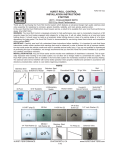
PARTS
Knob
Shifter
Boot Support
Hurst Stick
Stick Mounting Washers (2)
OEM Camaro Stick
Shifter Mounting Screws (2) Grease
Shift Knob Screw
(2014 Camaro)
Knob Nut
Stick Mounting Screws
Tie Wrap
Thread Adhesive
Technical Support (707) 544‐4761 1 www.HURST‐SHIFTERS.com TOOLS
Trim Tool
7mm, 10mm, 15mm Socket
Long Extension(s)
4mm Hex Drive
Torque Wrench
Ratchet
9/16” Wrench
Jack Stands
Phillips Screwdriver
Large Flat Blade
Screwdriver(x2)
Floor Jack
T-25 Torx Socket
7/32” Hex Wrench
Disassembly
STEP 1. Carefully unsnap the center console
trim/gauge cluster (if so equipped) cover from
center console.
TOOL: Trim Tool
Technical Support (707) 544‐4761 2 www.HURST‐SHIFTERS.com STEP 2. Place the center console trim/gauge
cluster (if so equipped) cover off to the side of the
center console.
NOTE (Camaro): The wiring to this cover may be
disconnected for better accessibility, however it is
not necessary in most cases.
NOTE (G8 GXP): Disconnect wiring connectors
for door lock, window controls, etc. Removal of
front connectors to seat warmers & traction
control is unnecessary.
STEP 3. Unscrew the shift boot ring from center
console.
TOOL: Phillips Screwdriver
2014 CAMARO TOOL: 7mm Socket, Extension,
Ratchet
STEP 4. FOR 2010-2013 CAMARO & G8 GXP:
Remove shift knob and boot assembly by sharply
pulling straight up. Also a slight twisting (side-toside) motion may aid in the removal process.
NOTE: In some instances the shift knob may be
too firmly attached. In these cases a set of large
screwdrivers can be used to carefully pry the
knob free from underneath the leather boot.
TOOL: Large Flat Blade Screwdriver
STEP 4 (CONTINUED). FOR 2014 CAMARO:
Lift collar up and rotate counter-clockwise to
detach boot from shift knob. Once the shift boot is
detached from the shift knob, lower the boot to
gain access to the torx screw on side of shift
knob. Remove torx screw. After screw has been
removed, the shift knob can be removed by lifting
straight up .
TOOL: T-25 Torx Drive
Technical Support (707) 544‐4761 3 www.HURST‐SHIFTERS.com STEP 5. Carefully raise car for under vehicle
access.
TOOLS: Floor Jack & Jack Stands
STEP 6. Evenly loosen the main rear
transmission cross member bolts (4) being careful
not to fully remove them. This should allow the
transmission and drive shaft to move down
slightly (1/2”-1”) for better access and stock shifter
removal.
TOOLS: Ratchet, Long Extension(s), & 15mm
Socket
NOTE: In some instances disassembly and
installation may be easier if the drive shaft is
disconnected, however it is not absolutely
necessary.
Refer to your vehicles service
manual.
STEP 7. Pull forward the lower dust boot at the
bottom of the shifter assembly casting just above
the driveshaft/transmission tail housing to expose
the lower shifter change rod connection.
Technical Support (707) 544‐4761 4 www.HURST‐SHIFTERS.com STEP 8. Remove the connection pin clips on both
sides of the lower shifter lever and pin connection
being careful not to damage them as they will be
re-used.
TOOL: Flat Blade Screwdriver.
STEP 9. Push out the cross pin and disconnect
the change rod from the shifter allowing it to hang
out of the way.
STEP 10. Unscrew the two (2) mounting screws
holding the mounting plate and shift lever into the
shifter assembly casting.
TOOLS: Ratchet, Long Extension and 10mm
Socket
STEP 11. Remove mounting plate and pull shift
lever firmly downward to disengage it from the
shifter assembly casting. Work the shift lever
down past the drive shaft on the driver’s side of
the vehicle and remove.
NOTE: On the V6 Camaro vehicles it will be
necessary to work the centering springs free from
the shifter from inside the vehicle either by flexing
them free from the shift lever or by removing them
entirely to allow shift lever removal.
Technical Support (707) 544‐4761 5 www.HURST‐SHIFTERS.com Assembly
STEP 12. Grease the O-rings on the aluminum
Hurst shifter pivot housing.
NOTE: DO NOT grease the main pivot Teflon®
lined spherical bearing and DO NOT grease the
lower white Teflon® bushings. All bearing
surfaces have been specifically designed for
smooth maintenance free operation without the
use of outside lubrication that will only attract dust
and dirt which will limit performance.
STEP 13. Push the Hurst Shifter up into the main
center hole of the cast aluminum shifter assembly,
aligning the mounting holes with the thread screw
holes in the bottom.
NOTE: Camaro V6- the original centering springs
can be permanently removed for use with the
Hurst Shifter or they can be repositioned and
reused on the Hurst Shifter depending on the
driver’s preference STEP 14. Place a drop of thread adhesive onto
the threads of each (2) of the counter-sunk
mounting screws.
STEP 15. Tighten the mounting screws into the
cast shifter assembly to 3.0-4.5 ft-lbs. (4-6 N-m)
to secure the Hurst Shifter.
TOOLS: Torque Wrench, Long Extension, 4mm
Hex Drive Socket Technical Support (707) 544‐4761 6 www.HURST‐SHIFTERS.com STEP 16. Ensure that the Hurst Shifter is
positioned correctly with the longer stepped side
of the lower bushings towards the driver and the
ridges of the upper stick connection holes facing
the passenger side. STEP 17. Push the change rod up to the lower
bushings in the Hurst Shifter and slide the cross
pin through the change rod and the bushings in
the Hurst Shifter to connect the linkage. STEP 18. Secure the cross pin with the locking
clips (2) on both sides of the pin and change
rod end. STEP 19. Reposition the lower dust boot onto
the shifter assembly casting. Technical Support (707) 544‐4761 7 www.HURST‐SHIFTERS.com STEP 20. Evenly re-tighten the bolts to the
transmission cross member to 43 ft.lbs. (58 N-m).
NOTE: If the driveshaft was removed, reattach and
torque connecting bolts to 85 ft-lbs. (115 N-m).
TOOLS: Torque Wrench, Long Extension, 15mm
Socket STEP 21. Carefully lower vehicle. STEP 22. From inside the vehicle push one of the
supplied boot supports onto the Hurst Shifter stub
stick. Then work the rubber boot into the groove of
the boot support.
NOTE: Make sure that the boot support and rubber
boot is pushed down far enough to allow for upper
stick attachment. STEP 23. OEM Upper Stick/Knob Attachment (only):
Place the supplied stick mounting washers onto the
threads of the stick mounting screws and attach the
Camaro OEM Stick.
NOTE: G8 GXP owners who wish to utilize the OEM
upper stick/knob option, please contact Hurst
Performance Customer Service (see last page) and
request an exchange for part number 2405065. The
supplied Camaro OEM upper stick will not fit the G8
GXP knob.
TOOL: 7/32” Hex Wrench Technical Support (707) 544‐4761 8 www.HURST‐SHIFTERS.com STEP 24. OEM Upper Stick/Knob Attachment (only):
Push the knob/boot assembly onto Camaro OEM
Upper Stick, making sure it securely snaps into place
and does not twist on the shaft.
FOR 2014 CAMARO: Secure shift knob to stick with
Shift Knob Screw (included).
2014 CAMARO TOOL: 4mm Allen Drive
STEP 25. Hurst Chrome Upper Stick/White Knob
Attachment (only):
Push the supplied boot support onto the chrome
Hurst stick just below the “Hurst” lettering. STEP 26. Hurst Chrome Upper Stick/White Knob
Attachment (only):
Place the supplied stick mounting washers onto the
threads of the stick mounting screws and attach the
Hurst Stick ensuring the ridges of upper and lower
sticks mesh properly.
TOOL: 7/32” Hex Wrench STEP 27. Hurst Chrome Upper Stick/White Knob
Attachment (only):
Trim the tie wrap that holds the original leather shift
boot to the boot ring(Camaro) or knob (G8 GXP)
and remove leather boot.
TOOL: Cutting Pliers Technical Support (707) 544‐4761 9 www.HURST‐SHIFTERS.com STEP 28. Hurst Chrome Upper Stick/White Knob
Attachment (only):
Turn the leather boot inside-out and attach it to the
boot support on the Hurst Stick with the supplied
tie wrap. Trim away the excess “tail” of the tie wrap
as necessary.
TOOL: Cutting Pliers STEP 29. Screw in the leather shift boot ring into
the center console.
TOOL: Phillips Screwdriver
2014 CAMARO TOOL: 7mm Socket, Extension,
Ratchet
STEP 30. Reconnect any of the center console
connections that may have been disconnected
from the center console trim piece. STEP 31. Reinstall the center console trim piece
by carefully snapping into place. Technical Support (707) 544‐4761 10 www.HURST‐SHIFTERS.com STEP 32. Hurst Chrome Upper Stick/White Knob
Attachment (only):
Install the supplied jam nut all the way down onto
the threads of the Hurst Stick. Then screw on the
Hurst Knob aligning the gear pattern. While holding
the knob in position tighten the jam nut against the
knob to hold in position.
TOOL: 9/16” Wrench STEP 33. Before operating the vehicle, test the
shifter through all gears making sure that each gear
including reverse and be engaged fully and
smoothly without rough movement or binding. Also,
ensure that the shifter fully and smoothly selfcenters in the neutral position and does not hang in
the reverse, 1st-2nd gear, or 5th-6th gear plane.
Correct any problems before operating the vehicle. NOTE:
We have encountered concerns from customers regarding an increase in audible noise as a result of
operating harmonics and vibration that is directly transmitted through the shift linkage following the
installation of the shifter. The following components can be installed to reduce this noise/vibration,
however, are not intended to mask internal problems of the transmission, clutch (and related clutch
components), or engine components that may have been modified. Each individual vehicle is different
any may have different harmonics that change with varying vehicle, driving, wear, and atmospheric
conditions. Thus, the suggestions that follow may work better in some vehicles than others and may
not completely eliminate vibration noise to certain customers’ satisfaction. A fair amount of
experimentation and testing may be required to reduce audible vibration noise to acceptable levels.
Technical Support (707) 544‐4761 11 www.HURST‐SHIFTERS.com DYNAMAT APPLICATION
NOTE: Apply even pressure over the entire back (foil) surfaces of the Dynamat® during installation to
ensure complete and proper adhesion.
Trim Dyamat® to Size.
Note: Various effective application locations -
change rod / transmission rail connection
change rod / lower shifter connection
change rod / transmission rail connection
lower stick / upper handle connection
Technical Support (707) 544‐4761 12 www.HURST‐SHIFTERS.com NEOPRENE ISOLATOR APPLICATION:
NOTE: This step should only be implemented if the
above Dynamat® application is insufficient to
eliminate noise. Do not install this if your vehicle will
be used in any form of racing and/or competitive
driving, as overall strength and durability as well as
shift quality and feel may be diminished with the use of
this kit.
Separate the upper and lower Hurst Shifter stick levers
by unscrewing the connecting bolts and then position
the supplied neoprene isolators (2) between the upper
and lower stick halves and retighten. Ensure the bolts
will not come loose during repeated hard driving.
Periodic inspection and verification may be necessary.
IMPORTANT: RETAIN THESE INSTRUCTIONS FOR FUTURE REFERENCE
Technical Service
A highly trained technical service department is maintained by Hurst Performance to answer your
technical questions, provide additional product information and offer various recommendations.
Technical service calls, correspondence, and warranty questions should be directed to:
Hurst Performance Products
(707) 544-4761
www.Hurst-Shifters.com
Technical Support (707) 544‐4761 13 www.HURST‐SHIFTERS.com