1
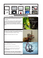
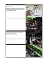
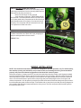
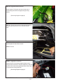
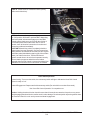
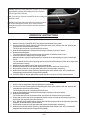
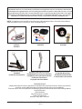
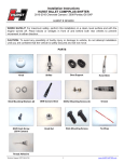
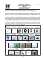
FORM 159 1522
HURST ROLL CONTROL
INSTALLATION INSTRUCTIONS
# 5671520
2011+ CHALLENGER SRT8
©2012 by Hurst Performance
Thank you for purchasing the Hurst Roll Control system which features an advanced design high quality stainless steel
valve assembly for resistance to corrosion, greater durability, reliability, and more precise positive action.
In the event that this Hurst Roll/Control should require service, a rebuilt kit is available from your local Hurst performance
dealer (Part #5671500)
WARNING: The Hurst Roll Control is designed primarily for high performance race cars to momentarily (maximum of 60
seconds) keep the front brakes engaged while staging for a drag race. It will not safely function as a long term brake
holding device. It should never be used as a temporary brake holding device in place of a parking brake or of a driver
depressing the brake pedal. The Hurst Roll Control is recommended for use during closed track events and competitive
driving venues ONLY!
IMPORTANT: Carefully read and fully understand these instructions before installing. It is important to note that these
instructions contain certain cautions and warnings that must be observed in order to reduce the risk of improper installation that could render the vehicle unsafe and result in possible serious bodily injury. If you are not qualified or experienced
at performing this type of installation, we strongly recommend that you have the Hurst Roll Control installed by a qualified
and certified automotive mechanic.
INSTALLATION NOTES: Any job will be easier and the results more satisfactory if cleanliness is observed. This is especially important when working on the brake system. Do not allow dirt or foreign matter to contaminate the system. This
Hurst Roll Control solenoid valve is installed in the front brake system for momentary (maximum of 60 seconds) holding.
The solenoid valve will not interfere with normal brake operation when properly installed and operated in accordance with
directions provided.Allow vehicle to cool before beginning installation.
PARTS
Stainless Steel
Stainless Steel
Stainless Steel
Adapter (2)
Brakeline- to HCU Brakeline-to Master
4A Fuse
5/16” Eyelet(3)
1/8 NPT plug (2)
1/4” Flat Washer (2)
HURST PERFORMANCE
Lit Momentary
Switch
M8 Nut
M8 Bolt /
M8 Washer (2)
Convoluted Cover
18 ga. Wire
Butt
Connectors (3)
Rocker Switch
Female(4)/
Male (2) Terminal
Scotchlok™
Conctr. (2)
1/4-20 Nut (2)
Stainless Steel
Bracket
CHATSWORTH, CA
1/10
1/4-20 Soc
Screw (2)
Tie Wrap (2)
1/4” Lock Washer (2)
Solenoid Valve
www.HURST-SHIFTERS.com
7/16”,15mm(short),
16mm(short), 13mm,
11mm Wrench
TOOLS
Ratchet / Extension
Pliers
7/16” , 9/16”, 13mm Socket
Electrical Tape
Clean Rags
Teflon® Tape
Loctite®
Wire Stripper/Crimper
Plastic Trim Tool
BRAKE LINE INSTALLATION
NOTE: ARROW SIGN (
) INDICATES LOCATION OF FRONT OF VEHICLE WITH RESPECT TO THE PICTURE VIEW.
STEP 1. Identify the mounting location of solenoid and the
Master Cylinder (M.C) front brake line within the engine
compartment.
Mounting Location
Master Cylinder
Front Brake Line
Important! This kit will only work for SRT8 models.R/T
models can only partially turn off Traction Control
(ESP). Unless the car was modified to completely
remove Traction Control, R/T models should not install
this kit.
Hydraulic Control
Unit (HCU)
Fuse Box
STEP 2. Attach mounting bracket to solenoid as shown.
Add a few drops of Loctite® (red) to bolt threads. Place one
1/4-20 bolt, 1/4” flat washer, 1/4” lockwasher, and 1/4-20 nut
on each hole and fully tighten to 20Nm (15 ft-lbs).
TOOLS: 7/16” wrench, ratchet, 7/16” socket
STEP 3. Tighten the provided adapters and plugs to
solenoid as shown.
TOOLS: 16mm Wrench, 11mm Wrench
To Master Cylinder
Front Brake Line
NOTE: Use Teflon® tape to ensure a leak-proof seal.
Solenoid Nut
To HCU
Plugged
CAUTION: Using an excessive amount of thread sealer
can contaminate the solenoid valve or brake system.
Use tape sparingly.
If solenoid body loosens while tightening adapters/
plugs. First, make sure ports are correctly aligned and
then use a 9/16”socket to re-tighten top solenoid nut.
HURST PERFORMANCE
CHATSWORTH, CA
2/10
www.HURST-SHIFTERS.com
STEP 4. Ensure that the new brake line routing is understood prior to installation. However, DO NOT attach lines to
solenoid at this time.
NOTE: Using Teflon® tape on flare fitting threads is generally not recommended.However, if used do not cover any
portion of line opening with tape.
To Hydraulic
Control Unit (HCU)
Hurst
Solenoid
To Master Cylinder
Front Brake Line
STEP 5. Locate fuse box in engine compartment. Open
fuse box lid and unclip fuse box front guard.
Fuse Box Front
Guard
STEP 6. Place clean rags under and around HCU in order
to keep fluid from spilling on vehicle. Unscrew Master
Cylinder front brake line from HCU.
Master Cylinder
Front Brake Line
TOOLS: 15mm Wrench, Clean Rags
NOTE: Avoid spilling brake fluid, especially on painted and/
or plastic surfaces. Remove any and all excess brake fluid
immediately with a clean rag.
Hydraulic Control
Unit (HCU)
STEP 7. Unclip the brake line clip closest to the HCU
Brake Line Clip
HURST PERFORMANCE
CHATSWORTH, CA
3/10
www.HURST-SHIFTERS.com
STEP 8. Unclip Master Cylinder front brake line from brake
line clip assembly(middle brake line).
Reclip brake line clip excluding Master Cylinder front brake
line from the clip assembly.
Front Brake Line
STEP 9. Recommended Installation Method: Thread the
appropriate fitting of the Hurst Roll Control brake line into the
M.C front brake line. Thread the other end of the Hurst Roll
Control brake line into the solenoid adapter. However, do not
completely tighten fitting at this time to allow for minor
adjustments. (Slight adjustment (bending/flexing) of lines may
be required for proper alignment).
New Line
To MC Front
Brake Line
TOOLS: 15mm Wrench (Brake Line nut) - Short
16mm Wrench (Adapter) - Short
NOTE: Place clean rag under area where solenoid will be
mounted, so bottom of solenoid does not scratch car body.
STEP 10. Recommended Installation Method: Thread
the appropriate fitting of the Hurst Roll Control brake line
into the solenoid adapter. Thread the other end of the Hurst
Roll Control brake line into HCU. However, do not completely tighten fitting at this time to allow for minor adjustments. (Slight adjustment (bending/flexing) of lines may be
required for proper alignment).
New Line
To HCU
TOOLS: 15mm Wrench (Brake Line nut) - Short
16mm Wrench (Adapter) - Short
NOTE: Place clean rag under area where solenoid will be
mounted, so bottom of solenoid does not scratch car body.
STEP 11. Install Hurst Roll Control mounting bracket.
Add a few drops of Loctite (red) to bolt threads.Place first
M8 washer on mounting bracket face and second M8
washer on back face of mounting location.Fully tighten M8
bolt / nut to 20Nm (15 ft.-lbs). Once lines are aligned,
tighten all flare fittings. DO NOT OVER TIGHTEN AS THIS
WILL CAUSE LEAKS.
TOOL: 13mm Wrench, ratchet,13mm socket.
HURST PERFORMANCE
CHATSWORTH, CA
4/10
www.HURST-SHIFTERS.com
STEP 12. BEFORE OPERATING VEHICLE:
Bleed ALL (back,then front on both sides) brakes
by following manufacturer’s service manual guidelines (front
brakes will usually have the most air).
Make sure all fittings are fully secured.
Verify no leaks are present, THERE SHOULD BE
NO LEAKAGE. The brake pedal should be firm with a solid
feel. If brake pedal slowly compresses to the floor,there is a
Installed Hurst
brake fluid leak and/or air in system. Check and re-bleed if
Roll Control
necessary. Do not operate vehicle if leaks and/or air in the
lines is present no matter how minor.
STEP 13. Use provided (2) tie wraps to hold Master
Cylinder front brake line to brake line clip by wrapping tie
wrap around clipped brake lines as shown.
Add Tie
Wrap
TOOLS: Pliers
MC Coupler
WIRING INSTALLATION
NOTE: The Hurst Roll Control Solenoid Valve is designed for 12V DC operation only. For added safety,
two switches (arming and activation) are provided in this kit. Following the wiring recommendation
properly will prevent accidental engagement of the Hurst Roll Control system.
Disconnect negative (-) battery terminal. If more wire is needed then what is provided, use #18 gauge standard
insulated automotive wire to assure good electrical connection and conductivity. Wiring should be as neat and
direct as possible. DO NOT connect wiring in such a fashion as to apply added stress or excessive stretch to
wires. Use convoluted sleeve to protect wires, keep wiring away from sharp edges/corners, hot engine, and
exhaust components. Join all splices by using the provided connectors/terminals and wrap each splice/connection with a adequate grade of electrical tape. A fuse holder with a 4-amp fuse is provided (See wiring diagram for
wiring details) and should be incorporated into the wiring circuit. The fuse can protect the electrical system in
the event of a short circuit.
HURST PERFORMANCE
CHATSWORTH, CA
5/10
www.HURST-SHIFTERS.com
STEP 14. Suggested Solenoid Ground:
Ground
Ground: Attach 5/16”eyelet connector to black wire of
solenoid and ground wire to an appropriate grounding
location.
(See wiring diagram on page 9)
STEP 15. Switch wiring can be run through the firewall by
going through the grommet for the hood latch release
cable.
STEP 16. Carefully unsnap the center console trim/
cupholder plate from the center console.
TOOLS: Trim Tool
STEP 17. Suggested 12V Source:
Disconnect the 12V accessory/cigarette lighter socket
wiring harness connection. Using the supplied (2) 18ga. tap
connector and connect the appropriate switch wires to the
12V power source and ground wire.
(See wiring diagram on page 9)
HURST PERFORMANCE
CHATSWORTH, CA
6/10
www.HURST-SHIFTERS.com
STEP 18. Mount switches in desired location (usually
within reach of the driver).
Momentary Engagement
Switch
On/Off Arming Switch
STEP 19. Reconnect battery and turn ignition switch to
the “ON” position. While still in park and NOT depressing
your brake pedal, activate and engage your Hurst Roll/
Control system (make sure you can hear the clicking of
the solenoid) several times and check fuse. If fuse is
burned, check all electrical connections for a short and
correct any problems immediately.
CAUTION: Before driving vehicle, completely check the
brake system for proper operation. Check all connections
under pressure for leaks and be sure that you have a good
solid brake pedal (bleed brakes again to get a firmer brake
pedal). On a flat level surface, Test the Roll Control
system several times to be sure that it operates correctly.
Be sure that the proper two wheels have the brakes
engaged when the Roll Control is actuated and that all four
wheels are free when the Roll Control switch is released.
Momentary
Engagement
Switch
On/Off
Arming
Switch
Basic Switch Operation
System Arming: Turn on rocker switch, the momentary switch will light to indicate the Hurst Roll Control
system is ready or “hot”.
Solenoid Engagement: Depress and hold momentary switch (Do not hold for more than 60 seconds).
See “Hurst Roll Control Operation” for competiton use
Caution: Holding the solenoid valve closed for more than 60 seconds can cause the fuse to burn-out, permanently damaging the solenoid valve, and/or result in other damage. De-activate (switch off) arming switch when
the Hurst Roll Control is not in use to prevent accidental engagement.
HURST PERFORMANCE
CHATSWORTH, CA
7/10
www.HURST-SHIFTERS.com
STEP 20. Before executing a burnout, turn OFF your Traction
Control/ESP by pressing and holding the “ESP off” button.
“ESP Off“ lights will illuminate.
Traction Control/ ESP
Note: Turn ON your Traction Control/ESP when not using the
Hurst Roll Control.
Warning: Performing a burnout without the Traction Control/
ESP off can damage the vehicle. Also, avoid excessive
loading/shocking of the clutch,flywheel, and other drivetrain
components.
OPERATION INSTRUCTIONS
To actuate the Hurst Roll/Control system (BURNOUT):
1. With the Traction Control/ESP OFF, fully depress and hold the brake pedal.
2. Arm the Hurst Roll Control system by depressing the rocker (arm) switch to the “ON” position (the
engage button switch should illuminate).
The next steps should be complete within 60 seconds.
3. Hold the illuminated button switch down and keep it held down until step 7 below.
4. Release the brake pedal.
The front brakes will now be locked and the rear wheels un-locked and free to spin.
5. Automatic Vehicles- sharply step on the gas pedal.
Manual Vehicles- raise the engine speed to a moderate level and smoothly but quickly release the
clutch.
The rear wheels should now be spinning and the vehicle should be stationary if the above steps have
been performed correctly.
6. Modulate the gas pedal to control the amount of wheel spin.
7. Release the illuminated button switch and allow the vehicle to “drive-out” of the burnout.
8. Be prepared to ease off on the gas pedal and press the brake pedal if necessary.
9. Disarm the Hurst Roll Control system by depressing the rocker switch to the “OFF” position (the
engage button switch should no longer be illuminated).
10. Press the “ESP off” button again and/or restart vehicle to turn on your Tractic Control system.
To actuate the Hurst Roll/Control system (LAUNCH CONTROL – Automatic Vehicles Only):
1. With the vehicle staged fully, depress and hold the brake pedal.
2. Arm the Hurst Roll Control system by depressing the rocker (arm) switch to the “ON” position (the
engage button switch should illuminate).
The next steps should be complete within 60 seconds.
3. Hold the illuminated button switch down and keep it held down until step 6 below.
4. Release the brake pedal.
The front brakes will now be locked and the rear wheels un-locked and free to be loaded.
5. Slowly and smoothly step on the gas pedal to load the torque converter and drivetrain just prior to
wheel spin (this step may take some practice).
6. GO! - Release the illuminated button switch and modulate the gas pedal as the light turns green/flag
drops/etc. to hard launch the vehicle forward.
7. Be prepared to ease off on the gas pedal and press the brake pedal if necessary.
8. Disarm the Hurst Roll Control system by depressing the rocker switch to the “OFF” position (the
engage button switch should no longer be illuminated).
HURST PERFORMANCE
CHATSWORTH, CA
8/10
www.HURST-SHIFTERS.com
ENJOY!
Wiring Diagram
Schematic Circuit Diagram
HURST PERFORMANCE
CHATSWORTH, CA
9/10
www.HURST-SHIFTERS.com
-- 90 Day Limited Warranty -Hurst Roll Controls are covered for 90 days from the date of retail purchase to be free from defects in material and
workmanship to the original purchaser (not warranted against normal wear, misuse or abuse).This warranty covers the
original purchasing consumer. This warranty is limited to repair or replacement by Hurst performance of any Hurst
Performance Product that fails because of a defect in materials or workmanship. Implied warranty: Any warranties
implied by law are limited to the duration of this warranty, (except in those states where prohibited by law).
NOTE: Complement your Hurst Roll Control with some of the following products. Check the Hurst website at
www.hurst-shifters.com for various stick, knob, and handle options:
Universal Hurst T-Handle
w/ Button
# 1530011
Billet/Plus 2 Shifter
# 3916020
For Manual Transmission
Hurst Switch Kit
# 2483876
HardDrive Stick
# 5388651 (Black Delrin Handle)
# 5388660 (Brushed Aluminum Handle)
# 5388650 (Titanium Anodized handle)
For Manual Tranmission
Equipped with Hurst Shifter
Sidewinder Shift Knob
# 1630069
Comp Stick Kit
# 5380402 (Black Plate)
# 5380403 (Polished Plate)
For Automatic Transmission
Technical Service
A highly trained technical service department is maintained by Hurst Performance to answer your technical
questions, provide additional product information and offer various recommendations.
Technical service calls, correspondence, and warranty questions should be directed to the following address:
Hurst Performance
1500 Overland Ct
West Sacramento, CA 95691
Phone (707) 544-4761
Monday-Friday 7AM to 4PM PST
HURST PERFORMANCE
CHATSWORTH, CA
10/10
www.HURST-SHIFTERS.com