1
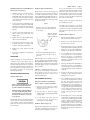
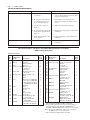
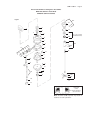
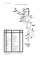
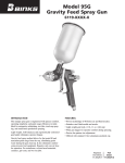
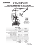
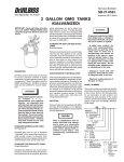
SERVICE Bulletin SBBI-19-087-F Replaces SBBI-19-087-E AIR MOTOR DRIVES Important: Read and follow all instructions and SAFETY PRECAUTIONS before using this equipment. Retain for future reference. QS-5003 air motor drive, 15-1 gear reduced for paint drums having built-in agitators. Includes air adjusting valve for 1/4" NPT(M) inlet. High pressure can cause serious injury. Pressure is maintained in a pressure tank after the system has been shutdown. Before attempting removal of fill plug or cover, relieve tank pressure. Pressure Relief Procedure 1.Turn off the main air supply to the tank. 2. Close air inlet valve located on tank air manifold. 3. Bleed off air in the tank by turning the air inlet valve handle counterclockwise. Wait until all the air has escaped through the valve before removing the pressure tank cover or fill plug. DESCRIPTION The air motors covered in this service bulletin are designed to drive paint agitators when connected to a source of clean, dry, air pressure. QS-5012 air motor drive, 15-1 gear reduced for pressure tank agitator. Includes air adjusting valve with necessary hose and fittings for hookup to tank regulator. QMS-430 direct drive air motor and agitator assembly for 2.8 gal. stainless pressure tanks. Includes removable agitator and air motor with air shut off valve and necessary hose and fittings for hookup to tank regulator. Agitator supplied is suitable for use with halogenated hydrocarbon based solvents. QMG-416 direct drive air motor and agitator assembly for 2.8 gal. galvanized pressure tanks. Includes removable agitator and air motor with air shut off valve and necessary hose and fittings for hookup to tank regulator. Agitator supplied is not suitable for use with halogenated hydrocarbon based solvents. 4.Leave the air relief valve open until you have reinstalled the cover or fill plug. INSTALLATION QS-5012 Installation onto Pressure Tank with Agitator (Refer to Figure 3.) 1. Position agitator assembly over bearing assembly in lid until support (60) is fully seated on bearing assembly. It may be necessary to rotate the drive assembly in order to get the agitator assembly to engage in the gear box. Once engaged, again rotate the drive assembly until the air motor inlet and exhaust ports are aimed toward the rear of the tank. This will allow proper hookup of air hose and fittings to the tank regulator. 2.Tighen hex head cap screw (61). 3. Remove main air supply inlet valve from tank regulator and install service tee (67) in open port. 4. Connect tank air supply inlet valve to open end port of service tee (67). Install nipple (64) in open port of service tee. 5. If not already connected, install elbow (63) in air motor inlet port and upper nipple (64) in open elbow port. Connect air adjusting valve (65) to upper nipple. Connect hose assembly (66) between lower nipple (64) and air adjusting valve. QMS-430 and QMG-416 Installation Into Pressure Tank (Refer to Figure 1. 1. Follow pressure relief procedure before removing or loosening any tank lid components. 2. If not already separated, loosen propeller set screw (32) and remove propeller from shaft. 3. Remove seal plug from paint tank lid and clean sealing surface around threaded port. 4. Make sure that the o-ring (26) is fully seated in groove of adapter (24). Install and tighten air motor adapter and shaft assembly into threaded center hole in tank lid. 5.Loosen set screws (25) in adapter. Rotate air motor assembly until inlet port is aimed toward the rear of the tank to allow hookup of air hose and fittings to supply air inlet of tank regulator or service tee. Air hose provided for hookup is 10" long. 6. Retighten both set screws (25). 7. Install propeller (31) on end of agitator shaft (30). Secure propeller with set screw (32). 8. Remove main air supply inlet valve from tank regulator and install service tee (23). Install lower nipple (20) in open port of service tee. 9. Connect tank air supply inlet valve to end port of service tee (23). Install lower nipple (20) in open port of service tee. 10.If not already connected, install elbow (19) in air motor inlet port. Install upper nipple (20) in open port of elbow. Connect air adjusting valve (21) to upper nipple. Then, connect hose assembly (22) between air adjusting valve and lower nipple. (Continued on Page 3) Page 2 SBBI-19-087-F SAFETY PRECAUTIONS This manual contains important information that all users should know and understand before using the equipment. This information relates to USER SAFETY and PREVENTING EQUIPMENT PROBLEMS. To help you recognize this information, we use the following terms to draw your attention to certain equipment labels and portions of this Service Bulletin. Please pay special attention to any label or information that is highlighted by one of these terms: Note Important information that tells how to prevent damage to equipment, or how to avoid a situation that might cause minor injury. Important information to alert you to a situation that might cause serious injury if instructions are not followed. Information that you should pay special attention to. The following hazards may occur during the normal use of this equipment. Please read the following chart. HAZARD CAUSE SAFEGUARDS Fire Solvents and coatings can be highly 1. flammable or combustible, especially when sprayed. 2. 3. Adequate exhaust must be provided to keep the air free of accumulations of flammable vapors. Smoking must never be allowed in the spray area. Fire extinguishing equipment must be present in the spray area. Explosion Hazard Making changes to pressure tank 1.Never drill into, weld, or modify tank in any way. Tank Rupture will weaken it. Carefully follow all instructions for motor drive installation. 2. Do not adjust, remove, or tamper with the safety valve. If replacement is necessary, use the same type and rating of valve. Explosion Hazard- Halogenated hydrocarbon solvents - - Trichloroethane are not chemically compatible with the aluminum that might be used in many system components. The chemical reaction caused by these solvents reacting with aluminum can become violent and lead to an equipment explosion. CA PROP 65 Aluminum is widely used in spray application equipment - such as material pumps, cups, regulators, valves, etc. Check all equipment items before use and make sure they can be used safely with these solvents. Read the label or data sheet for the material you intend to spray. If in doubt as to whether or not a coating or cleaning material is compatible, contact your material supplier. Any other type of solvent may be issued with aluminum equipment. PROP 65 WARNING WARNING: This product contains chemicals known to the State of California to cause cancer and birth defects or other reproductive harm. IT IS THE RESPONSIBILITY OF THE EMPLOYER TO PROVIDE THIS INFORMATION TO THE OPERATOR OF THE EQUIPMENT. FOR FURTHER SAFETY INFORMATION REGARDING BINKS AND DEVILBISS EQUIPMENT, SEE THE GENERAL EQUIPMENT SAFETY BOOKLET (77-5300). SBBI-19-087-F QS-5003 Installation onto Drum Mounted Agitator (Refer to Figure 2) 1. Adapter (47) has two thread sizes: 1-1/2" NPS (M) on one end and 2" NPS (M) on the other end. Choose the proper thread size and place adapter over agitator shaft of drum and screw down securely. 2. Select proper driver shaft (46) and attach it to drive coupling assembly (48) with driver pin (45) and cotter pins (44). Place this assembly on shaft of drum agitator. Air Motor Gear Box Lubrication Every 2 Days - Remove oil fill plug and check oil level. Proper oil level is indicated on outside of gear box housing. If oil level is low, add 140-weight SAE Gear Oil or a high quality worm gear lubricant. Replace pipe plug and tighten to 20 foot-pounds (27 N-m) of torque. Page 3 Do not pry front plate (77) or end plate (71) from air motor body (76) with a screw driver; this will dent the surface of the body and plates causing leaks. A puller tool should be used to remove the plate from the motor body while maintaining the position of the shaft. Always install new gaskets (73) when reassembling air motor. Note Gear box oil is most easily drained just after motor operation, while oil is still warm. 3. Slip air motor support (39) down over drive coupling assembly (48) and adapter (47). Approx. 1/8" Gap (top of oil level to bottom of fill hole) Assemble the end plates to the body using an arbor press with a pusher acting on both races of the bearing while rigidly supporting the opposite (drive) end of the shaft. Gear Box (Refer fo Figure 5) 4.Tighten air motor support (39) securely with screw assembly (43). 1. Remove oil fill plug (88) or cover plate (84) and drain gear box lubricant. 5. Install gear box (38) on air motor support (39), being sure to engage shaft of drive coupling assembly (48). 2. Remove set screws (91) and remove gear box from air motor. 6.Tighten cap screw and hex nut (40 and 42). 7. Connect air supply line to air adjusting valve (52). OPERATION Before operating air motor, lubricate as covered in next section. Open valve to main air line; then slowly open air adjusting valve until agitator turns. To extend air motor life, adjust air pressure setting to run motor at about one revolution per second. The agitator should be run continuously while using the tank. PREVENTIVE MAINTENANCE Air Motor Lubrication Note Do not overfill. Overfilling may cause oil to leak out of vent cap on top of gear box. After first 250 hours of operation, remove gear box and drain gear oil. Refill gear box with 140-Weight SAE Gear Oil or a high quality worm gear lubricant. Replace pipe plug and tighten to 20 foot-pounds (27 N-m) of torque. 6 Months or 2500 Operating Hours - Replace gear oil according to instructions above. Replace gear oil more often if environment causes oil to become contaminated during use. REPLACEMENT OF PARTS Failure to properly lubricate the air motor will result in premature motor failure and will void warranty. Lubricate air motor daily by adding 4 or 5 drops of SAE 10 weight oil into air inlet fitting. For convenience, an automatic oiler may be connected to the air inlet. Periodically - Remove air adjusting valve and air strainer and flush motor with a clean suitable solvent. Remove trapped particles from screen in air inlet and clean air strainer felt. Removal of Air Motor and Gear Box (Refer to Figure 3 - typical assembly.) 1. Follow pressure relief procedure (Ref. Pg. 1) before removing or loosening any components. 2.Turn off valve to main air supply and disconnect air adjusting valve (65) at nipple (64). 3.Loosen upper cap screw (61) and remove air motor and gear box assembly from support (60). Air Motor (Refer to Figure 4) Holes must be drilled for new dowel pins (72) after assembling front plate (77) on new body (76) for alignment of parts. 3. Disassembly gear box per exploded view, Figure 5. Discard gaskets (87 and 92). Do not remove oil seal (90) unless leakage or seal damage is indicated. 4. If oil seal (90) was removed, inspect seal seating bore in housing (89). Remove any burrs or contaminants from seal seating bore. Burrs or contaminants could distort new oil seal during installation. 5. Inspect gear and shaft assembly (86) for wear grooves, burrs, or contamination of seal seating area. If seal seating area is damaged, shaft must be repaired or replaced. 6. Inspect all other parts for wear spots, chipping, or other damage. Replace damaged or worn parts. 7. If oil seal (90) is being replaced, inspect new seal for damage before installing. Use arbor press to install seal. Press fixture diameter must be close fit with gear box bore diameter to avoid damage to seal. Install with inner casing and sealing lip toward bottom of bore. Drive seal squarely into bore to avoid warping. Check that seal is fully seated all around at bottom of bore. 8. Reassemble gear box per exploded view. Install new gaskets (87 and 92). Just prior to assembling gear box with air motor, apply a small dab of thread locking compound (81) to threads of setscrews (91). Connect motor and gear box and torque set screws (91) to 60 inch-pounds (6.8 N-m), minimum. Refill gear box per gear box lubrication instructions. Page 4 SBBI-19-087-F AIR MOTOR DRIVE SERVICE CHECKS CONDITION CAUSE CORRECTION A. Air motor sluggish or inefficient. 1. Air motor needs lubrication 1.Lubricate (see "Air Motor Lubrication" or cleaning. section). Disassemble and clean per parts replacement instructions. 2. Motor vanes need replacing 2. Disassemble, clean motor per parts or contaminants present in replacement instructions. Replace worn motor chamber, Figure 4. vanes. 3.Low oil level in gear box, Figure 5. 3. Add oil per lubrication instructions. 4. Gear and shaft assembly (86) 4. Replace worn parts per parts replacement and/or worm gear (93) worn, instructions. Figure 5. 5. Air motor bearing (68 or 79) 5. Replace bearings per parts replacement worn, Figure 4. instructions. B. Oil leakage from gear box. 1. Seal (90, Figure 5) worn. 1. Replace seal per parts replacement instructions. Direct Drive Air Motor and Agitator Assemblies QMS-430 (Stainless Steel Shaft) QMG-416 (Plain Steel Shaft) Parts List for Figure 1 Ref. Replacement No. Part No. Description 1 QN-97 Carrying Handle 2 QMG-18 End Cap •†3 --- End Cap Gasket †4 PT-58 Bearing †5 Purchase Locally Machine Screw 1/4-28 x 1/2 †6 --- Front Plate •†7 PT-59-1-K10 End Plate Spacer Kit (Kit of 10) †8 QS-189-1-K10 Dowel Pin (Kit of 10) †9 --- Body •10 --- Vane †11 PT-57 Rotor Assy. for QMG-416 --- Rotor Assy. for QMS-430 (Not available separately, order QMS-428 Air Motor †12 --- End Plate †13 PT-56 Seal 14 --- Strainer Cup 15 --- Screen •16 --- Felt 17 --- Strainer Body †18 350-401 Air Strainer *19 Purchase Locally Street Elbow 1/4" (M) x 1/4" (F) NPT 20 H-2008Nipple 1/4" NPS (M) 1/4" NPT (M) 21 HAV-500 Air Adjusting Valve, 1/4" NPS (M) x 1/4" NPS (F) Ind. Parts Req'd. 1 1 1 2 12 1 2 4 1 4 1 1 1 1 1 2 1 1 1 1 2 Ref. Replacement No. Part No. Description 22 HA-57011 23 Purchase Locally #24 --- #25 --- 26 SSG-8184-K2 27 KK-5041 27A --- 27B --- #28 --- #29 Purchase Locally 30 QMS-73 QMG-56 31 QMS-448 31A --- 32 Purchase Locally 32A KK-4991 KK-4990 Hose Assembly Service Tee 1/4" Galv. Adapter Set Screw (1/4-20 x 1/4") O-Ring (Kit of 2) Shaft Seal Kit Shaft Seal Retainer Shaft Coupling Set Screw (1/4-20 x 1/4" s.s.) Agitator Shaft for QMS-430 Agitator Shaft for QMG-416 Propeller Kit (includes 31A and 32 Agitator Propeller Set Screw (1/4-20 x 3/8" s.s.) Agitator Kit for QMS-430 (Includes Item Nos. 24, 25, 28, 29) Agitator Kit for QMG-416 (Includes Item Nos. 24, 25, 28, 29) Ind. Parts Req'd. 1 1 1 2 1 1 1 1 1 2 1 1 1 1 1 1 1 1 • Parts included in KK-5001-1 Air Motor Repair Kit. # When replacing either Ref. Nos. 24, 25 or 28 and 29, you must order Ref. No. 32A, KK-4991 for QMS Models or KK-4990 for QMG Models. The kit includes necessary parts. Ref. No. (15) 2 ea. and Ref. No. (16) 4 ea. are included in KK-5006 Strainer Screen and Felt Kit. † Parts included in PT-410 Air Motor Assembly. SBBI-19-087-F Page 5 Direct Drive Air Motor and Agitator Assemblies QMS-430 (Stainless Steel Shaft) QMG-416 (Plain Steel Shaft) Figure 1 32A 24 2 1 26 3 4 27A 5 7 28 32A 8 15 16 15 17 27 (See Detail and Note below) 27B 6 18 25 29 9 10 14 30 11 19 7 20 21 8 12 22 4 5 13 31A 32 20 31 23 Shaft Seal (27A) Detail drawing (faces down) Note: Retainer (27B) required only if tank is used for vacuum operation. Page 6 SBBI-19-087-F Figure 2 QS-5003 Gear Drive Air Motor 34 35 36 52 51 33 35 37 50 38 Oil Fill 49 39 42 41 40 43 Parts List for Figure 2 Ref. Replacement No. Part No. Description 33 350-401 Air Strainer 34 --- Strainer Cap +35 --- Screen •+36 --- Felt 37 --- Strainer Body 38 --- Gear Box (Figure 5) 39 QS-238 Air Motor Support 40 Purchase Locally Hex Head Cap Screw 3/8-16 x 2-1/2" 41 Purchase LocallyLock Washer 3/8" 42 Purchase Locally Hex Nut, 3/8-16 43 QS-456 Screw Assembly 44 Purchase Locally Cotter Pin 1/16" x 1/2" 45 QS-237 Driver Pin 46 QS-240 1/2" Driver Shaft QS-242 7/16" Driver Shaft 47 QS-457 Adapter 48 QS-455 Drive Coupling Assembly 49 --- Air Motor, Figure 4) 50 Purchase Locally Street Elbow, 1/4" (M) x 1/4" (F) NPT Galvanized 51 H-2008Nipple, 1/4" NPS (M) x 1/4" NPT (M) 52 HAV-500 Air Adjusting Valve 1/4" NPS (M) x 1/4" NPS (F) Ind. Parts Req'd. 1 1 2 1 1 44 48 1 1 1 1 1 2 1 1 1 1 1 1 1 •Included in KK-5001-1 Air Motor Repair Kit. See page 8 for additional parts included in kit. +Ref. No. (35) 2 ea. and Ref. No. (36) 4 ea. included in KK-5006 Strainer Screen and Felt Kit. 46 47 45 SBBI-19-087-F Page 7 Figure 3 QS-5012 Gear Drive Air Motor 54 53 55 56 55 57 58 Oil Fill Plug 63 59 64 60 62 65 61 61 66 64 67 Parts List for Figure 3 Ref. Replacement No. Part No. Description 53 350-401 Air Strainer 54 --- Strainer Cap +55 --- Screen •+56 --- Felt 57 --- Strainer Body 58 --- Gear Box (Figure 5) 59 32243-133 Washer 60 QMS-35 Air Motor Support 61 Purchase Locally Hex Head Cap Screw 3/8-16 x 2" 62 --- Air Motor (Figure 4) 63 Purchase Locally Street Elbow 1/4" (M) 1/4" NPT (F) 64 H-2008Nipple 1/4" NPS (M) 1/4" NPT (M) 65 HAV-500 Air Adjusting Valve 1/4" NPS (F) x 1/4" NPS (M) 66 HA-57011 Hose Assembly 67 Purchase Locally Service Tee 1/4" Galv. Ind. Parts Req'd. 1 1 2 1 1 1 1 2 1 1 1 1 1 1 • Included in KK-5001-1 Air Motor Repair Kit. See page 8 for additional parts included in kit. + Ref. No. (55) 2 ea. and Ref. No. (56) 4 ea. included in KK-5006 Strainer Screen and Felt Kit. Page 8 SBBI-19-087-F QS-4016 Air Motor (for QS-5003 and QS-5012) Parts List for Figure 4 Ref. Replacement No. Part No. Description 68 69 70 71 72 •73 •74 75 76 77 •78 79 80 QS-336 QS-197 Purchase Locally --- QS-189-1-K10 PT-59-1-K10 --- QS-442 QS-335 --- --- PT-58 QS-190 Ind. Parts Req'd. Oil Seal Bearing Machine Screw, 1/4-28 x 1/2 End Plate Dowel Pin (Kit of 10) End Plate Spacer Kit (Kit of 10) Vane Rotor and Shaft Assembly Body Front Plate End Cap Gasket Bearing End Cap • Parts available in KK-5001-1 Air Motor Repair Kit. 1 1 12 1 4 2 4 1 1 1 68 70 72 1 1 70 76 83 73 79 78 82 77 84 Gear Box Assembly Parts List for Figure 5 81 ---Thread Locking Compound, not shown •82 --- Fillister Head Machine Screw 10-24 x 5/8" 83 QS-108 Pressure Relief Fitting 84 QS-37-1 Cover Plate •85 --- Washer 86 QS-416-1 Gear and Shaft Assembly •87 --- Gasket 88 Purchase Locally Pipe Plug 1/4", Galvanized 89 QS-36-1 Housing •90 --- Oil Seal •91 --- Cup Point Setscrew 5/16-18 x 3/8" •92 --- Gasket 93 QS-59 Worm Gear •94 --- Spacer •95 --- Key, No. 5, 5/8" x 1/8" 74 75 80 71 73 72 Ref. Replacement No. Part No. Description 69 Figure 4 Figure 5 Ind. Parts Req'd. 85 4 86 1 1 1 1 1 1 1 1 2 87 91 92 88 Air Motor Shaft 1 1 1 1 89 93 • Parts included in KK-5010 Gear Box Kit. When replacing Ref. No. 82, torque to 15 in-lbs. min. When replacing Ref. No. 91, torque to 60 in-lbs. min. Apply SS-9868 sealant to threads as needed. 94 95 91 90 WARRANTY This product is covered by Binks' 1 Year Limited Warranty. Binks Worldwide Sales and Service Listing: www.binks.com Industrial Finishing Binks has authorized distributors throughout the world. For technical assistance or the distributor nearest you, see listing below. U.S./Canada Technical Service Office: 195 Internationale Blvd., Glendale Heights, IL 60139 Toll-Free Telephone: 1-888-992-4657 (U.S.A. and Canada only) Toll-Free Fax: 1-888-246-5732 Automotive Refinishing Binks has authorized distributors throughout the world. For equipment, parts and service, check the Yellow Pages under “Automotive Body Shop Equipment and Supplies.” For technical assistance, see listing below. U.S./Canada Customer Service Office: 11360 S. Airfield Road, Swanton, OH 43558 Toll-Free Telephone: 1-800-445-3988 (U.S.A. and Canada only) Toll-Free Fax: 1-800-445-6643 10/10 ©2010 Inc. All rights reserved. Printed in U.S.A.