1
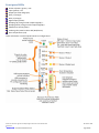
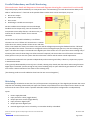
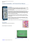
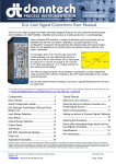
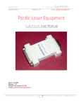
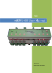
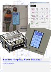
Filename: High Current Output Signal Converter User Manual.docx Version: 0.a Date: 02 October 2014 HighCurrentOutputSignalConverter(HCOSC)UserManual
[This document is in process of being written and will be updated when the units are available] We have been manufacturing various devices used for control of hydraulic valves and this is the recent revision specifically designed to incorporate all the features required in a modern hydraulic valve controller. The unit comes in several different models and is designed to provide either a linear voltage or current output of up to ±24 V at up to ±350 mA or ±12 V at up to ±1.25 A. The output can be either constant voltage or constant current which is user‐configurable. Using multiple, powerful internal processors we can adapt some of the features to suit specific applications. Main features: High speed, step response less than 1 mS. Various process signal inputs, direct resistance/joystick connection. High speed ModBus connection for integration into control systems. Multi‐way isolation between input, output power supply, communications, feedback, digital input and relay outputs. Compact DIN rail mounting. (a model with ruggedized aluminium IP66 enclosure for mobile applications will be available in the future or on demand). All controls can be adjusted on‐site using front panel trimpots and then locked with side access DIP switch. Very many settings can be selected using DIP switches without the requirement for PC software. Unit can also be completely configured using the USB connection and configuration software. Completely configurable. Designed for parallel redundant operation either in a Master/Slave configuration or using an external supervising controller. Filename: Filename: High Current Output Signal Converter User Manual.docx Version: 0.a ©
danntech – PROCESS INSTRUMENTATION 02 October 2014 Page 1 of 8 BasicDesignPhilosophy
This device is an upgrade of the device we have made for some years, which was actually crap. The firmware in the old one was crappy. This new design has been changed to cater for Signal Conversion with higher output current and voltage as well as Hydraulic Valve Control. The primary design is focussed on the hydraulic valve application. I have done the design so that all the basic setting can be configured by an “enlightened” user in the field following instructions in the user manual without any fancy equipment. PC, IPad or smartphone configuration will also be possible using the USB interface later – this will enable more complex setup to be done where DIP switches and LEDs are unable to provide all the features or are too complex to use. To put into context the various offerings we have and need please see the document “Current Output Signal Converter Range”. (i.e. not switched mode or pulse output type). GeneralDescription
This unit is designed to provide either a linear voltage or current output of up to ±11 V [I think this may need to be able to be higher at up to ±30 V for 24 V solenoids] and currents up ±350 mA. [I don’t think that we can fit on two of these DC to DC converters] The output can be either constant voltage or constant current which is user‐configurable. InputsandOutputs
Standard inputs, which are DIP switch selectable, are: 4‐20 mA, 0‐20 mA, 0‐100 mV, 0‐1 V, 0‐10 V, 0‐100 V, ±1 V, ±10 V, (others possible and you can calibrate to any values within each standard range). Resistance – up to 10 kΩ, user rangeable. Standard outputs, DIP selectable are: 4‐20 mA, ±10 mA , ± 50 mA , ± 100 mA, ± 250 mA, ± 350 mA GeneralDescription
The unit is delivered as required on order but almost all the input, output, alarms and LED functions are user configurable using DIP switches and single push button (PB). In the future we will also provide a software interface or a small configurator which can be plugged into the device to make configuration quicker and easier. Input ranges can be set up using DIP switch selection and then can be re‐ranged anywhere within the selected range using the push button is used to capture the desired input minimum and desired input maximum. You can of course just use as delivered or by selecting any of the preset configurations. Input resolution 16 bit (may be 24 bit). Output resolution 16 bits. Step response of 2 mS or less (500 Hz). Four way isolation of up to 1000 VDC between input, output, auxiliary power supply and communications (if fitted). The output can also be ranged to suit the user application using two trimpots and the push button used to capture the desired output settings or it be simply used as configured for delivery or using any of the presets. Devices can be connected up in parallel or series to provide higher output currents or voltages and parallel redundancy if required. Filename: Filename: High Current Output Signal Converter User Manual.docx Version: 0.a ©
danntech – PROCESS INSTRUMENTATION 02 October 2014 Page 2 of 8 Power loss for a converter at 6W minus load power, so for a 10Ω load at 250mA = 6 – 0.625 = 5.3W; for 40Ω load at 250mA = 6 – 2.5=3.5W. In the case of higher voltage output parts – say ±30V (maximum for OPA541) then max heatsink power dissipation can be 12 W (10 V x .4 A). High quality plug‐in screw terminals which can accommodate wire 2.5m2 cross‐section. Dimensions: Width = 45mm; Height (top to bottom) = 110mm; Depth (off rail from chassis plate to front)=125mm Current requirements are 300mA max, at 24VDC supply with some switch‐on surge, we don’t know this yet but my guess is around 500mA for a few milliseconds. We have an internal time delay fuse – soldered on PCB, so external fusing is not needed. This functional diagram will be updated with the final documentation. TrimpotControls
Setpoint (for applications where a fixed variable setpoint is used to control the output) – P1. Bias (to adjust the zero output value AKA Zero) – P2. Imax (to adjust the maximum output current – AKA Span) – P3 Ramp Up (controls the ramp up time, range selected using DIP switches off, 0‐1S, 0‐10S, 0‐100S) – P4 Ramp Down (controls the ramp up time, range selected using DIP switches off, 0‐1S, 0‐10S, 0‐100S) – P5 Dither Amplitude (controls the amount of dither added to the output signal 0 to 20% ‐ this is a ±addition so that the average output remains as set) – P6 Dither Frequency (adjustable from 50 to 800 Hz) – P7 Seven trimpots which can be locked or unlocked by dipswitch. Filename: Filename: High Current Output Signal Converter User Manual.docx Version: 0.a ©
danntech – PROCESS INSTRUMENTATION 02 October 2014 Page 3 of 8 FrontpanelLEDs
Power In/Status (green) ‐ LDS Input (yellow) ‐ LDI Output (bi‐colour bargraph) Relay 1 (orange) – Relay 2 (orange) – Digital Input (yellow) ‐ Ramping Up (orange inside output bargraph) – Ramping Down (orange inside output bargraph) ‐ USB/Comms Activity (blue) ‐ Isolating relay state bi‐colour led (Red/Green) Over‐temperature (red) There will also be a recessed push button for configuration ? Filename: Filename: High Current Output Signal Converter User Manual.docx Version: 0.a ©
danntech – PROCESS INSTRUMENTATION 02 October 2014 Page 4 of 8 Versions/Models
Basic Model: Terminal 1 2 3 4 5 6 7 8 B1 B2 B3 B4 B5 Function Power In – Power In + Input ‐ Input + Relay 1 B Relay 1 A Output ‐ Output + Power In – Power In + Tx Rx GND Location Plug‐In Screw Terminal Top/Front Plug‐In Screw Terminal Bottom/Front Rear Backplane/Bus Connector for Multi‐Drop, Plug‐In Systems Enhanced Models (includes two additional plug‐in screw terminals): Terminal 9 10 11 12 13 14 15 16 Function Feedback ‐ Feedback + Digital Input ‐ Digital Input + Relay 2 B Relay 2 A RS485 ‐ RS485 + Location Plug‐In Screw Terminal Top/Back Plug‐In Screw Terminal Bottom/Back PowerOutputandPowerSupplies
Input Output Output DC to DC Converter Input DC to DC Converter 9‐36VDC 9‐36VDC 18‐36VDC 18‐36VDC 9 – 18 VDC 18 – 36 VDC 36 – 75 VDC ±180 mA; ±12 V ±180 mA; ±25 V ±380 mA; ±12 V ±380 mA; ±25 V ±1.25 A; ±12 V ±1.25 A; ±12 V ±1.25 A; ±12 V 1 x TRACO TEN 5 – 2423WI 2 x TRACO TEN 5 – 2423WI 1 x TRACO THD 12 – 2423 2 x TRACO THD 12 – 2423 1 x TRACO TEN 40 – 1223 1 x TRACO TEN 40 – 2423 1 x TRACO TEN 40 – 4823 Filename: Filename: High Current Output Signal Converter User Manual.docx Version: 0.a ©
danntech – PROCESS INSTRUMENTATION 02 October 2014 Page 5 of 8 HowitWorks
The rear backplane connector can be used in future options for CAN Bus (or TTL RS232) multi‐drop communications where several units are used in conjunction with a RMF Controller to co‐ordinate the communications. (The RMF controller can communicate using RS485, RS232 or USB and later we can include an Ethernet interface). This design version has dual processors to be able to provide all the required features with a suitable response time. Micro‐Controller #1 will do the input, control and communications passing only an output value to Micro‐Controller #2. Micro‐Controller #2, the output controller, will do the ramping, dither, output control, output feedback, over‐
temperature control, output monitoring and fault monitoring functions. We have added a hardware watchdog which requires a regular pulse from each of the micro‐controllers to keep the watchdog happy and the output relay enabled. In addition to the hardware watchdog each processor will also have internal watchdogs which will reset the processor should anything disrupt the code execution. The hardware watchdog is a “last resort” function to ensure that a malfunctioning unit disconnects itself from control circuit. The output feedback is also an addition and this is a high impedance amplifier/interface to the output designed so that a failure of this amplifier can have no effect on the output due to the high impedance connection. This provides a way for the output micro to monitor the control circuit even when disconnected and act accordingly. Relays 1 and 2 can be set up for various alarm conditions, the relay outputs are specified at 30 VDC up to 1 A. The digital input is an opto‐coupled input at 9 to 30 VDC and can be used to reset alarms and to provide some output control functions and the interlinking of units in “Follow Me” mode. The Feedback output is designed to output 4‐20 mA or 0‐10 V which is in proportion to either the output current or output voltage (DIP switch selectable). This output is galvanically isolated from the input, power supply, output and communications. The RS485 communications is register based using our simple ASCII RMF protocol with Modbus also available. The Alarm Relays and Alarm LEDs are configurable and can be set up to switch low to high or high to low and can be normally open or normally closed. The LEDs can be used to indicate Alarm Relay status in either normally open or normally closed configurations. The Alarm LEDs will flash at different rates to indicate which alarm is active during the Alarm delay time (if selected). Alarm values and various settings are user configurable using DIP switches and single push button (PB) capture function. The Input LED can be configured to provide a quick indication of the input signal state, off, slow flash, on and fast flash. Input LED values can be setup by injecting and using the single push button (PB) capture function. Dither control is provided for Hydraulic Valve applications. Adjustable frequency from 50 to 800 Hz and amplitude adjustable from 0 to 20% of output range using front panel trimpots. An output control relay is included for fail‐safe applications so that the two or more controllers can be used in parallel with the facility to isolate the output in the event of a module failure. Will be nice to have a USB connection on the front of the unit to be able to upload new firmware and to plug in a PC or configurator (could be a Bluetooth gadget or wireless to link to an Ipad or phone app) Filename: Filename: High Current Output Signal Converter User Manual.docx Version: 0.a ©
danntech – PROCESS INSTRUMENTATION 02 October 2014 Page 6 of 8 ParallelRedundancyandFaultMonitoring
[thisneedsmoredetailanddiagramrevisionsanddiagramsshowingtheconnectionsforeachmode]
To provide proper parallel redundancy we incorporate some “self‐monitoring” for each device and the ability to be able to “self‐disconnect”. If we look at the possible failure modes which can be acted upon, they are: 1.
2.
3.
4.
No current output. Max current output. Short circuit. Oscillating or variable current output. We also include internal output current and voltage feedback and an output relay, then the firmware can incorporates some safety features. The alarm relay can indicate the of module “health” for an external controller. So version V0.1 of parallel redundancy is as follows: The units can run as “follow me” where there is a master and a slave. The master provides all the current and does all the control while the slave just monitors the input and the voltage output using hiZ feedback and the “All Good” relay (on 5&6) of the master. The master is configured so that if the digital input goes low, then the isolating relay opens. The slave RL2 output is connected to the digital input of the master so it can open the master isolating relay if necessary (the sense of these things can all be inverted if required). The slave takes over all functions and sends an alarm (opens its RL1) to alert the system that there has been a failure and the master needs replacement. In autonomous mode each unit operates independently and monitoring and safety is done by a supervisory system. In autonomous mode: If all is good (as determined by micro #2), RL1 is closed, isolating relay closed, RL2 does alarm and warning functions. Digital input “activated” (can be set high or low) causes isolating relay to open and all that goes with that. It will be nice to have a direct indication of the status of the isolating relay. [This drawing needs more info added to show how the unit can work together] Watchdog
The watchdog is included to ensure that if any of the processors stop working or if the digital input dictates the unit to stop then the watchdog automatically will open the isolation relay and disconnect the output from the load. This will ensure that the units can be used in a parallel redundant mode in master/slave configuration or independently. Inputs: 1.
2.
3.
4.
5.
6.
Power supply detected. Input processor is alive (toggle detect). Output processor is alive (toggle detect). Input processor digital input. Output processor digital input. External digital input can be 1=healthy, or inverted 0=healthy or disabled. Filename: Filename: High Current Output Signal Converter User Manual.docx Version: 0.a ©
danntech – PROCESS INSTRUMENTATION 02 October 2014 Page 7 of 8 Will probably be good to have a power up delay built in? Where all is assumed to be good, and output connected by default. Can be say for 100mS to allow all the inputs to become stable. Alternately the isolating relay can be kept open for the power –up delay so as to keep disconnected from the load until everything has settled? I think use a simple 14 or 16 pin PIC to do this function. danntech cc
Reg. No. CK1986/15338/23 Tel International: +27 11 7921239 Tel National: 011 7921239 Fax International: +27 11 7924687 Fax National: 011 7924687 e‐mail: [email protected] P O Box 1023, Fontainebleau, 2032 Republic of South Africa www.danntech.com danntech Ltd
Co. No. 6510211 15 College Close, Hamble‐le‐Rice Southampton, Hampshire SO31 4QU United Kingdom Tel: 075 9069 1824 e‐mail: [email protected] www.danntech.com Danntech makes no warranty of any kind with regard to this material, including, but not limited to, the implied warranties of merchantability and fitness for a particular purpose. Danntech shall not be liable for errors contained herein or for incidental or consequential damages in connection with the furnishing, performance or use of this material. This document contains proprietary information, which is protected by copyright. No part of this document may be photocopied, reproduced, or translated into another language without the prior written consent of Danntech. The information in this document is subject to change without notice. Filename: Filename: High Current Output Signal Converter User Manual.docx Version: 0.a ©
danntech – PROCESS INSTRUMENTATION 02 October 2014 Page 8 of 8