1
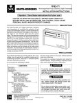
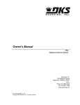
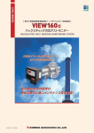
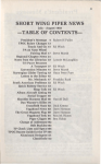
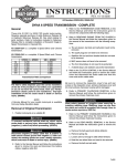
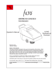
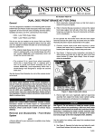
DRIVE SYSTEM Lifting the Machine for Service 1. Place two pieces of approximately 2” (5.08cm) thick wood blocks directly behind both tracks (Fig. 1261). 4. Raise the rear of the machine, remove the two wood blocks and place a jack stand under each corner of the frame (Fig. 1263). Fig 1261 Fig 1263 PICT-4248 PICT-4245 5. Raise the hydraulic floor jack approximately 15” (38.10cm) and position it at the front of the machine (Fig. 1264). 2. Back the machine up onto the wood blocks. 3. Place a hydraulic floor jack under the rear frame of the machine (Fig. 1262). TX525 Service Manual Fig 1262 Fig 1264 PICT-4249 PICT-4247 Rev. 000 7-1 DRIVE SYSTEM 6. Start the machine and raise the loader arm enough to clear the hydraulic floor jack. Place the floor jack directly below the mount plate and lower the loader arm onto the hydraulic floor jack. Continue lowering the loader arm to raise the tracks off the ground (Fig. 1265). 8. Lower the hydraulic floor jack so the machine rests on the jack stands. Lower the loader arms to the resting position (Fig. 1267). Fig 1265 PICT-4250 Fig 1267 PICT-4253 9. Make sure the machine is securely supported by the jack stands. 7. Place two jack stands under the front frame (Fig. 1266). 7-2 Fig 1266 PICT-4251 Rev. 000 TX525 Service Manual DRIVE SYSTEM Track Guide Alignment Alignment Tool (Toro p/n: 110-0069) (Fig. 1268): 3. Wide track models only: Slide a washer/tensioner wheel assembly onto the tensioner arm wheel shaft. Install a nut to secure (Fig. 1270). Fig 1268 DSC-0624 Fig 1270 PICT-4483 4. Insert the notched end of the alignment tool into the drive wheel spacer (Fig. 1271). 1. Remove the track. Refer to “Wide Track Removal” on page 7-68 or “Narrow Track Removal” on page 7-72. 2. Loosen the 4 bolts securing the track guide to the mainframe (Fig. 1269). TX525 Service Manual Fig 1269 Fig 1271 PICT-4485 PICT-4482 Rev. 000 7-3 DRIVE SYSTEM 5. Secure the notched end with the pin (Fig. 1272). Fig 1272 7. Torque the 4 track guide mounting bolts to 75 ft-lbs. (102 Nm) (Fig. 1274). PICT-4484 6. Rotate the tool and move the track guide as necessary until the tool fits into the track guide channel. Secure the end of the alignment tool with a strap (Fig. 1273). Fig 1273 Fig 1274 PICT-4493 8. Remove the alignment tool. 9. Wide track models only: Remove the nut and washer/tensioner wheel assembly from the tensioner arm wheel shaft (Fig. 1275). PICT-4488a Fig 1275 PICT-4483 10. Install the track. Refer to “Wide Track Installation” on page 7-70, or “Narrow Track Installation” on page 7-73. 7-4 Rev. 000 TX525 Service Manual DRIVE SYSTEM Belt Replacement 6. Support the hood and remove the prop rod (Fig. 1277). Belt Removal 1. Position the traction unit on a flat surface. 2. Remove the ignition key. 3. Apply the parking brake. 4. Raise the hood. 5. Remove the hairpin cotter from the hood prop rod (Fig. 1276). Fig 1277 Belt 003 7. Using a 1/2” wrench, remove the 2 lower heat shield screws (Fig. 1278). Fig 1276 Belt 001 TX525 Service Manual Rev. 000 Fig 1278 Belt 002 7-5 DRIVE SYSTEM 8. Using a 3/16” Allen wrench, remove the 2 upper heat shield screws (Fig. 1279). 10. Using a spring tool, remove the idler spring from its post (Fig. 1281). Fig 1279 Belt 004 9. Remove the heat shield (Fig. 1280). 7-6 Fig 1280 Fig 1281 Belt 007 11. Remove the belt from the right and left hydraulic traction pump pulleys (Fig. 1282). Belt 005 Rev. 000 Fig 1282 Belt 008 TX525 Service Manual DRIVE SYSTEM 12. Remove the rear access cover (Fig. 1283). Fig 1283 14. Remove the gas tank hold down bracket (Fig. 1285). Belt 006 13. Using a 1/2” wrench and 1/2” socket combination, remove the gas tank hold down bracket bolt and nut (Fig. 1284). TX525 Service Manual Belt 010 15. Using a 5/8” socket combination, remove the 2 hydraulic pump mount plate bolts (Fig. 1286). Fig 1284 Fig 1285 Fig 1286 Belt 013 Belt 009 Rev. 000 7-7 DRIVE SYSTEM Belt Installation 16. Rotate the hydraulic pump clockwise and pull the hydraulic pump outward to separate the coupling sleeve and the hub sleeve. This will permit belt removal (Fig. 1287). Fig 1287 1. Pull the hydraulic pump outward to create enough clearance between the coupling sleeve and the hub sleeve to allow for belt installation (Fig. 1289). Belt 012 Fig 1289 Belt 015 17. Remove the belt (Fig. 1288). 2. Install the belt onto the engine pulley and the right and left hydraulic traction pump pulleys (Fig. 1290). Fig 1288 Belt 015 7-8 Rev. 000 Fig 1290 Belt 014 TX525 Service Manual DRIVE SYSTEM 3. Using a spring tool, install the idler spring onto its post (Fig. 1291). 4. Rotate and push the hydraulic pump by hand until the coupling sleeve properly meshes with the hub sleeve recessed in the engine pulley (Fig. 1293). Note: Do not use the hydraulic pump mount plate bolts to draw the coupling sleeve into the hub sleeve. Doing so could result in the snap ring sliding out of its groove on the hub coupling. This will result in the loss of hydraulics. Fig 1291 Belt 007 Belt Routing (rear view) (Fig. 1292): A B E A. LH pump pulley B. Drive belt C. RH pump pulley TX525 Service Manual Fig 1292 C Fig 1293 Belt 012 D TX525 belt routing D. Idler pulley E. Engine pulley Rev. 000 7-9 DRIVE SYSTEM 5. Using a 5/8” socket, install and torque the 2 hydraulic pump mount plate bolts to 50 ft-lbs. (67.8 Nm) (Fig. 1294). 7. Install the rear access cover (Fig. 1296). Fig 1294 Fig 1296 Belt 006 Belt 018 8. Position the heat shield (Fig. 1297). 6. Using a 1/2” wrench and socket, install the gas tank hold down bracket (Fig. 1295). 7-10 Fig 1295 Fig 1297 Belt 005 Belt 009 Rev. 000 TX525 Service Manual DRIVE SYSTEM 9. Using a 3/16” Allen wrench, install and tighten the 2 upper heat shield screws (Fig. 1298). 11. Support the hood and install the prop rod (Fig. 1300). Fig 1298 Belt 004 10. Using a 1/2” wrench, install and tighten the 2 lower heat shield screws (Fig. 1299). TX525 Service Manual Fig 1299 Belt 002 Fig 1300 Belt 003 12. Install the hairpin cotter (Fig. 1301). Rev. 000 Fig 1301 Belt 001 7-11 DRIVE SYSTEM Idler Arm Replacement 5. Using a 3/16” Allen wrench, remove the top 2 screws. Using a 1/2” socket, remove the bottom 2 screws securing the heat shield to the tower (Fig. 1304). Idler Arm Removal 1. Shut engine off, apply parking brake, and remove ignition key. 2. Lift the engine hood assembly. 3. Remove the hairpin cotter from the prop rod (Fig. 1302). Fig 1304 PICT-5258 6. Remove the heat shield (Fig. 1305). Fig 1302 Belt 001 4. Remove the prop rod (Fig. 1303). 7-12 Fig 1303 Fig 1305 Belt 005 Belt 003 Rev. 000 TX525 Service Manual DRIVE SYSTEM 7. Remove the rear access panel (Fig. 1306). Fig 1306 9. Using a spring tool, remove the idler spring from its post (Fig. 1308). PICT-4505a 8. Using a 3/8” socket, remove the 3 screws securing the right hand support panel to the tower assembly. Remove the right hand support panel (Fig. 1307). Fig 1308 PICT-5360 10. Using a 1/2” socket and wrench, remove the nut securing the idler arm assembly to the tower (Fig. 1309). Note: The nut is located on the back side of the tower behind the loader valve. Fig 1307 PICT-4504 TX525 Service Manual Rev. 000 Fig 1309 PICT-5370 7-13 DRIVE SYSTEM 11. Remove the idler arm assembly from the unit (Fig. 1310). 13. Inspect the idler pulley bearing and the two flange bushings. Replace if worn or damaged (Fig. 1312). E F DSC-3321 (found in the TX420/425 F C manual – “Drive” section, pg 8-55) G H D I A B Fig 1310 PICT-5371 12. Remove the spring and rubber spring retainer from the idler assembly and slide the rubber spring retainer off the spring (Fig. 1311). 7-14 Fig 1311 A. B. C. D. E. Fig 1312 Carriage bolt Idler arm assembly Pulley Nut Nut F. G. H. I. CLR DSC-3321 Flange bushings (2) Mounting spacer Washer Bolt PICT-5374a Rev. 000 TX525 Service Manual DRIVE SYSTEM Idler Arm Assembly Installation 3. Slide a spring tool through the rubber spring retainer. Hook the idler spring to the spring tool (Fig. 1315). 1. Position the idler arm assembly in the unit so the drive belt is routed between the pulley and the idler arm spring post (Fig. 1313). Fig 1313 PICT-5373 Fig 1315 PICT-5376a 4. Pull the idler spring approximately half way into the rubber spring retainer (Fig. 1316). 2. Slide the idler arm down and position it against the tower, inserting the idler mounting bolt through the mounting hole in the tower. Using a 1/2” socket and wrench, install a nut onto the idler assembly bolt securing it to the tower. Ensure the idler arm rotates freely (Fig. 1314). TX525 Service Manual Fig 1314 Fig 1316 PICT-5377a PICT-5370 Rev. 000 7-15 DRIVE SYSTEM 5. Hook the idler spring to the idler arm spring post (Fig. 1317). Fig 1317 8. Position the right hand support panel to the tower. Using a 3/8” socket, install 3 screws to secure the right hand support panel to the tower assembly (Fig. 1319). PICT-5378 Fig 1319 PICT-4504 6. Align the belt with the idler pulley. 7. Using a spring tool, install the idler spring onto its post (Fig. 1318). 7-16 Fig 1318 9. Install the rear access panel (Fig. 1320). PICT-5379 Rev. 000 Fig 1320 PICT-4505a TX525 Service Manual DRIVE SYSTEM 10. Position the heat shield (Fig. 1321). Fig 1321 12. Install the prop rod (Fig. 1323). Belt 005 11. Using a 3/16” Allen wrench, install the top 2 screws. Using a 1/2” socket, install the bottom 2 screws securing the heat shield to the tower (Fig. 1322). TX525 Service Manual Fig 1322 Belt 003 13. Install a hairpin cotter into the prop rod (Fig. 1324). Fig 1323 Fig 1324 Belt 001 PICT-5258 Rev. 000 7-17 DRIVE SYSTEM Right Hydrostatic Pump Replacement Right Hydrostatic Pump Removal 3. Using a 3/8” socket, remove the 6 screws that secure the left and right rear cover support panels to the tower assembly (3 screws per panel). Remove the panels (Fig. 1326). Note: Cleanliness is a key factor in a successful repair of any valve system. Thoroughly clean all exposed surfaces prior to any type of maintenance. Cleaning all parts by using a solvent wash and air drying is usually adequate. As with any precision equipment, all parts must be kept free of foreign material and chemicals. Protect all exposed sealing areas and open cavities from damage and foreign material. Upon removal, all seals, o-rings, and gaskets should be replaced. During installation, lightly lubricate all seals, o-rings, and gaskets with clean petroleum jelly prior to assembly. Protect the inner diameter of seals and o-rings from damage during assembly by covering the shaft machined features with plastic wrap or equivalent. 1. Raise the machine and set it on jack stands. Refer to “Lifting the Machine for Service” on page 7-1. 2. Remove the rear access panel (Fig. 1325). Fig 1326 PICT-4504 4. Using 3/4” and 1/2” sockets, remove the 7 bolts and nuts securing the rear frame cover to the frame and fuel tank bracket. Remove the rear frame cover (Fig. 1327). Note: The rear of the machine may have to be lifted to reposition the jack stands so that the rear frame cover can be removed. Fig 1325 PICT-4505 7-18 Rev. 000 Fig 1327 PICT-4259 TX525 Service Manual DRIVE SYSTEM 5. Remove the fuel tank bracket (Fig. 1328). Fig 1328 7. Mark the suction fuel line and tank fitting with an “S” and the return fuel line and tank fitting with an “R” (Fig. 1330): S - Fuel suction line R - Fuel return line PICT-5626 6. Disconnect the two wires (black and orange) from the fuel sending unit located on the top of the fuel tank (Fig. 1329). Fig 1330 PICT-4263 8. Slide the 2 fuel hose clamps down the fuel lines away from the fuel tank fittings (Fig. 1331). Fig 1329 PICT-4262a TX525 Service Manual Rev. 000 Fig 1331 PICT-4264 7-19 DRIVE SYSTEM 9. Slide the 2 fuel lines off the fuel tank fittings. Remove the fuel tank (Fig. 1332). 11. Remove the left hand panel from the control panel assembly (Fig. 1334). Fig 1332 PICT-4265 10. Using a 3/8” socket, remove the 4 self-tapping screws securing the left hand panel to the control panel assembly (Fig. 1333). Fig 1334 PICT-4601 12. Using a 3/8” socket, remove the 3 self-tapping screws that secure the right panel to the control panel assembly. Using a 3/8” socket and a 7/16” socket, remove the bolt and nut securing the lower left corner of the right panel to the control panel assembly (Fig. 1335). A A B Fig 1333 A PICT-4600 Fig 1335 PICT-4341 A. Self-tapping screw (3) B. Bolt and nut 7-20 Rev. 000 TX525 Service Manual DRIVE SYSTEM 13. Remove the right hand panel from the control panel assembly (Fig. 1336). Fig 1336 C. Case drain line (Fig. 1338). Fig 1338 PICT-4639a PICT-4269 14. Mark the hydrostatic pump fittings and lines as follows: A. Inlet line from the left hand hydrostatic pump (Fig. 0000). D. Right hand wheel motor port (Fig. 1339). E. Left hand wheel motor port (Fig. 1339). B. Inlet line from the hydraulic oil filter (Fig. 1337). TX525 Service Manual Fig 1337 Fig 1339 PICT-4640 PICT-4637 Rev. 000 7-21 DRIVE SYSTEM 15. Mark the hydraulic pump wheel motor hoses and fittings with the letters D and E (Fig. 1340). 17. Mark the tandem pump, T-fitting and hose with the letter “G” (Fig. 1342). Fig 1340 PICT-4747 Fig 1342 PICT-4737 16. Mark the tandem pump, hose and fitting running to the 2 spool valve with a letter “F” (Fig. 1341). 18. Mark the tandem pump test port fitting with the letter “H” (Fig. 1343). 7-22 Fig 1341 PICT-4736 Rev. 000 Fig 1343 PICT-4740a TX525 Service Manual DRIVE SYSTEM 19. Using a 15/16” wrench, disconnect the right hand hydrostatic pump lines (just marked) as follows: C. Case drain line (Fig. 1346). A. Inlet line from the hydraulic oil filter (Fig. 1344). Fig 1344 D. Hydraulic hose running from the “D” port on the right hand hydrostatic pump to the upper fitting on the left wheel motor (Fig. 1347). TX525 Service Manual Fig 1345 PICT-4643a PICT-4636 B. Inlet line to the left hand hydrostatic pump (Fig. 1345). Fig 1346 Fig 1347 PICT-4644 PICT-4641 Rev. 000 7-23 DRIVE SYSTEM E. Hydraulic hose running from the “E” port on the hydrostatic pump to the lower fitting on the left wheel motor (Fig. 1348). Fig 1348 PICT-4645 20. Using a 15/16” wrench, remove the wheel motor hose fittings marked “D” from the right hand hydraulic pump (Fig. 1349). 7-24 21. Using a 15/16” wrench, remove the wheel motor hose fittings marked “E” from the right hand hydraulic pump (Fig. 1350). PICT-4751a 22. Using a 1-1/8” wrench, remove the hydraulic hose marked “F” from the tandem pump fitting (Fig. 1351). Fig 1349 Fig 1350 Fig 1351 PICT-4734 PICT-4750 Rev. 000 TX525 Service Manual DRIVE SYSTEM 23. Using a 15/16” wrench, remove the hose from the T-fitting marked “G” on the tandem pump (Fig. 1352). Fig 1352 25. Remove the T-fitting marked “G” from the tandem pump (Fig. 1354). Note: Cap all hydraulic lines and fittings to prevent debris from entering system. PICT-4738a 24. Using a 15/16” wrench, remove the test port fitting “H” from the T-fitting marked “G” (Fig. 1353). Fig 1353 PICT-4742a 26. Using a 1/2” socket and wrench, remove the nut and bolt securing the steering linkage to the right hand pump control arm (Fig. 1355). PICT-4741a TX525 Service Manual Fig 1354 Rev. 000 Fig 1355 PICT-4752 7-25 DRIVE SYSTEM 30. Using a 1/2” wrench, remove the 2 lower heat shield screws (Fig. 1358). 27. Raise the hood. 28. Remove the hairpin cotter from the hood prop rod (Fig. 1356). Fig 1356 31. Using a 3/16” Allen wrench, remove the 2 upper heat shield screws (Fig. 1359). 7-26 Fig 1357 Belt 002 Belt 001 29. Support the hood and remove the prop rod (Fig. 1357). Fig 1358 Fig 1359 Belt 004 Belt 003 Rev. 000 TX525 Service Manual DRIVE SYSTEM 32. Remove the heat shield (Fig. 1360). Fig 1360 34. Remove the belt from the right and left hydraulic traction pump pulleys (Fig. 1362). Belt 005 33. Using a spring tool, remove the idler spring from its post (Fig. 1361). Fig 1361 Belt 008 35. Secure the pulley. Using a 5/8” socket, remove the center nut and washer retaining the pulley to the right hand hydrostatic pump shaft (Fig. 1363). Belt 007 TX525 Service Manual Fig 1362 Rev. 000 Fig 1363 PICT-4647 7-27 DRIVE SYSTEM 36. Install a special pulley puller (Toro p/n: 112-2557) onto the right hand hydrostatic pulley (Fig. 1364). 38. Remove the key from the hydrostatic pump shaft keyway (Fig. 1366). Fig 1364 PICT-4593a 37. Remove the right hand pulley from the hydrostatic pump shaft (Fig. 1365). Fig 1365 PICT-4650 39. Using a 3/4” socket and wrench, remove the top bolt and nut securing the right hand hydrostatic pump to the tower frame. Loosen the lower nut and bolt securing the right hand hydrostatic pump to the tower frame (Fig. 1367). PICT-4648 7-28 Fig 1366 Rev. 000 Fig 1367 PICT-8900 TX525 Service Manual DRIVE SYSTEM Right Hydrostatic Pump Installation 40. Remove the right hand hydrostatic pump from the tower frame (Fig. 1368). 1. With the lower pump mounting bolt and nut loosely installed in the tower frame, position the right hand hydrostatic pump so the pump shaft is inserted through the frame (Fig. 1370). Fig 1368 PICT-4753 41. If replacing the pump, transfer all markings and fittings to the new pump (Fig. 1369). Fig 1370 PICT-4753 Note: Do not install the fittings marked D and E. 2. Using a 3/4” socket and wrench, install the top bolt and nut. Tighten the lower bolt and nut securing the right hand hydrostatic pump to the tower frame (Fig. 1371). Fig 1369 PICT-4754a 42. If repairing/rebuilding the pump, refer to the HydroGear BDP-10A/16A/21L Hydrostatic Pumps Service and Repair Manual (Toro Form No. 492-4789). TX525 Service Manual Rev. 000 Fig 1371 PICT-8900 7-29 DRIVE SYSTEM 3. Install a key into the hydrostatic pump shaft keyway (Fig. 1372). Fig 1372 PICT-4650 Note: The pulley has a tapered through hole and a thicker flange on one side than the other (Fig. 1373). 7-30 Fig 1373 PICT-4662a 4. Slide the pulley onto the right hand hydrostatic pump shaft with the thicker flange side facing toward the pump (Fig. 1374). Fig 1374 PICT-4758 5. Slide a washer onto the pump shaft (Fig. 1375). Rev. 000 Fig 1375 PICT-4760 TX525 Service Manual DRIVE SYSTEM 8. Route the belt around the engine pulley and the right and left hydrostatic pump pulleys (rear view) (Fig. 1378). 6. Install a nut to secure the pulley to the right hand hydrostatic pump shaft (Fig. 1376). A Fig 1376 PICT-4761 7. Torque the nut to 260 + 40 in-lbs. (29.38 + 4.5 Nm) (Fig. 1377). B E A. LH pump pulley B. Drive belt C. RH pump pulley Fig 1378 C D TX525 belt routing D. Idler pulley E. Engine pulley 9. Install the idler spring onto its post (Fig. 1379). Fig 1377 PICT-4763 TX525 Service Manual Rev. 000 Fig 1379 Belt 007 7-31 DRIVE SYSTEM 10. Position the heat shield (Fig. 1380). Fig 1380 12. Using a 1/2” wrench, install the 2 lower heat shield screws (Fig. 1382). Belt 005 11. Using a 3/16” Allen wrench, install the 2 upper heat shield screws (Fig. 1381). 7-32 Fig 1381 Belt 004 Fig 1382 Belt 002 13. Support the hood and install the prop rod (Fig. 1383). Rev. 000 Fig 1383 Belt 003 TX525 Service Manual DRIVE SYSTEM 17. Install the T-fitting marked “G” into the tandem pump (Fig. 1386). 14. Install the hairpin cotter (Fig. 1384). Fig 1384 Belt 001 15. Lower the hood. 16. Using a 1/2” socket and wrench, install the nut and bolt securing the steering linkage to the right hand pump control arm (Fig. 1385). TX525 Service Manual Fig 1385 PICT-4742a 18. Using a 15/16” wrench, install the test port fitting “H” onto the T-fitting marked “G” (Fig. 1387). Fig 1386 Fig 1387 PICT-4741a PICT-4752 Rev. 000 7-33 DRIVE SYSTEM 19. Using a 15/16” wrench, install the hose marked “G” onto the T-fitting marked “G” on the tandem pump (Fig. 1388). Fig 1388 21. Loosely install the wheel motor hose fittings marked “D” and “E” into the right hand hydraulic pump ports marked “D” and “E” so they are positioned at approximately 8:00 (D) and 9:00 (E) clock positions (Fig. 1390). PICT-4738a 20. Using a 1-1/8” wrench, install the hydraulic hose marked “F” onto the tandem pump fitting (Fig. 1389). Fig 1389 PICT-4755 22. Using a 15/16” wrench, connect the right hand hydrostatic pump lines as follows: E. Wheel motor hose marked “E” to the fitting marked “E” (Fig. 1391). PICT-4734 7-34 Fig 1390 Rev. 000 Fig 1391 PICT-4645 TX525 Service Manual DRIVE SYSTEM B. Inlet line from the left hand hydrostatic pump marked “B” to the fitting marked “B” (Fig. 1394). D. Wheel motor hose marked “D” to the fitting marked “D” (Fig. 1392). Fig 1392 PICT-4644 TX525 Service Manual Fig 1393 PICT-4643a PICT-4641 A. Inlet line from the hydraulic oil filter marked “A” to the fitting marked “A” (Fig. 1395). C. Case drain line marked “C” to the fitting marked “C” (Fig. 1393). Fig 1394 Rev. 000 Fig 1395 PICT-4636 7-35 DRIVE SYSTEM 23. With the fitting secured, tighten the pump fitting nuts on the fittings marked “D” and “E” to the hydraulic pump (Fig. 1396). Fig 1396 Fig 1398 PICT-4601 PICT-4756 24. Using a 3/8” socket, install 3 self-tapping screws that secure the right panel to the control panel assembly. Using a 3/8” socket and a 7/16” socket, install a bolt and nut securing the lower left corner of the right panel to the control panel assembly (Fig. 1397). A 26. Using a 3/8” socket, install 4 self-tapping screws securing the left hand panel to the control panel assembly (Fig. 1399). A B 25. Position the left hand panel onto the control panel assembly (Fig. 1398). A Fig 1397 Fig 1399 PICT-4600 PICT-4341 A. Self-tapping screw (3) B. Bolt and nut 7-36 Rev. 000 TX525 Service Manual DRIVE SYSTEM 27. Slide the 2 fuel lines onto the fuel tank fittings. Note the location markings (Fig. 1400). S - Fuel suction line R - Fuel return line 29. Position the fuel tank into the rear end of the frame. Connect the two wires (black and orange) to the fuel sending unit located on the top of the fuel tank (Fig. 1402). Note: Before installing the fuel tank in the unit, disengage the park brake and start the unit. Refer to “Purging Air Procedure”, page 9-19, and check for any leaks in the hydraulic fittings and hydraulic hoses. A B Fig 1402 PICT-4262a A. Center terminal (orange wire) B. Outside terminal (black wire) Fig 1400 PICT-4265 30. Position the fuel tank bracket onto the fuel tank (Fig. 1403). 28. Position the 2 fuel hose clamps to secure the fuel lines to the fuel tank fittings (Fig. 1401). TX525 Service Manual Fig 1401 Fig 1403 PICT-5626 PICT-4264 Rev. 000 7-37 DRIVE SYSTEM 31. Position the rear frame cover to the rear end of the frame. Using 3/4” and 1/2” sockets, install 7 bolts and nuts to secure the rear frame cover to the frame and fuel tank bracket (Fig. 1404). Note: The rear of the machine may have to be lifted to reposition the jack stands so that the rear frame cover can be installed. 32. Position the left hand rear cover support panel to the tower. Using a 3/8” socket, install 3 screws to secure the left rear cover support panel to the tower assembly. Repeat to install right hand rear cover support panel (Fig. 1405). Fig 1404 PICT-4259 Fig 1405 PICT-4256 33. Install the rear access panel (Fig. 1406). Fig 1406 PICT-4505 34. Lower the machine. 7-38 Rev. 000 TX525 Service Manual DRIVE SYSTEM Left Hydrostatic Pump Replacement 4. Using 3/4” and 1/2” sockets, remove the 7 bolts and nuts securing the rear frame cover to the frame. Remove the rear frame cover (Fig. 1409). Left Hydrostatic Pump Removal 1. Raise the machine and set it on jack stands. Refer to “Lifting the Machine for Service” on page 7-1. Note: The rear of the machine may have to be lifted to reposition the jack stands so that the rear frame cover can be removed. 2. Remove the rear access panel (Fig. 1407). Fig 1407 Fig 1409 PICT-4259 PICT-4505 5. Remove the fuel tank bracket (Fig. 1410). 3. Using a 3/8” socket, remove the 6 screws that secure the left and right rear cover support panels to the tower assembly (3 screws per panel). Remove the panels (Fig. 1408). TX525 Service Manual Fig 1408 Fig 1410 PICT-5626 PICT-4504 Rev. 000 7-39 DRIVE SYSTEM 6. Disconnect the two wires (black and orange) from the fuel sending unit located on the top of the fuel tank (Fig. 1411). 8. Slide the 2 fuel hose clamps down the fuel lines away from the fuel tank fittings (Fig. 1413). Fig 1411 7. Mark the suction fuel line and tank fitting with an “S” and the return fuel line and tank fitting with an “R” (Fig. 1412): S - Fuel suction line R - Fuel return line 7-40 Fig 1412 PICT-4264 9. Slide the 2 fuel lines off the fuel tank fittings. Remove the fuel tank (Fig. 1414). Fig 1413 PICT-4262a Fig 1414 PICT-4265 PICT-4263 Rev. 000 TX525 Service Manual DRIVE SYSTEM 10. Using a 3/8” socket, remove the 4 self-tapping screws securing the left hand panel to the control panel assembly (Fig. 1415). 12. Mark the hydrostatic pump fittings and lines as follows: A. Hydraulic oil inlet from the filter (Fig. 1417). Fig 1415 PICT-4600 Fig 1416 C. Case drain line returning to the hydraulic oil tank (Fig. 1418). PICT-4601 TX525 Service Manual PICT-4603 B. Right pump case drain line and, 11. Remove the left hand panel from the control panel assembly (Fig. 1416). Fig 1417 Rev. 000 Fig 1418 PICT-4606 7-41 DRIVE SYSTEM D. Hydraulic hose running to the lower port on the right hand wheel motor and, E. Hydraulic hose running to the upper port on the right hand wheel motor (Fig. 1419). 13. Using a 15/16” wrench, disconnect the left hand hydraulic pump lines (just marked) as follows: A. Hydraulic oil inlet from the filter (Fig. 1421). Fig 1419 Fig 1421 PICT-4612 PICT-4608 B. Right pump case drain line (Fig. 1422). F. Hydraulic hose running to the lower port on the left hand wheel motor and Note: A 7/8” wrench may be used to hold the fitting while loosening the hydraulic line. G. Hydraulic hose running to the upper port on the left hand wheel motor (Fig. 1420). 7-42 Fig 1420 Fig 1422 PICT-4613 PICT-4609 Rev. 000 TX525 Service Manual DRIVE SYSTEM E. Hydraulic hose running from the “E” port on the hydrostatic pump to the lower fitting on the right wheel motor (Fig. 1425). C. Case drain line returning to the hydraulic oil tank (Fig. 1423). Fig 1423 PICT-4614 14. Using a 1-1/8” wrench, disconnect the remaining left hand hydrostatic pump lines (just marked) as follows: D. Hydraulic hose running from the “D” port on the pump to the upper fitting on the right wheel motor (Fig. 1424). TX525 Service Manual Fig 1424 PICT-4616 F. Hydraulic hose running to the lower port on the left hand wheel motor (Fig. 1426). Fig 1425 Fig 1426 PICT-4621 PICT-4615 Rev. 000 7-43 DRIVE SYSTEM G. Hydraulic hose running to the upper port on the left hand wheel motor (Fig. 1427). Note: Cap all hydraulic lines and fittings to prevent debris from entering system. Fig 1427 PICT-4623 15. Remove the nut and bolt securing the drive linkage to the left hand hydrostatic pump (Fig. 1428). 7-44 Fig 1428 PICT-4618 16. Raise the hood. 17. Remove the hairpin cotter from the hood prop rod (Fig. 1429). Fig 1429 Belt 001 18. Support the hood and remove the prop rod (Fig. 1430). Rev. 000 Fig 1430 Belt 003 TX525 Service Manual DRIVE SYSTEM 19. Using a 1/2” wrench, remove the 2 lower heat shield screws (Fig. 1431). Fig 1431 TX525 Service Manual Belt 005 22. Using a spring tool, remove the idler spring from its post (Fig. 1434). Fig 1432 Fig 1433 Belt 002 20. Using a 3/16” Allen wrench, remove the 2 upper heat shield screws (Fig. 1432). 21. Remove the heat shield (Fig. 1433). Fig 1434 Belt 007 Belt 004 Rev. 000 7-45 DRIVE SYSTEM 23. Remove the belt from the right and left hydraulic traction pump pulleys (Fig. 1435). 25. Install a pulley puller (Toro p/n: 112-2557) onto the left hand hydrostatic pump pulley (Fig. 1437). Fig 1435 Belt 008 24. Secure the pulley. Using a 5/8” socket, remove the center nut and washer retaining the pulley to the left hand hydrostatic pump shaft (Fig. 1436). 7-46 PICT-4593a 26. Remove the left hand pulley from the hydrostatic pump shaft (Fig. 1438). Fig 1436 Fig 1437 Fig 1438 PICT-4596 PICT-4592 Rev. 000 TX525 Service Manual DRIVE SYSTEM 27. Remove the key from the hydrostatic pump shaft keyway (Fig. 1439). 29. Remove the left hand hydrostatic pump from the tower frame (Fig. 1441). Fig 1439 PICT-4598 28. Using a 3/4” socket and wrench, remove the top bolt and nut securing the left hand hydrostatic pump to the tower frame. Loosen the lower nut and bolt (Fig. 1440). Fig 1440 PICT-4627 30. If replacing the pump, transfer all markings and fittings to the new pump (Fig. 1442). Fig 1441 Fig 1442 PICT-4626a PICT-4619 31. If repairing/rebuilding the pump, refer to the HydroGear BDP-10A/16A/21L Hydrostatic Pumps Service and Repair Manual (Toro Form No. 492-4789). TX525 Service Manual Rev. 000 7-47 DRIVE SYSTEM Left Hydrostatic Pump Installation 3. Install a key into the hydrostatic pump shaft keyway (Fig. 1445). 1. With the lower bolt and nut loosely installed in the tower frame, position the left hand hydrostatic pump so the pump shaft is inserted through the frame (Fig. 1443). Fig 1443 PICT-4627 Fig 1445 PICT-4598 4. The pulley has a tapered through hole and a thicker flange on one side (Fig. 1446). 2. Using a 3/4” socket and wrench, install the top bolt and nut. Tighten the lower bolt and nut securing the left hand hydrostatic pump to the tower frame (Fig. 1444). 7-48 Fig 1444 Fig 1446 PICT-4659 PICT-4619 Rev. 000 TX525 Service Manual DRIVE SYSTEM 5. Slide the left hand pulley onto the hydrostatic pump shaft with the thicker flange side facing toward the pump (Fig. 1447). 7. Install a nut to secure the pulley to the left hand hydrostatic pump shaft (Fig. 1449). Fig 1447 Fig 1449 PICT-4634 PICT-4632 6. Slide a washer onto the pump shaft (Fig. 1448). 8. Torque the nut to 260 + 40 in-lbs. (29.38 + 4.5 Nm) (Fig. 1450). TX525 Service Manual Fig 1448 PICT-4633 Rev. 000 Fig 1450 PICT-4635 7-49 DRIVE SYSTEM 9. Route the belt around the engine pulley and the right and left hydrostatic pump pulleys (rear view) (Fig. 1451). A B E A. LH pump pulley B. Drive belt C. RH pump pulley Fig 1451 11. Position the heat shield (Fig. 1453). C D Fig 1453 Belt 005 TX525 belt routing D. Idler pulley E. Engine pulley 12. Using a 3/16” Allen wrench, install the 2 upper heat shield screws (Fig. 1454). 10. Using a spring tool, install the idler spring onto its post (Fig. 1452). 7-50 Fig 1452 Fig 1454 Belt 004 Belt 007 Rev. 000 TX525 Service Manual DRIVE SYSTEM 15. Install the hairpin cotter (Fig. 1457). 13. Using a 1/2” wrench, install the 2 lower heat shield screws (Fig. 1455). Fig 1455 Belt 002 TX525 Service Manual Fig 1456 Fig 1457 Belt 001 16. Using a 1-1/8” wrench, install the left hand hydrostatic pump lines as follows: G. Hydraulic hose coming from the upper port on the left hand wheel motor (Fig. 1458). 14. Support the hood and install the prop rod (Fig. 1456). Belt 003 Rev. 000 Fig 1458 PICT-4623 7-51 DRIVE SYSTEM F. Hydraulic hose coming from the lower port on the left hand wheel motor (Fig. 1459). Fig 1459 D. Hydraulic hose coming from the lower port on the right hand wheel motor (Fig. 1461). PICT-4621 E. Hydraulic hose coming from the upper port on the right hand wheel motor (Fig. 1460). Fig 1460 PICT-4615 17. Using a 15/16” wrench, connect the left hand hydrostatic pump lines as follows: C. Case drain line returning to the hydraulic oil tank (Fig. 1462). PICT-4616 7-52 Fig 1461 Rev. 000 Fig 1462 PICT-4614 TX525 Service Manual DRIVE SYSTEM B. Right pump case drain line (Fig. 1463). Note: A 7/8” wrench may need to be used to hold the fitting while tightening the hydraulic line. 18. Position the right hand panel onto the control panel assembly (Fig. 1465). Fig 1463 Fig 1465 PICT-4269 PICT-4613 19. Using a 3/8” socket, install 3 self-tapping screws that secure the right panel to the control panel assembly. Using a 3/8” socket and a 7/16” socket, install a bolt and nut securing the lower left corner of the right panel to the control panel assembly (Fig. 1466). A. Hydraulic oil inlet from the filter (Fig. 1464). A A B Fig 1464 A PICT-4612 Fig 1466 PICT-4341 A. Self-tapping screw (3) B. Bolt and nut TX525 Service Manual Rev. 000 7-53 DRIVE SYSTEM 20. Position the left hand panel onto the control panel assembly (Fig. 1467). 22. Slide the 2 fuel lines onto the fuel tank fittings. Note the location markings (Fig. 1469). S - Fuel suction line R - Fuel return line Note: Before installing the fuel tank into the unit, disengage the park brake and start the unit. Refer to “Purging Air Procedure”, page 9-19, and check for any leaks in the hydraulic fittings and hydraulic hoses. Fig 1467 PICT-4601 21. Using a 3/8” socket, install 4 self-tapping screws securing the left hand panel to the control panel assembly (Fig. 1468). 7-54 Fig 1468 Fig 1469 PICT-4265 PICT-4600 Rev. 000 TX525 Service Manual DRIVE SYSTEM 23. Position the 2 fuel hose clamps to secure the fuel lines to the fuel tank fittings (Fig. 1470). 25. Position the fuel tank bracket onto the fuel tank (Fig. 1472). Fig 1470 PICT-4264 24. Position the fuel tank into the rear end of the frame. Connect the two wires (black and orange) to the fuel sending unit located on the top of the fuel tank (Fig. 1471). Fig 1472 PICT-5626 26. Position the rear frame cover to the rear end of the frame. Using 3/4” and 1/2” sockets, install 7 bolts and nuts to secure the rear frame cover to the frame and fuel tank bracket (Fig. 1473). Note: The rear of the machine may have to be lifted to reposition the jack stands so that the rear frame cover can be installed. A B Fig 1471 A. Center terminal (orange wire) B. Outside terminal (black wire) TX525 Service Manual PICT-4262 Rev. 000 Fig 1473 PICT-4259 7-55 DRIVE SYSTEM 27. Position the left hand rear cover support panel to the tower. Using a 3/8” socket, install 3 screws to secure the left rear cover support panel to the tower assembly. Repeat to install right hand rear cover support panel (Fig. 1474). Wheel Motor Replacement The following procedures can be followed for right or left wheel motor removal. When removing the right wheel motor, the battery has to be removed. Those steps are labeled “For right hand wheel motor removal only:” and “For right hand wheel motor installation only:” respectively. Wheel Motor Removal 1. Lift the Machine. Refer to “Lifting the Machine for Service” on page 7-1. 2. Remove the track. Refer to “Wide Track Removal” on page 7-68, or “Narrow Track Removal” on page 7-72. 3. Set the parking brake. Fig 1474 PICT-4256 28. Install the rear access panel (Fig. 1475). 4. Using a 1-3/4” socket, loosen the nut securing drive wheel to the wheel motor shaft. Leave the nut threaded onto the wheel motor shaft to retain the drive sprocket upon its removal (Fig. 1476). Note: The nut securing the drive sprocket to the wheel motor shaft is a patch-lock nut and needs to be replaced when removed. 29. Lower the machine. Fig 1475 PICT-4505 Fig 1476 PICT-4448 30. Lower the hood. 7-56 Rev. 000 TX525 Service Manual DRIVE SYSTEM 5. Using a wheel puller, break the drive sprocket free from the wheel motor shaft (Fig. 1477). 7. Remove the drive sprocket from the wheel motor shaft (Fig. 1479). Fig 1477 PICT-4450 Fig 1479 PICT-4452 6. Remove the patch lock nut from the wheel motor shaft (Fig. 1478). 8. Remove the key from the wheel motor shaft keyway (Fig. 1480). TX525 Service Manual Fig 1478 PICT-4451 Rev. 000 Fig 1480 PICT-4457 7-57 DRIVE SYSTEM 9. Remove the rear access panel (Fig. 1481). Fig 1481 11. Using 3/4” and 1/2” sockets, remove the 7 bolts and nuts securing the rear frame cover to the frame and fuel tank bracket (Fig. 1483). PICT-4505 10. Using a 3/8” socket, remove the 6 screws that secure the left and right rear cover support panel to the tower assembly. Remove the panel (Fig. 1482). Fig 1483 PICT-4456 12. Remove the rear frame cover (Fig. 1484). Note: The rear of the machine may have to be lifted to reposition the jack stands so that the rear frame cover can be removed. Fig 1482 PICT-4454 7-58 Rev. 000 Fig 1484 PICT-4458 TX525 Service Manual DRIVE SYSTEM 15. Mark the suction fuel line and tank fitting with an “S” and the return fuel line and tank fitting with an “R” (Fig. 1487): S - Fuel suction line R - Fuel return line 13. Remove the fuel tank bracket (Fig. 1485). Fig 1485 PICT-5626 14. Disconnect the two wires (black and orange) from the fuel sending unit located on the top of the fuel tank (Fig. 1486). Fig 1487 PICT-4263 16. Slide the 2 fuel hose clamps down the fuel line away from the fuel tank fittings (Fig. 1488). Fig 1486 PICT-4262a TX525 Service Manual Rev. 000 Fig 1488 PICT-4264 7-59 DRIVE SYSTEM 17. Slide the 2 fuel lines off the fuel tank fittings. Remove the fuel tank. (Fig. 1489). Fig 1489 19. For right hand wheel motor removal only: Slide the battery partially out of the battery mount. Disconnect the negative battery cable from the battery. Slide the battery out of the battery mount further to access the positive battery cable terminal. Disconnect the positive battery cable and remove the battery and battery guard from the battery mount (Fig. 1491). PICT-4265 18. For right hand wheel motor removal only: Remove the bolt, washer and nut securing the battery clamp to the frame. Remove the battery clamp (Fig. 1490). Fig 1491 PICT-4312a 20. Before disconnecting the hydraulic lines from the wheel motor, mark or tag one of the hydraulic lines; this will ensure the hydraulic lines are reinstalled correctly (Fig. 1492). Fig 1490 PICT-4310a 7-60 Rev. 000 Fig 1492 PICT-4459 TX525 Service Manual DRIVE SYSTEM 21. Place a drain pan under the wheel motor that is being removed. Using a 1-1/8” 15°/60° offset open end wrench, disconnect the two hydraulic lines running to the wheel motor. Install protective caps on the hydraulic lines (Fig. 1493). 23. Remove the 4 bolts, and lock washers retaining the wheel motor to the frame (Fig. 1495). Fig 1493 PICT-4461 Fig 1495 PICT-4464 24. Remove the wheel motor mounting plate (Fig. 1496). 22. Using a 1-1/16” socket, remove the two hydraulic fittings from the wheel motor. Insert caps into the wheel motor ports (Fig. 1494). TX525 Service Manual Fig 1494 Fig 1496 PICT-4465 PICT-4463 Rev. 000 7-61 DRIVE SYSTEM 25. Rotate the wheel motor 90° so the ports are facing upward, this will allow the raised portion of the wheel motor to fit through the notch in the frame. Remove the wheel motor (Fig. 1497). Fig 1497 Wheel Motor Installation 1. Insert the wheel motor into the frame with the ports facing up. After the wheel motor is inside the frame, rotate the wheel motor 90° clockwise so the hydraulic ports are facing to the rear (Fig. 1498). PICT-4466 Fig 1498 PICT-4471 26. For wheel motor service, Refer to the Parker / Ross Wheel Motor Service Manual (Toro p/n: 492-4753). 2. Wheel motor mounting plates have a wide side and narrow side. The wide side faces up when installing the wheel motor (Fig. 1499). B A. Wide Side 7-62 Rev. 000 A Fig 1499 PICT-4473a B. Narrow Side TX525 Service Manual DRIVE SYSTEM 5. Install the 4 mounting bolts and lock washers through the wheel motor housing and frame. The top 2 mounting bolts will also thread into the mounting plate. Torque the 4 mounting bolts to 75 ± 8 ft-lbs. (102 ± 11 Nm) (Fig. 1502). 3. Position the wheel motor mounting plate on the inside of the frame with the wide side positioned toward the rear of the machine (Fig. 1500). Fig 1500 PICT-4477 4. Apply a thread locking compound to the threads of the wheel motor mounting bolts (Fig. 1501). Fig 1502 PICT-4479 6. Remove protective caps. 7. With a 1-1/16” socket, install the hydraulic fittings into the wheel motor (Fig. 1503). Fig 1501 PICT-4474a TX525 Service Manual Rev. 000 Fig 1503 PICT-4463 7-63 DRIVE SYSTEM 8. Install the two hydraulic lines to the wheel motor using a 1-1/8” 15°/60° offset open end wrench (Fig. 1504). Note: To ease installation, connect the bottom hydraulic line first. Fig 1504 9. For right hand wheel motor installation only: Slide the battery partially into the battery mount. Install the positive battery cable to the positive battery terminal. Slide the battery further into the battery mount. Install the negative battery cable to the negative battery terminal. Slide the battery guard in between the battery and the frame so that the hole in the guard lines up with the battery clamp mounting hole in the frame (Fig. 1505). PICT-4461 Fig 1505 PICT-4330 10. For right hand wheel motor installation only: Position the battery clamp into the slot on the battery mount and line up the mounting hole with the hole in the frame. Install a bolt, washer and nut to secure the battery clamp to the frame (Fig. 1506). 7-64 Rev. 000 Fig 1506 PICT-4310a TX525 Service Manual DRIVE SYSTEM 11. Connect the fuel lines to the fuel tank fittings. Note the location markings. Secure the fuel lines with hose clamps (Fig. 1507). S - Fuel suction line R - Fuel return line 12. Position the fuel tank into the rear end of the frame. Connect the two wires (black and orange) to the fuel sending unit located on the top of the fuel tank (Fig. 1508). Note: Before installing the fuel tank in the unit, disengage the park brake and start the unit. Refer to “Purging Air Procedure” on page 9-19. Check for any leaks in the hydraulic fittings and hydraulic hoses. A B Fig 1508 PICT-4262a A. Center terminal (orange wire) B. Outside terminal (black wire) Fig 1507 PICT-4265 13. Position the fuel tank bracket onto the fuel tank (Fig. 1509). TX525 Service Manual Rev. 000 Fig 1509 PICT-5626 7-65 DRIVE SYSTEM 14. Position the rear frame cover to the rear end of the frame. Using 3/4” and 1/2” sockets, install 7 bolts and nuts to secure the rear frame cover to the frame and fuel tank bracket (Fig. 1510). 16. Install the rear access panel (Fig. 1512). Note: The rear of the machine may have to be lifted to reposition the jack stands so that the rear frame cover can be installed. Fig 1512 PICT-4505 17. Insert the key into the wheel motor shaft keyway (Fig. 1513). Fig 1510 PICT-4456 15. Position the left and right hand rear cover support panels to the tower. Using a 3/8” socket, install 3 screws each to secure the left and right rear cover support panels to the tower assembly. (Fig. 1511). 7-66 Fig 1511 Fig 1513 PICT-4480 PICT-4454 Rev. 000 TX525 Service Manual DRIVE SYSTEM 18. Slide the drive sprocket onto the wheel motor shaft (Fig. 1514). Fig 1514 PICT-4452 19. Thread a new patch lock nut onto the wheel motor shaft (Fig. 1515). TX525 Service Manual Fig 1515 20. With the parking brake on, torque the patch lock nut to 300 + 100/-0 ft-lbs. (406.7 + 135.5 Nm) (Fig. 1516). Fig 1516 PICT-4481 21. Install the track. Refer to “Wide Track Installation” on page 7-70, or “Narrow Track Installation” on page 7-73. PICT-4451 Rev. 000 7-67 DRIVE SYSTEM Track Replacement 5. Using a 1/2” drive ratchet, release the drive tension by turning the tensioner bolt clockwise until the tensioning nut contacts the tensioner bolt head. Push the tension wheel toward the rear of the unit (Fig. 1518). Wide Track Removal 1. Lift the machine. Refer to “Lifting the Machine for Service” on page 7-1. 2. Stop the engine, and remove the key. 3. Set the parking brake to the ON position. 4. Remove the locking bolt, spacer and nut (Fig. 1517). Fig 1518 PICT-4441 7. Using a 1-1/2” socket, remove the nut securing the outer tension wheel (Fig. 1519). Fig 1517 PICT-4440 7-68 Rev. 000 Fig 1519 PICT-4442 TX525 Service Manual DRIVE SYSTEM 8. Remove the outer washer, tensioner wheel and inner washer (Fig. 1520). 10. Remove the track from the rear drive sprocket (Fig. 1522). Fig 1520 PICT-4443 Fig 1522 PICT-4447 9. Remove the track from the front tensioner wheel (Fig. 1521). TX525 Service Manual Fig 1521 PICT-4446 Rev. 000 7-69 DRIVE SYSTEM Wide Track Installation 3. Ensure old grease and dirt are cleaned out of the area between the two washers and the bearings on the outside tensioner wheel. Fill the area on one side of the wheel with grease (Fig. 1525). Important: Before installing the track, use the Alignment Tool, Toro P/N 110-0069, for proper alignment between the drive sprocket and the front tension wheel. Refer to “Track Guide Alignment” on page 7-3. 1. Install the track, ensuring that the lugs in the track fit between the spacers in the middle of the drive sprocket (Fig. 1523). Fig 1525 PICT-4497 4. Install the large washer onto the wheel over the grease (Fig. 1526). Fig 1523 PICT-4495 2. Install the track over the inside tensioner wheel (Fig. 1524). 7-70 Fig 1524 Fig 1526 PICT-4498 PICT-4496 Rev. 000 TX525 Service Manual DRIVE SYSTEM 5. Slide the outer tensioner wheel onto the tensioner wheel shaft with the installed washer side going on first (Fig. 1527). 7. Slide the second washer over the tensioner wheel shaft and into the wheel over the grease (Fig. 1529). Fig 1527 Fig 1529 PICT-4501 PICT-4499 6. Apply grease to the bearing area on the outside of the tensioner wheel (Fig. 1528). 8. Using a 1-1/2” socket, install a nut securing the tensioner wheel. Torque the nut to 300 ft-lbs. (407 Nm) (Fig. 1530). TX525 Service Manual Fig 1528 PICT-4500 Rev. 000 Fig 1530 PICT-4502 7-71 DRIVE SYSTEM 9. Turn the tensioning screw counter-clockwise until the distance between the tension nut and the back of the tension arm is 2-3/4” (7cm) (Fig. 1531). Narrow Track Removal 1. Lift the machine. Refer to “Lifting the Machine for Service” on page 7-1. 2. Raise the loader arms approximately 12” (30.48cm). 3. Stop the engine and remove the key. 4. Using a 7/16” socket and wrench, remove the locking bolt and nut (Fig. 1533). A Fig 1531 fig. 33 m-4775 A. 2-3/4” (7cm) 10. Align the closest notch in the tension screw to the locking bolt hole and secure the screw with the locking bolt, spacer and nut (Fig. 1532). Fig 1533 PICT-5340 5. Using a 1/2 inch drive ratchet, release the drive tension by turning the tensioning screw clockwise (Fig. 1534). Fig 1532 11. Lower the traction unit to the ground. 7-72 PICT-4440 Rev. 000 Fig 1534 PICT-5341 TX525 Service Manual DRIVE SYSTEM 6. Push the tension wheel toward the rear of the unit to move the tension arm against the frame (Fig. 1535). (If it does not touch the frame, continue turning the tensioning screw until it does.) 8. When the track is off of the tension wheel, remove it from the road wheel and drive sprocket (Fig. 1537). Fig 1535 Fig 1537 PICT-5346 PICT-5342 Narrow Track Installation 7. Begin removing the track at the top of the tension wheel, prying it off of the wheel while rotating the track forwards (Fig. 1536). Important: Before installing the track, use the Alignment Tool Toro P/N 110-0069 for proper alignment between the drive sprocket and the front tension wheel. Refer to “Track Guide Alignment” on page 7-3. 1. Beginning at the drive sprocket, coil the track around the sprocket, ensuring that the lugs on the track fit between the spacers on the sprocket (Fig. 1538). Fig 1536 PICT-5344 TX525 Service Manual Rev. 000 Fig 1538 PICT-5345 7-73 DRIVE SYSTEM 2. Push the track under and between the road wheels. Starting at the bottom of the tension wheel, install the track around the wheel by rotating the track rearward while pushing the lugs into the wheel (Fig. 1539). 4. Align the closest notch in the tension screw to the locking bolt hole and secure the screw with the locking bolt and nut (Fig. 1541). Fig 1539 Fig 1541 PICT-5340 PICT-5358 5. Lower the traction unit to the ground. 3. Turn the tensioning screw counter-clockwise until the distance between the tension nut and the back of the tension arm is 2-3/4” (7cm) (Fig. 1540). A Fig 1540 fig. 37 G004201 A. 2-3/4” (7cm) 7-74 Rev. 000 TX525 Service Manual DRIVE SYSTEM Track Guide Replacement 5. Install a hydraulic floor jack and a suitable board under the track guide for support (Fig. 1543). Track Guide Removal 1. Lift the machine, refer to “Lifting the Machine for Service” on page 7-1. 2. Remove the track. Refer to “Wide Track Removal” on page 7-68, or “Narrow Track Removal” on page 7-72. 3. Raise the loader arm approximately 12” (30cm). Secure the loader arms. 4. Slide the tensioner arm out of the mainframe (Fig. 1542). Fig 1543 PICT-4521 6. Using a 3/4” socket, remove the 4 bolts and lock washers holding the track guide to the mainframe (Fig. 1544). Fig 1542 PICT-4520 TX525 Service Manual Rev. 000 Fig 1544 PICT-4522 7-75 DRIVE SYSTEM 7. Using the floor jack, lower the track guide from the frame (Fig. 1545). Note: The track guide end with the step, is mounted toward the drive sprocket (Fig. 1547). Fig 1545 PICT-4523 Track Guide Installation Fig 1547 PICT-4545 3. Using a 3/4” socket, loosely install 4 bolts and lock washers to secure the track guide to the mainframe (Fig. 1548). 1. Place a suitable board onto a hydraulic floor jack. Place the track guide on top of the floor jack. 2. Position the track guide to the frame (Fig. 1546). 7-76 Fig 1546 Fig 1548 PICT-4522 PICT-4523 Rev. 000 TX525 Service Manual DRIVE SYSTEM 4. Remove the hydraulic jack and board. Road Wheel Replacement 5. Raise the loader arm approximately 12” (30cm). Secure the loader arms. For inner road wheel replacement: To replace the inner road wheels, the track guide assembly must be removed from the machine. Refer to “Track Guide Removal” on page 7-75. 6. Slide the tensioner arm into the mainframe (Fig. 1549). For this procedure, the track guide has been removed from the machine for photo purposes. Road Wheel Removal 1. Remove the snap ring securing the wheel bearing cap to the road wheel (Fig. 1550). Fig 1549 PICT-4520 7. Align the track guide. Refer to “Track Guide Alignment” on page 7-3. 8. Install the track. Refer to “Wide Track Installation” on page 7-70, or “Narrow Track Installation” on page 7-73. TX525 Service Manual Rev. 000 Fig 1550 PICT-4524 7-77 DRIVE SYSTEM 2. Remove the wheel bearing cap (Fig. 1551). Fig 1551 4. Remove the road wheel bolt (Fig. 1553). PICT-4525 3. Remove the bogie gasket (Fig. 1552). 7-78 Fig 1552 Fig 1553 PICT-4527 5. Slide the road wheel off the track guide (Fig. 1554). PICT-4526 Rev. 000 Fig 1554 PICT-4529 TX525 Service Manual DRIVE SYSTEM Road Wheel Rebuild 4. Clean the road wheel of all debris. Inspect and replace if damaged. 1. Secure the road wheel assembly in a vise. Road Wheel Assembly (Fig. 1557) 2. Drive the road wheel bearing out of the road wheel (Fig. 1555). A B C D E F G Fig 1555 PICT-4530a A. B. C. D. Fig 1557 Grease seal Road wheel Bearing Bolt PICT-4534a E. Bogie Gasket F. Cap G. Retaining ring 3. Turn the road wheel over in the vise and drive the grease seal out of the road wheel (Fig. 1556). 5. Press a new grease seal into the road wheel (Fig. 1558). Fig 1556 PICT-4532a TX525 Service Manual Rev. 000 Fig 1558 PICT-4536a 7-79 DRIVE SYSTEM 6. Press a new bearing into the road wheel so that the bearing shoulder is facing the grease seal (Fig. 1559). Road Wheel Installation 1. Clean the track guide of all debris. 2. Slide the road wheel onto the track guide (Fig. 1561). Fig 1559 PICT-4535a 7. Apply grease to the grease seal lip (Fig. 1560). Important: Take care that no grease gets on the inside diameter of the road wheel bearing. 7-80 Fig 1560 Fig 1561 PICT-4529 3. Apply thread locking compound to the road wheel bolt (Fig. 1562). PICT-4537 Rev. 000 Fig 1562 PICT-4539a TX525 Service Manual DRIVE SYSTEM 4. Install the road wheel bolt (Fig. 1563). Fig 1563 6. Install the bogie gasket over the bolt head, inside the outer cap ring of the road wheel (Fig. 1565). PICT-4527 5. Torque the road wheel bolt to 150 + 15 ft-lbs. (203 + 20 Nm) (Fig. 1564). TX525 Service Manual Fig 1564 PICT-4540a Fig 1565 PICT-4526 7. Apply grease to the cavity in the road wheel bearing cap (Fig. 1566). Rev. 000 Fig 1566 PICT-4542a 7-81 DRIVE SYSTEM Tensioner Arm Replacement - Wide Track 8. Install the road wheel bearing cap (Fig. 1567). Tensioner Arm Removal - Wide Track 1. Lift the machine, refer to “Lifting the Machine for Service” on page 7-1. 2. Remove the Track. Refer to “Wide Track Removal” on page 7-68. 3. Raise the loader arms approximately 12” (7cm). 4. Slide the tensioner arm assembly out of the mainframe (Fig. 1569). Fig 1567 PICT-4525 9. Install the snap ring securing the wheel bearing cap to the road wheel so that the flat side of the snap ring is facing away from the road wheel (Fig. 1568). 7-82 Fig 1568 Fig 1569 PICT-4568 PICT-4524 Rev. 000 TX525 Service Manual DRIVE SYSTEM Tensioner Arm Rebuild - Wide Track 5. Remove the spring from the tensioner arm (Fig. 1570). 1. Rotate the tensioner arm so the bottom of the tensioner arm is facing up and slide it back into the mainframe so that the square portion of the tensioner arm is inserted into the mainframe (Fig. 1572). Fig 1570 PICT-4569 6. Remove the tensioner bolt and tensioner block from the mainframe (Fig. 1571). Fig 1572 PICT-4571 2. Using a 1-1/2” socket, remove the nut securing tensioner wheel to the tensioner arm shaft (Fig. 1573). Fig 1571 PICT-4570 TX525 Service Manual Rev. 000 Fig 1573 PICT-4572 7-83 DRIVE SYSTEM 3. Remove the outer washer from the tensioner wheel (Fig. 1574). 5. Remove the inner washer from the tensioner wheel (Fig. 1576). Fig 1574 PICT-4574 Fig 1576 PICT-4576 4. Remove the tensioner wheel from the tensioner arm shaft (Fig. 1575). 6. Slide the tensioner arm out of the mainframe (Fig. 1577). 7-84 Fig 1575 PICT-4575 Rev. 000 Fig 1577 PICT-4577 TX525 Service Manual DRIVE SYSTEM Tensioner Arm and Wheel Assembly (Fig. 1578 and Fig. 1579) Welded, non-replaceable style (serial #270000001 270999999): Fig 1578 Cast, replaceable style (serial #280000001 & up): Fig 1579 PICT-4566a 7. Secure the tensioner arm into a vise with the bottom side facing up. 8. Drive the roll pin out of the shaft end of the tensioner arm (Fig. 1580). PICT-4549a 9. Press the tensioner arm shaft out of the tensioner arm (Fig. 1581). PICT-4567a TX525 Service Manual Fig 1580 Rev. 000 Fig 1581 PICT-4550 7-85 DRIVE SYSTEM 10. Make an alignment marking on the tensioner arm through hole and tensioner arm shaft roll pin slot (Fig. 1582): A. Place a mark on the tensioner arm shaft dividing the roll pin slot in half B. Place a mark on the tensioner arm through-hole (non-shoulder side) dividing the through-hole in half. 12. Press the tensioner arm shaft into the tensioner arm ensuring the center of the shaft roll pin groove aligns with the center of the tensioner arm through-hole (Fig. 1584). A B Fig 1582 PICT-4557 11. Insert the tensioner arm shaft into the tensioner arm through-hole observing alignment marks (Fig. 1583): A. The thicker shoulder on shaft matches up with wider shoulder on tensioner arm. B. Align the center of the shaft roll pin groove with the center of the tensioner arm through-hole. B 7-86 PICT-4561 13. Secure the tension arm in a vise with the bottom side facing up. 14. Drive the roll pin into the tensioner arm (Fig. 1585). B A Fig 1584 Fig 1583 A Fig 1585 PICT-4563a PICT-4556a Rev. 000 TX525 Service Manual DRIVE SYSTEM Tensioner Arm Installation - Wide Track 3. Place a washer into the greased wheel bore (Fig. 1588). 1. With the bottom side facing up, slide the tensioner arm far enough into the mainframe so that the squared portion of the tensioner arm is inserted into the mainframe (Fig. 1586). Fig 1586 PICT-4578 Fig 1588 PICT-4498 4. Slide the tensioner wheel, washer side facing in, onto the tensioner arm shaft (Fig. 1589). 2. Apply grease to the inside of the tensioner wheel bore (Fig. 1587). TX525 Service Manual Fig 1587 Fig 1589 PICT-4579 PICT-4497 Rev. 000 7-87 DRIVE SYSTEM 7. Using a 1-1/2” socket, install a nut securing the tensioner wheel to the tensioner arm shaft. Torque the nut to 300 ft-lbs. (407 Nm) (Fig. 1592). 5. Apply grease to the inside of the tensioner wheel bore (Fig. 1590). Fig 1590 PICT-4580 6. Place a washer into the greased wheel bore (Fig. 1591). 7-88 Fig 1591 Fig 1592 PICT-4583 8. Slide the tensioner arm assembly out of the mainframe (Fig. 1593). PICT-4581 Rev. 000 Fig 1593 PICT-4584 TX525 Service Manual DRIVE SYSTEM 9. Slide the tensioner spring into the tensioner arm (Fig. 1594). Fig 1594 11. Rotate the tensioner arm so the top is facing up for proper installation and slide it back into the mainframe (Fig. 1596). PICT-4585 10. Slide the tensioner bolt and nut into the tensioner arm (Fig. 1595). Fig 1596 PICT-4590 12. Install the track. Refer to “Wide Track Installation” on page 7-70. 13. Lower the loader arm. 14. Lower the machine to the ground. TX525 Service Manual Fig 1595 PICT-4587 Rev. 000 7-89 DRIVE SYSTEM Tensioner Arm Wheel Bearing Replacement - Wide Track 4. Using a 1/2” drive ratchet, release the drive tension by turning the tensioner screw clockwise until the tensioning nut contacts the tensioner bolt head. Push the tension wheel toward the rear of the unit (Fig. 1598). Tensioner Arm Wheel Bearing Removal Wide Track 1. Lift the machine. Refer to “Lifting the Machine for Service” on page 7-1. 2. Set the parking brake to the ON position. 3. Remove the locking bolt, spacer and nut (Fig. 1597). Fig 1598 PICT-4441 To replace the wheel bearing on the outer tensioner wheel continue on. To replace the wheel bearing on the inner tension wheel, go to step 12. Fig 1597 PICT-4440 Outer tensioner wheel bearing removal: 5. Remove the nut securing the outer tensioner wheel (Fig. 1599). 7-90 Rev. 000 Fig 1599 PICT-4442 TX525 Service Manual DRIVE SYSTEM 6. Remove the outer washer, tensioner wheel and inner washer (Fig. 1600). 9. Turn the wheel over and drive the second bearing out using a punch and hammer (Fig. 1602). Fig 1600 PICT-4443 Fig 1602 PICT-4513a 7. Secure the tensioner wheel in a vise. 8. Drive one of the bearings out using a punch and hammer (Fig. 1601). TX525 Service Manual Fig 1601 PICT-4510a Rev. 000 7-91 DRIVE SYSTEM 10. Clean the tensioner arm wheel of all grease and debris. Replaced if damaged or worn. Inner tensioner wheel bearing removal: 11. Raise the loader arm approximately 12” (30.48cm). 14. Using a 1-1/2” socket, remove the nut securing the inner tensioner wheel to the tensioner arm shaft (Fig. 1604). 12. Remove the track. Refer to “Wide Track Removal” on page 7-68. 13. Rotate the tensioner arm so the bottom of the tensioner arm is facing up and slide it back into the mainframe so that the square portion of the tensioner arm is inserted into the mainframe (Fig. 1603). Fig 1604 PICT-4572 15. Remove the outer washer from the tensioner wheel (Fig. 1605). Fig 1603 PICT-4571 7-92 Rev. 000 Fig 1605 PICT-4574 TX525 Service Manual DRIVE SYSTEM 16. Remove the tensioner wheel from the tensioner arm shaft (Fig. 1606). Fig 1606 18. Position the tensioner wheel in a vise to secure. 19. Drive one of the bearings out using a punch and hammer (Fig. 1608). PICT-4575 17. Remove the inner washer from the tensioner wheel or tensioner arm shaft (Fig. 1607). Fig 1607 Fig 1608 PICT-4510a 20. Turn the wheel over and drive the second bearing out using a punch and hammer (Fig. 1609). PICT-4576 Fig 1609 PICT-4513a 21. Clean the tensioner arm wheel of all grease and debris. Replaced if damaged or worn. TX525 Service Manual Rev. 000 7-93 DRIVE SYSTEM Tensioner Arm Wheel Bearing Installation Wide Track 3. Turn the wheel over in the vice. Drive a second bearing into the wheel bore with the longer flange of the bearing facing inward (Fig. 1612). Tension Arm Wheel and Bearings (Fig. 1610): Fig 1610 Fig 1612 PICT-4519 PICT-4517a 1. Install the tensioner arm wheel into a vise to secure. 2. Press a bearing into the wheel bore with the longer flange of the bearing facing inward (Fig. 1611). To install the inner tensioner wheel, continue on. To install the outer tensioner wheel, go to step 16. 4. The loader arms should be to be raised approximately 12” (30.4cm). 5. With the bottom side facing up, slide the tensioner arm far enough into the mainframe so that the squared portion of the tensioner arm is inserted into the mainframe (Fig. 1613). Fig 1611 PICT-4518a 7-94 Rev. 000 Fig 1613 PICT-4578 TX525 Service Manual DRIVE SYSTEM 6. Apply grease to the inside of the tensioner wheel bore (Fig. 1614). 8. Slide the tensioner wheel onto the tensioner arm shaft (Fig. 1616). Fig 1614 PICT-4497 Fig 1616 PICT-4579 7. Place a washer into the greased wheel bore (Fig. 1615). 9. Apply grease to the inside of the tensioner wheel bore (Fig. 1617). TX525 Service Manual Fig 1615 PICT-4498 Rev. 000 Fig 1617 PICT-4580 7-95 DRIVE SYSTEM 10. Place a washer into the greased wheel bore (Fig. 1618). 12. Slide the tensioner arm assembly out of the mainframe (Fig. 1620). Fig 1618 PICT-4581 11. Using a 1-1/2” socket, install a nut securing the tensioner wheel to the tensioner arm shaft. Torque the nut to 300 ft-lbs. (407 Nm) (Fig. 1619). 7-96 Fig 1619 PICT-4583 Fig 1620 PICT-4584 13. Slide the tensioner spring into the tensioner arm (Fig. 1621). Rev. 000 Fig 1621 PICT-4585 TX525 Service Manual DRIVE SYSTEM Tensioner Wheel Bearing Replacement - Narrow Track 14. Slide the tensioner bolt and nut into the tensioner arm (Fig. 1622). Tensioner Wheel Bearing Removal - Narrow Track 1. Raise the machine. Refer to “Lifting the Machine for Service” on page 7-1. 2. Raise the loader arm. 3. Remove the track. Refer to “Narrow Track Removal” on page 7-72. Fig 1622 PICT-4587 4. Slide the tensioner arm out to access the bolt head on the inner side of the tensioner wheel. Using a 1” socket and wrench, remove the tensioner wheel axle bolt, washers and nut (Fig. 1624). 15. Rotate the tensioner arm so the top is facing up for proper installation and slide it back into the mainframe (Fig. 1623). Fig 1623 Fig 1624 PICT-5347 PICT-4590 16. Install the track. Refer to “Wide Track Installation” on page 7-70. 17. Lower the loader arm. TX525 Service Manual Rev. 000 7-97 DRIVE SYSTEM 5. Remove the tensioner wheel from the tensioner arm (Fig. 1625). Fig 1625 6. Support the tensioner wheel so there is a space under it for bearing removal. Using a hammer, drive the upper bearing down to create a gap between spacer and bearing, then use a drift punch to hammer the lower bearing out. The spacer will fall out when the bearing is removed. Turn the tensioner wheel over and drive out the other bearing. Inspect the tensioner wheel housing and spacer (Fig. 1627). PICT-5348 Tensioner Wheel Assembly (Fig. 1626): Fig 1627 CLR DSC-0808 A B C BD A. Bolt B. Washer (2) 7-98 Fig 1626 PICT-5354a C. Tensioner wheel D. Nut Rev. 000 TX525 Service Manual DRIVE SYSTEM Tensioner Wheel Bearing Installation Narrow Track 1. Press the first bearing in so the outer bearing race is flush with the center hub. 2. Turn the tensioner wheel over and install the spacer centered on the inner race (tensioner wheel bolt can be used to keep the spacer centered to the bearing inner race) and press the second bearing in until the spacer is captured between the bearings. Note: The raised inner race of the bearing should be facing outward on both bearings on the tensioner wheel (Fig. 1628). Important: Press on outer bearing race only, otherwise bearing damage could occur. Note: The outer race of each bearing is flush with the center hub of the tensioner wheel (Fig. 1629). Fig 1628 CLR DSC-0810 TX525 Service Manual Rev. 000 Fig 1629 CLR DSC-0811 7-99 DRIVE SYSTEM 3. Reassemble the tensioner wheel to the tension arm. Tensioner Wheel Assembly (Fig. 1630): 5. Position the tensioner wheel and slide the axle bolt partially through the wheel (Fig. 1632). A B C BD A. Bolt B. Washer (2) Fig 1630 Fig 1632 PICT-5350 PICT-5354a C. Tensioner wheel D. Nut 6. Position a greased washer between the tensioner wheel and the tension arm and continue sliding the axle bolt through (Fig. 1633). 4. Insert the tensioner wheel axle bolt through the inside of the tensioner wheel arm. Slide a greased washer onto the axle bolt (Fig. 1631). 7-100 Fig 1631 Fig 1633 PICT-5352 PICT-5349 Rev. 000 TX525 Service Manual DRIVE SYSTEM 7. Install a nut onto the tensioner wheel axle bolt. Torque to 150 + 15 ft-lbs. (203 + 20 Nm) (Fig. 1634). Fig 1634 PICT-5356 8. Install the track. Refer to “Narrow Track Installation” on page 7-73. 9. Lower the loader arm. TX525 Service Manual Rev. 000 7-101 DRIVE SYSTEM THIS PAGE INTENTIONALLY LEFT BLANK. 7-102 Rev. 000 TX525 Service Manual