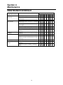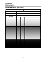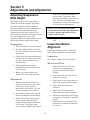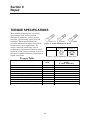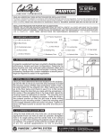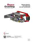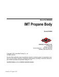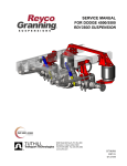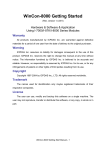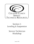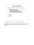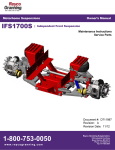
1
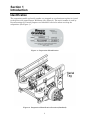
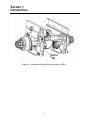
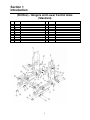
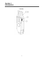
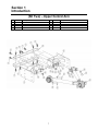
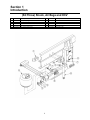
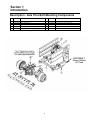
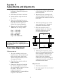
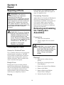
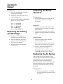
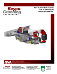
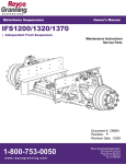
Motorhome Suspensions Owner’s Manual RD2300 | Parallelogram Rear Drive Suspension Maintenance Instructions Service Parts Document #: D707409 Revision: E Revision Date: 4/13 1-800-753-0050 w w w. r eyc o g r anni n g . c om Reyco Granning Suspensions 1205 Industrial Park Drive Mount Vernon, MO 65712 Phone: 417-466-2178 Fax: 417-466-3964 RD2300NR SUSPENSION SERVICE MANUAL Service Notes This Service Manual describes the correct service and repair procedures for the ReycoGranning® RD2300NR Rear Drive Suspension. The information contained in this manual was current at the time of printing and is subject to change without notice or liability. You must follow your company safety procedures when you service or repair the suspension. Be sure you read and understand all the procedures and instructions before you begin work on the suspension. ReycoGranning® uses the following types of notes to give warning of possible safety problems and to give information that will prevent damage to equipment. WARNING A warning indicates procedures that must be followed exactly. Serious personal injury can occur if the procedure is not followed. CAUTION A caution indicates procedures that must be followed exactly. Damage to equipment or suspension components and personal injury can occur if the procedure is not followed. NOTE A note indicates an operation, procedure or instruction that is important for correct service. Some procedures require the use of special tools for safe and correct service. Failure to use these special tools when required can cause personal injury or damage to suspension components. ReycoGranning® Air Suspensions reserves the right to modify the suspension and/or procedures and to change specifications at any time without notice and without incurring obligation. Section 1 Introduction Introduction ReycoGranning® Air Suspensions has developed this service manual to aid in the maintenance of ReycoGranning® ’s rear suspensions. The following table lists the various models and their respective capacities. Model Capacity Axle Cap RD2300NR-T 20,000 lbs 20,000 lbs RD2300NR-T 23,000 lbs 23,000 lbs RD2300NR-WR 23,000 lbs 23,000 lbs Overloading the suspension may result in adverse ride and handling characteristics. 2 Section 1 Introduction Identification The suspension model and serial number are stamped on an aluminum tag that is riveted to the driver side upper Hanger Weldment. (See Figure 2). The serial number is used by ReycoGranning® for control purposes and should be referred to when servicing the suspension. (See Figure 1). Figure 1: Suspension Identification Figure 2: Suspension Identification Location (Standard) 3 Section 1 Introduction Figure 3: Suspension Identification Location (-WR) 4 Section 1 Introduction (Kit One) - Hangers and Lower Control Arms (Standard) Item 1 *21 2 *22 3 4 5 6 7 8 9 Part No. Description 70737301 71027601 70737302 71027602 70736502 70736501 70545001 70545402 71051301 70545301 70251602 Weldment, Hanger (LH) Weldment Hanger (LH) (-WR Only) Weldment, Hanger (RH) Weldment Hanger (RH) (-WR Only) Assy, Lower Arm (RH) Assy, Lower Arm (LH) Wear Spacer, Polyethylene Flange Washer Rey Align Washer, Disk Spring HHB 1 1/8-12 x 7 3/4, Gr. 8, ZN 5 Item Part No. 10 11 12 13 14 15 16 17 18 19 20 166 103003 705456-01 705446-01 700020-01 89422312 89429523 24453-01 2617 188 706260-01 Description LN 1 1/8-12, Gr. C, ZY HFW 3/4 X .812x1.475 X .150N Rey Align Adjust Shaft Assy, Cross Tube, W/ Bushings HHB 1-14 x 7, Gr. 8, ZN LN 1-14, Gr. C, CP FW 1" 1.062x1.75x.10 PL Coiled Spring Pin Plate-Serial No. Pop Rivet 1/8" dia. x .525" long Wear Spacer, Polyethylene Section 1 Introduction 6 Section 1 Introduction (Kit Two) – Upper Control Arm Item Part No. 1 2 3 4 707378-01 707378-02 707377-01 705435-01 Description Weldment, V-Link Mount (LH) Weldment, V-Link Mount (RH) Cross Member V-Link 7 Item Part No. Description 5 6 7 8 2858 8455851 309 308 HHB 5/8-11 X 2 1/4 GR8 SLW 5/8 .651 x 1.250 x .166 ZN FHB ½-13 x 1.25”, Gr. 8, ZN LFN ½-13, Gr. G Zinc Section 1 Introduction (Kit Three) Shock, Air Bags and HCV Item Part No. 1 2 3 4 5 706924-01 8103323 8120378 89415543 707402-01 Description Air Spring Support SLW 1/2 .523x.873x.135 PL N 1/2-13 GR 5 ZP FW ½ .531x1.25x.100 ZN Air Spring (Firestone) 8 Item Part No. 6 7 8 9 10 706206-01 103003 8223831 178 707923-01 Description Shock Absorber HFW ¾ .812 x 1.475 x .150 HHB ¾-16 x 3 ½, Gr. 8 ZN LFN ¾-16 Gr.6 Shock Bracket Section 1 Introduction Description - Axle Thru Bolt Mounting Components Item Part No. Description Item 1 2 3 705429-02 Tube, Inner Spacing ** 705429-03 Boss, Mounting ** 705429-04 HHB 3/4-16 X 6.500 ** 6 7 4 705429-05 FW 3/4 .811 X 1.375 X .104 ** 9 5 705429-06 LN 3/4-16 ** 8 ** Part of Thru Bolt Bushing Kit PN(705429-07) 9 Part No. Description 104098 HFW 7/8 .968 x 1.780 x .160 ZP 100122-P1 LN 7/8-9 UNC Stover GR.C ZP None Customer Supplied Axle 8223552 HHB 7/8-9 X 5, GR.8, ZN Section 2 Troubleshooting Suspension System--General SYMPTOMS POSSIBLE CAUSES Tires wear out quickly or have 1) Tires have incorrect pressure. uneven tire tread wear. Note: Wear pattern will indicate 2) Tires out of balance. possible cause(s). Consult tire 3) Incorrect ride height. manufacturer for guidance. 4) Incorrect rear axle alignment. Vehicle rolls side to side excessively. Vehicle ride is too harsh and/or suspension contacts stops excessively. Vehicle ride is too soft. Suspension does not maintain ride height. REMEDIES 1) Put specified air pressure in tires. 2) Balance or replace tires. 3) Adjust ride height to specified setting. 4) Align rear axle to specified thrust angle. 5) Improper(mismatched) tires 5) Install correct tire and wheel and wheels. combination. 1) Front and/or rear shock 1) Replace shock absorbers as absorbers worn. needed. 2) Shock mounting loose. 2) Check and tighten as required. 3) Shock eye bushings worn. 3) Check and replace as needed. 4) Trailing Arm bushings worn. 4) Inspect and replace as required. 5) Check for air leak including 5) Check height control valve the height control valve. and replace as required. 1) Shock absorbers worn. 1) Replace shock absorbers as needed. 2) Adjust ride height to specified 2) Incorrect ride height. setting. 3) Check wheel loads and correct 3) Vehicle overloaded. as needed. 4) Check air line connections 4) Air spring supply lines and remove obstructions. leaking or obstructed. 5) Check air pressure and 5) Vehicle system air pressure below specification. correct as needed. 6) Jounce bumper in air spring 6) Check and replace air spring worn or broken. as required. 1) Shock absorbers worn. 1) Replace shock absorbers as needed. 2) Incorrect ride height. 2) Adjust ride height to specified setting. 1) Air leak. 1) Check connections with soapy water solution and repair or replace as needed. 2) Internal leak in height control 2) Check height control valve valve. and replace as required. 3) Height control valve linkage 3) Check and tighten linkage as loose. needed. 4) Air spring chafed or worn. 4) Check air spring and replace as needed. 10 Section 3 Inspection General Inspection Checking the Trailing Arm Bushings for Wear Perform a thorough visual inspection of the suspension to ensure proper assembly and to identify broken parts and loose fasteners each time the vehicle suspension is serviced. Do the following during an inspection. Wheel Alignment - Follow the guidelines in Section 5 for wheel alignment inspection intervals. Check wheel alignment if excessive steering effort, vehicle wander, or abnormal tire wear is evident. Fasteners - Check that all the fasteners are tightened to the proper tightening torque. Use a calibrated torque wrench to check torque. Wear and Damage - Inspect components of the suspension for wear and damage. Look for bent or broken components. Replace all worn or damaged components. NOTE: ReycoGranning® recommends the use of a maintenance pit or full vehicle lift during the inspection of components. Preparation 1. Chock the front wheels to prevent vehicle movement. 2. Raise the rear of the vehicle until the wheels are off the ground. Support raised vehicle with safety stands. Do not place jacks or safety stands under the Trailing Arms to support the vehicle. WARNING: Never work under a vehicle supported by only a jack. Jacks can slip or fall over and cause serious personal injury. Always use safety stands. Operation - Check that all components move freely through the complete turning arc. 3. Remove the tires. ReycoGranning® CAUTION: recommends replacing any damaged or out-of-specification components. Reconditioning or field repairs of major rear suspension components is not allowed. Inspection 1. Inspect rubber bushings for large splits, tears, and major wear. Replace bushings as needed. 2. Check that the Trailing Arm mounting bolts are tight. The recommended torque is 210-240 ft-lb. See Torque Table. Note: Refer to Section 1 for identification of components. 11 Section 3 Inspection Check for air line and fitting leaks with soapy water solution. Checking the Shock Absorber 3. Check to see that there is minimum of 1 inch clearance around the circumference of the air spring while it is energized with air. NOTE: ReycoGranning® recommends the use of a maintenance pit or full vehicle lift during the inspection of components. 4. Check the air spring piston for build up of foreign material. Remove any foreign material that is present. Preparation 1. Set the parking brake and block the drive wheels to prevent vehicle movement. Height Control Valve Inspection 1. Check the height control valve and linkage for damage. Replace components as needed. Inspection 1. Check shock absorber for oil leakage, bent components, missing or broken components, excessive corrosion, or worn bushings. Replace shock if any of the above items is present. 2. Measure the ride height of the suspension. The ride height should be 7.00 inches. It is measured at the axle centerline and is the distance from the bottom of the chassis frame rail to the center of the wheel. Checking the Air Spring and Height Control Valve 3. The actuation arm of the height control valve should be horizontal at ride height. See section 5 for adjusting to correct ride height. Preparation 1. Set the parking brake and block the drive wheels to prevent vehicle movement. 2. Refer to Firestone Preventative Maintenance Checklist for additional air spring information. Air Spring Inspection 1. Check the outside diameter of the air spring for irregular wear or heat checking. 2. Check air lines to make sure contact does not exist between the air lines and the outside diameter of the air spring. Re-secure air lines to prevent contact as needed. 12 Section 3 Inspection Checking the V-Link Bolts and Bushings Preparation 1. Chock the front wheels to prevent vehicle movement. 2. Raise the rear of the vehicle until the wheels are off the ground. Support raised vehicle with safety stands. Do not place jacks or safety stands under the Trailing Arms to support the vehicle. WARNING: Never work under a vehicle supported by only a jack. Jacks can slip or fall over and cause serious personal injury. Always use safety stands. Inspection 1. Inspect rubber bushings for large splits, tears, and major wear. Replace bushings as needed. Check that the V-Link to V-Link Mount Weldment mounting bolts are tight. The recommended torque is 150-180 ft-lb. See Torque Table Check that the V-Link Axle Mounting bolts are tight. The recommended torque is 400-495 ft-lb. See Torque Table 13 Section 4 Maintenance MAINTENANCE SCHEDULE GENERAL MAINTENANCE Trailing Arm Bushings SERVICE TO BE PERFORMED Check bolt torque. Inspect for contact between control arm and mount. Inspect for bushing wear. Air Springs Inspect for proper clearance (1” minimum all around). Check upper mount nut and lower mount bolt torque. Inspect for signs of chafing or wear. Check for air line fitting torque. Inspect for air leaks using soapy water solution. Height Control Valve Inspect for signs of bending, binding, or slippage. Linkage Shock Absorbers Check stud mount and lock nut torque. Inspect shocks for signs of fluid leak, broken eye ends, loose fasteners, or worn bushings. Rear Alignment Inspect (after first 1000-3000 miles) Air Fittings and Air Inspect for air leaks using soapy water Lines solution. Inspect for signs of chafing, cracking, or wear. MILEAGE IN THOUSANDS 12 24 36 48 60 72 84 96 X X X X1 X X X X X X X X1 X X X X X X X X X1 X X X X X X X X X X1 X X X X X X X X1 X X X X X X X X X1 X X1 X X X1 X X X 1. Continue to perform specified maintenance every 12,000 miles or at previous interval. 14 X X X X X X Section 4 Maintenance MAINTENANCE RECORD Name of Owner Address of Owner Date of Purchase Name and Address of Dealer Model of Vehicle Vehicle Identification Number Suspension Model Number: Suspension Serial Number: RD2300NR Inspection and Maintenance Date Mileage Item 15 Service Performed Section 5 Adjustments and Alignments link. If the measured distance is greater than 7.00 inches, then decrease the length of the vertical link. Wait 30 seconds for the suspension to settle after adjusting to verify correct adjustment. Adjusting Suspension Ride Height The height control valve and linkage should be checked regularly for proper clearance, operation and adjustment. The ride height of the rear suspension is the distance from the bottom of the chassis frame rail to the center of the axle. Properly adjusted ride height results in correct suspension travel and alignment. The ride height should not be adjusted to adjust chassis rake angle. NOTE: The horizontal link must remain horizontal during adjustment to ensure proper operation of the height control valve. 4. Tighten the clamp on the vertical link. Inspection Before Alignment Preparation 1. Park the vehicle on a level surface. 2. Set the parking brake and block the drive wheels to prevent vehicle movement. Check the following before conducting front wheel alignment measurements. 3. Check that the front suspension is adjusted to the correct ride height per the vehicle manufacturers specifications. Inspection See “General Inspection” in Section 3. Wheels and Tires 4. Check height control valve plumbing to ensure there are not any air leaks. 1. Check that the rear tires are inflated to the appropriate pressure based on the wheel loading. 5. Make sure shock mounts are mounted securely and not bent. 2. Check that the rear tires are the same size and type. Adjustment 3. Check that all the wheel nuts are tightened to the specified torque. 1. Measure the distance from the bottom of the frame to the center of the axle. If the distance measured is not within 7.00±.25 inches, then adjust as follows. 4. Check that the wheels are balanced. 5. Check that all fasteners are tightened to the specified torque. 2. Loosen the clamp on the vertical link of the height control linkage. 6. Check the suspension ride height and adjust as needed to specified height. 3. Adjust the length of the vertical link to achieve specified ride height. If the measured distance is less than 7.00 inches, then increase the length of the vertical 7. Check that all connection joints between the suspension and axle are secure. 16 Section 5 Adjustments and Alignments 8. Check for worn suspension bushings or damaged suspension components. 4. The cross bar should be positioned as far forward of the drive axle as room will permit. 9. Check that the frame is not bent. 5. Beginning on the passenger side, measure from the bar stock to the center line of the rear drive axle on both sides. 10. Loosen the Rey-align nut but do not remove. 11. Rotate the adjusting fastener to move the rear axle fore and aft on each side. Continue until you achieve the correct alignment. 6. If the measurements, X1 and X2, vary more than 1/8”, alignment adjustment should be made. 12. Retorque the Pivot Bolt to 9501050 ft-lb. See Torque Table. 7. Once the rear drive axle is properly aligned, the front axle should be aligned as per the recommended procedure. Step 1: 150 ft-lb Step 2: 250 ft-lb Step 3: 400 ft-lb Step 4: 650 ft-lb Step 5: 950-1050 ft-lb X1 NOTE: Total vehicle alignment is recommended when aligning the rear suspension. X2 Rear Axle Alignment Figure 4. Alignment measurements. 8. Following the alignment of both axles, it is recommended that it be driven through a short series of turns and then returned to the shop to have the alignment rechecked, after again freeing all suspension joints by moving back and forth several times. Measurement 1. Place the unloaded vehicle on a level floor area. Move it back and forth several times, slowly and without using the brakes, to free all suspension joints. 2. Chock the front wheels with the brakes released. Adjustment 3. Clamp an 8 foot piece of straight bar stock or angle iron securely after positioning it squarely across the frame. The use of a carpenter’s square is recommended to be certain the bar is square to the frame. 1. Chock the front wheels. 2. Securely support the rear frame of the vehicle. 17 Section 5 Adjustments and Alignments NOTE: +/- 3/8” Total adjustment is available. (3/16” / Side x 2 adjustment points.) WARNING: Never work under a vehicle supported by only a jack. Jacks can slip or fall over and cause serious personal injury. Always use safety stands. 6. Retorque the Pivot Bolt to 9501050 ft-lb. See Torque Table. Step 1: 150 ft-lb Step 2: 250 ft-lb Step 3: 400 ft-lb Step 4: 650 ft-lb Step 5: 950-1050 ft-lb 3. Exhaust the air from the air springs to remove the load to the Trailing Arm. 4. Loosen the Rey-align nut but do not remove. 5. Rotate the adjusting fastener to move the rear axle fore and aft on each side. Continue until you achieve the correct alignment. 18 Section 6 Repair Parts must be dried immediately after cleaning. Dry parts with clean paper or rags, or compressed air. Repairing of Parts WARNING: The repair or reconditioning of rear suspension components is not allowed. ReycoGranning® recommends replacing damaged or worn components. Several major components are heat treated and tempered. The components cannot be bent, welded, heated or repaired in any way without reducing the strength or life of the component and voiding the warranty. Preventing Corrosion Apply light oil to cleaned and dried parts that are not damaged and are to be immediately assembled. If the parts are to be stored, apply a good corrosion preventative to all surfaces and place them inside special paper or containers that prevent corrosion. Removing and Installing the Trailing Arm Assemblies WARNING: If you use cleaning solvents, hot solution tanks or alkaline solutions incorrectly, serious personal injury can occur. To prevent injury, follow the instructions supplied by the manufacturer. Do NOT use gasoline to clean parts. Gasoline can explode. Preparation 1. Chock the front wheels. 2. Firmly support the rear vehicle frame. WARNING: Never work under a vehicle supported by only a jack. Jacks can slip or fall over and cause serious personal injury. Always use safety stands. Cleaning the Parts Ground or Polished Parts Use a cleaning solvent to clean ground or polished parts and surfaces. Do NOT clean ground or polished parts with hot solution tank or with water, steam or alkaline solutions. These solutions will cause corrosion of the parts. Removal 1. Exhaust the air from the air spring. Rough Parts 2. Detach the air spring from the Cross Member. Rough parts can be cleaned with the ground and polished parts. Rough parts also can be cleaned in hot solution tanks with a weak alkaline solution. Parts should remain in the hot solution tanks until they are completely cleaned. 3. Remove the Lower Cross Member 4. Remove Axle Bolts. 5. Remove Shocks and Height Control Valve Linkages. 6. Loosen the pivot bolt nut. Drying 19 Section 6 Repair Installation 1. Slide the trailing arm assembly into the pivot hanger. Replacing the Shock Absorber 2. Insert the pivot bolt with all reyalign components. Preparation 3. Torque the Pivot Bolt to 950-1050 ft-lb. See Torque Table. 1. Set the parking brake and block the front wheels to prevent vehicle movement. Step 1: 150 ft-lb Step 2: 250 ft-lb Step 3: 400 ft-lb Step 4: 650 ft-lb Step 5: 950-1050 ft-lb Removal 1. Loosen and remove the upper shock absorber mount bolt from the upper Shock Mount. 2. Loosen and remove the lower shock absorber mount bolt from the trailing Arm. Replacing the Trailing Arm Bushings 1. Remove the Trailing Arm assembly as described above. 2. Push the bushing out using a properly sized bushing press. 3. Push in new bushing. 4. Reinstall as per the previous instructions. Installation 1. Install the upper shock absorber Fasten using the bolt. 2. Install the lower shock absorber bolt loosely to the trailing arm assembly. 3. Raise or lower the suspension to approximately ride height. 4. Torque both mount fasteners to 90110 ft-lb. See the Torque Table. Replacing the Air Spring When replacing the air spring be sure that the correct replacement air spring is installed. The use of a substitute air spring that is not recommended by ReycoGranning® may cause unequal load sharing between the air springs which may be detrimental to vehicle ride and handling. Preparation 1. Set the parking brake and block the front wheels to prevent vehicle movement. 20 Section 6 Repair 2. Firmly support the rear of the vehicle frame. Replacing the Height Control Valve WARNING: Never work under a vehicle supported by only a jack. Jacks can slip or fall over and cause serious personal injury. Always use safety stands. Preparation 1. Set the parking brake and block the front wheels to prevent vehicle movement. 3. Deflate the air springs. 2. Firmly support the rear vehicle frame. Removal 1. Disconnect the air line at the air spring and remove the connection fitting. WARNING: Never work under a vehicle supported by only a jack. Jacks can slip or fall over and cause serious personal injury. Always use safety stands. 2. Remove the bolts that secure the air spring to the lower crossmember assembly. 3. Remove the nuts and washers from the upper frame rail mount. 3. Deflate the air springs. 4. Remove the air spring. Removal Installation 1. Mark air line connections for reassembly. Disconnect the air lines from the HCV. If any other plumbing fixtures are connected to the HCV, mark them for reassembly. 1. Assemble the nuts and washers that connect the air spring to the frame rail. Tighten the nuts to appropriate torque per chassis MFG requirement. 2. Disconnect the vertical link from the trailing arm. 2. Assemble the air spring to the crossmember assembly. Tighten the bolts to 20-30 ft-lb. See Torque Table. 3. Remove the mounting bolts, nuts, washers, and HCV from the Frame Rail. 3. Install the connection fitting into the air spring. Use Permatex or equivalent thread sealant. 4. Remove any other plumbing fixtures from the HCV. 4. Connect the air line to the air spring. Installation 5. Lower the vehicle frame and inflate the air springs. 1. Assemble the actuation arm and the vertical link of the replacement HCV the same as the 6. Check the air fittings for leaks. 21 Section 6 Repair removed HCV. or lowered to relive excessive pressure on the V-Link. 2. Assemble any other plumbing fixtures to the HCV as marked for re-connection. 3. Remove both inner bolts on the VLink so that it is still supported by the two outer V-Link bolts. 3. Mount the replacement HCV to the frame rail with bolts, nuts, and washers. Tighten the nuts to 6080 in-lb. See Torque Table. 4. Make sure the V-Link assembly is fully supported before removing the final two bolts holding it place. 4. Reconnect air lines and check for proper operation and leaks. WARNING: V-link is very heavy. 5. Check and adjust ride height per Adjusting Suspension Ride Height Section. Replacing the V-Link 5. Remove the V-Link Assembly. Installation Preparation 1. Replace the V-Link in the same order in which it was removed. Torque the 4 bolts holding the Vlink to the Cross member to 150180 ft-lb. See Torque Table. 1. Set the parking brake and block the front wheels to prevent vehicle movement. 2. Firmly support the rear vehicle frame. 2. WARNING: Never work under a vehicle supported by only a jack. Jacks can slip or fall over and cause serious personal injury. Always use safety stands. Reconnect the Axle to the V-Link. Be sure to use the proper spacers to maintain the desired Pinion Angle, and then torque the nut to 400-495 ft-lb. See Torque Table. 3. Relive any support holding the axle up allowing it to float. 4. Re-inflate the airbags so that the Bus can be lowered 3. Deflate the air springs. 4. Support the rear axle to relieve any pressure being applied to the V-link 5. Check and adjust ride height per Adjusting Suspension Ride Height Section. Removal 1. Disconnect the V-Link from the axle and remove the bolts and pinion angle spacers. 2. If the bolts are not easily removed the axle needs to be either raised 22 Section 6 Repair TORQUE SPECIFICATIONS Most threaded fasteners are covered by specifications that define required mechanical properties, such as tensile strength, yield strength, proof load, and hardness. These specifications are carefully considered in initial selection of Figure 5: Grade Markings on Bolts fasteners for a given application. To Grade Lock Nut Lock Nut: assure continued satisfactory vehicle Grade C, G Grade B, F performance, replacement fasteners used Identification should be of the correct strength, as well as the correct nominal diameter, thread pitch, 6 Dots 3 Dots length, and finish. Figure 6: Grade Markings on Lock Nuts Torque Table APPLICATIONS Spring Beam Pivot Nut Upper Shock Absorber Mounting Bolts Lower Shock Absorber Mounting Bolts Air Spring Mount Nut Lower Air Spring Mounting Nut Height Control Linkage Stud Mount V-Link to Cross Member Bolt V-Link to Axle Axle Thru Bolt (For Main Axle Bushing) Air Spring Cross member Mounting Bolts FASTENER SIZE 1-1/8”-12 Gr. C 3/4”-10 Gr. 8 3/4”-16 Gr. 8 1/2”-13 Gr. 8 1/2”-13 Gr. 5 5/16”-18 Gr. 2 5/8”-11 Gr8 7/8”-9 Gr8 3/4”-16 Gr8 3/4”-10 Gr. 8 23 TORQUE SPECIFICATION (ft-lb) (CLEAN AND DRY) 950-1050 90-110 90-110 30-40 20-30 8-12 150-180 400-495 210-240 600-750 IS0 9001:2008 Certified 1-800-753-0050 w w w.r e yc og r a nni n g . c o m Mount Vernon 1205 Industrial Park Drive Mount Vernon,MO 65712 (800) 753-0050,Fax (417) 466-3964