1
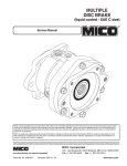
t
49B CALIPER BRAKE TECHNICAL BULLETIN
AND SUPPLEMENT TO SERVICE MANUAL
This document consists of MICO instructions that apply to
the Eskridge 49B Caliper Brake.
CONTENTS
81-600-001 General Guidelines to install Hydraulic Brake Components .. 2
81-950-016 Burnishing Procedures ............................................................... 3
81-950-016 Reduce Exposure to Non-Asbestos Fiber ................................. 4
81-515-007 Spring Apply Sliding Caliper Disc Brakes ................................. 5
81-515-008 Hydraulic Apply Sliding Caliper Disc Brakes ............................ 9
81-515-009 Mechanical Sliding Caliper Disc Brakes ................................. 12
THIS TECHNICAL BULLETIN IS EFFECTIVE
FROM: .......... S/N 57755, SEPT. 1998
TO: ............... CURRENT
REF: .............. TB49B-MICO-AA
www.comoso.com
General Guidelines for installing Hydraulic Brake Components
81-600-001 General Guidelines for installing Hydraulic Brake
How to Mount
Components
To properly mount components and brake lines to withstand the
MICO Hydraulic Brake Components are precision built devices
and must be treated as such. The following guidelines must be
followed at the time of installation to ensure optimum performance.
Where to Mount
To properly locate the brake component or brake line, you must. . .
1. Make it convenient for operator.
2. Use the shortest and most protected route. Protect
components from road salts and general debris.
3. Avoid exposing components and lines in wheel
compartments.
4. Avoid mounting near engine, exhaust lines, muffler or
anywhere that heat may be generated. NOTE: Excessive
heat transferred to brake fluid may result in damage to
lines or seals.
5. Mount units that have to be bled lower than master cylinder
and with bleeder screws on top to facilitate bleeding.
Internal Heat - Cause, Effect, Solution
It is possible for heat to come from within the system itself as in
the case of heat generated by the friction of lining to drum when
braking. This heat can cause the fluid to expand. If the fluid is
then held captive, subsequent cooling and contracting can cause
a pressure drop.
MICO Hydraulic Locking Devices that include a pressure
accumulator are designed to dampen these fluctuations of
pressure and to absorb the increase in pressure within its
operating range.
Cleanliness
It is impossible to overemphasize the importance of cleanliness
during installation. All lines, fittings and adjacent areas must be
cleaned of dirt or road residue before any lines or fittings are
disconnected. Special care must be taken so dirt and road
residue are not allowed to enter the hydraulic brake system.
This can contaminate the system and interfere with the proper
operation of the brakes and other hydraulic components.
Always. . .
1. Use good, clean, quality fluid. Improper or contaminated
brake fluid may cause gummy deposits and softening
and swelling of other rubber seals in the entire brake
system. Such a condition must be corrected immediately.
a. Use brake fluid which conforms to SAE Spec. No.
J1703 or DOT 3 or 4 if the product is used with a
system utilizing automotive brake fluid.
b. Refer to vehicle manufacturer for fluid specification if
product is used with:
1. Mineral based hydraulic oil.
2. Phosphate ester base fluid.
3. Water/glycol fluid.
4. Water-in-oil emulsion fluid.
5. DOT 5 or silicone fluid.
2. Be sure fittings and seats are clean before making
connections. Do not use sealants, tapes, teflon or cement
compounds on any connections or fittings. These sealants
or compounds can contaminate the hydraulic brake
system and interfere with the operation of brake system
components.
3. Clean top of master cylinder before removing filler cap.
most severe vibration conditions, always. . .
1. Follow the procedures outlined in Vehicle Manufacturer’s
Service Manual or SAE Standards when making new
connections or adding to existing brake system. Use only
steel brake tubing conforming to SAE specifications.
2. Use the proper size bolt for the hole and secure with a
steel lock washer whenever possible.
3. Secure tubing to frame with proper size tube clamps to
avoid possible fractures or fittings loosening and leaking.
4. Use good, factory flared lengths of steel tubing. Hand
made flares, when used, must be double flared. Any
flash or loose particles must be moved.
5. Use flexible brake line between frame and body.
6. Use grommets or some other means to protect brake
lines that pass through the frame or firewall.
7. Make sure fittings and connections are in good condition
and tightened to proper torque values as specified in
the installation and service instructions.
Importance of Bleeding
The hydraulic brake system must be bled whenever any line has
been disconnected. Air trapped in the system can cause spongy
and inadequate brakes. There are two methods of bleeding
hydraulic systems, pressure bleeding and manual bleeding. Both
methods are acceptable and adequate but pressure bleeding is
recommended if the equipment is available. Follow bleeding
instructions as specified by vehicle manufacturer.
To properly bleed the system. . .
1. Be certain all fittings are tight to avoid leaking.
2. Depress pedal and open up bleeder screws to allow air
to escape. Air will always seek the highest level.
3. Retighten bleeder screws and allow pedal to return.
4. Repeat cycle until pedal is firm.
5. Make several static brake applications and then repeat
cycle once more.
Leak in the System
Even the smallest leak in a brake system will adversely affect
the system. A leak may eventually deplete the reserve supply
and reduce braking pressure. To help prevent leaking. . .
1. Check connections during bleeding and static brake
processes to be sure they are tight.
2. Always reinstall new hoses, lines and fittings if they look
the least bit questionable.
3. Brake hoses, brake lines, MICO locking device, brake
components, cylinders, and all fittings must be routinely
inspected for leaks, damage or wear. Adequate fluid
levels must be maintained. In the event of any loss of
fluid, the brake system must be carefully inspected for
leaks.
MICO has made every attempt to present accurate information in catalogs, brochures and other printed material. MICO can accept no responsibility for errors from unintentional oversights that may exist. Due to a continuous program of product improvement, both materials and specifications are subject to change without notice or obligation.
MICO is a registered trademark of MICO, Incorporated. MICO is registered in the U.S. Patent and Trademark Office as well as in Canada, Great Britain, South Korea and Australia.
MICO, Incorporated
MICO West Division
1911 Lee Boulevard (Zip Code 56003-2507)
P.O. Box 8118 / North Mankato, MN U.S.A. 56002-8118
( (507) 625-6426 Facsimile (507) 625-3212
701 East Francis Street (Zip Code 91761-5514)
P.O. Box 9058 / Ontario, CA U.S.A. 91762-9058
( (909) 947-4077 Facsimile (909) 947-6054
Form No. 81-600-001
Revised 5/97
Printed in U.S.A.
www.comoso.com
Burnishing Procedures
81-950-016
BURNISHING
PROCEDURES
for MICO
Caliper Disc
Brakes
81-950-016
Burnishing
Procedures
FOR
MICO CALIPER
DISC
BRAKES
TECHNICAL NOTICE
Maximum torque will be achieved only after the
brake has been properly burnished. Actual customer
testing will be required to determine final acceptance
and approval of brake system components.
MICO recommends the following SAE burnishing procedures be performed immediately following the installation and adjustment of the brake. These “SAE
recommended practices” (J360; paragraph 7.3 for
parking brakes and J786a; paragraph 5.5 for service
brakes) are intended to be used as guidelines only.
Contact the vehicle (or equipment) manufacturer for
specific recommendations.
PARKING BRAKE: Make 10 stops from 10 mph
(45 m/s) at 3 ft/s2 (0.9 m/s2). Space the stops a minimum of 2.5 miles (4000 m) apart and operate the
vehicle at 20 mph (9 m/s) between stops.
SERVICE BRAKE: Make at least 200 “Brake Snubs”,
not less than 50 in a series, from 40 to 20 mph (64 to
32 km/hr.) at 10 ft/s2 (3 m/s2) in normal gear range.
[A “Brake Snub” is the act of retarding a motor vehicle
between two positive speed values by the use of a
brake system.]
Accelerate to 40 mph at moderate acceleration after
each “snub” and drive 40 mph (64 km/hr) between
snubs.
At every 25th application (minimum), make a full stop
from 40 mph (46 km/hr.).
APPLICATION INTERVALS:
• For light trucks and buses [6,000-10,000 lb.
(2,700-4,500kg) GVW]: 1.0 mile (1.6 km)
• For truck, bus, and combination of vehicles [over
10,000 lb. (4,500 kg) GVW]: 1.5 miles (2.4 km)
NOTE: Other burnish procedures which produce
similar braking conditions and performance characteristics are permissible.
After burnishing, adjust the parking brake and actuation
system in accordance with MICO specifications (or the
appropriate manufacturer’s specifications for components of the actuation system not supplied by MICO).
Immediately following any dynamic stop resulting from
the application of the parking brake, the brake and disc
must be inspected for any unusual wear or conditions
and then adjusted in accordance with MICO specifications.
Recommended Disc Material
High quality brake discs should be used in
conjunction with MICO Caliper Disc Brakes.
Depending on strength and performance
requirements, low to medium carbon steel is
generally recommended. Fabrication procedures are as follows:
1. Flame cut or machine to required
outside diameter with inside diameter
machined to size.
2. Stress relieve after all machining
operations.
3. Blanchard ground to a surface finish
of 54 Ra to 72 Ra with a visible crosshatch pattern.
4. Surfaces to be parallel within .05 mm (.002").
5. Surfaces to be flat within .13 mm (.005").
MICO could not possibly know of and give advice with respect to all conceivable applications in which this product may be used and the possible hazards and/or
results of each application. MICO has not undertaken any such wide evaluation. Therefore, anyone who uses an application which is not recommended by the
manufacturer, first must completely satisfy himself that a danger will not be created by the application selected, or by the particular model of our product that is
selected for the application.
MICO has made every attempt to present accurate information in catalogs, brochures and other printed material. MICO can accept no responsibility for errors from
unintentional oversights that may exist. Due to a continuous program of product improvement, both materials and specifications are subject to change without notice or obligation.
MICO is a registered trademark of MICO, Incorporated. MICO is registered in the U.S. Patent and Trademark Office as well as in Canada, Great Britain, South Korea, and Australia.
MICO, Incorporated
MICO West Division
1911 Lee Boulevard (Zip Code 56003-2507)
P.O. Box 8118 / North Mankato, MN U.S.A. 56002-8118
( 507.625.6426 Facsimile 507.625.3212
701 East Francis Street (Zip Code 91761-5514)
P.O. Box 9058 / Ontario, CA U.S.A. 91762-9058
( 909.947.4077 Facsimile 909.947.6054
Form No. 81-950-016
Revised 10/14/98
www.comoso.com
Printed in U.S.A.
81-950-016 Recommended Procedures to Reduce ExpoRecommended Brake Service Procedures
sure to Non-Asbestos
Fiber
81-950-016
Burnishing Procedures
to Reduce Exposure to Non-Asbestos Fiber
for MICO Caliper Disc Brakes
TECHNICAL NOTICE
FOR ALL MICO NON-ASBESTOS BRAKE LININGS
Recently manufactured brake linings no longer contain
asbestos fibers. In place of asbestos, these linings
contain a variety of ingredients, including glass fibers,
mineral wool, aramid fibers, ceramic fibers, and
carbon fibers. At present, OSHA does not specifically
regulate these non-asbestos fibers, except as nuisance dust. Medical experts do not agree about the
potential long-term risks from working with and
1. Whenever possible, work on brakes in a separate
area away from other operations.
2. Always wear a respirator approved by NIOSH or
MSHA during all brake service procedures. Wear
the respirator from removal of the wheels through
assembly.
3. NEVER use compressed air or dry brushing to
clean brake parts or assemblies. OSHA recommends that you use cylinders that enclose the
brake. These cylinders have vacuums with high
efficiency (HEPA) filters and worker’s arm sleeves.
But, if such equipment is not available, carefully
clean parts and assemblies in the open air.
4. During disassembly, carefully place all parts on the
floor to avoid getting dust into the air. Use an
industrial vacuum cleaner with a HEPA filter system
to clean dust from the brake drums, backing plates
and other brake parts. After using the vacuum,
remove any remaining dust with a rag soaked in
water and wrung until nearly dry.
5. Grinding or machining brake linings. If you must
inhaling non-asbestos fibers. Some experts
nonetheless think that long-term exposure to some
non-asbestos fibers may cause diseases of the lung,
including pneumoconiosis, fibrosis and cancer. Therefore, MICO recommends that workers use caution to
avoid creating and breathing dust when working on
brakes that contain non-asbestos fibers.
grind or machine brake linings, take additional
precautions because contact with fiber dust is
higher during these operations. In addition to
wearing an approved respirator, do such work in
an area with exhaust ventilation.
6. Cleaning the work area. NEVER use compressed
air or dry sweeping to clean the work area. Use an
industrial vacuum with a HEPA filter and rags
soaked in water and wrung until nearly dry. Dispose of used rags with care to avoid getting dust
into the air. Use an approved respirator when
emptying vacuum cleaners and handling used
rags.
7. Worker clean-up. Wash your hands before eating,
drinking or smoking. Do not wear your work
clothes home. Vacuum your work clothes after
use and then launder them separately, without
shaking, to prevent fiber dust from getting into the
air.
8. Material safety data sheets on this product, as
required by OSHA, are available from MICO.
MICO could not possibly know of and give advice with respect to all conceivable applications in which this product may be used and the possible hazards and/or
results of each application. MICO has not undertaken any such wide evaluation. Therefore, anyone who uses an application which is not recommended by the
manufacturer, first must completely satisfy himself that a danger will not be created by the application selected, or by the particular model of our product that is
selected for the application.
MICO has made every attempt to present accurate information in catalogs, brochures and other printed material. MICO can accept no responsibility for errors from
unintentional oversights that may exist. Due to a continuous program of product improvement, both materials and specifications are subject to change without notice or obligation.
MICO is a registered trademark of MICO, Incorporated. MICO is registered in the U.S. Patent and Trademark Office as well as in Canada, Great Britain, South Korea and Australia.
MICO, Incorporated
MICO West Division
1911 Lee Boulevard (Zip Code 56003-2507)
P.O. Box 8118 / North Mankato, MN U.S.A. 56002-8118
( 507.625.6426 Facsimile 507.625.3212
701 East Francis Street (Zip Code 91761-5514)
P.O. Box 9058 / Ontario, CA U.S.A. 91762-9058
( 909.947.4077 Facsimile 909.947.6054
Form No. 81-950-016
Revised 10/14/98
Printed in U.S.A.
www.comoso.com
Installation and Service Instructions
APPLY
81-515-007 SpringSPRING
Apply Sliding
Caliper Disc Brakes
Sliding Caliper Disc Brakes
515 SERIES
TABLE 1
Model
Lining
Seal
Repair
Model
Lining
Seal
Number
Kit
Kit
Kit Number
Kit
Kit
02-515-001 (BF)
20-060-082
02-500-037
02-500-192
* 02-515-152 (HO)
20-060-082
02-500-095
02-515-002 (HO)
20-060-082
02-500-036
02-500-187
02-515-154 (HO)
20-060-082
02-500-036
02-515-003 (BF)
20-060-082
02-500-037
02-500-193
* 03-515-003 (BF)
20-060-082
02-500-137
02-515-004 (HO)
20-060-082
02-500-036
02-500-186
* 03-515-004 (HO)
20-060-082
02-500-095
02-515-005 (BF)
20-060-082
02-500-037
02-500-194
* 03-515-005 (BF)
20-060-082
02-500-137
02-515-006 (HO)
20-060-082
02-500-036
02-500-188
* 03-515-006 (HO)
20-060-082
02-500-095
02-515-007 (BF)
20-060-082
02-500-037
02-500-195
* 03-515-008 (HO)
20-060-082
02-500-095
02-515-008 (HO)
20-060-082
02-500-036
02-500-190
* 03-515-013 (BF)
20-060-082
02-500-139
02-515-012 (HO)
20-060-082
02-500-036
02-500-189
* 03-515-014 (HO)
20-060-082
02-500-095
02-515-018 (HO)
20-060-036
02-500-036
02-500-188
* 03-515-016 (HO)
20-060-082
02-500-095
02-515-020 (HO)
20-060-082
02-500-036
02-500-190
* 03-515-018 (HO)
20-060-082
02-500-095
02-515-022 (HO)
20-060-082
02-500-077
None
* 03-515-023 (BF)
20-060-082
02-500-137
02-515-024 (HO)
20-060-082
02-500-077
02-500-197
* 03-515-028 (HO)
20-060-082
02-500-095
02-515-028 (HO)
20-060-082
02-500-077
None
03-515-034 (HO)
20-060-082
02-500-036
02-515-038 (HO)
20-060-082
02-500-036
02-500-191
03-515-036 (HO)
20-060-082
02-500-036
02-515-044 (HO)
20-060-082
02-500-036
02-500-216
03-515-038 (HO)
20-060-082
02-500-095
02-515-119 (BF)
20-060-082
02-500-037
02-500-196
* 03-515-104 (HO)
20-060-082
02-500-208
BF = Brake Fluid
HO = Mineral Base Hydraulic Oil
* With swivel inlet fitting (See swivel fitting block drawing, Figure 5, on page three).
·Belleville Springs are pre-greased, DO NOT remove grease from springs (See GREASE NOTE in Figure 4).
Repair
Kit ·
02-500-199
02-500-186
02-500-205
02-500-200
02-500-204
02-500-201
02-500-202
02-500-205
02-500-200
02-500-201
02-500-202
02-500-205
02-500-202
02-500-200
02-500-186
02-500-203
02-500-209
READ GENERAL INSTALLATION GUIDELINES SHEET (81-600-001) BEFORE PROCEEDING
MICO Disc Brake Linings do not contain asbestos. Brake lining compounds do, however, contain elements that
may become airborne during the life of the lining. To prevent any health problems associated with lining dust, we
suggest ventilators be installed as needed on enclosed or stationary equipment. A Material Safety Data Sheet is
available upon request.
When installing these MICO 515 Series Brakes, it is of
utmost importance to maintain parallelism between
mounting bolts and that caliper be centered evenly and
squarely over disc. This will prevent binding of caliper
and ensure even lining to disc contact.
These MICO 515 Series Brakes are designed to be
used with a disc thickness of 12.7 mm (.50"). For other
disc thicknesses, contact MICO, Inc.
DISC CENTERLINE TO
MOUNTING HOLE DIMENSION
millimeters
inches
FIGURE 1
DISC
DIA.
152.4 mm (6")
203.2 mm (8")
254.0 mm (10")
304.8 mm (12")
355.6 mm (14")
406.4 mm (16")
457.2 mm (18")
508.0 mm (20")
"A" DIM.
85.9 mm (3.38")
111.3 mm (4.38")
136.7 mm (5.38")
162.1 mm (6.38")
187.5 mm (7.38")
212.9 mm (8.38")
238.3 mm (9.38")
263.7 mm (10.38")
TABLE 2
For disc diameters greater than 508.0 mm,
add 9.7 mm (20", add .38") to disc radius to
obtain "A" dimension.
www.comoso.com
FIGURE 2
MOUNTING PROCEDURE
1. Using Figure 1 and Table 2, determine “A” dimension and locate caliper mounting holes.
2. Distance from mounting surface to head of
mounting bolt is 82.6 mm (3.25") regardless of disc
thickness.
3. Mount brake on disc and bolt securely to vehicle or
machine using grade 5 or better mounting bolts or
pins.
NOTE: Due to the extreme pressure created
by the belleville springs (11), the procedure shown in Figure 3 is needed to
disassemble brake module housing (7).
HYDRAULIC CONNECTION &
ADJUSTMENT PROCEDURE
(Refer to Figure 4)
Port Size: #4 SAE O-ring Boss
1. Install hydraulic line, leaving tube nut slightly loose
to allow turning adjustment of brake module.
NOTE: The adjusting procedure may be simplified if a swivel fitting is used. (See swivel fitting
block chart, Table 3.)
2. Bleed system using bleeder screw (8) at highest
point making sure all air is eliminated.
FIGURE 3
During the bleeding process for these MICO 515 Series
Brakes, hydraulic pressure should not exceed 13.8 bar
(200 psi).
3. Apply hydraulic pressure and check for leaks.
4. Apply rated hydraulic pressure.
5. Thread in brake module until a total clearance of
approximately .30 mm (.012") is obtained between
disc and linings. Use a spanner wrench if necessary.
6. Tighten set screw (16) and release hydraulic pressure.
7. Tighten hydraulic fitting (tube nut).
CHANGE SEAL KIT OR REPAIR KIT
PROCEDURE
(Refer to Figures 3 & 4)
millimeters
inches
5. Remove wheel puller from brake module housing
(7). Carefully remove piston (12), washers (10),
belleville springs (11), spacer (9), back-up ring (6),
o-ring (5) and insert (4) from brake module housing.
Note: Care must be taken so as not to scratch or
mar brake module housing bore.
See Table 1 for Kit required for your brake.
NOTE
1. Disconnect fluid line from brake and remove caliper
from vehicle or machine.
Cap end of fluid line to prevent entry of dirt into hydraulic system.
2. Remove set screw (16) from housing (19) and
remove brake module housing (7) from housing.
3. Position brake module housing (7) in a wheel puller
(Refer to Figure 3). Apply force until piston (12)
retracts approximately .80 mm (.03"). Using a
spanner wrench, remove piston (1).
4. Carefully remove o-ring (3) and back-up ring (2)
from piston (1). NOTE: Care must be taken so as
not to scratch or mar piston.
Note number and order of belleville springs (11),
washers (10) and spacer (9) for assembly purposes.
6. Remove cup (13) from piston (12). NOTE: In older
models item 13 will be an o-ring.
7. Clean all parts thoroughly and lubricate all rubber
components from seal kit or repair kit with clean
type system fluid.
8. Carefully install new back-up ring (6), new o-ring (5)
and insert (4) in brake module housing (7). Note
order of back-up ring and o-ring.
9. Carefully install new o-ring (3) and new back-up ring
(2) on piston (1). Note order of o-ring and back-up
ring.
10. Carefully install piston (1) into brake module
housing (7).
11. Lubricate all items as shown in Figure 4 with a light
www.comoso.com
coat of heavy, waterproof grease (See GREASE
NOTE, Figure 4). Install belleville springs (11),
washers (10) and spacer (9) into brake module
housing (7). NOTE: If seal kit is being installed
use existing belleville springs after completely
lubricating with a light coat of heavy, waterproof grease (See GREASE NOTE, Figure 4). If
repair kit is being installed use new belleville
springs, already greased. Be sure to use the
same number of belleville springs and washers in
the same order as when they were disassembled.
12. Install new cup (13) on piston (12) and carefully
install in brake module housing (7) by threading
onto piston (1). Note direction of cup.
13. Reposition brake module housing (7) in wheel
puller (Refer to Figure 3). Apply force until piston
(12) moves approximately .80 mm (.03"). Using a
spanner wrench, tighten piston (1) securely.
14. Remove wheel puller.
15. Install brake module housing (7) into housing (19).
Hand tighten brake module housing.
FIGURE 4
Items included in Seal Kit
·
s Items included in Repair Kit
n
]
Items included in Lining Kit
Not included in all Lining Kits
GREASE NOTE
NOTE: The number and order of belleville springs (11) and
washers (10) vary from model to model. Size and
location of spacer (9) also varies from model to
model. Some models do not use washers and/or
spacers.
Brake Fluid Models must use a
silicone base grease.
Hydraulic Oil Models must use
a mineral base grease.
OPTIONAL SWIVEL
FITTING BLOCK MODELS
1/8-27 NPTF
02-515-152
03-515-003
03-515-004
03-515-005
03-515-006
03-515-008
03-515-104
# 4 SAE
O-ring Boss
03-515-013
03-515-014
03-515-016
03-515-018
TABLE 3
1/4 Inverted
Tube Seat
03-515-023
03-515-028
millimeters
inches
www.comoso.com
FIGURE 5
16. Install flexible hydraulic line, leaving tube nut
slightly loose to allow turning adjustment of brake
module. NOTE: The adjusting procedure may be
simplified if a swivel fitting is used. (See swivel
fitting block chart, Table 3.)
17. Remove bleeder screw (8). Adjust module housing
(7) so bleeder screw port is at the highest point and
bleed system of air. Install new screw (8) and torque
12.4-13.6 N-m (110-120 lb-in).
During the bleeding process for these MICO 515
Series Brakes, hydraulic pressure should not exceed
13.8 bar (200 psi).
18. Apply hydraulic pressure and check for leaks.
19. Apply rated hydraulic pressure.
20. Thread in brake module housing (7) until a total
clearance of approximately .30 mm (.012") is
obtained between disc and lining assemblies (18).
Use a spanner wrench if necessary.
21. Insert new nylon plug (15) into set screw (16) hole.
Install nylon plug (15) even if originally not included
on your model.
22. Install and tighten set screw (16) and release hydraulic pressure.
23. Tighten hydraulic fitting (tube nut).
Items included in Seal Kit
·
s Items included in Repair Kit
n
]
Items included in Lining Kit
Not included in all Lining Kits
FIGURE 6
CHANGE LINING PROCEDURE
(Refer to Figure 6)
See Table 1 for Lining Kit required for your brake.
Lining assemblies (18) can be replaced without
removing brake module housing (7).
1. Remove cap screw (14) and spring clip (17); allow
lining assemblies (18) to drop out of housing (19).
NOTE: On small diameter discs with large hubs,
it may be necessary to remove one mounting
bolt and swing housing aside to free lining
assemblies. Earlier models used a compression
spring which is not included in the lining kit.
2. Thread brake module housing (7) out of housing
(19) so that piston (12) is flush with housing.
3. Install new lining assemblies (18) in housing (19).
4. Install new spring clip (17) and cap screw (14) and
torque 13.6-16.3 N-m (10-12 lb-ft). NOTE: If the
lining kit does not include new spring clip (17),
reinstall compression spring. To continue, refer
to HYDRAULIC CONNECTION & ADJUSTMENT
PROCEDURE Section.
MICO could not possibly know of and give advice with respect to all conceivable applications in which this product may be used and the possible hazards and/or
results of each application. MICO has not undertaken any such wide evaluation. Therefore, anyone who uses an application which is not recommended by the
manufacturer, first must completely satisfy himself that a danger will not be created by the application selected, or by the particular model of our product that is
selected for the application.
MICO has made every attempt to present accurate information in catalogs, brochures and other printed material. MICO can accept no responsibility for errors from
unintentional oversights that may exist. Due to a continuous program of product improvement, materials, specifications, and product documentation are subject to
change without notice or obligation.
MICO is a registered trademark of MICO, Incorporated. MICO is registered in the U.S. Patent and Trademark Office as well as in Canada, Great Britain, South Korea, Australia, and Japan.
MICO, Incorporated
MICO West Division
1911 Lee Boulevard (Zip Code 56003-2507)
P.O. Box 8118 / North Mankato, MN U.S.A. 56002-8118
( 507.625.6426 Facsimile 507.625.3212
701 East Francis Street (Zip Code 91761-5514)
P.O. Box 9058 / Ontario, CA U.S.A. 91762-9058
( 909.947.4077 Facsimile 909.947.6054
Form No. 81-515-007
Revised 2/27/01
Printed in U.S.A.
www.comoso.com
Installation and Service Instructions
HYDRAULIC
APPLY
81-515-008 Hydraulic
Apply Sliding
Caliper Disc Brakes
Sliding Caliper Disc Brakes
515 SERIES
TABLE 1
Model
Number
Lining
Kit
Repair
Kit
Model
Number
Lining
Kit
Repair
Kit
02-515-025 (BF)
02-515-030 (HO)
02-515-036 (HO)
20-060-082
20-060-082
20-060-063
02-500-039
02-500-038
02-500-038
02-515-041 (BF)
02-515-042 (HO)
20-060-082
20-060-082
02-500-039
02-500-038
BF = Brake Fluid
HO = Mineral Base Hydraulic Oil
READ GENERAL INSTALLATION GUIDELINES SHEET (FORM NO. 81-600-001) BEFORE PROCEEDING.
MICO Disc Brake Linings do not contain asbestos. Brake lining compounds do, however,
contain elements that may become airborne during the life of the lining. To prevent any health
problems associated with lining dust, we suggest ventilators be installed as needed on
enclosed or stationary equipment. A Material Safety Data Sheet is available upon request.
When installing these MICO 515 Series Brakes, it is of
utmost importance to maintain parallelism between
mounting bolts and that caliper be centered evenly and
squarely over disc. This will prevent binding of caliper
and ensure even lining to disc contact.
MOUNTING PROCEDURE
1. Using Figure 1 and Table 2, determine “A”
dimension and locate caliper mounting holes.
2. Distance from mounting surface to head of mounting bolt is 82.6 mm (3.25") regardless of disc
thickness.
3. Mount brake on disc and bolt securely to vehicle or
machine using grade 5 or better mounting bolts or
pins.
Models 02-515-041 & 02-515-042 are designed to be
used with a disc thickness of 6.4-9.5 mm (.250"-.375").
All other models listed in Table 1 are designed to be
used with a disc thickness of 12.7 mm (.50"). For other
disc thicknesses, contact MICO, Inc.
DISC CENTERLINE TO
MOUNTING HOLE DIMENSION
DISC DIA.
“A” DIM.
152.4 mm (6")
85.9 mm (3.38")
203.2 mm (8")
111.3 mm (4.38")
254.0 mm (10")
136.7 mm (5.38")
304.8 mm (12")
162.1 mm (6.38")
355.6 mm (14")
187.5 mm (7.38")
406.4 mm (16")
212.9 mm (8.38")
457.2 mm (18")
238.3 mm (9.38")
508.0 mm (20") 263.7 mm (10.38")
millimeters
inches
FIGURE 1
TABLE 2
For disc diameters greater than
508.0 mm, add 9.7 mm (20", add .38")
to disc radius to obtain “A” dimension.
www.comoso.com
FIGURE 2
HYDRAULIC CONNECTION &
ADJUSTMENT PROCEDURE
(Refer to Figure 3)
Port Size: 1/8-27 NPTF
1. Thread in brake module housing (2) until a total
clearance of approximately .30 mm (.012") is
obtained between disc and linings. NOTE: Make
sure piston (5) is bottomed out in brake module
housing (2).
2. Back off brake module housing (2) as required to
position ports in vertical alignment.
3. Tighten set screw (8).
4. Move bleeder screw (1) to higher of two ports for
ease of bleeding. Torque bleeder screw (1)
16.3-19.0 N-m (12-14 lb-ft).
5. Install hydraulic line in lower port.
6. Bleed system making sure all air is eliminated.
During the bleeding process for these MICO 515 Series Brakes, hydraulic pressure should not exceed
13.8 bar (200 psi).
7. Apply rated hydraulic pressure and check for leaks.
6. Carefully install new o-ring (3) and new back-up
ring (4) on piston (5). Note order of back-up ring
and o-ring.
7. Lubricate piston (5) with clean type system fluid and
install in brake module housing (2). Note direction
of piston and be sure it is bottomed out in brake
module.
8. Thread brake module housing (2) into housing (11)
until a total clearance of approximately .30 mm
(.012") is obtained between disc and linings.
9. Back off brake module housing (2) as required to
position ports in vertical alignment.
10. Insert new nylon plug (7) into set screw (8) hole.
Install nylon plug (7) even if originally not included
on your model.
11. Install and tighten set screw (8).
12. Move bleeder screw (1) to higher of two ports for
ease of bleeding. Torque bleeder screw (1)
16.3-19.0 N-m (12-14 lb-ft).
13. Install hydraulic line in lower port.
14. Bleed system making sure all air is eliminated.
Apply hydraulic pressure and check for leaks.
CHANGE LINING PROCEDURE
(Refer to Figure 3)
See Table 1 for Lining Kit required for your brake.
Lining assemblies (10) can be replaced without
removing brake module housing (2).
CHANGE SEAL PROCEDURE
(Refer to Figures 3 & 4)
See Table 1 for Repair Kit required for your brake.
1. Disconnect necessary fluid line from brake and
remove caliper from vehicle or machine.
Cap end of fluid line to prevent entry of dirt into hydraulic system.
2. Remove set screw (8) from housing (11) and remove brake module housing (2) from housing (11).
3. Place brake module housing (2) face down on
bench, support brake module so piston (5) can be
eased out of bore. This is accomplished by carefully introducing low air pressure, .7-1.0 bar
(10-15 psi), through the hydraulic line port.
Do not use high pressure as it is dangerous and unnecessary. Use just enough air pressure to ease the
piston out of the bore. Do not blow piston out of the
bore. If the piston is seized or cocked or does not
come out readily, release the air pressure and use a
soft (brass) hammer to rap sharply on and around the
end of the piston. Reapply air pressure to remove the
piston.
1. Remove cap screw (6) and spring clip (9); allow
lining assemblies (10) to drop out of housing (11).
NOTE: On small diameter discs with large
hubs, it may be necessary to remove one
mounting bolt and swing housing aside to free
lining assemblies. Earlier models used a compression spring which is not included in the
lining kit.
2. Make sure piston (5) is bottomed out in brake module housing (2). Loosen set screw (8) and thread
brake module housing (2) out of housing (11) so
piston (5) is flush with housing (11).
3. Install new lining assemblies (10) in housing (11).
4. Install new spring clip (9) and cap screw (6) and
torque 13.6-16.3 N-m (10-12 lb-ft). NOTE: If the
lining kit does not include new spring clip (9)
reinstall compression spring.
5. To continue, refer to HYDRAULIC CONNECTION &
ADJUSTMENT PROCEDURE Section.
4. Remove o-ring (3) and back-up ring (4) from piston
(5). NOTE: Be careful not to scratch or mar
piston.
5. Clean all parts thoroughly and lubricate all rubber
components from Repair Kit with clean type fluid
used in the system.
www.comoso.com
FIGURE 3
s
Items included in Lining Kit
Items included in Repair Kit
∗ Not included in all lining kits
l
FIGURE 4
MICO could not possibly know of and give advice with respect to all conceivable applications in which this product may be used and the possible hazards and/or
results of each application. MICO has not undertaken any such wide evaluation. Therefore, anyone who uses an application which is not recommended by the
manufacturer, first must completely satisfy himself that a danger will not be created by the application selected, or by the particular model of our product that is
selected for the application.
MICO has made every attempt to present accurate information in catalogs, brochures and other printed material. MICO can accept no responsibility for errors from
unintentional oversights that may exist. Due to a continuous program of product improvement, both materials and specifications are subject to change without
notice or obligation.
MICO is a registered trademark of MICO, Incorporated. MICO is registered in the U.S. Patent and Trademark Office as well as in Canada, Great Britain, South Korea, and Australia.
MICO, Incorporated
MICO West Division
1911 Lee Boulevard (Zip Code 56003-2507)
P.O. Box 8118 / North Mankato, MN U.S.A. 56002-8118
( 507.625.6426 Facsimile 507.625.3212
701 East Francis Street (Zip Code 91761-5514)
P.O. Box 9058 / Ontario, CA U.S.A. 91762-9058
( 909.947.4077 Facsimile 909.947.6054
Form No. 81-515-008
Revised 5/4/99
Printed in U.S.A.
www.comoso.com
Installation and Service Instructions
81-515-009 Mechanical
Sliding Caliper Disc Brakes
MECHANICAL
Sliding Caliper Disc Brakes
515 SERIES
TABLE 1
Model
Number
02-515-116
†* 02-515-147
02-515-148
†* 02-515-149
02-515-150
Lining
Kit
20-060-036
20-060-082
20-060-082
20-060-082
20-060-082
†
†
Model
Number
02-515-174
02-515-175
02-515-176
02-515-178
02-515-179
Lining
Kit
20-060-082
20-060-082
20-060-063
20-060-082
20-060-097
†
†
Model
Number
02-515-180
02-515-186
20-100-297
Lining
Kit
20-060-082
20-060-063
20-060-082
* Drive line parking brake package.
† Use spacer(s) behind lining (dead side).
NOTE: Repair Kit 02-500-133 used with all models.
MICO Disc Brake Linings do not contain asbestos. Brake lining compounds do, however,
contain elements that may become airborne during the life of the lining. To prevent any health
problems associated with lining dust, we suggest ventilators be installed as needed on
enclosed or stationary equipment. A Material Safety Data Sheet is available upon request.
When installing these MICO 515 Series Brakes, it is of
utmost importance to maintain parallelism between
mounting bolts and that caliper be centered evenly and
squarely over disc. This will prevent binding of caliper
and ensure even lining to disc contact.
These MICO 515 Series Brakes are designed to be
used with a disc thickness of 12.7 mm (.50"). For
other disc thicknesses, contact MICO, Inc.
MOUNTING PROCEDURE
1. Using Figure 1 and Table 2, determine "A" dimension and locate caliper mounting holes.
2. Distance from mounting surface to head of mounting bolt is 82.6 mm (3.25") regardless of disc
thickness.
3. Mount brake on disc and bolt securely to vehicle or
machine using grade 5 or better mounting bolts or
pins.
DISC CENTERLINE TO
MOUNTING HOLE DIMENSION
DISC
DIA.
"A" DIM.
150 mm (6")
85.9 mm (3.38")
205 mm (8")
111.3 mm (4.38")
255 mm (10")
136.7 mm (5.38")
305 mm (12")
162.1 mm (6.38")
355 mm (14")
187.5 mm (7.38")
405 mm (16")
212.9 mm (8.38")
455 mm (18")
238.3 mm (9.38")
510 mm (20") 263.7 mm (10.38")
TABLE 2
millimeters
inches
FIGURE 1
For disc diameters greater than
510 millimeters, add 9.7 mm (20
inches, add .38") to disc radius to
obtain "A" dimension.
www.comoso.com
FIGURE 2
ADJUSTMENT PROCEDURE
NOTE
Do not use lever as a means to turn brake module.
To do so will cause piston to extend and create false
settings.
1. Thread in brake module housing until lining assemblies contact disc completely. Back off brake
module until a flat surface lines up with set screw.
Tighten set screw securely.
2. Remove lock nut and lever from piston. Position
lever in desired location.
3. Install lock nut on piston. Torque 12.2-14.9 N-m
(9-12 lb-ft).
4. Attach actuating mechanism to lever.
CHANGE BALL & CAM PROCEDURE
(Refer to Figures 3 & 4)
NOTE
Do not use the operating lever as a means to turn the
brake module.
1. Disconnect actuating mechanism from lever (2) and
loosen set screw (11).
2. Remove brake module housing (6) and lever
assembly from housing (14).
3. Remove lock nut (1) and lever (2) from piston (9).
4. Depress retainer (4) and remove retaining ring (3)
from piston (9).
5. Remove retainer (4) and five belleville springs (5)
from piston (9).
12. Thread in brake module housing (6) until lining
assemblies (12) contact disc completely. Back off
brake module until a flat surface lines up with set
screw (11). Tighten set screw securely.
13. Install lever (2) in desired location on piston (9).
14. Install lock nut (1) on piston (9). Torque
12.2-14.9 N-m (9-12 lb-ft).
15. Attach actuating mechanism to lever.
CHANGE LINING PROCEDURE
(Refer to Figure 4)
See Table 1 for Lining Kit required for your brake.
Lining assemblies (12) can be replaced without
removing brake module housing (6).
1. Remove cap screw (10) and spring clip (13); allow
lining assemblies (12) to drop out of housing (14).
NOTE: On small diameter discs with large hubs,
it may be necessary to remove one mounting
bolt and swing housing to free lining assemblies. Earlier models used a compression
spring which is not included in the lining kit.
2. Thread brake module housing (6) out of housing
(14) so that piston (9) is flush with housing.
3. Install new lining assemblies (12) in housing (14).
4. Install new spring clip (13) and cap screw (10) and
torque 13.6-16.3 N-m (10-12 lb-ft). NOTE: If the
lining kit does not include new spring clip (13),
reinstall compression spring.
5. To continue, refer to ADJUSTMENT PROCEDURE
Section.
NOTE
Note stacking sequence of belleville springs (5) for
assembly purposes.
6. Remove piston (9), two cam plates (7) and three
balls (8) from brake module housing (6).
7. Lubricate three new balls (8) with heavy, waterproof
grease and place between ramps of new cam
plates (7).
8. Install new cam plates (7) on piston (9) making sure
locking lugs are aligned with holes on piston.
9. Install piston (9) assembly into brake module housing (6) making sure locking lugs of cam plate (7)
align with holes in brake module housing. Lightly
coat face of piston with heavy, waterproof grease.
10. Install five belleville springs (5) and retainer (4) on
piston (9).
NOTE
Note stacking sequence of belleville springs (5).
11. Depress retainer (4) and install retaining ring (3)
in groove on piston (9).
www.comoso.com
FIGURE 3
Items included in Lining Kit
Items included in Repair Kit
Not included in all Lining Kits
FIGURE 4
MICO could not possibly know of and give advice with respect to all conceivable applications in which this product may be used and the possible hazards and/or
results of each application. MICO has not undertaken any such wide evaluation. Therefore, anyone who uses an application which is not recommended by the
manufacturer, first must completely satisfy himself that a danger will not be created by the application selected, or by the particular model of our product that is
selected for the application.
MICO has made every attempt to present accurate information in catalogs, brochures and other printed material. MICO can accept no responsibility for errors from
unintentional oversights that may exist. Due to a continuous program of product improvement, materials, specifications, and product documentation are subject to
change without notice or obligation.
MICO is a registered trademark of MICO, Incorporated. MICO is registered in the U.S. Patent and Trademark Office as well as in Australia, Canada, Great Britain, Japan, Peoples Republic of China, and South Korea.
MICO, Incorporated
MICO West Division
1911 Lee Boulevard (Zip Code 56003-2507)
P.O. Box 8118 / North Mankato, MN U.S.A. 56002-8118
( 507.625.6426 Facsimile 507.625.3212
701 East Francis Street (Zip Code 91761-5514)
P.O. Box 9058 / Ontario, CA U.S.A. 91762-9058
( 909.947.4077 Facsimile 909.947.6054
Form No. 81-515-009
Revised 9/19/01
www.comoso.com
Printed in U.S.A.