1
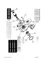
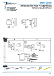
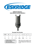
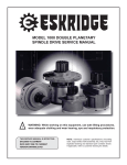
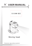
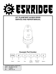
EXAMPLE PART NUMBER: 49 B 4 A 4 - 15 - 09
SERIES
OUTPUT
MOUNTING
OUTPUT
SHAFT
INPUT
MOUNTING
INPUT
SHAFT
CALIPER
CODE*
*Indicates next to last digits in caliper Part Number 01-266-0_ _0. A second caliper is optional.
49B CALIPER BRAKE
SERVICE & REPAIR MANUAL
THIS SERVICE MANUAL IS EFFECTIVE
FROM: ......... S/N 57755, SEPT. 1998
TO: .............. CURRENT
SECOND
CALIPER*
49B SERVICE MANUAL
CALIPER BRAKE
This manual will assist in disassembly and assembly of Eskridge Model 49B brakes. Item numbers, indicated in parentheses
throughout this manual, refer to the exploded parts breakdown drawing. Individual customer specifications (mounting case, output
shaft, brake assembly, etc.) may vary from exploded drawing and standard part numbers shown. If applicable, refer to individual
customer drawing for details.
For any spare or replacement parts, contact your distributor or equipment manufacturer. Always try to have available the unit
part number, serial number and date code on the serial tag. This information may be necessary for verification of any component
part numbers. Component part numbers and/or manufacturing lot numbers may be stamped on individual parts. This information
may also be helpful in identifying replacement components.
MAINTENANCE
The Model 49B Series is a modular SAE ‘B’-mounted caliper disc brake. It is designed to accept a MICO, Inc. 515 series caliper
which is available in three basic models: mechanical-apply, hydraulic-apply and spring-apply/hydraulic-release. The brake housing will accept one or two calipers. This allows calipers to be selected to meet a variety of applications that may require both
a service brake and a parking brake. The disc is aluminum-bronze for corrosion resistance in exposed applications. The shaft
is supported at the output end by a bearing protected by a lipseal. The input end of the shaft must be supported by a hydraulic
motor. A variety of motor mounts and shaft spline combinations are available.
Caliper
Code
Eskridge P/N
Description
Torque per Caliper (In-Lb)
Limits
15
08
14
09
17
13
01-266-0150
01-266-0080
01-266-0140
01-266-0090
01-266-0170
01-266-0130
Hydr.-Apply (MICO 02515030)
Mech.-Apply (MICO 02515148)
Spring-Apply (MICO 02515002)
Spring-Apply (MICO 02515004)
Spring-Apply (MICO 02515008)
Spring-Apply (MICO 02515006)
3.5 X Cylinder PSI.
30 X Lever Pull (Lb)
400-800 (Adjustable)
800-1200 (Adjustable)
1200-3200 (Adjustable)
3200-4000 (Adjustable)
2000 PSI Max*
420 LB Max
120-240 PSI Release*
230-370 PSI Release*
340-910 PSI Release*
900-1200 PSI Release*
All hydraulic calipers (apply & release) are rated for 1500 PSI Continuous, 2000 PSI Intermittent.
Use only petroleum base hydraulic oil.
Minimum useable disc thickness is .375 inches/9.53 mm (New = .500 inches/12.70 mm).
!
WARNING: While working on this equipment, wear adequate protective clothing, hearing, eye, and
respiratory protection. Use safe lifting procedures.
CONTENTS
Maintenance ......................................................................................................... 2
Installation............................................................................................................ 3
Adustment of Calipers ........................................................................................ 3
Break In ................................................................................................................ 3
Disassembly......................................................................................................... 3
Reassembly.......................................................................................................... 3
Exploded view...................................................................................................... 5
www.eskridgeinc.com
2
SM49B-AC
Installation
1)
Use only SAE grade 5 or better fasteners for mounting
brake and motor.
2)
Allow at least one bolt diameter of thread engagement
when selecting fastener lengths. Be sure fasteners will
not bottom out when fully tightened.
3)
Orient brake as required for best orientation of hydraulic
lines or cable linkage (mechanical-apply). If two calipers are
provided, their positions may be switched as desired.
4)
Bleed any air from hydraulic caliper(s) and line.
1)
Like automotive type disc brakes, the Model 49B will not
produce repeatable braking until it is properly broken in or
“burnished”. Burnishing occurs at an elevated temperature
of approximately 450° F (230° C).
2)
Make sure that the disc is free of oil and grease before
burnishing.
Break In
4)
Mounting of the brake unit requires removal of the caliper(s)
and disc. Remove one of the capscrews from caliper(s)
and swing the caliper(s) out away from the disc. Remove
the retaining ring (8) from the top of the disc and slide the
disc up and off of the shaft.
3)
Generally speaking burnishing is accomplished by slipping
the disc for approximately 200 revolutions at 2000 In-Lb of
torque or 100 revolutions at 4000 In-Lb of torque, etc. The
brake linings will emit a noticeable odor when burnishing
temperature is reached.
5)
Two mounting-hole patterns are provided: a 2-hole pattern on a 5.75 inch bolt circle and a 4-hole pattern on a
5.00 inch bolt circle. Either pattern may be used with
single-caliper units. On units with two calipers, fasteners
in the 4-hole pattern will interfere with the calipers at the
two holes nearest the calipers.
4)
It is important that burnishing be done relatively quickly
and that the disc not exceed the above recommended
temperature. Excess temperatures for a prolonged period
of time can damage the rubber lipseal (11) between the
brake housing and shaft.
6)
See chart for fastener torque specifications.
5)
Refer to the enclosed bulletin, MICO Burnishing Procedures
for Caliper Disc Brakes, Form No. 81-950-016, for further
details.
1)
Remove hexhead capscrew (5) and caliper(s) (10, 13).
2)
Remove beveled retaining ring (8) and slide disc (3) up
and off of shaft (2). Note: Newer models may use a spiral
type retaining ring in lieu of a beveled ring.
3)
Remove capscrews (14) and remove brake assembly from
its mounting.
4)
Remove retaining ring (6) from housing (1).
5)
Position housing (1) with output end up. Press shaft (2)
out of bearing (4).
6)
Remove retaining ring (9) from housing (1).
7)
Using a 1.63 to 1.75” diameter press tool, press the shaft
(2) out of bearing (4). The shaft (2) may be used as a
press tool but this will destroy lipseal (11).
Refer to the appropriate MICO Installation and Service
Instructions for details concerning your caliper(s).
8)
Press the lipseal (11) from the housing (1).
1)
When attaching hydraulic lines, note that the hydraulicapply caliper (with green piston body) has a 1/8-27 NPT
port. The spring-apply/hydraulic-release caliper has a No.
4 SAE O-ring port and is furnished with a JIC 37°-flare
elbow fitting.
9)
Clean and inspect all parts. Refer to the exploded drawing
for P/N’s of seal kit and replacement pad kit. Replacement parts and calipers assemblies are available through
Eskridge Customer Service. Refer to the MICO bulletin
and contact MICO customer service for caliper individual
replacement parts.
2)
It is critical that the caliper(s) be free to float after adjustment
of the threaded piston body to desired torque (spring-applied) or recommended running clearance between brake
linings and disc (hydraulic & mechanical-apply). The elbow
that is provided with the spring-apply/hydraulic-release
caliper must clear the brake housing while in the released
position.
1)
Press a new lipseal (11) into housing (1). Pack lipseal
with grease.
2)
Pack bearing (4) with grease and press into housing (1)
with shieded end away from lipseal (11).
3)
Install retaining ring (9).
4)
From input end, press shaft (2) through lipseal (11) and
THREAD
SIZE
3/8-16
1/2-13
5/8-11
3/4-10
7)
8)
T O R Q U E IN F T - L B S
SAE GRADE 5
SAE GRADE 8
DRY LUBED
DRY
LUBED
30
23
45
35
75
55
110
80
150
110
220
170
260
200
380
280
Disassembly
The retaining ring at the top of the disc has a beveled face.
Reinstall the ring with the beveled face up or away from the
disc. Note: Newer models may use a spiral type retaining
ring in lieu of a beveled ring. When reinstalling the spiral
ring, it must be fully seated (the entire perimeter of the ID
must be captured beneath the edge of the beveled shaft
groove)
Reinstall the caliper retaining bolts making sure that the
caliper is free to float with the disc.
Adustment of Calipers
3)
Reassembly
Use only mineral base hydraulic oil to pressurize hydraulic
type calipers. They are not designed for use with SAE
brake fluids. Brake fluids will attack and destroy the internal
rubber seals.
www.eskridgeinc.com
3
SM49B-AC
The caliper for this brake is manufactured by MICO. For
a a file containing the below MICO forms, which may apply to your brake’s caliper, call Eskridge at 913-782-1238
and request TB49B-MICO-AA for MICO literature supporting the caliper.
into bearing (4). This will likely roll under the outer lip
on the lipseal. To correct this, press the shaft back out
approximately 1/16 inch. Then press back into place.
Important: Do not apply excess force when pressing
bearing. Excess force may cause bearing balls to yield
the inner or outer races. This will cause the bearing to
run rough.
5)
Install retaining ring (6) on shaft (2).
6)
Reassemble all remaining parts in reverse of the Disassembly steps above. Note that the lower disc retaining
ring (7) has no beveled face. The upper retaining ring
(8) is the same size but may have a beveled face. The
beveled face must be up, away from disc. Note: Newer
models may use a spiral type retaining ring in lieu of a
beveled ring. When reinstalling the spiral ring, it must be
fully seated (the entire perimeter of the ID must be captured
beneath the edge of the beveled shaft groove)
7)
MICO Form No. 81-600-001, General Guidelines for Installing
Hydraulic Brake Components
MICO Form No. 81-950-016, Burnishing Procedures for Caliper
Disc Brakes
MICO Form No. 81-515-007, Installation and Service Instuctions, Spring Apply Caliper Brakes
MICO Form No. 81-515-008, Installation and Service Instructions, Hydraulic Apply Caliper Brakes
MICO Form No. 81-515-009, Installation and Service Instructions, Mechanical Caliper Brakes
Perform the Break In (burnishing ) procedure if the disc
(3), the caliper(s) (10, 13) or the lining pads have been
replaced.
THE BRAKE IS NOW READY TO USE.
www.eskridgeinc.com
4
SM49B-AC
14
13
09
08
CALIPER - HYD. APPLY
CALIPER - SPRING APPLY
CALIPER SPRING APPLY
CALIPER - SPRING APPLY
CALIPER - MECH. APPLY
CALIPER OPTION
01-266-0170
01-266-0150
01-266-0140
01-266-0130
01-266-0090
01-266-0080
PART NO.
CODE
15
CALIPER - SPRING APPLY
3
B
11
17
6*
Table
49-004-1193
PART NO.
49-004-1183
SHAFT OPTIONS
14T 12/24 IN: 14T 12/24 OUT
49-004-1173
14T 12/24 IN: 13T 16/32 OUT
14T 12/24 IN: 1-6B OUT
C
1
13
5
10
8
7
2
9
PART NO.
49-004-2073
49-004-2083
SAE 'A' IN: SAE 'B' OUT
49-004-2084
9
8
7
6
5
4
3
2
1
1
1
1
1
1
1
1
1
*
1
1
CALIPER
SHAFT
HOUSING ASS'Y
O-RING (#242)
LIP SEAL (NAT 472164)
SNAP RING (3000-268)
SNAP RING (5102/WST-206)
SNAP RING (5100-206)
SNAP RING (5100-156)
HHCS (1/2-13 x 3.75 GR8)
BEARING (#6008)
ROTOR - BRONZE
-C-
-B-
-A-
01-402-0220
01-405-0170
01-160-0100
01-160-0450
01-160-0250
01-160-0110
01-150-1250
01-100-0180
49-004-1122
P/N
10
*
DESCRIPTION
12
11
ITEM QTY
SAE 'B' IN: SAE 'B' OUT
SAE 'A' IN; SAE 'B' OUT, DUAL CALIPER
HOUSING PILOT
PACK WITH GREASE
AND INSTALL SHIELDED
SIDE AWAY FROM
LIPSEAL ITEM 11
4
X49B-AB.IDW
EFFECTIVE
FROM S/N 57755 9-15-98
TO: CURRENT
A
10
NOTES:
1. A SECOND CALIPER IS OPTIONAL, ITEM 3 IS 2 OR 4 ACCORDINGLY
2. HOUSING IS PROVIDED WITH 2 & 4 BOLT PATTERNS FOR UP TO 6 MOUNTING CAPSCREWS.
WITH DUAL CALIPERS, 2 CAPSCREWS IN 4 BOLT PATTERN WILL INTERFERE WITH CALIPERS
3. CALIPER MAY BE MOUNTED IN MIDDLE POSITION (AS SHOWN), OR EITHER SIDE POSITION
4. MINIMUM USABLE ROTOR THICKNESS IS .375" (NEW = 0.500'")
5. SEAL KIT IS P/N 49-01601201 (INCLUDES ITEM 8 & 9) REPLACEMENT PAD KIT (ALL CODES)
IS P/N 01-266-0160. ONE KIT PER CALIPER. CALIPER (ITEM 12) MUST BE REPLACED AS A UNIT.
NO SEAL KIT IS AVAILABLE.
6. ITEM 6 MAY BE EITHER A MULTI-TURN SPIRAL RETAINING RING, OR A BEVELED SNAPRING.
WHEN USING BEVLED RING, BEVELED EDGE MUST FACE AWAY FROM DISC.
SM49B-AC
5
www.eskridgeinc.com