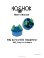
1
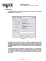
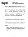
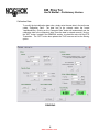
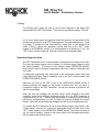
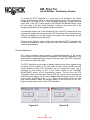
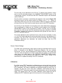
User’s Manual
920 Series RTD Transmitter
920_Prog Txr Software
www.noshok.com
www.comoso.com
920_Prog Txr
User’s Manual – Preliminary Version
Table of Contents
System Requirements ......................................................................................................3
Installing the Software ......................................................................................................3
Uninstalling the Software ..................................................................................................3
Reading Device Configuration ..........................................................................................4
Programming Device ........................................................................................................5
Changing Device Settings .............................................................................................5
TAG Name..................................................................................................................5
Calibration Date ..........................................................................................................6
Filtering.......................................................................................................................7
Operation Range and Units ........................................................................................7
Current Adjustment.....................................................................................................8
Sensor Failure Settings ..............................................................................................9
Calibration .....................................................................................................................9
“One Point” Calibration .............................................................................................10
“Two Point” Calibration .............................................................................................10
Wiring Diagrams..........................................................................................................11-12
2
www.comoso.com
920_Prog Txr
User’s Manual – Preliminary Version
System Requirements
To install the 920_Prog Txr Software, you need these minimum system requirements:
•
•
•
•
•
Pentium III – 600 MHz or better
10 MB of Hard Disk space
256 MB of RAM
Windows XP or VISTA
1 USB port
Installing the Software
*** IMPORTANT ***
If you already have an old version of the 920_Prog Txr Software on your computer
you must first uninstall it. To do so, use the Windows Add/Remove Program utility in
the Control Panel.
*** IMPORTANT ***
For the 920_Prog Txr Software to work properly on your computer you must have the
decimal symbol set to the dot (.) in Windows. To verify or modify that option open
the “Regional and Language Options” in the Windows Control Panel and select the
“Regional Options” tab. Click on the “Customize…” button and then make sure the
dot (.) is used for the decimal symbol.
•
•
•
•
•
Install the USB driver by running the “CP210xVCPInstaller” program located in the root
directory of the CD.
Run the “920_Prog Txr .MSI” program located in the root directory of the CD.
The 920_Prog Txr Setup program will automatically start.
By default, the 920_Prog Txr Software will be installed in the “Program Files\920_Prog
Txr ” directory. You can change the installation directory by clicking on the “Change
Directory” button during the setup procedure.
After the installation is completed, the 920_Prog Txr Software will be accessible via the
Start-Program menu of Windows.
Uninstalling the Software
To uninstall the software, use the “Add/Remove Program” utility in the Control Panel of
Windows. The program and all its associated files will be automatically deleted from your
computer.
3
www.comoso.com
920_Prog Txr
User’s Manual – Preliminary Version
Reading Device
By launching the 920_Prog Txr Software, the main window of the 920_Prog Txr software
will appear on the screen (Figure #1).
FIGURE #1
To establish the communication between the 920_Prog Txr software and the RTD
transmitter, click on the “Read Device” button. The software will automatically scan all the
communication ports available on the computer and will try to establish the communication
with the RTD transmitter. Once the communication is established, the right section of the
main window (“Device Information”) will be updated with the values downloaded from the
transmitter.
If the communication cannot be established, a message will appear on the screen asking
for a manual connection. By clicking “Yes”, the manual connection dialog box will appear.
The proper communication port must then be selected in the drop down list and clicking on
the “Read Device” button will make an attempt to establish the communication through the
selected port.
4
www.comoso.com
920_Prog Txr
User’s Manual – Preliminary Version
The communication ports available on the computer can be seen in the Device Manager of
Windows. The USB driver automatically creates a virtual COM port when the
communication module is connected and will appear in the Device Manager under the
section “Ports” - “Silicon Labs CP210x”.
If the communication is established, all the information is downloaded from the RTD
Transmitter and the right section of the main windows (“Device Information”) is updated
with the actual values. If the communication cannot be established an error message will
appear. If the communication port cannot be found the message will display
“Communication Port Not Available”. This means the communication port selected is not
configured on the computer or used by another peripheral. If the communication port is
valid but the communication cannot be established with the RTD Transmitter, the message
will display “Device not found”. In this case make sure the RTD Transmitter is connected to
the communication port selected and the wiring was made correctly. Once the
communication with the RTD Transmitter is established, the “Program” button will become
enabled. Clicking on this button will give access to the programming window.
Programming Device
The programming window (FIGURE #2) allows you to change the device settings, the
operating range and re-calibrate the device.
Changing device settings:
The “Settings” section of the programming window includes all the configurable settings
device. The “General” section contains the TAG name, the last calibration date and the
filtering options.
TAG Name:
The TAG name is used to identify the device. It can contain a maximum of eight (8)
alphanumeric characters. To set or change the TAG name, simply enter the value in
the text box called TAG in the GENERAL section of the programming window. If the
name entered is more than eight characters only the first eight will be saved. To
upload the TAG name into the device , click on the “SET” button in the GENERAL
section. The “SET” button also updates the calibration date as well as the filtering
option.
5
www.comoso.com
920_Prog Txr
User’s Manual – Preliminary Version
Calibration Date:
To modify the last calibration date value, simply enter the new date in the text boxes
called “Calibration Date”. The date has to be entered under the format
Year/Month/Day. Clicking on the “Computer Date” button will automatically set the
calibration date to the computer’s date. Once the date is entered correctly, click on
the “SET” button, located in the GENERAL section, to upload the value into the RTD
Transmitter . The “SET” button also updates the TAG name as well as the filtering
option.
FIGURE #2
6
www.comoso.com
920_Prog Txr
User’s Manual – Preliminary Version
Filtering:
The filtering option allows the user to set the time response of the digital filter
implemented in the RTD Transmitter . There are four (4) different settings. The first
one is “none” which means the response time of the output is only dependent of the
mechanical construction of the RTD sensing portion. The other settings are 1, 3 and
5 seconds. To change the filter response time, simply click on the selection box
called “Filtering”, choose the appropriate setting and click on the “SET” button
located in the GENERAL section. It is recommended to set filtering to 1 sec. The
“SET” button will also update the TAG name as well as the calibration date.
Operation Range and Units:
The RTD Transmitter can be re-scaled within its construction limit range at any time.
The user can choose among a list of thirteen (13) different preset ranges or enter
the values manually. This section of the software, called OPERATION RANGE,
allows also the user to change the engineering units from Celsius to Fahrenheit and
vice versa.
To change the engineering units, simply click on the selection box called “Units” and
select the desired value. Once it is selected, click on the “SET” button located in the
OPERATION RANGE section.
Each time you click on the “SET” button of the OPERATION RANGE section, a
warning message will appear on the screen, indicating that you are about to
re-scale the output of the RTD Transmitter. You can then choose to proceed or not
with the new settings.
When the units are changed, the operation range is also changed to the same
numerical values but in different engineering units. (Ex. If a RTD Transmitter is
configured as a 0 to 100 °C and the units are changed to Fahrenheit then the device
will become configured as a 0 to 100 °F). When the units are changed, the “Preset
Range” values are also automatically changed to match the new engineering units.
To re-scale the RTD Transmitter to one of the pre-defined range, simply click on the
“Preset Range” selection box, choose the appropriate range and then click on the
“SET” button located in the OPERATION RANGE section. Once the new range is
set, the “Actual Reading”, located in the bottom right of the Programming window,
will be updated with the new values.
7
www.comoso.com
920_Prog Txr
User’s Manual – Preliminary Version
To re-scale the RTD Transmitter in a range that is not included in the “Preset
Range”, simply enter the value, in the current engineering units, that corresponds to
a reading of 4 mA and 20 mA, in their respective text boxes. To apply this new
range, click on the “SET” button located in the OPERATION RANGE section. Once
the new range is set, the “Actual Reading”, located in the bottom right of the
Programming window, will be updated with the new values.
If the selected range is out of the construction limit of the RTD Transmitter an error
message will appear on the screen and the RTD Transmitter will not accept this new
setting.It is important to note that changing the range and/or engineering units will
not affect the calibration previously done.
Clicking on the “Reset to Factory” button will re-program the RTD Transmitter with
its range and calibration values as they were set at the factory according to the
customer specifications.
Current Adjustment:
The current adjustment feature permits a verification/adjustment of the current
output against a current loop indicator independent of the sensor temperature. It can
also be used for troubleshooting by simply forcing the output of the RTD Transmitter
to its 4.00 mA or 20.00 mA values.
The RTD Transmitter current output is already adjusted at the factory against a high
accurately current indicator. If the user wants a perfect match between his loop
current indicator and the RTD Transmitter, he can re-adjust the output. This is
performed by first clicking on the “4 mA” button located in the CURRENT
ADJUSTMENT section of the Programming window. This will force the RTD
Transmitter output to the theoretical value of 4.00 mA. Once the button is pressed, a
small dialog box appears on the screen (Figure 3-A) allowing the user to set the
output current, by clicking on the “+” or “-” button, to read exactly 4.00 mA on his
loop current indicator. When the indicator reads 4.00 mA then click on the “Set”
button to record the new value in the RTD Transmitter
Figure 3-A
8
www.comoso.com
Figure 3-B
920_Prog Txr
User’s Manual – Preliminary Version
The next step is the adjustment of the 20 mA. To perform that operation, simply
click on the 20 mA button located in the CURRENT ADJUSTMENT section of the
“Programming” window. This will force the RTD Transmitter output to the theoretical
value of 20.00 mA.
Once the button is pressed, a small dialog box appears on the screen (Figure 3-B)
allowing the user to set the output current, by clicking on the “+” or “-” button, to
read exactly 20.00 mA on his loop current indicator. When the indicator reads 20.00
mA then click on the “Set” button to record the new value in the RTD Transmitter.
The last step is the calculation and recording of the output adjustment parameters.
This is performed by clicking on the “Process” button located in the CURRENT
ADJUSTMENT section of the “Programming” window. The 920_Prog Txr program
then reads the 4.00 mA and 20.00 mA values that have been set earlier in the RTD
Transmitter, calculates the adjustment parameters and uploads the new values in
the RTD Transmitter memory.
The current adjustment can be performed at any time and not necessarily in order
(i.e. the 20 mA output adjustment can be performed before the 4 mA adjustment). If
necessary, only one of the 4 mA or 20 mA can be performed. When the current
adjustment parameters are calculated, the values are taken from the RTD
Transmitter memory.
Sensor Failure Settings:
The failed value represents the output value at which the transmitter will be set if a
failure is detected on the Resistive Temperature Detector. The two available
choices are “<2.5 mA”, which correspond to an output of about 2.5 mA or lower, and
“>24 mA”, which correspond to an output of about 24 mA or higher. To set the failed
value click on the radio button, in the SENSOR FAILURE SETTINGS section,
corresponding to your choice and then click on the “SET” button, located in the
same section, to update the setting in the RTD Transmitter.
Calibration:
By default, every RTD Transmitter is calibrated at one point at the factory but the
user can, with the help of the 920_Prog Txr software, re-calibrate or re-scale the
RTD Transmitter. Two types of calibration are available through the 920_Prog Txr
software. The first one is the “One point” calibration, which allows the user to
calibrate the RTD Transmitter against one known temperature value in the operating
range. The second type is the “Two point” calibration, which allows the user to
calibrate the RTD Transmitter against two known points in the operating range.
9
www.comoso.com
920_Prog Txr
User’s Manual – Preliminary Version
“One Point” Calibration
The “One point” calibration allows the user to offset the output of the RTD
Transmitter to match perfectly a known temperature to which the RTD Transmitter is
set.
To perform this calibration, a known and stable temperature reference is required.
Set the RTD Transmitter to this known reference temperature and wait long enough
to be sure that the reading is stabled. To establish what the output current should be
at this reference temperature, the user can enter the value of the reference
temperature (in the current engineering units) in the corresponding text box (“For a
Temperature of “) located in the “1 POINT CALIBRATION” section of the
“Programming” window.
The theoretical output current will then be automatically calculated and displayed in
the corresponding text box (“theoretical output should be “). If the current indicated
by the loop current indicator does not match the theoretical value, then click on the
“+” or “-” button of the “Adjustment” section to adjust the output reading to the
correct value. Every time the “+” or “-” buttons are clicked, the new value is
uploaded and saved in the RTD Transmitter memory.
NOTE:
The “Actual Reading” section located on the bottom right section of the
Programming window displays values calculated by the 920_Prog Txr
program. This calculation is based on the digital reading (via the USB)
and may not correspond exactly to the current output read by the loop
indicator. For better accuracy, use the reading from a calibrated loop
indicator to make the adjustments.
“Two Point” Calibration
The “Two point” calibration allows the user to calibrate the RTD Transmitter against
two known reference temperatures in the operation range. This calibration is
performed in three steps.
The first step is the “First Point” reading. The RTD Transmitter has to be set at a
known and stable reference temperature inside its operating range. The first point
must be at a lower value then the “Second Point”. Once the output reading from the
RTD Transmitter is stable, enter the temperature value in the text box called “First
Point:” located in the 2 POINTS CALIBRATION section, and click on the
corresponding “Read” button. The input value is then saved in the RTD Transmitter
memory as well as the temperature reference for the first point.
The second step is the “Second Point” reading. The RTD Transmitter has to be set
at a known and stable reference temperature inside its operating range. The second
10
www.comoso.com
920_Prog Txr
User’s Manual – Preliminary Version
point must be at a higher value than the “First Point”. Once the output reading from
the RTD Transmitter is stable, enter the temperature value in the text box called
“Second Point:” located in the 2 POINTS CALIBRATION section, and click on the
corresponding “Read” button. The input value is then saved in the RTD Transmitter
memory as well as the temperature reference for the second point.
The third and last step is to perform the calculation of the calibration parameter.
This is done by clicking on the “Process” button located in the 2 POINTS
CALIBRATION section. This action causes the 920_Prog Txr software to download
the first and second point values from the RTD Transmitter and calculates the
calibration parameters from a linear extrapolation between the two points recorded.
The new calibration parameters are then uploaded and saved in the RTD
Transmitter memory. The output of the RTD Transmitter is automatically
recalculated without having to re-initialize it.
NOTE:
The reading of the first and second calibration points do not have to be
performed at the same time or in the order indicated.
Wiring Diagrams
www.comoso.com
Corporate Headquarters
1010 West Bagley Road , Berea, Ohio 44017
Ph: 440.243.0888
Fax: 440.243.3472
E-mail: [email protected]
Web: www.noshok.com
UM920 Rev. 1
www.comoso.com