1
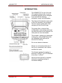
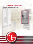
LG TRAINING MANUAL
Over-the-Range Microwave LMVM2277ST
Spring 2008
Published January 2008 by LG Electronics USA Trainng Center
Customer Service (and Part Sales): (800) 243-0000
Technical Support (and Part Sales): (800) 847-7597
Training Center: (256) 774-4051
USA Website: www.lgusa.com (us.lge.com)
Customer Service Website: us.lgservice.com
B2B Service Website: aic.lgservice.com
Training Website: www.LGCSAcademy.com
LMVM2277ST
MICROWAVE OVEN
LMVM2277ST (Over-The-Range Microwave Oven)
CONTENTS
Safety Notice, Other Notices, and Disclaimer
Introduction
Specifications
Warranty Page
General Warnings and Safety Information
Oven Installation
Turntable Installation
Operating Instructions
Power Levels
Care and Cleaning
Oven Exterior
Oven Interior
Grease Filters
Charcoal Filter
Oven Light Replacement
Disassembly and Repair
Power Board and Main Board
Outer Case Removal
Door Interlock Switches
Interlock Switch Continuity Test
Primary and Secondary Switches
Monitor Switch
Magnetron Removal and Replacement
Stirrer Fan and Cover
Door Removal
Door Disassembly
Flat Plastic Connector
Vent Fan Motor Replacement
Turntable Motor Replacement (with oven installed)
Humidity Sensor
Component Test Procedures
Transformer Test
Magnetron Test
Capacitor
Relay
Fan Motor
Low Voltage Transformer
1
3
4
5
6
7
8
9
10
12
13
13
13
13
14
15
16
16
18
19
20
20
20
21
21
22
23
24
26
26
26
27
27
27
28
29
29
29
Ver. 1.0 080205
LMVM2277ST
Page 1
TRAINING MANUAL
LMVM2277ST
MICROWAVE OVEN
Component Test Procedures (continued)
High Voltage Diode
Turntable Motor
Ventilation Van /Motor
Humidity Sensor
Stirrer Fan Motor
Microwave Leakage Test Procedure
Microwave Power Test Procedure (Traditional Method)
Microwave Power Test Procedure (Alternate Method)
Checkout Procedures
Blown Fuse
Main PCB (Printed Circuit Board)
Relay
Troubleshooting Flow Charts
Chart A – No Power
Chart B – Power, Doesn’t Run
Chart C – Runs, No Heat
Chart D – Counts Down, No Heat
Chart E – No Beeper (Buttons or End of Cycle)
Chart F – Power Supply
Main Board
Exploded View
Exploded View – Door Parts
Exploded View – Case Parts
Exploded View – Safety Switched
Exploded View – Internal Parts
Exploded View – Air Duct, Fan, Sensor, and Wiring Parts
Exploded View – Installation Parts
Parts List
Model Number / Serial Number Decoding Chart
Supplemental Materials
Chart – Ohm’s Law and Watt’s Law
Conversion Formulae - °F / °C
Schematic (Oversize, folded in back of book)
LMVM2277ST
Page 2
30
30
31
31
31
32
33
34
35
38
38
38
39
41
41
42
43
44
46
47
48
49
49
50
51
52
53
54
55
58
59
59
60
TRAINING MANUAL
LMVM2277ST
MICROWAVE OVEN
IMPORTANT SAFETY NOTICE
The information in this training manual is intended for use by persons possessing an adequate background
in electrical equipment, electronic devices, and mechanical systems. In any attempt to repair a major
appliance, personal injury and property damage can result. The manufacturer or seller maintains no liability
for the interpretation of this information, nor can it assume any liability in conjunction with its use. When
servicing this product, under no circumstances should the original design be modified or altered without
permission from LG Electronics. Unauthorized modifications will not only void the warranty, but may lead to
property damage or user injury. If wires, screws, clips, straps, nuts, or washers used to complete a ground
path are removed for service, they must be returned to their original positions and properly fastened.
CAUTION
To avoid personal injury, disconnect the power before servicing this product. If electrical power is required
for diagnosis or test purposes, disconnect the power immediately after performing the necessary checks.
Also be aware that many household appliances present a weight hazard. At least two people should be
involved in the installation or servicing of such devices. Failure to consider the weight of an appliance could
result in physical injury.
ESD NOTICE
Some of the electronics in appliances are electrostatic discharge (ESD) sensitive. ESD can weaken or
damage the electronics in these appliances in a manner that renders them inoperative or reduces the time
until their next failure. Connect an ESD wrist strap to a ground connection point or unpainted metal in the
appliance. Alternatively, you can touch your finger repeatedly to a ground connection point or unpainted
metal in the appliance. Before removing a replacement part from its package, touch the anti-static bag to a
ground connection point or unpainted metal in the appliance. Handle the electronic control assembly by its
edges only. When repackaging a failed electronic control assembly in an anti-static bag, observe these
same precautions.
REGULATORY INFORMATION
This equipment has been tested and found to comply with the limits for a Class B digital device, pursuant to
Part 15 of the FCC Rules. These limits are designed to provide reasonable protection against harmful
interference when the equipment is operated in a residential installation. This equipment generates, uses,
and can radiate radio frequency energy, and, if not installed and used in accordance with the instruction
manual, may cause harmful interference to radio communications. However, there is no guarantee that
interference will not occur in a particular installation. If this equipment does cause harmful interference to
radio or television reception, which can be determined by turning the equipment off and on, the user is
encouraged to try to correct the interference by one or more of the following measures: Reorient or relocate
the receiving antenna; Increase the separation between the equipment and the receiver; Connect the
equipment to an outlet on a different circuit than that to which the receiver is connected; or consult the
dealer or an experienced radio/TV technician for help.
DISCLAIMER
The information in this training manual was accurate at the time of publication. Every effort has been made
to ensure accuracy. Updates, changes, etc. are available via GCSC and LGCSacademy. The information in
this manual is intended for persons with adequate backgrounds in electronics, mechanical, and electronic
servicing. The manufacturer and seller are not to be held responsible for any liability incurred from its use.
COMPLIANCE
The responsible party for this device’s compliance is LG Electronics Alabama, Inc.; 201 James Record Road,
Huntsville, AL, 35813.
LMVM2277ST
Page 3
TRAINING MANUAL
LMVM2277ST
MICROWAVE OVEN
INTRODUCTION
The LMVM2277ST is part of the new
LG complete kitchen suite. It can be
purchased separately but is designed
to be sold with the matching
refrigerator, range, and dishwasher.
This diagram illustrates the major parts
of the oven as seen by the customer.
The door opens upward rather than
swinging out from the left hinge.
The grease filters, charcoal filter,
cooktop lights, and cooking cavity light
can all be serviced by the customer. No
other parts are user-serviceable.
The turntable, rotating ring, rectangular
cooking tray, and turntable drive cam
are dishwasher safe and may be
removed for cleaning.
Do not use abrasive cleansers.
Always run a microwave leak test. If
the oven is operational, test it before
and after the repair.
The Federal standard for leakage is
less than 5 mW/cm2, but LG’s standard
is less than 1 mW/cm2.
See the service manual for complete
information regarding testing for
microwave leakage.
LMVM2277ST
Page 4
TRAINING MANUAL
LMVM2277ST
MICROWAVE OVEN
SPECIFICATIONS
Rated Power Consumption
Microwave Output
Frequency
Power Supply
Rated Current
Magnetron Cooling
Rectification
Door Ceiling
Safety Devices
Magnetron
Cooktop Lamps
Cavity Lamp
Timer
Tray
Cavity Capacity
Accessories
1,700 W max (MWO + lights + fan)
1,100 W (IEC 60705)
2,450 MHz ± 50 MHz
120 V AC, 60Ø
14.5 Amps (MWO + lights + fan)
Forced Air Cooling
Voltage Double Half-Wave
Choke System
Magnetron Thermostat
Open @ 145° C ± 5° C (293° F ± 9° F)
Close @ 60° C ± 5° C (140° F ± 9° F)
Oven Thermostat
Open @ 110° C ± 5° C (230° ± 9° F)
Close @ 0° C ± 5° C (32° F ± 9° F)
Ambient Oven Thermistor
Open @ 82° C ± 5° C (180° F ± 9° F)
Close @ 54° C ± 5° C (130° F ± 9° F)
Fuse (20 Amps)
Primary Interlock Switch
Secondary Interlock Switch
Interlock Monitor Switch
2M282H (Toshiba)
12 V, 10 W (Halogen)
12 V, 20 W (Halogen)
Digital to 99:99 in each cooking stage
Tempered Safety Glass
2.2 cu. ft.
Owner’s manual, cooking guide,
exhaust adapter, exhaust damper, mounting
kit, filter, rotating ring assembly, glass tray,
metal rack, defrost plate
SWITCH CHART
Switch Mode
Primary
Secondary
Monitor
Conditions
COM
NO
OPEN
CLOSE
COM
NO
OPEN
CLOSE
COM
NC
CLOSE
OPEN
Door Open
Door Closed
LMVM2277ST
Page 5
TRAINING MANUAL
LMVM2277ST
MICROWAVE OVEN
WARRANTY
LMVM2277ST
Page 6
TRAINING MANUAL
LMVM2277ST
MICROWAVE OVEN
GENERAL WARNINGS and SAFETY INFORMATION
•
Always unplug the oven to disassemble or repair it.
•
Never operate the microwave oven when it is empty. When cooking very
small amounts of food, put a glass of water in the cooking compartment.
•
Do not operate the oven on a 2-wire extension cord during repair or use.
•
Use proper ESD precautions when handling the PCB.
•
Never put anything into the latch holes and interlock switches.
•
Remove your watch before working on or around the magnetron.
•
Do not operate the oven without the glass tray / turntable in place.
Be sure the magnetron gasket is
properly installed around the dome of
the tube whenever installing the
magnetron.
See magnetron section, page 21.
Always use a properly wired and
grounded 3-wire dedicated outlet to
power the oven. (120 VAC, 20 A.)
Never cut the ground prong off the
plug or otherwise defeat the grounding
of this appliance.
LMVM2277ST
Page 7
TRAINING MANUAL
LMVM2277ST
MICROWAVE OVEN
OVEN INSTALLATION
The LMVM2277ST must be
properly installed before
operation. Installation includes
mounting the bracket on the
wall with toggle bolts and/or lag
bolts and drilling holes in the
cabinet above the oven to
accommodate the electric cord
and the upper mounting bolts.
A template is provided for
locating the holes properly.
The ventilation fan can exhaust
air in any of three directions:
through the back wall, through
the roof, or recirculated through
the charcoal filter into the
kitchen. If the air is vented
through a duct to the outside,
the damper and flap must be
installed.
LMVM2277ST
Page 8
TRAINING MANUAL
LMVM2277ST
MICROWAVE OVEN
TURNTABLE INSTALLATION
The turntable is a multi-part
arrangement that includes a
round glass tray that rotates and
a rectangular glass tray that
moves laterally at the same
time. Smaller dishes sit on the
round tray while they rotate and
move laterally; larger dishes sit
on the rectangular tray and
move laterally.
1
Round glass tray
2
Rotating ring
3
Rectangular glass tray
4
Turntable drive arm
Follow these steps to install the turntable components and to ensure they
function correctly.
1. Install the
turntable drive arm
and position it
securely on the
drive cam.
2. Install the
rectangular glass
tray and ensure it
slides properly.
3. Place the
rotating ring on
top of the
rectangular glass
tray.
4. Be sure the
drive arm can
rotate in the
hollow area on the
bottom of the
rectangular tray.
Place the round glass tray on top of the rotating ring. Put a
cup of water on the turntable and operate the oven for a
minute to ensure that the tray mechanism is seated properly
and works as it should. There should be rotation on the
turntable AND lateral motion involving the rectangular tray.
LMVM2277ST
Page 9
TRAINING MANUAL
LMVM2277ST
MICROWAVE OVEN
OPERATING INSTRUCTIONS
All functions are available from the
control panel. Operation is similar to
most other microwave ovens.
For example, to set two-stage cooking
with a cook time of 3 minutes at full
power and 7 minutes, thirty seconds at
a power level of 70%,
press 3, 0, 0, and COOK TIME to set
the 3 minutes at full power, then press
7, 3, and 0 to set the second cooking
time of seven minutes, thirty seconds,
then press POWER LEVEL and 7 to
set the power level of the second
cooking period to 70%, and then press
START.
All other functions operate in a similar
manner. See the owner’s manual for
complete operating instructions.
LMVM2277ST
Page 10
TRAINING MANUAL
LMVM2277ST
MICROWAVE OVEN
When the oven is first plugged in, or
after a power failure, the display will
flash the message PLEASE SET THE
TIME OF DAY. If the time is not set,
the colon (:) will display until you touch
CLOCK.
To set the clock, touch CLOCK, the
numbers (0 through 9) to set the time,
START, and START again.
To operate the ventilation fan, touch
VENT ON/OFF, then touch + or - to
adjust the speed.
To run the fan for a set period, turn it
on and set the desired speed, as
illustrated above. Then touch AUTO
TIME SET several times to increase
the time before the fan is turned off.
To toggle the CHILD LOCK feature
ON or OFF, touch and hold the
START/CHILD LOCK button for
5 seconds until a beep sounds.
The EZ-ON button turns the oven on at
full power for 30 seconds. To cook for 2
minutes, press it four times.
To use the timer without operating the
oven, press TIMER ON/OFF, the
numbers of the time to set, and TIMER
ON/OFF.
The timer will count down and beep at
the end of the set period.
LMVM2277ST
Page 11
TRAINING MANUAL
LMVM2277ST
MICROWAVE OVEN
POWER LEVELS
Eleven power levels are available, from 0% to 100% in 10% increments. The
magnetron output is not adjustable; that is, it is either on or off. To achieve lower
power levels, a relay is used to cycle the magnetron on and off. A magnetron
warm-up period of two seconds is included in each ON cycle.
Power Level
0%
10%
20%
30%
40%
50%
60%
70%
80%
90%
100%
Warm-up Time
2 sec.
2 sec.
2 sec.
2 sec.
2 sec.
2 sec.
2 sec.
2 sec.
2 sec.
On Time
magnetron is off
2 sec.
4 sec.
6 sec.
8 sec.
10 sec.
12 sec.
14 sec.
16 sec.
18 sec.
magnetron is on
Off Time
18 sec.
16 sec.
14 sec.
12 sec.
10 sec.
8 sec.
6 sec.
4 sec.
2 sec.
Lower power levels can be used to thaw frozen items and to soften butter or
margarine. Intermediate power levels are used to cook foods more delicately
than using high power. 0% power can be used to insert standing time between
two cook cycles, such as between defrosting and cooking, to allow the food to
stand and defrost completely before beginning the cooking process.
LMVM2277ST
Page 12
TRAINING MANUAL
LMVM2277ST
MICROWAVE OVEN
CARE and CLEANING
Cleaning the oven is easy. Always unplug the oven before cleaning the control
panel to avoid touching too many buttons at once and damaging the
microprocessor.
OVEN EXTERIOR
To clean the outside of the oven, use a soft cloth and spray glass cleaner. Spray
the glass cleaner onto the cloth rather than onto the oven. DO NOT USE
abrasive cleanser, steel wool, scrubbing pads, gritty washcloths, rough paper
towers, and those sorts of things. They can damage the finish on your oven.
OVEN INTERIOR
To clean the inside of the oven, remember that it is easiest if you wipe out the
oven and clean any spatters as soon as the cooking is completed. This prevents
the spatters from being baked onto the oven surfaces during subsequent cooking.
Be especially careful to clean the area where the door closes and touches the
frame of the oven.
For stubborn soils inside the oven, put a large container of water in the oven and
run the oven for 10 minutes. (A 2-cup microwave-safe glass measuring cup
works well for this.) The steam will soften soils and allow them to be wiped away
with a damp towel. If you cut up a lemon and put it into the water during the
cooking, your oven and entire kitchen will be citrusy fresh,
GREASE FILTERS
The grease filters (on the bottom of the oven) should be removed and cleaned
monthly.
Push the tab backward and allow the
filters to drop out of their holders. Clean
them by swishing them in hot, soapy
water and rinsing them. Shake them to
dry them and replace them in their
holders.
DO NOT OPERATE the oven without
the grease filters in place.
LMVM2277ST
Page 13
TRAINING MANUAL
LMVM2277ST
MICROWAVE OVEN
CHARCOAL FILTER
If the oven is vented to the outside, the charcoal filter is not used. Leaving it in
place will not cause a problem. If the oven recirculates the air back into the
kitchen, the charcoal filter should be replaced every 6 ~ 12 months. It is not
washable and must be replaced. DO NOT OPERATE the oven without the
charcoal filter in place, unless, of course, the oven is vented to the outside.
The charcoal filter part number is 5230W1A0003A.
Remove the two screws at the top of the
oven housing. (These are the two
middle screws.) If the oven is properly
installed, these screws will be
accessible in front of the edge of the
cabinet.
Remove the wire cover. It is a small
plastic guide that fits with the vent grille
on the left end. It can be pulled out
through the top when the door is closed.
Open the door and tip the vent grille
forward. Lift it out to remove it.
Remove the old filter and replace it with
a new one. It is not reusable.
LMVM2277ST
Page 14
TRAINING MANUAL
LMVM2277ST
MICROWAVE OVEN
OVEN LIGHT REPLACEMENT
To replace the oven cooking cavity
light, remove the vent grille screws (the
two middle ones) and take out the wire
cover. Open the door and tip the vent
grille forward. Lift it out to remove it.
(This procedure is illustrated on the
previous page.)
Push the metal tab of the lampholder
off the plastic tab and pull the lamp and
holder out. Replace the bulb and
reinstall the holder.
The lampholder tab rests against a
plastic tab on the oven vent housing. It
is a simple snap fit. Push it aside to
remove or replace the lamp assembly.
Lift out the lamp holder, which includes
the bulb and the socket, which is
attached to the reflector with two bolts.
Do not touch the bulb with your fingers.
Use a clean, protective cloth or paper
towel.
The bulb can be replaced by pulling it
out and replacing it with a new one.
The bulb is not equipped with a
filament anchor, so there is no top or
bottom.
The socket/pigtail is attached to the
lamp holder by two bolts. The socket
need not be removed to change the
bulb.
LMVM2277ST
Page 15
TRAINING MANUAL
LMVM2277ST
MICROWAVE OVEN
DISASSEMBLY and REPAIR
POWER BOARD and MAIN BOARD
The main board and power board can
be serviced without dismounting the
oven.
Remove the screws around the
perimeter of the base plate. Disconnect
the wiring harness for the lights and set
the base aside.
Remove the four screws toward the
bottom of the face plate on the left side.
Pull the latch board down and push it
aside.
Release the main board and pull it
down. You’ll have to roll it to the right a
little bit to make it clear easily.
Note: The photo is in the lab, but this
can be achieved while the microwave
is mounted on the wall.
LMVM2277ST
Page 16
TRAINING MANUAL
LMVM2277ST
MICROWAVE OVEN
This drawing shows the location of the
main board (upper item) and the
ventilation duct inside the microwave
oven case.
The latch board is the lower item.
Remove the wires and connectors from
the main board.
Remove the screws that hold it in the
case to change the board.
LMVM2277ST
Page 17
TRAINING MANUAL
LMVM2277ST
MICROWAVE OVEN
OUTER CASE REMOVAL
These instructions assume you are removing, replacing, or servicing an oven that
has been installed. If it is a new oven, be sure to remove two screws and the
mounting bracket from the back of the oven before proceeding.
•
•
•
•
•
Remove the two vent grille screws.
Remove the four screws securing the oven case to the oven. (Four on the
top, one on the right side.)
Remove two screws on each side of the base plate.
Remove the four screws holding the outer case to the back of the oven.
Lift the outer case carefully from the oven. Store it to prevent damage
while you are working on the oven.
LMVM2277ST
Page 18
TRAINING MANUAL
LMVM2277ST
MICROWAVE OVEN
DOOR INTERLOCK SWITCHES
Disconnect the interlock switches.
Remove the two screws attaching the
switch to the front of the oven. (You’ll
need a Torx® T-20T (Tamperproof) bit.
After replacing the switch, perform a
microwave leakage check.
(See page 33.)
The connectors are keyed to prevent
improper connection. It is still a good
idea to check the wire colors, especially
where there are multiple connectors.
LEFT SIDE SWITCH
LMVM2277ST
RIGHT SIDE SWITCH
Page 19
TRAINING MANUAL
LMVM2277ST
MICROWAVE OVEN
INTERLOCK SWITCH CONTINUITY TEST
The door interlock switches should click audibly when the door is opened or
closed. If the latches do not activate the switches properly, they can be adjusted.
PRIMARY and SECONDARY SWITCHES
Disconnect the wire lead from the switch. Connect an ohmmeter to the COM
(common) and NO (normally open) terminals of the switch. With the door open,
the meter should indicate an open circuit. Closing the door should indicate a
closed circuit. (See chart, below.)
MONITOR SWITCH
Disconnect the wire lead from the switch. Connect an ohmmeter to the COM
(common) and NC (normally closed) terminals of the switch. With the door open,
the meter should indicate a closed circuit. Closing the door should indicate an
open circuit. (See chart, below.)
WARNING! For continued protection against microwave emission, replace
switches ONLY with identical replacement parts.
PRIMARY
SECONDARY
MONITOR
NOTE!
Type SZM-V16-FA-63 –or-- VP-533A-OF –or-- V5230Q
Type SZM-V16-FA-63 –or-- VP-533A-OF –or-- V5230Q
Type SZM-V16-FA-62 –or-- VP-532A-OF –or-- V5220Q
After repairing the door, interlock system, or switches, these
continuity tests must be performed.
LMVM2277ST
Page 20
TRAINING MANUAL
LMVM2277ST
MICROWAVE OVEN
MAGNETRON REMOVAL and REPLACEMENT
Remove the outer case.
(See page 18.)
Remove the damper bracket.
Disconnect the transformer lead wire.
Remove the four screws securing the
transformer.
Remove two screws securing the fan
motor.
Remove four screws securing the
magnetron and lift it out carefully.
When removing or replacing the
magnetron, ensure the woven metal
gasket is undamaged and properly
positioned.
STIRRER FAN and COVER
The stir fan cover is in the top of the
oven. It is held in place by one screw
and three tabs. This cover must be in
place to operate the microwave oven
safely.
Remove the screw and pull the cover
out of the tabs, being careful not to
bend or break the cover.
The stir fan presses onto the shaft.
The cover is secured by three tabs and
a single screw.
LMVM2277ST
Page 21
TRAINING MANUAL
LMVM2277ST
MICROWAVE OVEN
DOOR REMOVAL
Remove the two vent grille mounting
screws.
Remove the door hinge screws.
Remove the wire cover and open the
hinge covers.
Open the door.
Remove the vent grille.
Disconnect the two flat cables at the
face plate connectors.
Use a small screwdriver to remove the
clip on the end of the pneumatic
damper and take the spring out of the
oven. USE CAUTION, because the
damper could expand without notice.
Lift the door off the hinges and remove
it. Set it on a protective surface, like a
blanket, to prevent scratches or
damage.
When replacing the door, always check
the interlock switches and perform a
microwave leakage test.
(See page 33.)
LMVM2277ST
Page 22
TRAINING MANUAL
LMVM2277ST
MICROWAVE OVEN
DOOR DISASSEMBLY
Remove the four screws securing the
choke cover to the door.
Separate them carefully using a small
screwdriver or a knife.
Remove the two screws securing the
handle.
Remove the door frame.
Remove the two screws securing the
PCB (Printed Circuit Board.)
Disconnect the flat plastic connector.
(See page 24.)
When replacing the door, adjust it to be
parallel to the chassis. There should be
no play between the inner door surface
and the oven frame. If the door is not
mounted properly, microwaves may
leak between the door and oven or the
monitoring and safety switches will
prevent usage.
Always perform a microwave leakage
test whenever the door is adjusted or
repaired.
LMVM2277ST
Page 23
TRAINING MANUAL
LMVM2277ST
MICROWAVE OVEN
FLAT PLASTIC CONNECTOR
The flat plastic connector (FPC)
is opened and closed by moving
the plastic slide at the top to
release or secure the flat cable.
To release the cable, pull the
latch away from the connector.
Lift the flat cable out. It is held in
place by two hooks that fit into
the two square holes on the
cable.
To replace the flat cable, be sure
the latch is pulled up (away from
the connector.)
Insert the flat cable and secure
the hooks in the two square
holes.
Press the latch into place and
gently tug on the cable to be sure
it is secure.
LMVM2277ST
Page 24
TRAINING MANUAL
LMVM2277ST
MICROWAVE OVEN
VENTILATION FAN MOTOR REPLACEMENT
If the oven has not been installed, be
sure the mounting bracket has been
removed from the back of the oven.
Remove the two screws securing the
blower plate cover. (One on the top
and one on the back.)
Lift the motor out and turn it to face
the proper direction (front, top, or
back) for venting.
Replace the screws in the top and
back to secure it against vibration.
Replace the top plate (unless you are
venting the oven through the roof.)
Attach the adapter and duct work for
venting.
LMVM2277ST
Page 25
TRAINING MANUAL
LMVM2277ST
MICROWAVE OVEN
TURNTABLE MOTOR REPLACEMENT (With Oven Installed)
Remove the glass tray and all other
parts of the turntable assembly.
Pull the turntable drive arm off the
motor shaft.
Remove the base plate by removing
eight screws along its perimeter.
Disconnect the light assembly cable
and set the base on a protective
surface like a blanket or pad.
The turntable motor is attached to the
base with a tab and a screw.
Replacement is the reverse of these
steps.
HUMIDITY SENSOR
With the outer case removed, remove
one screw and lift out the humidity
sensor.
Unplug the connector at the main
board and replace the defective
sensor.
Replacement is the reverse of these
steps.
LMVM2277ST
Page 26
TRAINING MANUAL
LMVM2277ST
MICROWAVE OVEN
COMPONENT TEST PROCEDURES
TRANSFORMER TEST
To test the transformer, remove all
leads to take it out of the circuit.
Measure the resistance between the
following points:
Meter scale Rx1
Primary (A & B) – High
Primary (A & C) – Low
0.2 ~ 1.0 Ω
0.2 ~ 1.5 Ω
HV Secondary (G & GND) 50 ~ 120 Ω
0.5 ~ 2.0 Ω
Filament (E & F)
Meter scale Rx1000
Primary to ground Normal = infinity
Filament to ground Normal = infinity
Lead D connects to the High Voltage
Capacitor (diode side).
MAGNETRON TEST
To test the magnetron, remove the
connector to take it out of the circuit.
Measure the resistance between the
following points:
Meter scale Rx1
Filament terminals
>1Ω
Meter scale Rx1000
Filament to chassis Normal = infinity
LMVM2277ST
Page 27
TRAINING MANUAL
LMVM2277ST
MICROWAVE OVEN
CAPACITOR
Remove the wire leads. They may be
equipped with press-tab releases.
Measure the resistance between the
following points:
Meter scale Rx1000
Terminal to terminal
Normally indicates several
ohms, then gradually drifts
toward infinity.
Terminal to case
Normal = infinity
The capacitor can be serviced while
the oven is still mounted.
Remove the door. (See page 22.)
Remove a single screw and take off the
cover that covers the capacitor.
Installed correctly, the filament lead
(3 VDC) and the high voltage diode are
attached to the top terminal and the
high voltage lead is attached to the
bottom terminal. MARK THESE at
disassembly to avoid incorrect reassembly.
The capacitor can be removed through
this opening by releasing the mounting
bracket (one screw at the top) and
pulling the entire assembly out through
the access hole.
LMVM2277ST
Page 28
TRAINING MANUAL
LMVM2277ST
MICROWAVE OVEN
RELAY
Test the relay by removing its
connector and measuring the continuity
between the terminals. Operate the
oven for 1 minute at power level 5
(50%). The relay should energize for
12 seconds and release for 10 on a
continuous cycle. You can check the
relay more thoroughly by testing more
than one power level. See the chart on
page 12.
FAN MOTOR
Unplug the fan connector and measure
the resistance between the terminals.
Terminal A
Terminal B
Terminal C
Red
Brown
Yellow
A~C
A~B
12 ~ 16 Ω
9 ~ 23 Ω
Other readings or infinite resistance
indicates a motor failure.
LOW VOLTAGE TRANSFORMER
Unplug the transformer connector and
measure the resistance between the
terminals.
LMVM2277ST
Terminal A
Terminal B
Terminal C
Red
Black
White
A~C
A~B
18 ~ 30 Ω
18 ~ 30 Ω
Page 29
TRAINING MANUAL
LMVM2277ST
MICROWAVE OVEN
HIGH VOLTAGE DIODE
Measure the continuity in both
directions using meter scale Rx1000.
Forward:
Normal = continuity
Defective = infinity
Reverse:
Normal = infinity
Defective = continuity
CAUTION! Be sure to discharge the
capacitor before attempting to
disconnect it or testing the diode!
Set the meter for VOLTSDC and
connect the diode in series with a 9volt battery. Test in both directions.
The diode should pass current in one
direction but not the other.
The simplest solution is to replace it
with a known good diode.
This photo shows the diode connected
with +9 VDC applied to the cathode.
The meter reads 0.00 VDC because the
diode is blocking the flow.
This photo shows the diode’s forward
bias with +9 VDC connected to the
anode.
LMVM2277ST
Page 30
TRAINING MANUAL
LMVM2277ST
MICROWAVE OVEN
TURNTABLE MOTOR
Remove the connector and measure
the resistance across the terminals
using meter scale Rx1000.
Normal = 2.3 ~ 3.5 kΩ
Defective = any other reading
VENTILATION FAN / MOTOR
Unplug the connector and read the
resistance between the various
terminals using meter scale Rx1.
NORMAL:
TURBO
HIGH
MEDIUM
LOW
Blue & Black 4 ~ 20 Ω
Blue & White 19 ~ 35 Ω
Blue & Gray 26 ~ 42 Ω
Blue & Brown 34 ~ 50 Ω
DEFECTIVE: Infinity
HUMIDITY SENSOR
The humidity sensor can be tested.
Unplug the three-wire connector to the
sensor at the circuit board end. Set
your ohm meter to Rx1000. The
resistance should be as indicated on
the table, within 10%. Infinite
resistance or a dead short indicates a
sensor failure.
1 and 3 (Black & red)
2 and 3 (Red & white)
1 and 2 (Black & white)
LMVM2277ST
Page 31
6 kΩ
3 kΩ
3 kΩ
TRAINING MANUAL
LMVM2277ST
MICROWAVE OVEN
STIRRER FAN MOTOR
Remove the connector and
measure the resistance across the
terminals using meter scale
Rx1000.
Normal = 120 ~ 135 Ω
Defective = any other reading
(See page 21.)
The turntable (left) and stirrer fan
motors (right) look similar but are
not interchangeable.
The differences include rotation
speed and shaft shape, input
voltage, length, and size.
LMVM2277ST
Page 32
TRAINING MANUAL
LMVM2277ST
MICROWAVE OVEN
MICROWAVE LEAKAGE TEST PROCEDURE
If the oven is operational, it should be checked for microwave leakage before
servicing begins. The standard for microwave emission is 5mW/cm2.
LG’s voluntary standard is much lower at 1mW/cm2. A microwave leakage test
MUST be performed after the oven is serviced for any reason.
Test for microwave emission using the following procedure.
Equipment:
•
microwave survey meter, such as a Holaday HI-1500 or HI-1501 or a
Narda 8100 or 8200
•
non-conductive, 600 cc beaker (glass or plastic) approximately 3½ inches
(900 mm) in diameter
•
glass thermometer 32° F to 212° F (0° C to 100° C) in 1° graduations
Procedure:
•
Pour 275±15 cc of water into the beaker
•
Verify the temperature to be 68° F ±9° F (20° C ±5° C)
•
Set the leakage meter to 2,450 MHz
•
Use the 2-inch (5 cm) spacer
•
Operate the oven at high (maximum) output
•
Check for microwave emissions by holding the probe perpendicular (a 90°
angle) to the surface and scanning less than 1 inch (2.5 cm) per second in
the area shown in the diagram.
LMVM2277ST
Page 33
TRAINING MANUAL
LMVM2277ST
MICROWAVE OVEN
MICROWAVE POWER – TRADITIONAL METHOD
Magnetron output and microwave power tend to deteriorate with age. To
determine whether an oven’s output is within specification, use the following
formula and procedure.
FORMULA
P = 4.187 Mw (T2-T1) + 0.55 Mc (T2-T0)
t
P
Mw
Mc
T0
T1
T2
t
=
=
=
=
=
=
=
microwave power output in watts
mass of the water, in grams
mass of the container, in grams
ambient temperature, in °C
initial temperature of the water, in °C
final temperature of the water, in °C
heating time, in seconds, excluding the
magnetron filament warm-up time
After inspecting or servicing the
magnetron, ensure the gasket is
properly installed around the dome
of the tube.
Check for microwave leakage
following the procedure on page 33.
LMVM2277ST
Page 34
TRAINING MANUAL
LMVM2277ST
MICROWAVE OVEN
MICROWAVE POWER - ALTERNATE METHOD
Several methods have been used to measure the output of microwave ovens
over the past years. In order to assure accuracy and consistency among the
testers the following method is recommended. The procedure is to measure and
record the average Celsius temperature rise of 2 liters of water cooking on High
Power for 2 minutes. Then multiply the temperature rise by 70 to determine the
power output.
REQUIREMENTS
Microwave Power Output testing requires the ability of the technician to measure
water temperature in degrees Celsius (ºC), to have two (2) - one (1) liter plastic
measuring beakers, and a voltmeter that is capable of measuring 120 VAC
with ± 1 volt accuracy.
EQUIPMENT
Celsius thermometer
Two – 1-Liter Plastic Beakers (Plastic does not absorb heat energy like glass!)
AC Voltmeter
TEST PROCEDURE
1. Fill both of the 1-liter beakers to the 1000 ml (1 Liter) measuring line.
2. Stir the water and determine that the tap water is cooler than 25º C;
record the temperature.
3. If the temperatures differ, add the 2 numbers and divide by 2 to get
an average.
4. Place the 2 beakers side-by-side in the microwave making sure that the
beakers are as near the center as possible. If a shelf or rack is used, place
the rack at a level that will center the beakers in the oven cavity and place
the beakers on the rack.
5. Set the microwave oven for HIGH (highest or 100%) power level and set
the cook time for 2 minutes. Press the START button and heat the water
for 2 minutes.
6. After heating for 2 minutes, immediately remove the beakers, stir the
water with the thermometer, and record the water temperature of both
beakers.
Note: The average temperature rise of the water in the two beakers must
be determined, because of possible uneven power distribution
within the oven cavity. This could affect the ending temperatures of
both beakers water. If the water temperature in the 2 beakers
differs, add the two Celsius numbers and divide by 2 to get the
average ending temperature.
LMVM2277ST
Page 35
TRAINING MANUAL
LMVM2277ST
MICROWAVE OVEN
Example:
Starting Average Temperature of the 2 beakers
Ending Temperature of the 1st beaker
Ending Temperature of the 2nd beaker
1st Beaker
2nd Beaker
Total
= 20º C
= 36.5º C
= 32.5º C
36.5° C
32.5° C
69.0° C
Average the sum by dividing by 2 69 ÷ 2 = 34.5° average temperature
Subtract the starting Temperature:
- 20° starting temperature
14.5° temperature rise
7. To determine the power output multiply the temperature rise by 70.
Example:
70 x 14.5 = 1015 watts
8. The output power of a microwave oven is greatly affected by the voltage
under load of the AC power supply. Measure the voltage under load at the
wall receptacle where the oven is powered and operating. The following
chart shows the percentages of full power that are within limits at voltages
from 108 VAC to 132 VAC.
125%
120%
HIGH LIMIT
% POWER
OUTPUT
115%
110%
105%
NOMINAL
100%
95%
90%
LOW LIMIT
85%
80%
75%
70%
108 110 112 114 116 118 120 122 124 126 128 130 132
SUPPLY
VOLTAGE
LMVM2277ST
Page 36
TRAINING MANUAL
LMVM2277ST
MICROWAVE OVEN
Note:
Power output measurements should never be made on microwave ovens
operating on less than 108 VAC. Below this point the power output drops
sharply in an unpredictable manner. Likewise, operating an oven at
voltages greater than 132 VAC should be avoided as damage to
components may occur due to excessive electrical pressure.
Example:
A 1,000 watt oven operated at 114 VAC would be within limits at any point
between 85% and 112% of the rated power.
85% of 1000 = 850 watts
112% of 1000 = 1120 watts
Therefore, the oven would be nominal (normal) if the output power was
between 850 watts to 1120 watts.
RESULTS AND CORRECTIONS
When the power output measured falls outside the nominal (normal) range on the
chart, take the following steps:
1. Verify operation or rotation of the waveguide stirrer.
2. Disconnect power, discharge the high voltage capacitor, and check the
high voltage transformer.
a. A layer short circuit of the high voltage transformer may cause a
low power output.
b. If burned places are found in the high voltage transformer and a
smell of burning insulation is sensed, replace the high voltage
transformer.
3. If no other parts are defective and line voltage under a load is within
tolerance, replace the magnetron and retest!
LMVM2277ST
Page 37
TRAINING MANUAL
LMVM2277ST
MICROWAVE OVEN
CHECKOUT PROCEDURES
BLOWN FUSE
PROBLEM
Fuse blows immediately when door is
closed.
Fuse blows immediately when door is
opened.
Fuse blows immediately when START
is pressed with door closed.
SOLUTION
Improper operation of primary and
secondary interlock switches and/or
monitor switch. Check and adjust as
necessary.
Malfunction of high voltage transformer
circuit, including transformer, diode,
capacitor, magnetron, blower motor, or
main board.
MAIN PCB (Printed Circuit Board)
The following symptoms indicate a defective main board:
1. Input current of more than 20 amps.
If the input current is more than 20 amps, check the magnetron and
related wiring.
If the input current is less than 0.5 amps, there is no input to the high
voltage transformer.
2. START fails but high voltage, interlock switches, door sensing, and relay
check good.
3. Oven operates continuously with a normal relay.
4. Buzzer sounds continuously or fails to sound.
5. Segments of the LED display fail to light, light continuously, or light
when they should not.
6. Incorrect numbers or letters appear in the display.
7. Clock fails to keep time accurately.
LMVM2277ST
Page 38
TRAINING MANUAL
LMVM2277ST
MICROWAVE OVEN
RELAY
Fan turns on when door
is closed but START is
not pressed.
Fan does not turn on
when door is closed and
START is pressed.
LMVM2277ST
Page 39
TRAINING MANUAL
LMVM2277ST
MICROWAVE OVEN
RELAY, continued
Oven lamp turns on when
door is closed without
pressing START.
Oven lamp does not turn
on when door is closed
and START is pressed.
LMVM2277ST
Page 40
TRAINING MANUAL
LMVM2277ST
MICROWAVE OVEN
TROUBLESHOOTING FLOW CHARTS
Before starting the troubleshooting
charts, check to see if the oven is
operable.
For display problems, use charts A, B,
and C.
If the oven does not heat, try charts D
and E.
If the ventilation fan does not operate,
use chart F.
CHART A
(NO POWER)
Check connector CN1 on the main
board. Reading across pins 1 and 3,
(blue wire and white wire) the voltage
should be 120 VAC.
LMVM2277ST
Page 41
TRAINING MANUAL
LMVM2277ST
MICROWAVE OVEN
TROUBLESHOOTING FLOW CHARTS, continued
CHART B
(POWER, BUT DOESN’T RUN)
Check the continuity of connector CN3
between pins 1 (PK-pink) and 3 (BLblack) when the door is closed.
LMVM2277ST
Page 42
TRAINING MANUAL
LMVM2277ST
MICROWAVE OVEN
TROUBLESHOOTING FLOW CHARTS, continued
CHART C
(RUNS, BUT NO HEAT)
Check to make sure the fan
motor runs when START/ENTER
is pressed.
If the fan doesn’t run, check the
resistance of the fan motor.
Pins A and C – 16 Ω ±2 Ω
Pins A and B – 11 Ω ± 2 Ω
If the fan motor is defective, it will
also affect the stirrer fan motor,
because the center tap of the
main fan motor provides the
21 VAC supply for the stirrer fan.
LMVM2277ST
Page 43
TRAINING MANUAL
LMVM2277ST
MICROWAVE OVEN
TROUBLESHOOTING FLOW CHARTS, continued
CHART D
(COUNTS DOWN, BUT NO HEAT)
Check the primary and secondary
interlock switches.
Check both thermostats (TCO) for the
oven cavity and the magnetron. Either
switch could render the oven
inoperable.
Check Relay 8.
LMVM2277ST
Page 44
TRAINING MANUAL
LMVM2277ST
MICROWAVE OVEN
TROUBLESHOOTING FLOW CHARTS, continued
CHART D, continued
Check the resistance of the high
voltage transformer. (See page
27.)
Check the high voltage capacitor.
(See page 28.)
Check the high voltage diode.
(See page 30.)
LMVM2277ST
Page 45
TRAINING MANUAL
LMVM2277ST
MICROWAVE OVEN
TROUBLESHOOTING FLOW CHARTS, continued
CHART E
(NO SOUND AT BUTTON
OPERATION OR END OF CYCLE)
Check the PCB (Printed Circuit Board)
and all connectors.
LMVM2277ST
Page 46
TRAINING MANUAL
LMVM2277ST
MICROWAVE OVEN
TROUBLESHOOTING FLOW CHARTS, continued
CHART F
CHECK THE POWER
SUPPLY.
Check the ventilation
fan for proper
operation.
LMVM2277ST
Page 47
TRAINING MANUAL
LMVM2277ST
MICROWAVE OVEN
MAIN BOARD
CN1
Main Relay Connector
Oven Light
CN5 (10 Pin)
Connector
Main Door PCB
CN1
Connector
Oven AB Humidity
Sensor
CN2
Relay Connector
Cooktop Lights
& Vent Motor
CN1
Connector
Secondary switch
RY2
Power Relay
3-Tap
Power Relay
CN6 (14 pin)
Connector
Main Door PCB
LMVM2277ST
TH1
Thermistor
Ambient Oven Temp
Page 48
TRAINING MANUAL
LMVM2277ST
MICROWAVE OVEN
EXPLODED VIEW
LMVM2277ST
Page 49
TRAINING MANUAL
LMVM2277ST
MICROWAVE OVEN
EXPLODED VIEW
LMVM2277ST
Page 50
TRAINING MANUAL
LMVM2277ST
MICROWAVE OVEN
EXPLODED VIEW
LMVM2277ST
Page 51
TRAINING MANUAL
LMVM2277ST
MICROWAVE OVEN
EXPLODED VIEW
LMVM2277ST
Page 52
TRAINING MANUAL
LMVM2277ST
MICROWAVE OVEN
EXPLODED VIEW
LMVM2277ST
Page 53
TRAINING MANUAL
LMVM2277ST
MICROWAVE OVEN
EXPLODED VIEW
65862D
63300M
65862B
63861A
LMVM2277ST
Page 54
TRAINING MANUAL
LMVM2277ST
MICROWAVE OVEN
MODEL AND SERIAL NUMBERS
[Example] 801KW3400251
801 KW 34
00251
Production Number
[Internal code]
Made in Korea
Manufactured January 2008
Newer Style With Barcode
New Serial Code (ETA Mid 2008)
12345 KR 406 YP 000002 + Options
Sequential number
Internal code
Year and month of production (YMM)
Production site (2 Letters)
Model ID
LMVM2277ST
Page 55
TRAINING MANUAL
LMVM2277ST
MICROWAVE OVEN
PARTS LIST
Loc #
*01
*02
*04
*05
*06-1
*06-2
*10
13213A
13536A
13550L
13551A
13552A
13581A
13651A
14026A
23040B
268711
268712
26871P
268771
268772
33034L
33034R
33112U
33390G
33391A
33530A
33550L
33550P
33550W
33806F
33940A
34351A
345801
34810Q
34810T
34930R
LMVM2277ST
Part No
MFL37191403
MFL06272504
MFL06208702
MEZ37728002
4922W5A060A
MBM38968801
MAY39948401
ADV32254902
3536W1A007G
MCK36295901
AGM34503401
MCK36296601
ADC33594001
AED33315201
MFG34660001
MAM36532001
EBR35323401
EBR35324101
EBR35323801
EAD37950903
EAD37950901
MGW36299201
MGW37450401
MBN36305302
3390W1A033A
3391W1A002B
MDX36305501
MCK36298901
3550W3A084A
MCK37457001
MCR36532701
MCQ38867501
4351W1A003B
4580W3A001B
4810W3G062A
MAZ36299101
MEG37236101
Description
Manual, Owners
Manual, Service
Manual, Installation
Label, Cooking Guide
Card, Template
Card, Template
Box
Frame Assembly, Door
Tape, Sealing
Cover, LED
Parts Assembly
Cover, Choke
Door Assembly
Handle Assembly
Locker
Base, PCB
PCB Assembly, Main
PCB Assembly
PCB Assembly, Power
Harness, Single
Harness, Single
Reflector
Reflector
Case, Flat
Tray, Glass
Tray Assembly
Grille, Vent
Cover, Lamp
Cover, Power Cord
Cover, Wire
Decor, Front
Damper, Absorbing
Ring Assembly
Roller
Bracket, Mount
Bracket
Holder, Cook Auxiliary
Page 56
TRAINING MANUAL
LMVM2277ST
Loc #
34930W
34960A
349861
35026A
35230A
35889A
36549S
36549V
368771
368772
36912H
43500L
43500R
43501L
43501R
44510L
449701
449702
449703
466001
466003
50CZZH
50CZZM
50FZZA
53301A
53550L
53551S
54790A
54810A
54810C
54810U
54811A
54931A
54974S
55012A
55231C
55238A
55262A
55893A
56170D
LMVM2277ST
MICROWAVE OVEN
Part No
4B72510F
MCK36305401
4350W4A007J
MHL38867201
MDJ37601501
5889W1A014B
6549W1S018C
EAU37364801
EAD37950902
EAD37950904
6912W3H001C
MEG36304701
MEG36304701
AEJ33593401
AEJ33593402
MFC34659201
4970W1A006B
4970W1A007B
4970W1A007B
6600W1K004C
6600W1K004B
0CZZW1H004A
0CZZW1M001D
3B74133K
AGU33587601
MCK30584402
ACQ33587501
MAL38267301
MAZ38267101
MAZ36531801
MAZ39866701
ABA33739501
4931W3A004B
MEA36304601
MEV39815201
5230W1A003C
MEA36304401
MCZ36304201
ADP33587401
6170W1D100C
Description
Holder, Wire
Cover, Motor
Gasket (Turntable drive shaft)
Shelf (Wire rack)
Filter, Grease (2 each)
Turntable Assembly (Rotating ring)
Motor, AC Synchronous (turntable fan)
Motor Assembly, AC, (Vent fan)
Harness, Single
Harness, Single
Lamp, Halogen, Cooktop 10 W
Holder, Locker
Holder, Locker
Holder Assembly, Locker
Holder Assembly, Locker
Lever
Spring
Spring
Spring
Switch, Micro
Switch, Micro
Capacitor, High Voltage 0.95µF 3%
Capacitor, Film, Box (Vent fan) 14µF
Fuse, Time Delay, Ceramic 250 V, 20 A
Plate Assembly, Bottom
Cover, Lamp (Internal shield)
Cover Assembly, Stirrer Fan (Mica)
Barrier
Bracket, Thermostat (TCO)
Bracket, Capacitor
Bracket, Damper, Fan Duct on XFMR
Bracket Assembly
Holder Assembly, Cavity Lamp
Guide, Suction
Insulator
Filter, Charcoal
Guide, Air
Duct (Upper plastic air guide)
Fan Assembly (Stir fan blade)
Transformer, high voltage
Page 57
TRAINING MANUAL
LMVM2277ST
MICROWAVE OVEN
Loc #
56170G
56201A
56324A
56411A
56501A
Part No
6010W2L003D
2B72130F
6324W1A001S
6411W1A014T
6501W1A013A
56549B
6549W1S002G
56549F
56851D
568771
EAU37848601
6021W3B001Q
EAD37851801
56912H
6912W3H001D
56930M
6930W1A003K
56930V
6930W1A003J
63300M
63302A
63303A
63861A
65862B
65862D
948501
948502
WMP026
WMP033
WNH001
WSZ002
WSZ062
WSZ064
WSZ210
WSZ236
WSZ237
WTC007
LMVM2277ST
3301W0A003C
MGJ36298102
AAN32256101
2B72771H
3B72144A
3B71432A
3B72244R
3B72244P
1MPC0302818
1MPC0403218
1NHA0300018
1SBF0402418
4000W4A003A
4000W4A004A
1SBF0302418
FAB30134901
1SZZW2E001A
1TCL0402622
Description
Transformer, power
Filter, AC Line
Magnetron 2M282H
Power Cord Assembly (1.6 m/ 4 ft.)
Sensor Assembly
Motor, AC Synchronous (stir fan)
21 V, 180 MA, 34.9 RPM
Motor, AC Circulation
(Magnetron cooling / cavity circulation)
Cable, Assembly, incl. HV Diode
Harness, Single
Lamp, Halogen, Cavity 20 W
(See also 36912H)
Thermostat
(TCO Thermal Cut Off, magnetron)
Thermostat
(TCO Thermal Cut Off, cavity vent)
Plate Assembly
(Mounting bracket, 3-piece welded)
Plate, Base
Base Assembly
Kit Assembly (Installation hardware kit)
Bracket, Idle (Damper Housing)
Damper Flap
Damper, Polyethylene foam, adhesive
Damper, Polyethylene foam, adhesive
Screw, Machine, Pan head 3 X 12 mm
Screw, Machine, Pan head 4 X 18 mm
Nut, Common, Hex 3 mm
Screw, Taptite, Locking head 4 X 8 mm
Screw, Custom 4 mm X 10 mm
Screw, Custom 5 mm X 25 mm
Screw, Taptite 3 mm X 8 mm
Screw, Custom Hex head 4 X 14 mm
Screw, Custom 4 mm X 14 mm
Screw, Tapping, Flat head 4 X 10 mm
Page 58
TRAINING MANUAL
LMVM2277ST
MICROWAVE OVEN
OHM’S LAW and WATT’S LAW
P = WATTS
I = AMPERES
Watts = Volts x Ohms
Watts = Amperes2 x Ohms
Watts = Volts x Amperes
Amperes = Volts / Ohms
Amperes = Watts / Volts
Amperes =
2
I •R
2
E /R
2
P• R
E•I E/R
P/E
P I
WATTS
CURRENT
VOLTS
OHMS
P/R
P/I
E R
P/I
2
E /P
2
I•R E/I
E = VOLTS
R = OHMS
Volts =
Volts = Watts / Amperes
Volts = Amperes x Ohms
Ohms = Volts / Amperes
Ohms = Volts2 / Amperes
Ohms = Watts / Amperes2
LMVM2277ST
Page 59
TRAINING MANUAL
LMVM2277ST
MICROWAVE OVEN
CONVERSION INFORMATION
FORMULAE
°F = (9/5) °C + 32
°C = (5/9) x (°F – 32)
LMVM2277ST
Page 60
TRAINING MANUAL
OTR Microwave - Spring 2008