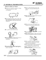
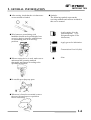
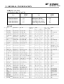
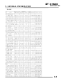
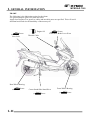
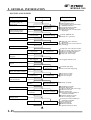
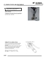
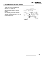
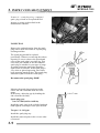
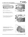
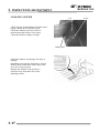
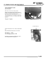
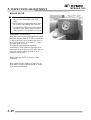
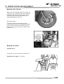
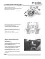
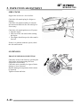
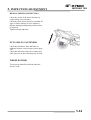
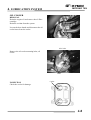
1
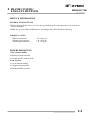
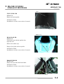
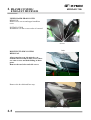
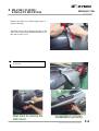
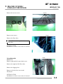
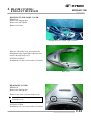
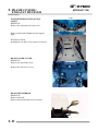
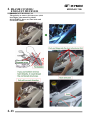
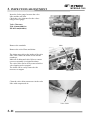
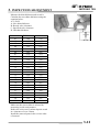
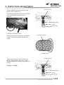
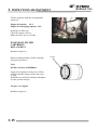
MYROAD 700i By KWANG YANG Motor Co., Ltd. First Edition, FEB. 2011 All rights reserved. Any reproduction or unauthorized use without the written permission of KWANG YANG Motor Co., Ltd. is expressly prohibited. 4122-KKE5-S00 MYROAD 700i PREFACE This Service Manual describes the technical features and servicing procedures for the KYMCO XCITING 700. TABLE OF CONTENTS 1 FRAME COVERS /EXHAUST MUFFLER 2 Section 1 contains the precautions for all operations stated in this manual. Read them carefully before any operation is started. INSPECTION/ADJUSTMENT 3 LUBRICATION SYSTEM 4 CABLE & HARNESS ROUTING 5 Section 2 is the removal/installation procedures for the frame covers which are subject to higher removal/installation frequency during maintenance and servicing operations. AFI (AUTOMATIC FUEL INJECTION) 6 COOLING SYSTEM 7 ENGINE REMOVAL/INSTALLATION 8 CYLINDER HEAD/VALVES 9 CYLINDER/PISTON 10 DRIVE AND DRIVEN PULLEY 11 FINAL REDUCTION 12 Section 3 describes the inspection/ adjustment procedures, safety rules and service information for each part, starting from periodic maintenance. The information and contents included in this manual may be different from the motorcycle in case specifications are changed. KYMCO reserves the right to make changes at any time without notice and without incurring any obligation. KWANG YANG MOTOR CO., LTD. OVERSEAS SALES DEPARTMENT OVERSEAS SERVICE SECTION ELECTRICAL EQUIPMENT Most sections start with an assembly or system illustration and troubleshooting for the section. The subsequent pages give detailed procedures for the section. A.C. GENEARTOR/STARTER CLUTCH 13 CHASSIS Sections 8 through 14 give instructions for disassembly, assembly and adjustment of engine parts. Section 15 through 17 is the removal/ installation of chassis. Section 18 through 21 states the testing and measuring methods of electrical equipment. ENGINE GENERAL INFORMATION CRANKCASE/CRANKSHAFT 14 STEERING HANDLEBAR/FRONT WHEEL/FRONT SHOCK ABSORBER 15 REAR FORK/REAR WHEEL/REAR SHOCK ABSORBER` 16 BRAKE SYSTEM 17 BATTERY/CHARGING SYSTEM 18 IGNITION SYSTEM 19 ELECTRIC STARTER 20 LIGHTS/METERS/SWITCHES 21 ANTI-LOCK BRAKE SYSTEM(ABS) 22 1. GENERAL INFORMATION MYROAD 700i 1 1 __________________________________________________________________________________ __________________________________________________________________________________ __________________________________________________________________________________ __________________________________________________________________________________ __________________________________________________________________________________ GENERAL INFORMATION __________________________________________________________________________________ SERIAL NUMBER----------------------------------------------------------- 1 - 1 SPECIFICATIONS --------------------------------------------------------- 1 - 2 SERVICE PRECAUTIONS ------------------------------------------------- 1 - 3 TORQUE VALUES ---------------------------------------------------------- 1 - 7 SPECIAL TOOLS ------------------------------------------------------------ 1 - 9 LUBRICATION POINTS --------------------------------------------------- 1-10 TROUBLESHOOTING------------------------------------------------------ 1-12 1-0 1. GENERAL INFORMATION MYROAD 700i SERIAL NUMBER FRAME NUMBER(VIN): VEHICLE IDENTIFICATION NUMBER(VIN): Location of Engine Serial Number 1-1 1. GENERAL INFORMATION MYROAD 700i SPECIFICATIONS Displacement Fuel Used Dry weight Tires Front wheel Rear wheel Total Front wheel Rear wheel Total Front wheel Rear wheel Ground clearance Min. turning radius Bore x stroke Compression ratio Lubrication type Lubrication System Oil pump type Oil filter type 10.5:1 13 kgf/cm² 7° BTDC 40° ABDC 40° BBDC 10° ATDC 0.16 mm 0.22 mm Rpm Forced pressure & Wet sump Trochoid Full-flow filtration 3L DR8E Ignition timing ECU Spark plug gap Battery Capacity Clutch Type 0.6~0.7 mm 12V12AH Dry, centrifugal automatic Type Helical gear/spur gear Operation Automatic centrifugal Type Type CVT Preliminary Final FR/RR tire rolling circumference 0.99 5.58 Tire pressure Front (rider only/60 kg) Rear Turning angle Brake system type Damping Device Engine Compression pressure Open Intake valve Close Open Exhaust valve Close Valve clearance Intake Exhaust (cold) Idle speed Gasoline, 4-stroke Twin cylinder ROOF O.H.C. 76.9X75.3 mm Moving Device Starting system Type Cylinder arrangement Combustion chamber type Valve arrangement 108 kg 160 kg 268 kg 116 kg 168 kg 284 kg 120/70-R15 160/60-R14 135 mm 2700 mm Electric starter motor Spark plug Transmis- Reduction sion Gear Ratio Curb weight 92# nonleaded gasoline 14 L Fuel capacity Throttle Body Venturi φ 38 mm dia Full transistor ignition Type Ignition System Name Overall length Overall width Overall height Wheel base Engine type SPECIFICATIONS MYROAD 700i 2330 mm 830 mm 1510 mm 1615 mm D.O.H.C. 699.5 cc Fuel System Electrical EquipmentPower Drive System ITEM ITEM SPECIFICATIONS Air cleaner type & No Wet paper type element Suspension type Frame type mm 2 kg/cm² 2.25 kg/cm² Left 40° Right 40° Rear Disk brake Front Disk brake Front Telescopic fork Rear Unit swing Double cradle Oil capacity Final reduction oil 0.4 L capacity Cooling Type Liquid cooled 1-2 1. GENERAL INFORMATION MYROAD 700i SERVICE PRECAUTIONS Make sure to install new gaskets, O-rings, circlips, cotter pins, etc. when reassembling. Apply or add designated greases and lubricants to the specified lubrication points. After reassembly, check all parts for proper tightening and operation. When tightening bolts or nuts, begin with larger-diameter to smaller ones at several times, and tighten to the specified torque diagonally. When two persons work together, pay attention to the mutual working safety. Use genuine parts and lubricants. Disconnect the battery negative (-) terminal before operation. When using a spanner or other tools, make sure not to damage the motorcycle surface. When servicing the motorcycle, be sure to use special tools for removal and installation. After disassembly, clean removed parts. Lubricate sliding surfaces with engine oil before reassembly. 1-3 After operation, check all connecting points, fasteners, and lines for proper connection and installation. When connecting the battery, the positive (+) terminal must be connected first. After connection, apply grease to the battery terminals. Terminal caps shall be installed securely. 1. GENERAL INFORMATION If the fuse is burned out, find the cause and repair it. Replace it with a new one according to the specified capacity. Confirm Capacity MYROAD 700i The connector shall be inserted completely. If the double connector has a lock, lock it at the correct position. Check if there is any loose wire. After operation, terminal caps shall be installed securely. Before connecting a terminal, check for damaged terminal cover or loose negative terminal. When taking out the connector, the lock on the connector shall be released before operation. Check the double connector cover for proper coverage and installation. Hold the connector body when connecting or disconnecting it. Do not pull the connector wire. Insert the terminal completely. Check the terminal cover for proper coverage. Do not make the terminal cover opening face up. Check if any connector terminal is bending, protruding or loose. Secure wire harnesses to the frame with their respective wire bands at the designated locations. Tighten the bands so that only the insulated surfaces contact the wire harnesses. 1-4 1. GENERAL INFORMATION After clamping, check each wire to make sure it is secure. MYROAD 700i Route harnesses so they are neither pulled tight nor have excessive slack. Do not pull too tight! Do not squeeze wires against the weld or its clamp. Protect wires and harnesses with electrical tape or tube if they contact a sharp edge or corner. After clamping, check each harness to make sure that it is not interfering with any moving or sliding parts. When rubber protecting cover is used to protect the wire harnesses, it shall be installed securely. When fixing the wire harnesses, do not make it contact the parts which will generate high heat. Do not break the sheath of wire. If a wire or harness is with a broken sheath, repair by wrapping it with protective tape or replace it. Route wire harnesses to avoid sharp edges or corners. Avoid the projected ends of bolts and screws. Route wire harnesses passing through the side of bolts and screws. Avoid the projected ends of bolts and screws. When installing other parts, do not press or squeeze the wires. Do not press or squeeze the i 1-5 1. GENERAL INFORMATION After routing, check that the wire harnesses are not twisted or kinked. Wire harnesses routed along with handlebar should not be pulled tight, have excessive slack or interfere with adjacent or surrounding parts in all steering positions. MYROAD 700i Symbols: The following symbols represent the servicing methods and cautions included in this service manual. Engine Oil : Apply engine oil to the specified points. (Use designated engine oil for lubrication.) : Apply grease for lubrication. Grease : Transmission Gear Oil (90#) Gear Oil When a testing device is used, make sure to understand the operating methods thoroughly and operate according to the operating instructions. * : Note Do you understand the instrument? Be careful not to drop any parts. When rust is found on a terminal, remove the rust with sand paper or equivalent before connecting. Remove Rust! 1-6 1. GENERAL INFORMATION MYROAD 700i TORQUE VALUES STANDARD TORQUE VALUES Item 5mm bolt and nut 6mm bolt and nut 8mm bolt and nut 10mm bolt and nut 12mm bolt and nut Torque Kg-m 0.5 1.0 2.2 3.5 5.5 Item 5mm screw 6mm screw, SH bolt 6mm flange bolt and nut 8mm flange bolt and nut 10mm flange bolt and nut Torque specifications listed below are for important fasteners. ENGINE 1-7 Torque Kgf-m 0.4 0.9 1.2 2.7 4.0 1. GENERAL INFORMATION MYROAD 700i FRAME 1-8 1. GENERAL INFORMATION MYROAD 700i SPECIAL TOOLS Tool Name Tool No. Remarks Lock nut socket wrench A120F00007 Steering stem removal or install Oil seal & bearing installers A120E00014 Oil seal & bearing install Universal holder A120E00017 Holding clutch for removal Flywheel holder A120E00021 A.C. generator flywheel holding Bearing pullers A120E00030 Bearing removal Tappet adjuster A120E00036 Tappet adjustment Bearing pullers A120E00037 Bearing removal Valve spring compressor A120E00040 Valve removal Oil filter cartridge wrench A120E00052 Cartridge removal or install Clutch spring compressor A120E00053 Clutch disassembly Flywheel puller A120E00061 A.C. generator flywheel removal Clutch fixed bolt A120E00038 Clutch Balancer gear nut wrench A120F00080 Balancer gear Connecting rod bolts wrench A120F00081 Connecting rod 1-9 1. GENERAL INFORMATION MYROAD 700i LUBRICATION POINTS ENGINE Lubrication Points Lubricant Valve guide/valve stem movable part Camshaft protruding surface Valve rocker arm friction surface Camshaft drive chain Cylinder lock bolt and nut Piston surroundings and piston ring grooves Piston pin surroundings Cylinder inside wall Connecting rod/piston pin hole Connecting rod big end Crankshaft Balancer shaft Crankshaft one-way clutch movable part Oil pump drive chain Starter reduction gear engaging part O-ring face Oil seal lip •Genuine KYMCO Engine Oil (SAE 5W-50) •API SJ Engine Oil Drive gear shaft Countershaft Final gear Final gear shaft Transmission oil: SAE 90 Transmission gearshaft bearing part A.C. generator connector Adhesive 1-10 1. GENERAL INFORMATION MYROAD 700i FRAME The following is the lubrication points for the frame. Use general purpose grease for parts not listed. Apply clean engine oil or grease to cables and movable parts not specified. This will avoid abnormal noise and rise the durability of the motorcycle. Engine Oil Grease Seat Lock Throttle Cable Grease Front/Rear Brake Lever Pivot Rear Wheel Bearing Grease Center Stand/Side Stand Pivot Grease 1-11 Front Wheel Bearing Grease 1. GENERAL INFORMATION MYROAD 700i TROUBLESHOOTING ENGINE WILL NOT START OR IS HARD TO START Inspection/Adjustment Probable Cause Symptom Check if fuel reaches carburetor by loosening drain screw Fuel reaches carburetor/fuel injector Fuel does not reach carburetor/fuel injector Remove spark plug and install it into spark plug cap to test spark by connecting it to engine ground Spark jumps Weak or no spark Test cylinder compression Normal compression Low or no compression cEmpty fuel tank dClogged carburetor fuel inlet tube, vacuum tube or fuel tube eClogged auto fuel valve fClogged float oil passage gClogged fuel tank cap breather hole hClogged fuel strainer iClogged fuel filter jFaulty fuel pump cFaulty spark plug dFouled spark plug eFaulty ignition unit fFaulty A.C. generator gBroken or shorted ignition coil hBroken or shorted exciter coil iFaulty ignition switch cStarter motor idles but crankshaft does not rotate dValve clearance too small eImproper valve and seat contact fWorn cylinder and piston rings gBlown cylinder head gasket hFlaws in cylinder head iSeized valve jImproper valve timing Start engine by follow-ing normal starting procedure Engine does not fire Engine fires but does not start Dry spark plug Wet spark plug cFaulty auto bystarter dAir leaking through intake pipe eIncorrect ignition timing fIncorrectly adjusted pilot screw Remove spark plug and inspect again cFlooded carburetor dFaulty auto bystarter eThrottle valve excessively open 1-12 1. GENERAL INFORMATION MYROAD 700i ENGINE LACKS POWER Inspection/Adjustment Probable Cause Symptom Start engine and accelerate lightly for observation Engine speed increases Engine speed does not increase sufficiently Check ignition timing (using a timing light) cClogged air cleaner dRestricted fuel flow eClogged fuel line between fuel tank and carburetor fClogged exhaust muffler gFaulty auto bystarter hSplit carburetor vacuum piston diaphragm cFaulty ignition unit dFaulty A.C. generator Correct timing Incorrect timing Correct Incorrect cImproper valve clearance adjustment dWorn valve seat (valve stem too protruding Normal compression Abnormal compression cImproper valve and seat contact dWorn cylinder and piston rings eBlown cylinder head gasket fFlaws in cylinder head gImproper valve timing Check valve clearance Test cylinder compression Check carburetor for clogging Not Clogged Clogged cClogged carburetor jets Remove spark plug and inspect Plug not fouled or discolored Plug fouled or discolored Correct and not contaminated Incorrect or contaminated Remove oil dipstick and check oil level and condition cFouled spark plug dIncorrect heat range plug cOil level too high dOil level too low eOil not changed Remove cylinder head bolts and inspect Valve train lubricated properly Valve train not lubricated properly Check if engine overheats Engine does not overheats Engine overheats Rapidly accelerate or run at high speed Engine does not knock 1-13 Engine knocks cFaulty oil pump cInsufficient coolant dFaulty thermostat eWorn cylinder and piston rings fMixture too lean gPoor quality fuel hExcessive carbon buildup in combustion chamber iIgnition timing too early jAir in cooling system cExcessive carbon build-up in combustion chamber dPoor quality fuel eClutch slipping fMixture too lean g Ignition timing too early 1. GENERAL INFORMATION MYROAD 700i POOR PERFORMANCE (ESPECIALLY AT IDLE AND LOW SPEEDS) Inspection/Adjustment Symptom Probable Cause Check ignition timing cFaulty ignition unit dFaulty A.C. generator Correct timing Incorrect timing Correctly adjusted Incorrectly adjusted cMixture too rich (turn screw out) dMixture too lean (turn screw in) Air leaks cDamaged insulator rubber dCarburetor not securely tightened eFaulty intake manifold gasket fDeformed carburetor O-ring Check carburetor pilot screw adjustment Check intake manifold for air leaks No air leak Remove spark plug and install it into spark plug cap to test spark by connecting it to engine ground Good spark Weak or intermittent spark cFaulty or fouled spark plug dFaulty ignition unit eFaulty A.C. generator fFaulty ignition coil gBroken or shorted high tension wire hFaulty ignition switch Good Faulty cDamaged air cut-off valve diaphragm dDamaged air cut-off valve spring Check carburetor air cut-off valve 1-14 1. GENERAL INFORMATION MYROAD 700i POOR PERFORMANCE (AT HIGH SPEED) Inspection/Adjustment Symptom Probable Cause Check ignition timing cFaulty ignition unit dFaulty A.C. generator Correct timing Incorrect timing Correctly adjusted Incorrectly adjusted cImproperly adjusted valve clearance dWorn valve seat Fuel flows freely Fuel flow restricted cEmpty fuel tank dClogged fuel tube or filter eFaulty fuel pump fCracked fuel pump vacuum tube Not clogged Clogged cClean and unclog Correct Incorrect cCam timing gear aligning marks not aligned Not weakened Weak spring Check valve clearance Check fuel pump for fuel supply Check carburetor jets for clogging Check valve timing Check valve spring tension 1-15 cFaulty spring 1. GENERAL INFORMATION MYROAD 700i ENGINE NOISE Symptom Valve noise Probable Cause cValve clearance too large dWorn camshaft lobe cWorn piston rings Piston noise Cam chain noise Crankshaft noise dWorn piston pin and connecting rod small end eExcessive carbon build-up in combustion chamber cDamaged cam chain tensioner dWorn cam gear teeth eWorn or damaged cam chain fExtended cam chain cFaulty crankshaft bearing dWorn crank pin bearing Gear noise cWorn or damaged final reduction gears dWorn final reduction gear shaft splines 1-16 1. GENERAL INFORMATION MYROAD 700i CLUTCH, DRIVE AND DRIVEN PULLEYS Symptom Engine starts but motor-cycle does not Motorcycle creeps or engine starts but soon stops or seems to rush out (Rear wheel rotates when engine idles) 1-17 Probable Cause cWorn or slipping drive belt dBroken ramp plate eBroken drive face spring fSeparated clutch lining gDamaged driven pulley shaft splines hDamaged final gear iSeized final gear cBroken shoe spring dClutch outer and clutch weight stuck eSeized pivot Engine lacks power at start of a grade(poor slope performance) cWorn or slipping drive belt dWorn weight rollers eSeized drive pulley bearings fWeak driven face spring gWorn or seized driven pulley bearings Engine lacks power at high speed cWorn or slipping drive belt dWorn weight rollers eWorn or seized driven pulley bearings There is abnormal noise or smell while running cOil or grease fouled drive belt dWorn drive belt eWeak driven face spring fWorn or seized driven pulley bearings 1. GENERAL INFORMATION MYROAD 700i STARTER MOTOR 1. Starter motor won‘t turn Symptom Inspection/Adjustment Probable Cause Check operation of stop switch by applying brake Stoplight comes on Stoplight does not come on Signals operate properly Signals dim, remain on or don‘t operate Relay operates properly Relay does not operate Starter motor turns Starter does not turn Check battery circuit by operating turn signals Check operation of starter relay by depressing starter button Connect starter motor directly to battery cBurned out fuse dWeak or dead battery eFaulty stop switch fLoose or disconnected connectors gBroken or shorted ignition switch wire hFaulty side stand switch cFaulty or weak battery cPoor starter button connection dOpen or shorted starter relay eLoose or disconnected connectors cWorn brushes dOpen or shorted wires or rotor eOpen starter motor cable fLoose connectors cOpen wire harness 2. Starter motor turns slowly or idles Symptom Inspection/Adjustment Probable Cause Check battery circuit by operating turn signals Signals operate properly Signals dim, remain on or don‘t operate Starter motor turns slowly Starter motor turns normally cWeak or dead battery Connect starter motor directly to battery cLoose connector or terminal dPoor contact in starter relay eFaulty starter clutch Rotate crankshaft Hard to turn Turns easily cSeized cylinder cBroken or shorted starter motor cable 3. Starter motor does not stop turning Symptom Inspection/Adjustment Probable Cause Turn ignition switch OFF Not stopped Stopped cFaulty starter pinion cStarter relay shorted or stuck closed 1-18 1. GENERAL INFORMATION MYROAD 700i NO SPARK AT SPARK PLUG Inspection/Adjustment Symptom Probable Cause Replace with a new spark plug and inspect again Good spark cFaulty spark plug Not loose Loose cFaulty spark plug Good Good cPoorly connected coupler Normal Abnormal Normal Abnormal Weak or no spark Check spark plug cap and high-tension wire for looseness Check ignition unit coupler for looseness Measure resistance between terminals of ignition unit coupler Check related parts cFaulty ignition switch dFaulty exciter coil eFaulty pulser coil fFaulty ignition coil cBroken wire harness dPoorly connected coupler Check ignition unit Abnormal 1-19 cFaulty ignition unit 1. GENERAL INFORMATION MYROAD 700i POOR CHARGING (BATTERY OVER DISCHARGING OR OVERCHARGING) Undercharging Inspection/Adjustment Symptom Probable Cause Start engine and test limit voltage of battery terminals Normal voltage Voltage does not increase Normal Resistance too low cFaulty AC generator dFaulty regulator/rectifier eFaulty battery Measure resistance between AC generator coil terminals cShorted AC generator coil dOpen circuit between AC generator 3 yellow wires Test output voltage of regulator/rectifier coupler red wire Normal voltage No voltage cFaulty regulator/rectifier dFaulty AC generator eLoose regulator/rectifier coupler fLimit voltage too high Overcharging Inspection/Adjustment Symptom Probable Cause Measure battery limit voltage with an electric tester Normal Abnormal cFaulty battery dFaulty regulator/rectifier eBroken or poorly connected regulator/rectifier black wire Abnormal cLimit voltage too high Check resistance between regulator/ rectifier terminals Normal 1-20 1. GENERAL INFORMATION MYROAD 700i FUEL GAUGE 1. Pointer does not register correctly (Ignition switch ON) Probable Cause Symptom Inspection/Adjustment Check battery circuit by operating turn signals Remove fuel unit and check operation of pointer by moving float up and down Float up: Full Float down: Empty Check operation of pointer by opening and shorting fuel unit terminal on wire harness side cBurned out fuse dWeak or dead battery eFaulty ignition switch fLoose or disconnected connectors gBroken wire harness Signals operate properly Signals dim, remain on or don‘t operate Pointer does not move Pointer moves cFaulty float Pointer moves cBroken or shorted fuel unit wire Pointer does not move Check connectors for proper connection Faulty Good cDisconnected connector dIncorrectly connected connector eBroken or shorted wire in fuel gauge 2. Pointer fluctuates or swings (Ignition switch ON) Probable Cause Symptom Inspection/Adjustment Check battery circuit by operating turn signals and horn Remove fuel unit and check operation of pointer by moving float up and down Move float up and down rapidly (1 round /sec.) to check the operation of pointer Signals operate properly Signals dim, remain on or don‘t operate Pointer moves Pointer does not move Pointer moves in accordance with float Pointer does not move in accord-ance with cBurned out fuse dWeak or dead battery eFaulty ignition switch fLoose or disconnected connector gBroken wire harness cPoor contact in fuel unit cInsufficient damping oil in fuel gauge Check connectors for proper connection. Good 1-21 Faulty cLoose or disconnected connector cBroken or shorted wire in fuel gauge 1. GENERAL INFORMATION MYROAD 700i STEERING HANDLEBAR DOES NOT TRACK STRAIGHT Symptom Probable Cause (Front and rear tire pressures are normal) Steering is heavy cSteering stem nut too tight dBroken steering steel balls Front or rear wheel is wobbling cExcessive wheel bearing play dBent rim eLoose axle nut Steering handlebar pulls to one side cMisaligned front and rear wheels dBent front fork POOR SUSPENSION PERFORMANCE Symptom Suspension is too soft Probable Cause (Front and rear tire pressures are normal) cWeak shock spring dExcessive load eShock damper oil leaking Suspension is too hard cBent fork tube or shock rod Suspension is noisy cFork tube and slider binding dFork spring and slider binding eDamaged shock stopper rubber fLoose steering stem nut POOR BRAKE PERFORMANCE Symptom Probable Cause Soft brake lever cWorn brake linings dForeign matter on brake linings eRough brake drum contacting area Hard brake lever cWorn brake linings dForeign matter on brake linings eRough brake drum contacting area Hard to brake cWorn brake linings dWorn brake cam contacting area on Poor brake performance cWorn brake linings dForeign matter on brake linings Brake squeaks cSluggish or elongated brake cables dBrake shoes improperly contact eWater and mud in brake system fOil or grease on brake linings 1-22 1. GENERAL INFORMATION MYROAD 700i TROUBLESHOOTING (XCITING 250 AFI) ENGINE WILL NOT START OR IS HARD TO START Inspection/Adjustment Probable Cause Symptom 1. Make sure engine stop switch is ON. 2. Put the side stand up. 3. Connect the diagnostic tool, then check EMS and correct problems. Fuel reaches fuel injector Fuel does not reach fuel injector cEmpty fuel tank dClogged fuel pump filter eFaulty fuel pump fFaulty fuel cut-off relay gCracked fuel hose Weak or no spark cFaulty spark plug dFouled spark plug eFaulty ignition coil fFaulty CPS gBroken or shorted ignition coil hBroken or shorted CPS iFaulty ignition switch No fuel supply cFaulty fuel injector dClogged fuel injector eFaulty ECU Remove spark plug and install it into spark plug cap to test spark by connecting it to engine ground Spark jumps Remove the fuel injector, start the starter motor to check fuel injector operation. Fuel supply Test cylinder compression Normal compression 1-23 Low or no compression cStarter motor idles but crankshaft does not rotate dValve clearance too small eImproper valve and seat contact fWorn cylinder and piston rings gBlown cylinder head gasket hFlaws in cylinder head iSeized valve jImproper valve timing 1. GENERAL INFORMATION MYROAD 700i ENGINE LACKS POWER Inspection/Adjustment Probable Cause Symptom Connect the diagnostic tool, then check EMS and correct problems. Start engine and accelerate lightly for observation Engine speed increases Check ignition timing Engine speed does not increase sufficiently cClogged air cleaner dClogged exhaust muffler eFaulty spark plug fFaulty throttle gFaulty fuel pump hFaulty fuel injector iImproper valve timing jLow or no compression cFaulty ECU dFaulty CPS Correct timing Incorrect timing Correct Incorrect cImproper valve clearance adjustment dWorn valve seat (valve stem too protruding Normal compression Abnormal compression cImproper valve and seat contact dWorn cylinder and piston rings eBlown cylinder head gasket fFlaws in cylinder head gImproper valve timing Check valve clearance Test cylinder compression Check fuel injector for clogging Not Clogged Clogged cFouled fuel injector Remove spark plug and inspect Plug not fouled or discolored Plug fouled or discolored Correct and not contaminated Incorrect or contaminated Remove oil dipstick and check oil level and condition cFouled spark plug dIncorrect heat range plug cOil level too high dOil level too low eOil not changed Remove cylinder head bolts and inspect Valve train lubricated properly Valve train not lubricated properly Check if engine overheats Engine does not overheats Engine overheats cFaulty oil pump cInsufficient coolant dFaulty thermostat eWorn cylinder and piston rings fMixture too lean gPoor quality fuel hExcessive carbon buildup in combustion chamber iIgnition timing too early jAir in cooling system 1-24 1. GENERAL INFORMATION MYROAD 700i Rapidly accelerate or run at high speed Engine does not knock 1-25 Engine knocks cExcessive carbon build-up in combustion chamber dPoor quality fuel eClutch slipping fIgnition timing too early 1. GENERAL INFORMATION MYROAD 700i POOR PERFORMANCE (ESPECIALLY AT IDLE AND LOW SPEEDS) Inspection/Adjustment Symptom Probable Cause Connect the diagnostic tool, then check EMS and correct problems. Check ignition timing Correct timing Incorrect timing Not Clogged Clogged cFaulty ignition coil dFaulty CPS eFaulty ECU Check fuel injector for clogging cFouled fuel injector dFaulty fuel pump Check intake manifold for air leaks No air leak Air leaks cDamage insulator rubber dThrottle body not securely tighten eFaulty intake manifold O-ring Remove spark plug and install it into spark plug cap to test spark by connecting it to engine ground Good spark Weak or intermittent spark cFaulty CPS dFaulty ignition coil eBroken or shorted high tension wire fFaulty spark plug Check throttle body Good Faulty cFouled throttle body dFaulty TPI reset 1-26 1. GENERAL INFORMATION MYROAD 700i POOR PERFORMANCE (AT HIGH SPEED) Inspection/Adjustment Symptom Probable Cause Connect the diagnostic tool, then check EMS and correct problems. Check ignition timing Correct timing Incorrect timing cFaulty spark plug dFaulty ignition coil eFaulty CPS Check valve clearance cImproperly adjusted valve Correctly adjusted Incorrectly adjusted clearance dWorn valve seat Check fuel pump for fuel supply Fuel flows freely Fuel flow restricted Not clogged Clogged Correct Incorrect Not weakened Weak spring cEmpty fuel tank dClogged fuel hose or filter eFaulty fuel pump fClogged fuel injector Check throttle body or air cleaner for clogging cClean and unclog Check valve timing cCam timing gear aligning marks not aligned Check valve spring tension 1-27 cFaulty spring 1. GENERAL INFORMATION MYROAD 700i ENGINE NOISE Symptom Valve noise Probable Cause cValve clearance too large dWorn camshaft lobe cWorn piston rings Piston noise Cam chain noise Crankshaft noise dWorn piston pin and connecting rod small end eExcessive carbon build-up in combustion chamber cDamaged cam chain tensioner dWorn cam gear teeth eWorn or damaged cam chain fExtended cam chain cFaulty crankshaft bearing dWorn crank pin bearing Gear noise cWorn or damaged final reduction gears dWorn final reduction gear shaft splines 1-28 1. GENERAL INFORMATION MYROAD 700i CLUTCH, DRIVE AND DRIVEN PULLEYS Symptom Engine starts but motor-cycle does not Motorcycle creeps or engine starts but soon stops or seems to rush out (Rear wheel rotates when engine idles) 1-29 Probable Cause cWorn or slipping drive belt dBroken ramp plate eBroken drive face spring fSeparated clutch lining gDamaged driven pulley shaft splines hDamaged final gear iSeized final gear cBroken shoe spring dClutch outer and clutch weight stuck eSeized pivot Engine lacks power at start of a grade(poor slope performance) cWorn or slipping drive belt dWorn weight rollers eSeized drive pulley bearings fWeak driven face spring gWorn or seized driven pulley bearings Engine lacks power at high speed cWorn or slipping drive belt dWorn weight rollers eWorn or seized driven pulley bearings There is abnormal noise or smell while running cOil or grease fouled drive belt dWorn drive belt eWeak driven face spring fWorn or seized driven pulley bearings 1. GENERAL INFORMATION MYROAD 700i STARTER MOTOR 1. Starter motor won‘t turn Symptom Inspection/Adjustment Probable Cause Check operation of stop switch by applying brake Stoplight comes on Stoplight does not come on Signals operate properly Signals dim, remain on or don‘t operate Relay operates properly Relay does not operate Starter motor turns Starter does not turn Check battery circuit by operating turn signals Check operation of starter relay by depressing starter button Connect starter motor directly to battery cBurned out fuse dWeak or dead battery eFaulty stop switch fLoose or disconnected connectors gBroken or shorted ignition switch wire hFaulty side stand switch cFaulty or weak battery cPoor starter button connection dOpen or shorted starter relay eLoose or disconnected connectors cWorn brushes dOpen or shorted wires or rotor eOpen starter motor cable fLoose connectors cOpen wire harness 2. Starter motor turns slowly or idles Symptom Inspection/Adjustment Probable Cause Check battery circuit by operating turn signals Signals operate properly Signals dim, remain on or don‘t operate Starter motor turns slowly Starter motor turns normally cWeak or dead battery Connect starter motor directly to battery cLoose connector or terminal dPoor contact in starter relay eFaulty starter clutch Rotate crankshaft Hard to turn Turns easily cSeized cylinder cBroken or shorted starter motor cable 3. Starter motor does not stop turning Symptom Inspection/Adjustment Probable Cause Turn ignition switch OFF Not stopped Stopped cFaulty starter pinion cStarter relay shorted or stuck 1-30 1. GENERAL INFORMATION MYROAD 700i closed NO SPARK AT SPARK PLUG Inspection/Adjustment Symptom Probable Cause Connect the diagnostic tool, then check EMS and correct problems. Replace with a new spark plug and inspect again Good spark cFaulty spark plug Not loose Loose cFaulty spark plug Good Good cPoorly connected coupler Normal Abnormal Normal Abnormal Weak or no spark Check spark plug cap and high-tension wire for looseness Check ignition unit coupler for looseness Measure resistance between terminals of ignition unit coupler Check related parts cFaulty ignition switch dFaulty CPS eFaulty ignition coil cBroken wire harness dPoorly connected coupler Check ignition coil Abnormal 1-31 cFaulty ignition coil 1. GENERAL INFORMATION MYROAD 700i POOR CHARGING (BATTERY OVER DISCHARGING OR OVERCHARGING) Undercharging Inspection/Adjustment Symptom Probable Cause Start engine and test limit voltage of battery terminals Normal voltage Voltage does not increase Normal Resistance too low cFaulty AC generator dFaulty regulator/rectifier eFaulty battery Measure resistance between AC generator coil terminals cShorted AC generator coil dOpen circuit between AC generator 3 yellow wires Test output voltage of regulator/rectifier coupler red wire Normal voltage No voltage cFaulty regulator/rectifier dFaulty AC generator eLoose regulator/rectifier coupler fLimit voltage too high Overcharging Inspection/Adjustment Symptom Probable Cause Measure battery limit voltage with an electric tester Normal Abnormal cFaulty battery dFaulty regulator/rectifier eBroken or poorly connected regulator/rectifier black wire Abnormal cLimit voltage too high Check resistance between regulator/ rectifier terminals Normal 1-32 1. GENERAL INFORMATION MYROAD 700i FUEL GAUGE 1. Pointer does not register correctly (Ignition switch ON) Probable Cause Symptom Inspection/Adjustment Check battery circuit by operating turn signals Remove fuel unit and check operation of pointer by moving float up and down Float up: Full Float down: Empty Check operation of pointer by opening and shorting fuel unit terminal on wire harness side cBurned out fuse dWeak or dead battery eFaulty ignition switch fLoose or disconnected connectors gBroken wire harness Signals operate properly Signals dim, remain on or don‘t operate Pointer does not move Pointer moves cFaulty float Pointer moves cBroken or shorted fuel unit wire Pointer does not move Check connectors for proper connection Faulty Good cDisconnected connector dIncorrectly connected connector eBroken or shorted wire in fuel gauge 2. Pointer fluctuates or swings (Ignition switch ON) Symptom Inspection/Adjustment Probable Cause Check battery circuit by operating turn signals and horn Remove fuel unit and check operation of pointer by moving float up and down Move float up and down rapidly (1 round /sec.) to check the operation of pointer Signals operate properly Signals dim, remain on or don‘t operate Pointer moves Pointer does not move Pointer moves in accordance with float Pointer does not move in accord-ance with cBurned out fuse dWeak or dead battery eFaulty ignition switch fLoose or disconnected connector gBroken wire harness cPoor contact in fuel unit cInsufficient damping oil in fuel gauge Check connectors for proper connection. Good 1-33 Faulty cLoose or disconnected connector cBroken or shorted wire in 1. GENERAL INFORMATION MYROAD 700i fuel gauge STEERING HANDLEBAR DOES NOT TRACK STRAIGHT Symptom Probable Cause (Front and rear tire pressures are normal) Steering is heavy cSteering stem nut too tight dBroken steering steel balls Front or rear wheel is wobbling cExcessive wheel bearing play dBent rim eLoose axle nut Steering handlebar pulls to one side cMisaligned front and rear wheels dBent front fork POOR SUSPENSION PERFORMANCE Symptom Suspension is too soft Probable Cause (Front and rear tire pressures are normal) cWeak shock spring dExcessive load eShock damper oil leaking Suspension is too hard cBent fork tube or shock rod Suspension is noisy cFork tube and slider binding dFork spring and slider binding eDamaged shock stopper rubber fLoose steering stem nut POOR BRAKE PERFORMANCE Symptom Probable Cause Soft brake lever cWorn brake linings dForeign matter on brake linings eRough brake drum contacting area Hard brake lever cWorn brake linings dForeign matter on brake linings eRough brake drum contacting area Hard to brake cWorn brake linings dWorn brake cam contacting area on Poor brake performance cWorn brake linings dForeign matter on brake linings Brake squeaks cSluggish or elongated brake cables dBrake shoes improperly contact eWater and mud in brake system fOil or grease on brake linings 1-34 1. GENERAL INFORMATION 1-35 MYROAD 700i 2. FRAME COVERS/ EXHAUST MUFFLER MYROAD 700i 2 __________________________________________________________________________________ 2 __________________________________________________________________________________ __________________________________________________________________________________ __________________________________________________________________________________ __________________________________________________________________________________ FRAME COVERS/EXHAUST MUFFLER __________________________________________________________________________________ SCHEMATIC DRAWING ------------------------------------------------- 2- 1 SERVICE INFORMATION------------------------------------------------ 2- 2 TROUBLESHOOTING----------------------------------------------------- 2- 2 FRAME COVERS REMOVAL ------------------------------------------- 2- 3 EXHAUST MUFFLER ----------------------------------------------------- 2-17 2-0 2. FRAME COVERS/ EXHAUST MUFFLER SCHEMATIC DRAWING 2-1 MYROAD 700i 2. FRAME COVERS/ EXHAUST MUFFLER MYROAD 700i SERVICE INFORMATION GENERAL INSTRUCTIONS • When removing frame covers, use care not to pull them by force because the cover joint claws may be damaged. • Make sure to route cables and harnesses according to the Cable & Harness Routing. TORQUE VALUES Muffler mount bolt Exhaust pipe joint nut Exhaust pipe band bolt 3.2~3.8 kg-m 1.0~1.4 kg-m 1.0~1.4 kg-m TROUBLESHOOTING Noisy exhaust muffler • Damaged exhaust muffler • Exhaust muffler joint air leaks Lack of power • Caved exhaust muffler • Clogged exhaust muffler • Exhaust muffler air leaks 2-2 2. FRAME COVERS/ MYROAD 700i EXHAUST MUFFLER FRAME COVERS REMOVAL Nuts Damper Unit SEAT REMOVAL Unlock the seat with the ignition key. Open the seat. Remove the two nuts and seat damper unit. Remove the two nuts and the seat. INSTALLATION Installation is in the reverse order of the removal. Nuts After installation, check the seat installation by moving the seat. Nuts LUGGAGE BOX REMOVAL After removal the seat, side cover, carrier, body cover, then you can remove the luggage box. Screws Bolts Remove the screws and bolts. Accessory Socket Connector Raise the luggage box, disconnect the luggage box light and accessory socket connectors. INSTALLATION Installation is in the reverse order of removal. Luggage box light Connector 2-3 2. FRAME COVERS/ MYROAD 700i EXHAUST MUFFLER Bolt FUEL PUMP LID REMOVAL Remove the bolt and lid. INSTALLATION Installation is in the reverse order of removal. Fuel pump Lid Rubber Cap REAR SPOILER REMOVAL Unlock the seat with the ignition key. Open the seat. Remove the rubber cap. Remove four bolts and rear spoiler. INSTALLATION Installation is in the reverse order of removal. Bolts FRONT FENDER RE MOVAL Remove the six bolts and front fender. INSTALLATION Installation is in the reverse order of removal. Bolts 2-4 2. FRAME COVERS/ MYROAD 700i EXHAUST MUFFLER UPPER HANDLEBAR COVER REMOVAL Remove four screws and upper handlebar cover. INSTALLATION Installation is in the reverse order of removal. Screws Bolts RIGHT/LEFT SIDE COVERS REMOVAL After removing seat, the priority you should remove would be side covers, there are some screws and bolts hiding in these parts. Remove the two bolts and side covers . Side Cover Remove the hex bolt and foot step. Hex Bolt 2-5 Foot step 2. FRAME COVERS/ EXHAUST MUFFLER MYROAD 700i Remove the side cover following the way of picture showing. Specially notice not to damage the tabs on the side covers, especially the hook structures on the end of side covers. * Be careful not to damage the tabs on the side covers. 2-6 2. FRAME COVERS/ EXHAUST MUFFLER RIGHT/LEFT FLOOR SKIRT REMOVAL Remove the floor mat. Remove the right and left center body cover . 2-7 MYROAD 700i Floor Mat 2. FRAME COVERS/ MYROAD 700i EXHAUST MUFFLER Remove the seven screws. Screws Screws Remove two screws. Remove the floor skirt. * Be careful not to damage the tabs on the floor skirt. INSTALLATION Installation is in the reverse order of removal. FLOORBOARD REMOVAL Remove right and left center body cover. Bolts Remove the right and left floor skirt. Remove the luggage box. Remove six bolts, four screws and floorboard. INSTALLATION Installation is in the reverse order of removal. 2-8 2. FRAME COVERS/ MYROAD 700i EXHAUST MUFFLER LICENCE LIGHT REMOVAL Remove two screws. Disconnect the license light connector and remove the license light. INSTALLATION Installation is in the reverse order of removal. Screws Connector REAR FENDER REMOVAL Remove the licence light. Remove two screws. Screws Screws Remove two nuts and rear fender. INSTALLATION Installation is in the reverse order of removal. Screws 2-9 2. FRAME COVERS/ MYROAD 700i EXHAUST MUFFLER RIGHT/LEFT SIDE BODY COVER REMOVAL Remove the luggage box. Remove the rear spoiler. Remove two bolts. Taillight/Rear Turn Signal Light Connector Raise the side body cover, disconnect the taillight/rear turn signal light connector and remove the side body cover. INSTALLATINON Installation is in the reverse order of removal Body cover REAR BODY COVER REMOVAL Remove the luggage box. Remove the rear spoiler. Remove two screws and rear body cover. * Be careful not to damage the tabs on the rear body cover. INSTALLATION Installation is in the reverse order of removal. Screws 2-10 2. FRAME COVERS/ MYROAD 700i EXHAUST MUFFLER TAILIGHT/REAR TURN SIGNAL LIGHT REMOVAL Remove the side and rear body cover. Bolts Remove bolts and taillight/rear turn signal light. INSTALLATION Installation is in the reverse order of removal. Screws REAR LOWER COVER REMOVAL Remove the side body cover. Remove the rear lower cover. Rear Lower Cover REARVIEW MIRROR REMOVAL Remove bolts lid. Remove three bolts and rearview mirror. Bolts 2-11 2. FRAME COVERS/ MYROAD 700i EXHAUST MUFFLER Remove the two bolts, rearview mirror holder and seat. INSTALLATION Installation is in the reverse order of removal Bolts Screws WINDSHIELD REMOVAL Remove four screws and windshield garnish. Windshield Garnish Windshield Remove 6 bolts and windshield. * Be careful not to scratch or damage the windshield surface. INSTALLATION Installation is in the reverse order of removal. 2-12 2. FRAME COVERS/ EXHAUST MUFFLER FRONT COVER REMOVAL The priority to remove is front cover (with head lights, then tunnel leg shield (81141-KKE5), there are some bolts and screws hide inside. 2-13 MYROAD 700i 2. FRAME COVERS/ MYROAD 700i EXHAUST MUFFLER Tunnel leg shield removal Screws Screws Remove six screws. Turn Signal Light Connectors Remove two screws. Remove one screw. Disconnect headlight and turn signal light connectors. INSTALLATION Installation is in the reverse order of removal. Screw Headlight Connector 2-14 2. FRAME COVERS/ MYROAD 700i EXHAUST MUFFLER HEADLIGHT REMOVAL Remove the front cover. Remove 8 screws and headlight. INSTALLATION Installation is in the reverse order of removal. TURN SIGNAL LIGHT REMOVAL Remove the front cover. Remove three screws and turn signal light. INSTALLATION Installation is in the reverse order of removal. Windshield Holder FRONT METER VISOR REMOVAL Remove the windshield. Remove the front cover. Remove four bolts and windshield holder. Bolts 2-15 2. FRAME COVERS/ MYROAD 700i EXHAUST MUFFLER Remove two screws and front meter visor. INSTALLATION Installation is in the reverse order of removal. Screw METER PANEL REMOVAL Remove the front cover. Remove the front meter visor. Remove the tunnel leg shield. Remove screws from instrument. Meter Panel Speedometer Connector Disconnect the speedometer connector and remove meter panel. INSTALLATION Installation is in the reverse order of removal. 2-16 2. FRAME COVERS/ MYROAD 700i EXHAUST MUFFLER Screws METER REMOVAL Remove the meter panel. Remove two screws and meter. INNER COVER REMOVAL Remove the front cover. Remove the floorboard. Remove the meter panel. Remove the shutter screw and shutter. Turn the fuel fill cap garnish counterclockwise and remove it. Remove three screws and disconnect the fuel fill duct. Cap Garnish Screws 2-17 2. FRAME COVERS/ MYROAD 700i EXHAUST MUFFLER Remove 2 bolts from front panel floor. INSTALLATION Installation is in the reverse order of removal. FRONT LOWER COVER REMOVAL Remove the panel floor. Remove the screws from lower cover. Remove the lower cover. Bolts 2-18 2. FRAME COVERS/ MYROAD 700i EXHAUST MUFFLER EXHAUST MUFFLER Muffler protector REMOVAL Disconnect the connector with O2 heater/O2 sensor. Remove screws from muffler protector. Loosen the rear muffler cover screws. Screws Remove the exhaust pipe joint nuts and exhaust pipe. Remove the muffler. Bolt INSTALLATION Replace the gaskets with new ones. Install the exhaust pipe and tighten the joint nuts. Torque: 1.0~1.4 kg-m Install the muffler and tighten the mount bolts. Torque: 3.2~3.8 kg-m Install and tighten the band bolts. Torque: 2.1 kg-m 2-19 Bolt 3. INSPECTION/ADJUSTMENT MYROAD 700i 3 __________________________________________________________________________________ __________________________________________________________________________________ 3 __________________________________________________________________________________ INSPECTION/ADJUSTMENT __________________________________________________________________________________ SERVICE INFORMATION-------------------------------------------------- 3-1 MAINTENANCE SCHEDUL ----------------------------------------------- 3- 3 FUEL LINE--------------------------------------------------------------------- 3- 5 THROTTLE OPERATION--------------------------------------------------- 3- 5 AIR CLEANER ---------------------------------------------------------------- 3-7 CRANKCASE BREATHER ------------------------------------------------- 3- 8 SPARK PLUG------------------------------------------------------------------ 3- 8 VALVE CLEARANCE ------------------------------------------------------- 3-10 ENGINE OIL ------------------------------------------------------------------- 3-13 ENGINE OIL FILTER CARTRIDGE -------------------------------------- 3-15 RADIATOR COOLANT ----------------------------------------------------- 3-16 COOLING SYSTEM---------------------------------------------------------- 3-17 TRANSMISSION OIL -------------------------------------------------------- 3-18 BRAKE FLUED --------------------------------------------------------------- 3-19 BRAKE PAD WEAR --------------------------------------------------------- 3-20 BRAKE SYSTEM ------------------------------------------------------------- 3-20 BRAKE LOCK OPERATION ---------------------------------------------- -3-21 HEADLIGHT AIM ------------------------------------------------------------ -3-22 SIDE STAND---------- -------------------------------------------------------- -3-23 SUSPENSION------------------------------------------------------------------ -3-24 WHEELS/TIRES--------------------------------------------------------- ----- -3-24 STEERING HEAD BEARINGS--------------------------------------------- -3-25 3-0 3. INSPECTION/ADJUSTMENT MYROAD 700i SERVICE INFORMATION GENERAL Place the scooter on al level ground before starting any work. Gasoline is extremely flammable and is explosive under certain conditions. Work in a well ventilated area. Smoking or allowing flames or sparks in the work area or where the gasoline is stored can cause a fire or explosion. If the engine must be running to do some work, make sure the area is well ventilated. Never run the engine in an enclosed area. The exhaust contains poisonous carbon monoxide gas that may cause loss of consciousness and may lead to death. Run the engine in an open area or with an exhaust evacuation sustem in and enclosed area. SPECIFICATIONS ITEM Engine idle speed Final reduction At draining SPECIFICATIONS 2-6 mm (1/16 – 1/4 in) DR8E 0.6~0.7 mm 0.16 mm 0.22 mm) 2.75 liter 3.0 liter KYMCO 4-stroke oil or equivalent motor oil API service classification: SJ Viscosity: 5W50 1250±100 rpm 0.36 liter oil capacity 0.4 liter Throttle free play NGK Spark plug Spark plug gap Valve clearance Engine oil capacity IN EX At draining Total amount Recommended engine oil Total amount Recommended final reduction oil Recommended brake fluid Tire size Solo riding Tire air pressure Two up riding Minimum tire tread depth 3-1 Front Rear Front Rear Front Rear Front Rear SAE 90 DOT 4 120/70-R15 160/60-R14 2 kgf/cm2 2.25 kgf/cm2 2 kgf/cm2 2.5 kgf/cm2 1.6 mm (0.06 in) 2.0 mm (0.08 in) 3. INSPECTION/ADJUSTMENT MYROAD 700i TORQURE VALUES Engine oil drain plug Oil strainer screen cap Oil filter cartridge Transmission oil drain bolt Transmission oil filler bolt 2.5 kgf•m 1.2~1.8 kgf•m Apply oil to the threads and seating surface. 1~2 kgf•m Apply oil to the threads and seating surface. 2~3 kgf•m 1.2~1.8 kgf•m SPECIAL TOOLS Oil filter cartridge wrench A120E00061 3-2 3. INSPECTION/ADJUSTMENT MYROAD 700i MAINTENANCE SCHEDULE Perform the pre-ride inspection in the owner’s manual at each scheduled maintenance period. This interval should be judged by odometer reading or months, whichever comes first. I: INSPECT AND CLEAN, ADJUST, LUBRICATE OR REPLACE IF NECESSARY C: CLEAN R: REPLACE A: ADJUST L: LUBRICATE 3-3 3. INSPECTION/ADJUSTMENT MYROAD 700i NOTE: 1 At higher odometer readings, repeat at the frequency interval established here. 2 Service more frequently if the scooter is ridden in unusually wet or dusty areas. 3 Service more frequently when riding in rain or at full throttle. 4 Inspect every 18000 km (12000 mi) after replacement. 5 Replace every 1 year, or every 10000km (6000mi), whichever comes first. 6 Replace every 2 year, or at indicated odometer interval, whichever comes first. 7 Replace every 2 years. Replacement requires mechanical skill. 3-4 3. INSPECTION/ADJUSTMENT MYROAD 700i * • Do not smoke or allow flames or sparks in your working area. FUEL FILTER Visually check the fuel filter. If accumulation of sediment or clogging is found, replace the fuel filter with a new one. Fuel Filter THROTTLE OPERATION Check for smooth throttle grip full opening and automatic full closing in all steering positions. Check the throttle cables and replace them if they are deteriorated, kinked or damaged. Lubricate the throttle cables, if throttle operation is not smooth. Measure the throttle grip free play. Free Play: 2~6 mm (1/16~1/4 in) 3-5 3. INSPECTION/ADJUSTMENT MYROAD 700i Throttle grip free play can be adjusted at either end of the throttle cable. Minor adjustment is made with the upper adjuster. Slide the rubber sleeve back to expose the throttle cable adjuster. Adjust the free play by loosening the lock nut and turning the adjuster. 3-6 3. INSPECTION/ADJUSTMENT AIR CLEANER The air cleaner should be serviced at regular intervals. Service more frequently when riding in unusually wet or dusty areas. Install a new air cleaner element. Use the KYMCO genuine air cleaner element or an equivalent air cleaner element specified for your model. Using the wrong. KYMCO air cleaner element or a non-KYMCO air cleaner which is not of equivalent quality may cause premature engine wear or performance problems. Air cleaner element removal/installation Remove the screws and air cleaner housing cover 3-7 MYROAD 700i 3. INSPECTION/ADJUSTMENT MYROAD 700i Remove the air cleaner element. Check the cleaner element. Install the removed parts in the reverse order of removal. Air Cleaner Element Air cleaner element removal/installation Remove the luggage box. Remove the six screws and air cleaner cover. CRANKCASE BREATHER Remove the crankcase breather tube plug from the tube and drain deposits into a suitable container. Reinstall the crankcase breather tube plug. Spark Plug Cap Service more frequently when riding in rain, at full throttle, or after the scooter is washed or overturned. Service if the deposit level can be seen in the transparent section of the drain tube. SPARK PLUG REMOVAL Remove the spark plug maintenance lid Spark plug lid 3-8 3. INSPECTION/ADJUSTMENT MYROAD 700i Remove the spark plug using a equipped spark plug wrench or an equivalent tool. Inspect or replace as described in the maintenance schedule. INSPECTION Spark Plug Remove the carbon deposits from the spark plug with a small wire brush or a spark plug cleaning machine. The spark plug should be replaced periodically. Whenever removing the carbon deposits, be sure to observe the operational color of the spark plug's porcelain tip. This color tells you whether or not the standard spark plug is suitable for your type of usage. A normal operating spark plug should be light brown or tan color. If the spark plug is very white or glazed appearing, then it has been operating much too hot. This spark plug should be replaced with the colder plug. Recommended spark plug: DR8E Measure the spark plug gap between the center and side electrodes with the feeler gauge. If necessary, adjust the gap by bending the side electrode carefully. Spark plug gap: 0.6-0.7 mm (0.024-0.028 in) Install the spark plug in the cylinder head and hand tighten, then torque to the specification. Torque: 1.0~1.4 kg•m Install the spark plug cap. Install the removed parts in the reverse order of removal. 3-9 0.6~0.7 mm 3. INSPECTION/ADJUSTMENT MYROAD 700i Timing Hole Cap/O-ring VALVE CLEARANCE * Inspect and adjust the valve clearance while the engine is cold (Below 35°C/95°F). Inspection and adjust Remove the cylinder head cover. Remove the timing hole cap and O-ring. Remove the crankshaft hole cap and O-ring. Crankshaft Hole Cap/O-ring “T” Mark Turn the crankshaft clockwise and align the “T” mark on the flywheel with the index mark on the right crankcase cover. Index Mark Mark “in” The punch marks “in” and “ex” on the camshaft should be aligned with the boundary of cylinder head as shown. If the punch marks on the camshaft are facing downward, turn the crankshaft clockwise one full turn (360°) and the punch marks are facing upward. Mark “ex” 3-10 3. INSPECTION/ADJUSTMENT MYROAD 700i Insert the feeler gauge between the valve lifter and the cam lobe. Check the valve clearance for the valves using a feeler gauge. Valve Clearance IN:0.16 mm(0.006 in) EX:0.22 mm(0.009in) Remove the camshaft. Shim Remove the valve lifters and shims. The shims may stick to the inside of the valve lifter. Don’t allow the shims to fall into the crankcase. Mark all of shims and valve lifters to ensure correct reassembly in original locations. The valve lifter can be easily removed with a valve lapping tool or magnet. The shims can be easily removed with tweezers or magnet. Valve Lifter Clean the valve shim contact area in the valve lifter with compressed air. Valve Lifter 3-11 3. INSPECTION/ADJUSTMENT MYROAD 700i Measure the shim thickness and record it. Calculate the new shims thickness using the equation below. A+C=B+D A: New shim thickness B: Record valve clearance C: Specified valve clearance D: Old shim thickness Grade number “T” Thickness 01 1.80 02 1.85 03 1.90 04 1.95 05 2.00 06 2.05 07 2.10 08 2.15 09 2.20 10 2.25 11 2.30 12 2.35 13 2.40 14 2.45 15 2.50 16 2.55 17 2.60 18 2.65 19 2.70 20 2.75 21 2.80 22 2.85 23 2.90 24 2.95 25 3.00 Mark 180 185 190 195 200 205 210 215 220 225 230 235 240 245 250 255 260 265 270 275 280 285 290 295 300 Make sure the correct shim is selected by measuring it with a micrometer. Reface the valve seat if carbon deposits result in a clearance of over 2.8mm Install the removed parts in the reverse order of removal. 3-12 3. INSPECTION/ADJUSTMENT ENGINE OIL OIL LEVEL INSPECTION MYROAD 700i Change the engine oil with the engine at normal operating temperature and the scooter on its center stand to assure complete and rapid draining. Remove the oil filler cap from the right crankcase cover. Start the engine and let it idle for 2-3 minutes. Turn off the engine and support the scooter level surface. Check the engine oil level. The level must be maintained between the upper H (1) and lower level L (2) marks on the oil inspection screen (3). H L If the oil level is below or near the lower level line, add the recommended engine oil until the oil level is to the upper level. Engine oil capacity: 3.0 L Engine oil exchanging capacity: 2.6 L Recommended engine oil: KYMCO 4-stroke oil or equivalent motor oil API service classification: SJ Viscosity: SAE 5W50 * Other viscosities shown in the chart may be used when the average temperature in your riding area is within the indicated range. ENGINE OIL & STARINER SCREEN When running in very dusty conditions, oil changes should be performed more frequently than specified in the maintenance schedule. Please dispose of used engine oil in a manner that is compatible with the environment. We suggest you take it in a sealed container to your local recycling center or service station for reclamation. Do not throw it in the trash or pour it on the ground or down a drain. Used engine oil may cause skin cancer if repeatedly left in contact with the skin for prolonged periods. Although this is unlikely unless you handle used oil on a daily basis, it is still advisable to thoroughly wash your hands with soap and water as soon as possible after handling used oil. 3-13 3. INSPECTION/ADJUSTMENT Place a drain pan under the crankcase and remove the oil strainer cap. MYROAD 700i Strainer Screen The setting spring and oil strainer screen will come out when the oil strainer cap is removed. Setting Spring O-ring Strainer Cap Clean the oil strainer screen. After draining the oil completely, install the strainer screen and setting spring into the engine. Oil Strainer Screen Strainer Screen Apply clean engine oil to the strainer cap threads, flange surface and a new O-ring. Install and tighten the strainer cap with a new O-ring. Strainer Screen Torque: 1~2 kgf•m Setting Spring O-ring Strainer Cap 3-14 3. INSPECTION/ADJUSTMENT Fill the crankcase with the recommended engine oil. Engine oil capacity: 3.0 L Engine oil exchanging capacity: 2.6 L Install the oil filler cap. Check the engine oil level. Make sure there are no oil leaks . ENGINE OIL FILTER CARTRIDGE REPLACEMENT Drain the engine oil. Remove and discard the oil filter cartridge using the special tool. Tool: Oil filter wrench: A120E00061 Apply clean engine oil to the new oil filter cartridge threads, flange surface and a new O-ring. Install the new oil filter cartridge and tighten it to the specified torque. Torque: 2.4~3 kgf•m Refill the engine oil 3-15 O-ring MYROAD 700i 3. INSPECTION/ADJUSTMENT MYROAD 700i RADIATOR COOLANT Place the scooter on its center stand. The reserve tank is under left footboard. Check the coolant level through the inspection window (1) at the left side skirt while the engine is at the normal operating temperature with the scooter in an upright position. If the coolant level is below the LOWER level mark (3), remove the left floor mat, remove the lid screw and reserve tank lid and the Reserve tank cap (4) and add coolant mixture until it reaches the upper level mark (2). Remove the left floor mat and remove screw and reserve tank lid. (1) (2) F (3) L (4) Remove reserve tank cap. Check to see if there are any coolant leaks when the coolant level decrease very rapidly. If reserve tank becomes completely empty, there is a possibility of air getting into the cooling system. Lid Screw Be sure to remove all air from the cooling system. Rubber plate Reinstall the filler cap. 3-16 3. INSPECTION/ADJUSTMENT MYROAD 700i COOLING SYSTEM Lid Check for any coolant leakage from the water pump, radiator hoses and hose joints. Check the radiator hoses for cracks or deterioration and replace if necessary. Check that all hose clamps are tight. Rubber plate Check the radiator air passages for clogs or damage. Straighten any bent fins, and remove insects, mud or other obstructions with compressed air or low water pressure. Replace the radiator if the air flow is restricted over more than 20% of the radiating surface. 3-17 Screw 3. INSPECTION/ADJUSTMENT MYROAD 700i TRANSMISSION OIL OIL CHANGE Place the scooter in its center stand. Remove the transmission oil drain bolt (1) and the transmission oil filler bolt (2), slowly turn the rear wheel and drain the oil. After draining the oil completely, install the oil drain bolt with a new sealing washer and tighten it. Torque: 2~3 kgf•m oil drain bolt (1) oil filler bolt (2) Fill the transmission case with recommended oil. Recommended transmission oil: SAE 90 Oil capacity: 0.40 L Oil exchanging capacity: 0.32L Install the transmission oil filler bolt with a new sealing washer and tighten it. 3-18 3. INSPECTION/ADJUSTMENT BRAKE FLUID * Do not mix different type of fluid, as they are not compatible with each other. Do not allow foreign material to enter the system when filling the reservoir. Avoid spilling fluid on painted, plastic or rubber parts. Place a rag over these parts whenever the system is serviced. Brake fluid level inspection: With the scooter in an upright position, check the front and rear fluid level. The level should be above the lower level mark. If the level is at or below the lower level mark "L", check the brake pads for wear. Worn break pads should be replaced immediately. If the pads are not worn, have your brake system inspected for leaks. Do not ride your scooter unless the brakes are in perfect working order. Brake fluid type: DOT 4 (from a sealed container) Note: Other checks- Make sure there are no fluid leaks. Check for deterioration or cracks in the hoses and fittings. 3-19 MYROAD 700i 3. INSPECTION/ADJUSTMENT MYROAD 700i BRAKE PAD WEAR Brake pad wear depends upon the severity of usage, the type of riding, and road conditions. (Generally, the pads will wear faster on wet and dirty roads.) Inspect the pads at each regular maintenance interval. Front/Rear brake Check the cutout in each brake pad, the cutout should be visible, indicating that brake pad is not worn down to the brake rotor. If either pad is worn to the cutout, replace both pads as a set. BRAKE SYSTEM INSPECTION Check the free play of front/rear brake lever. Standard of free play: 10~20 mm Rear Brake Lever 3-20 3. INSPECTION/ADJUSTMENT Operate the rear brake lever. Make sure the front wheel does not turn while the brake lever is operated. Firmly apply the brake lever and check that no air has entered the system. If the lever feels soft or spongy when operated, bleed the air from the system. Inspect the brake hose and fittings for deterioration, cracks and signs of leakage. Tighten any loose fittings. Replace hoses and fittings as required. BRAKE LOCK OPERATION INSPECTION Stop the engine and put the scooter on its center stand on level ground. Pull up the parking brake lever slowly and check the parking brake lever stroke. Parking brake lever stroke: 3-6 cm If out of specification, adjust the parking brake lever. 3-21 MYROAD 700i 3. INSPECTION/ADJUSTMENT MYROAD 700i ADJUSTMENT Place the scooter on its center stand. Release the parking brake lever lock. Pull up the parking brake lever. Loosen the lock nut. Turn the adjust bolt until you feel resistance when turn the rear wheel by your hand. Hold the adjust bolt and tighten the lock nut securely. Nut Bolt Release the parking brake lever. Make sure the rear wheel turns smoothly. Pull the parking brake lever slowly and check the lever stroke. Standard: 3-6 notches . HEADLIGHT AIM Horizontally Adjusting Screw Place the scooter on a level surface. Adjust the headlight beam vertically by turning the vertical beam adjuster. A clockwise rotation moves the beam up and counterclockwise rotation moves the beam down. Adjust the headlight beam horizontally by turning the horizontal beam adjuster. A clockwise rotation moves the beam toward the right side of the rider. * Adjust the headlight beam as specified Vertically Adjusting Screw by local laws and regulations. 3-22 3. INSPECTION/ADJUSTMENT SIDE STAND Support the scooter on a level surface. Check the side stand spring for fatigue or damage. Check the side stand assembly for smooth movement and lubricate the side stand pivot if necessary. Check the side stand ignition cut-off system: 9 Start the engine. 9 Fully lower the side stand while running the engine. 9 The engine should stop as the side stand is lowered. If there is a problem with the system, check the side stand switch. SUSPENSION FRONT SUSPENSION INSPECTION Check the action of the forks by operating the front brakes and compressing the front suspension several times. Check the entire assembly for signs of leaks, damage or loose fasteners. Replace damaged components which cannot be repaired. Tighten all nuts and bolts. 3-23 MYROAD 700i 3. INSPECTION/ADJUSTMENT MYROAD 700i REAR SUSPENSION INSPECTION Check the action of the shock absorber by compressing it several times. Check the entire shock absorber assembly for signs of leaks, damage or loose fasteners. Replace damaged components which cannot be repaired. Tighten all nuts and bolts. NUTS, BOLTS, FASTENERS Check that all chassis nuts and bolts are tightened to their correct torque values (page 1-9). Check that all safety clips, hose clamps and cable stays are in place and properly secured. WHEELES/TIRES Tire pressure should be checked when the tires are cold. 3-24 3. INSPECTION/ADJUSTMENT Recommended tire size: Tire size: front ..................120/70-R15 Tire size: rear.....................160/60-R14 Check the tires for cuts, embedded nails, or other damage. Check the front and rear wheels for trueness. Measure the tread depth at the center of the tires. Replace the tires when the tread depth reaches the following limits. Minimum tread depth: Front: 1.6 mm Rear: 2.2 mm STEERING HEAD BEARINGS Check that the control cables do not interfere with handlebar rotation. Support the scooter securely and raise the front wheel off the ground. Check that the handlebar moves freely from side to side. If the handlebar moves unevenly, binds, or has vertical movement, inspect the steering head bearings. 3-25 MYROAD 700i 4. LUBRICATION SYSTEM MYROAD 700i 4 __________________________________________________________________________________ __________________________________________________________________________________ __________________________________________________________________________________ __________________________________________________________________________________ 4 __________________________________________________________________________________ LUBRICATION SYSTEM __________________________________________________________________________________ SERVICE INFORMATION----------------------------------------------- 4- 2 TROUBLESHOOTING---------------------------------------------------- 4- 3 OIL PRESSURE SWITCH ------------------------------------------------ 4- 4 OIL PRESSURE RELIEF VALVE--------------------------------------- 4- 4 OIL PUMP ------------------------------------------------------------------- 4- 5 OIL COOLER --------------------------------------------------------------- 4-8 4-0 4. LUBRICATION SYSTEM 4-1 MYROAD 700i 4. LUBRICATION SYSTEM MYROAD 700i SERVICE INFORMATION GENERAL INSTRUCTIONS • The oil pump service may be done with the engine installed in the frame. • When removing and installing the oil pump use care not to allow dust or dirt to enter the engine. • If any portion of the oil pump is worn beyond the specified service limits, replace the oil pump as an assembly. • After the engine has been installed check that there are no oil leaks and that oil pressure is correct. • For oil pressure indicator inspection, refer to section 20 of this manual. Unit: mm SPECIFICATIONS ITEM STANDARD SERVICE LIMIT 2.6 liter ⎯ Engine oil At disassembly capacity 3.0 liter ⎯ Recommended engine oil KYMCO 4-stroke oil or equivalent motor oil API service classification SJ Viscosity: SAE 5W-50 At draining Tip clearance 0.15 mm ⎯ 0.2 mm Oil pump rotor Body clearance 0.15 – 0.2 mm 0.25 mm Side clearance 0.12 mm 0.04 – 0.09 mm TORQUE VALUES Oil pump bolt Oil cooler bolt Oil pressure switch Oil filter cartridge 0.8~1.2 kgf•m 1.2~1.8 kgf•m 1~1.4 kgf•m 2.0~3.0 kgf•m TOOLS Oil filter wrench A120E00061 4-2 4. LUBRICATION SYSTEM MYROAD 700i TROUBLESHOOTING Oil level low • Oil consumption • External oil leak • Worn piston ring • Incorrect piston ring installation • Worn valve guide or seal Oil contamination (White appearance) • From coolant mixing with oil ─ Faulty water pump mechanical seal ─ Faulty head gasket ─ Water leak in crankcase No oil pressure • Oil level too low • Oil pump drive chain broken • Oil pump drive sprocket broken • Oil pump damaged (pump shaft) • Internal oil leak Low oil pressure • Pressure relief valve stuck open • Clogged oil filter and strainer screen • Oil pump worn or damaged • Internal oil leak • Incorrect oil being used • Oil level too low 4-3 High oil pressure • Pressure relief valve stuck closed • Plugged oil filter, gallery, or metering orifice • Faulty oil pump Seized engine • No or low oil pressure • Clogged oil orifice/passage • Internal oil leak • Non-recommended oil used Oil contamination • Deteriorated oil • Faulty oil filter • Worn piston ring (White appearance with water or moisture) ─ Damaged water pump mechanical seal ─ Damaged head gasket ─ Oil relief not frequent enough Oil pressure warning indicator does not work • Faulty oil pressure switch • Short circuit in the indicator wire • Low or no oil pressure 4. LUBRICATION SYSTEM MYROAD 700i OIL PRESSURE SWITCH CHECK Start the engine. Check the oil pressure indicator goes out after one or two seconds. If the oil pressure indicator stay on, stop the engine immediately and determine the cause. Dust Cover Oil Pump OIL PRESSURE RELIEF VALVE / OIL PUMP REMOVAL Remove the right crankcase cover. Remove the pressure relief valve and O-ring from the right crankcase . O-ring Piston Oil Pressure Relief Valve Oil Pressure Relief Valve INSPECTION Check the operation of the pressure relief valve by pushing on the piston. INSTALLATION Apply oil to a new O-ring and install the pressure relief valve groove, and install the relief valve to the right crankcase. O-Ring 4-4 4. LUBRICATION SYSTEM OIL PUMP MYROAD 700i Oil Pump Cover DISASSEMBLY Remove bolts and oil pump cover. Bolts Oil Pump Body Inner Rotor Dowel Pin Remove the dowel pin, pin,oil pump shaft, oil pump outer rotor and inner rotor. Outer Rotor 4-5 Pin Oil Pump Shaft 4. LUBRICATION SYSTEM MYROAD 700i INSPECTION Temporarily install the oil pump shaft. Install the outer and inner rotors into the oil pump body. Measure the tip clearance. Service limit: 0.2 mm (0.008 in) * Measure at several points and use the largest reading to compare the service limit. Measure the pump body clearance. Service limit: 0.25 mm (0.01 in) Measure the side clearance with the straight edge and feeler gauge. Service limit: 0.12 mm (0.0048 in) 4-6 4. LUBRICATION SYSTEM MYROAD 700i Dowel Pin ASSEMBLY Dip all parts in clean engine oil. Install the outer rotor into the oil pump body. Install the inner rotor into the outer rotor. Install the oil pump shaft. Install the pin onto the oil pump body. Install the oil pump cover onto the oil pump body by aligning the dowel pin. Oil Pump Cover Oil Pump Cover Oil Pump Cover Install and tighten the bolts to the specified torque. Torqur: 1.2 kgf•m Screw Bolts Oil Pump INSTALLATION Install the oil pump and tighten the two bolts securely. * Make sure the pump shaft rotates freely and arrow on the oil pump is upside. Bolts 4-7 4. LUBRICATION SYSTEM MYROAD 700i OIL COOLER REMOVAL Drain the engine oil and remove the oil filter cartridge. Drain the coolant from the system. Loosen the hose bands and disconnect the oil cooler hoses from the cooler. Hose Oil Cooler Remove the oil cooler mounting bolts, oil cooler. Bolts Cooler INSPECTION Check the cooler for damage. 4-8 4. LUBRICATION SYSTEM MYROAD 700i INSTALLATION Install the removed parts in the reverse order of removal. Install the oil cooler bolts with the specified torque. Torque: 0.8~1.2 kgf•m Remember to install the dowel pin(15x10) And O-ring (14.8x2.4) Oil Cooler 4-9 4. LUBRICATION SYSTEM MYROAD 700i Installation of oil filter cartridge Standard Torque: Oil filter cartridge 1.2~1.8 kgf•m 4-10