1
By KWANG YANG Motor Co., Ltd.
First Edition, Jan 2006
All rights reserved. Any reproduction or
unauthorized use without the written permission of
KWANG YANG Motor Co., Ltd.
is expressly prohibited.
T100LB10DE
PREFACE
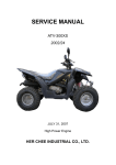
This Service Manual describes the
technical features and servicing
procedures for the KYMCO MXU 50
REVERSE/MXU 50/MX’ER 50.
TABLE OF CONTENTS
Section 1 contains the precautions for
all operations stated in this manual.
Read them carefully before starting any
operation.
ENGINE
Section 2 is the removal/installation
procedures for the frame covers which
are subject to higher removal/installation
frequency during maintenance and
servicing operations.
Section 3 describes the inspection/
adjustment procedures, safety rules and
service information for each part,
starting from periodic maintenance.
ELECTRICAL
EQUIPMENT
Most sections start with an assembly or
system illustration and troubleshooting
for the section. The subsequent pages
give detailed procedures for the section.
CHASSIS
Sections 4 through 19 give instructions
for disassembly, assembly and
inspection of engine, chassis frame and
electrical equipment.
1
FRAME COVERS/EXHAUST MUFFLER
2
INSPECTION/ADJUSTMENT
3
LUBRICATION SYSTEM
4
FUEL SYSTEM
5
ENGINE REMOVAL/INSTALLATION
6
CYLINDER HEAD/CYLINDER/PISTON 7
A.C. GENERATOR
8
GENERAL INFORMATION
KICK STARTER/DRIVE
PULLEY/CLUTCH/DRIVEN PULLEY
FINAL REDUCTION
(MXU 50/MX’ER 50)
FINAL REDUCTION/TRANSMISSION
SYSTEM (MXU 50 REVERSE)
CRANKCASE/CRANKSHAFT
FRONT WHEEL/FRONT BRAKE/
FRONT SUSPENSION/STEERING
SYSTEM
KWANG YANG MOTOR CO., LTD.
OVERSEAS SALES DEPARTMENT
OVERSEAS SERVICE SECTION
10
11
12
13
REAR WHEEL /SWING
ARM/HYDRAULIC BRAKE
14
BATTERY/CHARGING SYSTEM/A.C.
GENERATOR
15
IGNITION SYSTEM
STARTING SYSTEM
LIGHTS/SWITCHES
ONLY ATV ON ROAD AVAILABLE
The information and contents included in
this manual may be different from the
ATV in case specifications are changed.
KYMCO reserves the right to make
changes at any time without notice and
without incurring any obligation.
9
16
17
18
19
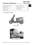
1. GENERAL INFORMATION
ATV 50
1
1
__________________________________________________________________________________
__________________________________________________________________________________
__________________________________________________________________________________
__________________________________________________________________________________
__________________________________________________________________________________
GENERAL INFORMATION
__________________________________________________________________________________
SERIAL NUMBER---------------------------------------------------------SPECIFICATIONS ---------------------------------------------------------SERVICE PRECAUTIONS -----------------------------------------------TORQUE VALUES --------------------------------------------------------SPECIAL TOOLS ----------------------------------------------------------LUBRICATION POINTS -------------------------------------------------CABLE & HARNESS ROUTING (MX’ER 50) -----------------------CABLE & HARNESS ROUTING (MXU 50 REVERSE/MXU 50) WIRING DIAGRAM (MX’ER 50 ON ROAD) ------------------------WIRING DIAGRAM (MX’ER 50 OFF ROAD) -----------------------WIRING DIAGRAM (MXU 50 ON ROAD) ---------------------------WIRING DIAGRAM (MXU 50 REVERSE ON ROAD) -------------TROUBLESHOOTING-----------------------------------------------------
1- 1
1- 2
1- 5
1-13
1-14
1-14
1-17
1-21
1-26
1-27
1-28
1-29
1-30
1-0
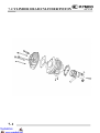
1. GENERAL INFORMATION
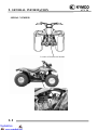
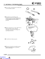
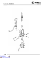
SERIAL NUMBER
Location of Frame Serial Number
Location of Engine Serial Number
1-1
ATV 50
1. GENERAL INFORMATION
ATV 50
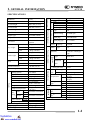
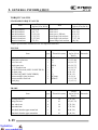
SPECIFICATIONS
Overall length
1685 mm (67.4 in)
Overall width
980 mm (39.2 in)
Overall height
1030 mm (41.2 in)
Wheel base
1120 mm (44.8 in)
Engine type
Air cooled 2-stroke
Displacement
49.4 cm3 (2.964 cu-in)
Fuel Used
92# nonleaded
gasoline
Dry weight
Type
CDI
Ignition timing
22°/2000 rpm
Spark plug
NGK-BR8HAS
Spark plug gap
0.6~0.7mm
67 kg (147.4 lbs)
Battery Capacity
12V4AH
Rear wheel
73 kg (160.6 lbs)
Clutch
CVT
Total
140 kg (308 lbs)
Front wheel
73 kg (160.6 lbs)
Rear wheel
77 kg (169.4 lbs)
Total
150 kg (330 lbs)
Front wheel
20*7-8
Rear wheel
22*10-8
Ground clearance
130 mm (5.2 in)
Automatic centrifugal
Type
Type
Chain drive
Reduction
1st -
ratio
2nd -
Final gear ratio
Min. turning radius
Moving Device
Engine
Front
Axle
23.678
-
-
0.35 kgf/cm2 (35 kPa,
4.97 psi)
Rear 0.35 kgf/cm2 (35 kPa,
4.97 psi)
Left
44°
Right 44°
Rear Disk brake
Front Drum brake
Front Swing
Rear Swing arm
Front Swing
Rear Swing arm
SP pipe
Caster angle
Trail length
Front
Tire pressure
Turning
angle
Brake system
type
Suspension
type
Shock
b b
type
Frame type
Damping
Device
2500 mm (100 in)
Starting motor &
Starting system
kick starter
Type
Air cooled 2-stroke
Cylinder arrangement
Single cylinder
Combustion chamber type Semi-sphere
Valve arrangement
Reed valve & piston
39 x 41.4 mm
Bore x stroke
(1.56 x 1.656 in)
Compression ratio
7.2:1
12 kgf/cm2 (1200 kPa,
Compression pressure
170.4 psi)
Open
Intake
Automatic controlled
Close
Port
timing
Open
Exhaust
Automatic controlled
Close
Intake -
Valve clearance
Exhaust -
Idle speed (rpm)
1800
Lubrication type
Separate type
Oil pump type
Plunger type
Oil filter type
Full-flow filtration
Type
Operation
Reduction
Gear
Tires
Sponge
8.1 liters
PB
80
φ14 mm (φ0.56 in)
Valve piston
Front wheel
Power Drive System
Curb weight
Ignition System
MX’ER 50
Air cleaner type
Fuel capacity
Type
Main jet No.
Venturi dia
Throttle type
Carburetor
Name
Electrical Equipment
LA10
Fuel System
Model No.
1-2
1. GENERAL INFORMATION
Overall length
1775 mm (71 in)
Overall width
950 mm (38 in)
Overall height
1040 mm (41.6 in)
Wheel base
1120 mm (44.8 in)
Engine type
Air cooled 2-stroke
Displacement
49.4 cm3 (2.964 cu-in)
Fuel Used
92# nonleaded
gasoline
Dry weight
Rear wheel
89 kg (195.8 lbs)
Total
176 kg (387.2 lbs)
Front wheel
92 kg (202.4 lbs)
Rear wheel
94 kg (206.8 lbs)
Total
186 kg (409.2 lbs)
Front wheel
21*7-10
Rear wheel
22*10-10
Ground clearance
CDI
Ignition timing
22°/2000 rpm
Spark plug
NGK-BR8HAS
Spark plug gap
0.6~0.7mm
Battery Capacity
12V8AH
Clutch
CVT
Type
Operation
Automatic centrifugal
Type
Type
Chain drive
Reduction
1st -
ratio
2nd -
165 mm (6.6 in)
Moving Device
Engine
Front
Axle
Tire pressure
23.678
-
-
0.28 kgf/cm2 (28 kPa, 4
psi)
Rear 0.28 kgf/cm2 (28 kPa, 4
psi)
Left
40°
Right 40°
Rear Disk brake
Front Drum brake
Front Swing
Rear Swing arm
Front Swing
Rear Swing arm
SP pipe
Caster angle
Trail length
Front
Turning
angle
Brake system
type
Suspension
type
Shock
b b
type
Frame type
Damping
Device
2900 mm (116 in)
Starting motor &
Starting system
kick starter
Type
Air cooled 2-stroke
Cylinder arrangement
Single cylinder
Combustion chamber type Semi-sphere
Valve arrangement
Reed valve & piston
39 x 41.4 mm
Bore x stroke
(1.56 x 1.656 in)
Compression ratio
7.2:1
12 kgf/cm2 (1200 kPa,
Compression pressure
170.4 psi)
Open
Intake
Automatic controlled
Close
Port
timing
Open
Exhaust
Automatic controlled
Close
Intake -
Valve clearance
Exhaust -
Idle speed (rpm)
1800
Lubrication type
Separate type
Oil pump type
Plunger type
Oil filter type
Full-flow filtration
Final gear ratio
Min. turning radius
1-3
Sponge
8.1 liters
PB
80
φ14 mm (φ0.56 in)
Valve piston
Type
Reduction
Gear
Tires
87 kg (191.4 lbs)
Power Drive System
Curb weight
Front wheel
Ignition System
MXU 50
Air cleaner type
Fuel capacity
Type
Main jet No.
Venturi dia
Throttle type
Carburetor
Name
Electrical Equipment
LB10
Fuel System
Model No.
ATV 50
1. GENERAL INFORMATION
Overall length
1786 mm (71 in)
Overall width
958 mm (38 in)
Overall height
1010 mm (40 in)
Wheel base
1105 mm (44 in)
Engine type
Air cooled 2-stroke
Displacement
49.4 cm3 (2.964 cu-in)
Fuel Used
92# nonleaded
gasoline
Dry weight
Tires
78 kg (171.6 lbs)
Rear wheel
80 kg (176 lbs)
Total
158 kg (347.6 lbs)
Front wheel
83 kg (182.6 lbs)
Rear wheel
84 kg (184.8 lbs)
Total
167 kg (36734 lbs)
Front wheel
21*7-10
Rear wheel
22*10-10
Ground clearance
Power Drive System
Curb weight
Front wheel
162 mm (6.6 in)
Min. turning radius
Moving Device
Engine
Sponge
8.1 liters
PB
80
φ14 mm (φ0.56 in)
Valve piston
Type
CDI
Ignition timing
13.5°/1500 rpm
Spark plug
NGK-BR8HAS
Spark plug gap
0.6~0.7mm
Battery Capacity
12V8AH
Clutch
CVT
Type
Automatic centrifugal
Type
Operation
Primary reduction
system
Secondary reduction
system
Primary reduction ratio
Secondary reduction
ratio
Reverse ratio
Front Caster angle
Axle Trail length
Front
Tire pressure
Turning
angle
Brake system
type
Suspension
type
Shock
b b
type
Frame type
Damping
Device
2900 mm (116 in)
Starting motor &
Starting system
kick starter
Type
Air cooled 2-stroke
Cylinder arrangement
Single cylinder
Combustion chamber type Semi-sphere
Valve arrangement
Reed valve & piston
39 x 41.4 mm
Bore x stroke
(1.56 x 1.656 in)
Compression ratio
7.2:1
12 kgf/cm2 (1200 kPa,
Compression pressure
170.4 psi)
Open
Intake
Automatic controlled
Close
Port
timing
Open
Exhaust
Automatic controlled
Close
Intake -
Valve clearance
Exhaust -
Idle speed (rpm)
1800
Lubrication type
Separate type
Oil pump type
Plunger type
Oil filter type
Full-flow filtration
Ignition System
MXU 50 REVERSE
Air cleaner type
Fuel capacity
Type
Main jet No.
Venturi dia
Throttle type
Carburetor
Name
Electrical Equipment
LB10
Fuel System
Model No.
ATV 50
Helical gear/spur gear
Chain drive
1.2 – 3.5
20.12
46.11
-
-
0.28 kgf/cm2 (28 kPa, 4
psi)
Rear 0.28 kgf/cm2 (28 kPa, 4
psi)
Left
40°
Right 40°
Rear Disk brake
Front Drum brake
Front Swing
Rear Swing arm
Front Swing
Rear Swing arm
SP pipe
1-4
1. GENERAL INFORMATION
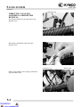
SERVICE PRECAUTIONS
Make sure to install new gaskets, O-rings,
circlips, cotter pins, etc. when
reassembling.
When tightening bolts or nuts, begin with
larger-diameter to smaller ones at several
times, and tighten to the specified torque
diagonally.
Use genuine parts and lubricants.
When servicing the motorcycle, be sure to
use special tools for removal and
installation.
After disassembly, clean removed parts.
Lubricate sliding surfaces with engine oil
before reassembly.
1-5
ATV 50
1. GENERAL INFORMATION
ATV 50
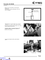
Apply or add designated greases and
lubricants to the specified lubrication
points.
After reassembly, check all parts for proper
tightening and operation.
When two persons work together, pay
attention to the mutual working safety.
Disconnect the battery negative (-) terminal
before operation.
When using a spanner or other tools, make
sure not to damage the motorcycle surface.
After operation, check all connecting
points, fasteners, and lines for proper
connection and installation.
When connecting the battery, the positive
(+) terminal must be connected first.
After connection, apply grease to the
battery terminals.
Terminal caps shall be installed securely.
1-6
1. GENERAL INFORMATION
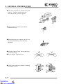
If the fuse is burned out, find the cause and
repair it. Replace it with a new one
according to the specified capacity.
After operation, terminal caps shall be
installed securely.
When taking out the connector, the lock on
the connector shall be released before
operation.
Hold the connector body when connecting
or disconnecting it.
Do not pull the connector wire.
Check if any connector terminal is bending,
protruding or loose.
1-7
ATV 50
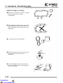
Confirm
Capacity
1. GENERAL INFORMATION
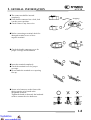
The connector shall be inserted
completely.
If the double connector has a lock, lock
it at the correct position.
Check if there is any loose wire.
ATV 50
Snapping!
Before connecting a terminal, check for
damaged terminal cover or loose
negative terminal.
Check the double connector cover for
proper coverage and installation.
Insert the terminal completely.
Check the terminal cover for proper
coverage.
Do not make the terminal cover opening
face up.
Secure wire harnesses to the frame with
their respective wire bands at the
designated locations.
Tighten the bands so that only the insulated
surfaces contact the wire harnesses.
1-8
1. GENERAL INFORMATION
ATV 50
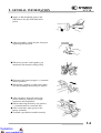
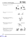
After clamping, check each wire to make
sure it is secure.
Do not squeeze wires against the weld or
its clamp.
After clamping, check each harness to
make sure that it is not interfering with any
moving or sliding parts.
When fixing the wire harnesses, do not
make it contact the parts which will
generate high heat.
Route wire harnesses to avoid sharp edges
or corners. Avoid the projected ends of
bolts and screws.
Route wire harnesses passing through the
side of bolts and screws. Avoid the
projected ends of bolts and screws.
1-9
No Contact !
1. GENERAL INFORMATION
ATV 50
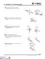
Route harnesses so they are neither
pulled tight nor have excessive slack.
Do not pull too
tight!
Protect wires and harnesses with electrical
tape or tube if they contact a sharp edge or
corner.
When rubber protecting cover is used to
protect the wire harnesses, it shall be
installed securely.
Do not break the sheath of wire.
If a wire or harness is with a broken sheath,
repair by wrapping it with protective tape
or replace it.
When installing other parts, do not press or
squeeze the wires.
Do not press or
squeeze the wire.
1-10
1. GENERAL INFORMATION
ATV 50
After routing, check that the wire harnesses
are not twisted or kinked.
Wire harnesses routed along with
handlebar should not be pulled tight, have
excessive slack or interfere with adjacent
or surrounding parts in all steering
positions.
When a testing device is used, make sure to
understand the operating methods
thoroughly and operate according to the
operating instructions.
Do you understand the
instrument? Is the
instrument set
correctly?
Be careful not to drop any parts.
When rust is found on a terminal, remove
the rust with sand paper or equivalent
before connecting.
1-11
Remove Rust !
1. GENERAL INFORMATION
ATV 50
Symbols:
The following symbols represent the
servicing methods and cautions included in
this service manual.
Engine Oil
Grease
: Apply engine oil to the
specified points. (Use
designated engine oil for
lubrication.)
: Apply grease for lubrication.
Special
*
: Caution
: Warning
1-12
1. GENERAL INFORMATION
ATV 50
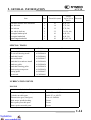
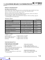
TORQUE VALUES
STANDARD TORQUE VALUES
Torque
kgf-m (N-m, lbf-ft)
Item
5mm bolt and nut
6mm bolt and nut
8mm bolt and nut
10mm bolt and nut
12mm bolt and nut
14mm bolt and nut
Torque
kgf-m (N-m, lbf-ft)
Item
0.5 (5, 3.6)
1 (10, 7.2)
2.2 (22, 16)
3.5 (35, 25)
5.5 (55, 40)
7 (70, 50)
4mm screw
5mm screw
6mm screw, SH bolt
6mm flange bolt and nut
8mm flange bolt and nut
10mm flange bolt and nut
0.3 (3, 2.2)
0.4 (4, 2.9)
0.9 (9, 6.5)
1.2 (12, 9)
2.7 (27, 20)
4 (40, 29)
Torque specifications listed below are for important fasteners.
ENGINE
Item
Cylinder head bolt
Clutch drive plate nut
Drive face nut
Clutch outer nut
A.C.G flywheel nut
Oil check/filler bolt (MXU 50/MX’ER 50)
Oil drain plug
Oil filler bolt (MXU 50 REVERSE)
Exhaust muffler joint lock nut
Exhaust muffler lock bolt
Spark plug
Torque
kgf-m (N-m,
Q‘ty Thread dia.(mm)
lbf-ft)
4 BF7X115
1.6 (16, 11.5)
1 39
5.5 (55, 40)
1 12
3.8 (38, 27)
1 NH10
3.8 (38, 27)
1 10
3.8 (38, 27)
1 8
1.2 (12, 9)
1 8
2 (20, 15)
1 12
2 (20, 15)
2 NC6mm
1.2 (12, 9)
2 BF8X35
3.3 (33, 24)
1.5 (15, 11)
Remarks
FRAME
Item
Steering stem nut
Swing arm nut
Rear wheel nut
Front wheel nut
Rear shock absorber upper mount bolt
Front shock absorber upper mount bolt
Q‘ty
Thread dia.(mm)
1
4
4
4
1
2
14
10
14
14
10
10
Torque
kgf-m (N-m,
lbf-ft)
Remarks
7 (70, 50)
4.5 (45, 32)
7 (70, 50)
7 (70, 50)
4 (40, 29)
4 (40, 29)
(Cont’d)
1-13
1. GENERAL INFORMATION
Item
Front shock absorber lower mount bolt
Rear fork axle
Rear hub nut
Rear wheel shaft nut
Rear engine bracket up bolt
Rear engine bracket bolt
Engine hanger bracket bolt
ATV 50
Q‘ty
Thread dia.(mm)
2
1
4
2
1
2
1
10
14
12
32
10
10
10
Torque
kgf-m (N-m,
lbf-ft)
Remarks
4 (40, 29)
7 (70, 50)
7 (70, 50)
12 (120, 86)
4 (40, 29)
4 (40, 29)
4.5 (45, 32)
SPECIAL TOOLS
Tool Name
Flywheel puller
Oil seal and bearing install
Crankshaft install
Universal holder
Crankshaft & crankcase install
Crankcase puller
Crankshaft Bearing puller
Clutch spring compressor
Bearing puller
Nut wrench
Tool No.
A120E00001
A120E00014
A120E00016
A120E00017
A120E00024
A120E00026
A120E00030
A120E00034
A120E00037
A120F00010
Memo
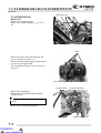
LUBRICATION POINTS
ENGINE
Lubrication Points
Crankcase sliding & movable parts
Cylinder movable parts
Transmission gear (final gear)
Kick starter spindle bushing
Drive pulley movable parts
Starter pinion movable parts
Lubricant
JASO-FC or API-TC
JASO-FC or API-TC
Gear oil: SAE90#
Grease
Grease
Grease
1-14
1. GENERAL INFORMATION
ATV 50
FRAME
The following is the lubrication points for the frame.
Use general purpose grease for parts not listed.
Apply clean engine oil or grease to cables and movable parts not specified.
abnormal noise and rise the durability of the motorcycle.
This will avoid
Rear Brake Cable
Front Brake Cable
Throttle Cable
Front Arm Bush
Steering Column Upper
Front Arm Bush
Front Brake
camshaft/Oil
Seal/O-ring
Front Brake
camshaft/Oil
Seal/O-ring
Front Wheel
Oil Seal
Steering Column Lower
Steering knuckle/Thrust
Cover/Bush/Collar
1-15
Steering knuckle/Thrust
Cover/Bush/Collar
Front Wheel
Oil Seal
1. GENERAL INFORMATION
ATV 50
Swing arm Thrust
Cover
Rear Brake Cam/
Axle Hub Collar/Oil
Seal/Bearing
Sprocket hub/Rear
Axle Hub Collar/Oil
Seal/Bearing
Driven Sprocket
1-16
1. GENERAL INFORMATION
ATV 50
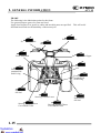
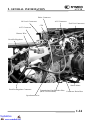
CABLE & HARNESS ROUTING (MX’ER 50)
Rear Brake Cable
Throttle Cable
Front Brake Cable
Handlebar Switch Lead
A.C.G Wire
Starter Motor Wire
Auto Bystarter
Wi
Left Front Brake Cable
Right Front Brake Cable
1-17
1. GENERAL INFORMATION
ATV 50
Fuel Filter
Fuel Tube
Throttle Cable
Ignition Coil Wire
Oil Meter Wire
Left Front Brake Cable
Right Front Brake Cable
Rear Brake Cable
1-18
1. GENERAL INFORMATION
ATV 50
Ignition Coil
Wire Harness
Rectifier/Regulator
Resistor
Oil Tube
Right Front Brake Cable
1-19
1. GENERAL INFORMATION
ATV 50
Main Switch
Rear Brake Cable
Breather Hose
Oil Meter Wire
Battery
Negative Cable
Positive Cable
Starter Relay
CDI Unit
Fuse
1-20
1. GENERAL INFORMATION
ATV 50
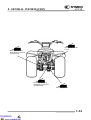
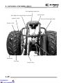
CABLE & HARNESS ROUTING (MXU 50 REVERSE/MXU 50)
Fuel Tank Breather Hose
Throttle Cable
Rear Brake Light Switch Wire
Front Brake Cable
Rear Brake Fluid Hose
Front Brake Light
Switch Wire
Instrument Connector
Right Headlight/
Turn Signal Light Connectors
Handlebar Switch Connectors
Left Headlight/
Turn Signal Light Connector
Resistor
Ignition Switch
Connectors
Horn
Left Front Brake Cable
Right Front Brake Cable
1-21
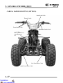
1. GENERAL INFORMATION
ATV 50
Inlet Hose
Ignition Coil
Oil Inlet Hose
Fuel Valve
Auto Choke Connector
Air Cleaner
Throttle Cables
Spark Plug Cap
Rear Brake Hose
Neutral Switch Wire
(MXU 50 REVERSE)
Starter Motor Connector
1-22
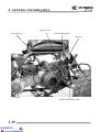
1. GENERAL INFORMATION
Fuel Unit Connectors
ATV 50
Ignition Coil
Ignition Coil Wire
Hazard Unit
Harness Wire
Headlight Control Unit
Throttle Cable
Oil Outlet Hose
Starter Motor Cable
Fuel Drain Hose
ACG Wire
Ignition Coil Cable
Transmission Case Breather
Hose (MXU 50 REVERSE)
Neutral Switch Wire (MXU 50 REVERSE)
1-23
1. GENERAL INFORMATION
ATV 50
Pulser Connector
Oil Level Connectors
ACG Connector
Fuel Unit Connectors
CDI
ACG Connector
Harness Wire
Rectifier/Regulator
Starter Motor
Rectifier/Regulator Connector
Transmission Case Breather Hose
Carburetor Drain Hose
(MXU 50 REVERSE)
Speedometer wire
1-24
1. GENERAL INFORMATION
ATV 50
Tail Light/Brake light Wire
Speed Sensor
Rear Right Turn Signal Light Connectors
Negative Cable
Rear Left Turn Signal Light
Positive Cable
Speedometer Wire
Start Relay
Fuse Box
Harness Wire
1-25
Rear Brake Hose
1. GENERAL INFORMATION
ATV 50
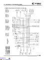
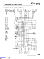
WIRING DIAGRAM (MX’ER 50) (ON ROAD)
1-26
1. GENERAL INFORMATION
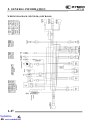
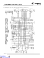
WIRING DIAGRAM (MX’ER 50) (OFF ROAD)
1-27
ATV 50
1. GENERAL INFORMATION
ATV 50
WIRING DIAGRAM (MXU 50) (ON ROAD)
1-28
1. GENERAL INFORMATION
WIRING DIAGRAM (MXU 50 REVERSE) (ON ROAD)
1-29
ATV 50
1. GENERAL INFORMATION
ATV 50
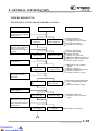
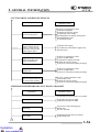
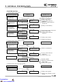
TROUBLESHOOTING
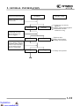
ENGINE WILL NOT START OR IS HARD TO START
Inspection/Adjustment
Probable Cause
Symptom
Check if fuel reaches
carburetor by loosening
drain screw.
Fuel reaches
carburetor
Fuel does not
reach carburetor
Remove spark plug and
install it into spark plug
cap to test spark by
connecting it to engine
ground.
Spark jumps
Weak or no spark
Test cylinder
compression.
Normal
compression
Low or no
compression
Start engine by following normal starting
procedure.
Engine does not
fire
Engine fires but
does not start
Dry spark plug
Wet spark plug
Not clogged
Clogged
c Empty fuel tank
d Clogged float valve
e Clogged charcoal canister
f Clogged fuel filter
g Faulty auto fuel valve
c Faulty spark plug
d Fouled spark plug
e Faulty CDI unit
f Faulty A.C. generator
g Broken or shorted ignition coil
h Broken or shorted exciter coil
iFaulty ignition switch
c Burned or worn cylinder
piston
d Faulty reed valve
e Blown cylinder head gasket
f Leaking crankcase
g Faulty crankcase oil seal
c Incorrectly adjusted idle speed
d Air leaking through intake
pipe
e Incorrect ignition timing
Remove spark plug and
inspect again.
Wait for 30 minutes and
then remove the carburetor auto choke circuit
hose and blow the hose
with mouth.
c Flooded carburetor
d Throttle valve excessively
open
c Faulty auto bystarter
1-30
1. GENERAL INFORMATION
ATV 50
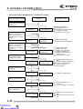
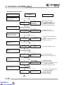
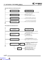
ENGINE STOPS IMMEDIATELY AFTER IT STARTS
Inspection/Adjustment
Symptom
Probable Cause
Check if fuel reaches
carburetor by loosening
drain screw.
Fuel reaches
carburetor
Fuel does not
reach carburetor
c Empty fuel tank
d Clogged float valve
e Clogged charcoal canister
f Clogged fuel filter
g Faulty auto fuel valve
Plug fouled or
discolored
c Fouled spark plug
d Incorrect heat range plug
Remove spark plug and
install it into spark plug
cap to test spark by
connecting it to engine
ground.
Plug not fouled or
discolored
Remove spark plug and
install it into spark plug
cap to test spark by
connecting it to engine
ground.
Good spark
Weak or intermittent spark
Test cylinder
compression (using a
compression gauge).
c Fouled spark plug
d Faulty CDI unit
e Faulty A.C. generator
f Faulty ignition coil
g Broken or shorted high
tension wire
h Faulty ignition switch
c Worn cylinder and piston
rings
d Blown cylinder head gasket
e Flaws in cylinder head
f Faulty reed valve
g Seized piston
Normal
compression
Abnormal
compression
Not Clogged
Clogged
Correct timing
Incorrect timing
c Faulty CDI unit or A.C.
generator
d A.C.G. flywheel not aligned
Correctly adjusted
Incorrectly adjusted
c Mixture too rich (turn screw
out)
d Mixture too lean (turn screw
in)
Check carburetor for
clogging.
c Clogged carburetor jets
Check ignition timing.
Check carburetor air
screw adjustment.
1-31
1. GENERAL INFORMATION
Inspection/Adjustment
ATV 50
Probable Cause
Symptom
Check carburetor gasket
for air leaks.
No air leak
Air leaks
c Carburetor not securely
tightened
d Faulty intake manifold gasket
e Deformed or broken
carburetor O-ring
Not clogged
Clogged
c Broken cable
d Dirty auto bystarter
e Faulty auto bystarter
Clogged
Not Clogged
c Faulty auto bystarter
Remove auto bystarter
connecting wire and
check if bypass fuel
line is clogged.
Connect auto bystarter
wire to battery. Wait for
5 minutes, then connect
a hose to fuel enriching
circuit and then blow
the hose with mouth.
1-32
1. GENERAL INFORMATION
ATV 50
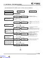
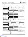
ENGINE LACKS POWER
Inspection/Adjustment
Symptom
Probable Cause
Start engine and
accelerate lightly for
observation.
Engine speed
increases
Engine speed does
not increase
sufficiently
Correct timing
Incorrect timing
Normal
compression
Abnormal
compression
Not Clogged
Clogged
c Clogged air cleaner
d Clogged fuel filter
e Clogged exhaust muffler
f Faulty auto bystarter
g Faulty charcoal canister
Check ignition timing
(using a timing light).
c Faulty CDI unit
d Faulty A.C. generator
Test cylinder
compression (using a
compression gauge)
c Worn cylinder and piston
rings
d Blown cylinder head gasket
e Faulty reed valve
Check carburetor for
clogging
c Clogged carburetor jets
Remove spark plug and
inspect
Plug not fouled or
discolored
Plug fouled or
discolored
c Fouled spark plug
d Incorrect heat range plug
Engine overheats
c Mixture too lean
d Poor quality fuel
e Excessive carbon build-up in
combustion chamber
f Ignition timing too early
Engine knocks
c Excessive carbon build-up in
combustion chamber
d Poor quality fuel
e Clutch slipping
f Mixture too lean
Check if engine
overheats
Engine does not
overheats
Rapidly accelerate or
run at high speed
Engine does not
knock
1-33
1. GENERAL INFORMATION
ATV 50
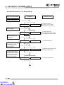
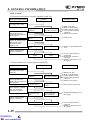
POOR PERFORMANCE (ESPECIALLY AT IDLE AND LOW SPEEDS)
Inspection/Adjustment
Symptom
Probable Cause
Check ignition timing.
Correct timing
Incorrect timing
Correctly adjusted
Incorrectly adjusted
c Faulty CDI unit
d Faulty A.C. generator
Check carburetor air
screw adjustment.
c Mixture too rich (turn screw
out)
d Mixture too lean (turn screw
in)
Check carburetor gasket
for air leaks.
Air leaks
c Carburetor not securely
tightened
d Faulty intake manifold gasket
e Deformed carburetor O-ring
Good spark
Weak or intermittent spark
c Faulty or fouled spark plug
d Faulty CDI unit
e Faulty A.C. generator
f Faulty ignition coil
g Broken or shorted high
tension wire
h Faulty ignition switch
Not clogged
Clogged
Clogged
Not clogged
No air leak
Remove spark plug and
install it into spark plug
cap to test spark by
connecting it to engine
ground.
Remove auto bystarter
connecting wire and
check if bypass fuel
line is clogged.
Connect auto bystarter
wire to battery. Wait for
5 minutes, then connect
a hose to fuel enriching
circuit and then blow
the hose with mouth.
c Broken auto bystarter wire
d Faulty auto bystarter
1-34
1. GENERAL INFORMATION
ATV 50
POOR PERFORMANCE (AT HIGH SPEED)
Inspection/Adjustment
Symptom
Probable Cause
Check ignition timing.
c Faulty CDI unit
d Loose A.C.G. stator
e Faulty A.C. generator
Correct timing
Incorrect timing
Fuel flows freely
Fuel flow restricted
Not clogged
Clogged
c Clean and unclog
Not clogged
Clogged
c Broken auto bystarter wire
d Faulty auto bystarter
Clogged
Not clogged
Check auto fuel valve
for fuel supply.
c Empty fuel tank
d Clogged fuel tube or filter
e Clogged charcoal canister
Check carburetor jets
for clogging.
Remove auto bystarter
connecting wire and
check if bypass fuel
line is clogged.
Connect auto bystarter
wire to battery. Wait for
5 minutes, then connect
a hose to fuel enriching
circuit and then blow
the hose with mouth.
1-35
c Faulty auto bystarter
1. GENERAL INFORMATION
ATV 50
CLUTCH, DRIVE AND DRIVEN PULLEYS
Symptom
Probable Cause
Engine starts but motorcycle does not move
c Worn or slipping drive belt
d Broken ramp plate
e Broken driven face spring
f Separated clutch lining
g Damaged driven pulley shaft splines
h Damaged final gear
i Seized final gear
Motorcycle creeps or
engine starts but soon
stops or seems to rush
out (Rear wheel rotates
when engine idles)
c Broken shoe spring
d Clutch outer and clutch weight stuck
eSeized pivot
Engine lacks power at
start of a grade (poor
slope performance)
c Worn or slipping drive belt
d Worn weight rollers
e Seized drive pulley bearings
f Weak driven face spring
g Worn or seized driven pulley bearings
Engine lacks power at
high speed
c Worn or slipping drive belt
d Worn weight rollers
e Worn or seized driven pulley bearings
There is abnormal noise
or smell while running
c Oil or grease fouled drive belt
d Worn drive belt
e Weak driven face spring
f Worn or seized driven pulley bearings
STEERING HANDLEBAR DOES NOT TRACK STRAIGHT
Symptom
Probable Cause
(Front and rear tire pressures are normal)
Steering is heavy
c Steering stem nut too tight
d Broken steering steel balls
Front or rear wheel is
wobbling
c Excessive wheel bearing play
d Bent rim
e Loose axle nut
Steering handlebar pulls
to one side
c Misaligned front and rear wheels
d Bent front fork
1-36
1. GENERAL INFORMATION
ATV 50
POOR SUSPENSION PERFORMANCE
Symptom
Probable Cause
(Front and rear tire pressures are normal)
Suspension is too soft
c Weak shock spring
d Excessive load
e Shock damper oil leaking
Suspension is too hard
c Bent fork tube or shock rod
d Fork slider and tube binding
Suspension is noisy
c Fork tube and spring binding
d Fork slider and tube binding
POOR BRAKE PERFORMANCE
Symptom
Probable Cause
(Adjust brake according to standards)
Index mark on brake
panel aligns with wear
indicator arrow
c Worn brake linings
d Worn brake cam contacting area on
brake shoes
e Worn brake cam
f Worn brake drum
Brake squeaks
c Worn brake linings
d Foreign matter on brake linings
e Rough brake drum contacting area
Brake performance is
poor
c Sluggish or elongated brake cables
d Brake shoes improperly contact
brake drum
e Water and mud in brake system
f Oil or grease on brake linings
Expanding
Brake
Hydraulic
Brake
1-37
c Faulty brake master cylinder
d Faulty brake caliper
e Oil or grease on brake disk
f Deformed brake disk
g Leaking brake fluid tube
1. GENERAL INFORMATION
ATV 50
OIL METER
1. Motor oil indicator light does not come on when there is no motor oil (Ignition switch ON)
Inspection/Adjustment
Symptom
Probable Cause
Check battery circuit by
operating turn signals.
Signals operate
properly
Signals dim, remain
on or don‘t operate
c Burned out fuse
d Weak or dead battery
e Faulty ignition switch
f Loose or disconnected
connector
g Broken wire harness
Bulb lights
Bulb does not light
cBurned out bulb
Good
Faulty
c Loose wire connector
d Broken wire harness
e Incorrectly connected wire
Good
Faulty
c Faulty float
d Broken or shorted wire in
meter
Connect indicator light
bulb to battery for bulb
inspection.
Check connectors for
proper operation.
Remove oil meter and
check operation of
indicator light by
moving float
Float up = Light off
Float down = Light on
2. Motor oil is sufficient but the indicator light remains on (Ignition switch ON)
Inspection/Adjustment
Probable Cause
Symptom
Check connectors for
proper connection.
Good
Faulty
Good
Faulty
Remove oil meter and
check operation of
indicator light by
moving float
Float up = Light off
Float down = Light on
c Loose or disconnected
connector
d Broken wire harness
e Incorrectly connected wire
c Faulty float
d Broken or shorted wire in
meter
c Damaged oil tank
d Foreign matters in oil tank
1-38
1. GENERAL INFORMATION
ATV 50
FUEL GAUGE
1. Pointer does not register correctly (Ignition switch ON)
Inspection/Adjustment
Probable Cause
Symptom
Check battery circuit by
operating turn signals.
Remove fuel unit and
check operation of
pointer by moving float
up and down.
Check operation of
pointer by opening and
shorting fuel unit
terminal on wire
harness side.
Signals operate
properly
Signals dim, remain
on or don‘t operate
Pointer does not
move
Pointer does not
move
c Burned out fuse
d Weak or dead battery
e Faulty ignition switch
f Loose or disconnected
connector
g Broken wire harness
Pointer moves
c Faulty float
Pointer moves
c Broken or shorted fuel unit
wire
Check connectors for
proper connection.
c Loose or disconnected
Faulty
Good
connector
d Incorrectly connected
connector
c Broken or shorted wire in
fuel gauge
2. Pointer fluctuates or swings (Ignition switch ON)
Probable Cause
Symptom
Inspection/Adjustment
Check battery circuit by
operating turn signals
and horn.
Remove fuel unit and
check operation of
pointer by moving float
up and down.
Signals operate
properly
Pointer moves
Move float up and
down rapidly (1 round
/sec.) to check the
operation of pointer.
Pointer moves in
accordance with
float
Signals dim, remain
on or don‘t operate
Pointer does not
move
Pointer does not
move in accordance with float
c Burned out fuse
d Weak or dead battery
e Faulty ignition switch
f Loose or disconnected
connector
g Broken wire harness
c Poor contact in fuel unit
c Insufficient damping oil in
fuel gauge
Check connectors for
proper connection.
Good
1-39
Faulty
c Loose or disconnected
connector
c Broken or shorted wire in
fuel gauge
1. GENERAL INFORMATION
ATV 50
STARTER MOTOR
1. Starter motor won‘t turn
Symptom
Inspection/Adjustment
Probable Cause
Check operation of
stop switch by
applying brake.
Stoplight does not
come on
c Burned out fuse
d Weak or dead battery
e Faulty stop switch
f Loose or disconnected
connector
g Broken or shorted ignition
switch wire
Signals operate
properly
Signals dim, remain
on or don‘t operate
c Faulty or weak battery
Relay operates
properly
Relay does not
operate
Starter motor turns
Starter does not turn
Stoplight comes on
Check battery circuit
by operating turn
signals.
Check operation of
starter relay by
depressing starter
button.
Connect starter
motor directly to
battery.
c Poor starter button connection
d Faulty starter relay
e Loose or disconnected
connector
c Faulty starter motor
c Faulty wire harness
2. Starter motor turns slowly or idles
Symptom
Inspection/Adjustment
Probable Cause
Check battery circuit
by operating turn
signals.
Signals operate
properly
Signals dim, remain
on or don‘t operate
c Weak or dead battery
Starter motor
turns slowly
Starter motor
turns normally
c Loose or disconnected
connector
d Faulty starter relay
Connect starter
motor directly to
battery.
Rotate crankshaft.
Hard to turn
Turns easily
c Seized cylinder
c Broken or shorted starter
motor cable
d Faulty starter pinion
3. Starter motor does not stop turning
Symptom
Inspection/Adjustment
Probable Cause
Turn ignition switch
OFF.
Not stopped
Stopped
c Faulty starter pinion
c Starter relay shorted or stuck
closed
1-40
2. FRAME COVERS/EXHAUST MUFFLER
ATV 50
2
__________________________________________________________________________________
2
__________________________________________________________________________________
__________________________________________________________________________________
__________________________________________________________________________________
__________________________________________________________________________________
FRAME COVERS/EXHAUST MUFFLER
__________________________________________________________________________________
SERVICE INFORMATION-----------------------------------------------TROUBLESHOOTING----------------------------------------------------FRAME COVERS (MX’ER 50) ------------------------------------------HEADLIGHT REMOVAL (MX’ER 50) --------------------------------FASTENER REMOVAL -------------------------------------------------FRAME COVERS (MXU 50 REVERSE/MXU 50) -------------------EXHAUST MUFFLER REMOVAL (MX’ER 50)---------------------EXHAUST MUFFLER REMOVAL
(MXU 50 REVERSE/MXU 50) -------------------------------------------
2- 1
2- 1
2- 3
2- 5
2- 7
2- 8
2- 15
2- 16
2-0
2. FRAME COVERS/EXHAUST MUFFLER
ATV 50
SERVICE INFORMATION
GENERAL INSTRUCTIONS
• When removing frame covers, use special care not to pull them by force because the cover joint
claws may be damaged.
• Make sure to route cables and harnesses according to the Cable & Harness Routing.
TORQUE VALUES
Exhaust muffler lock bolt
3.3 kgf-m (33 N-m, 24 lbf-ft)
Exhaust muffler joint lock nut 1.2 kgf-m (12 N-m, 9 lbf-ft)
TROUBLESHOOTING
Noisy exhaust muffler
• Damaged exhaust muffler
• Exhaust muffler joint air leaks
Lack of power
• Caved exhaust muffler
• Exhaust muffler air leaks
• Clogged exhaust muffler
2-1
2. FRAME COVERS/EXHAUST MUFFLER
ATV 50
MX’ER 50
2-2
2. FRAME COVERS/EXHAUST MUFFLER
FRAME COVERS (MX’ER 50)
Lever
ATV 50
Seat
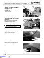
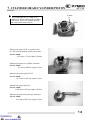
SEAT REMOVAL
Pull the lever backward, then pull up the
seat at the rear.
Remove the seat.
Screws
LEFT AND RIGHT REAR FENDER
REMOVAL
Remove seven screws and two bolts
attaching the left rear fender.
Bolt
Remove seven screws and two bolts
attaching the right rear fender.
* During removal, do not pull the joint
claws forcedly to avoid damage.
Frame Right Cover
Bolt
Bolt
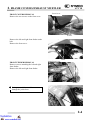
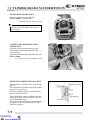
Remove the left rear fender under bolt.
Remove the left rear fender.
Remove the two bolts under right rear
fender.
Remove the right rear fender.
Bolt
2-3
2. FRAME COVERS/EXHAUST MUFFLER
FRONT COVERS REMOVAL
Remove the two screws on the front cover.
ATV 50
Front Cover
Screws
Remove the left and right front fender under
bolt.
Remove the front cover.
Bolts
FRONT FENDER REMOVAL
Remove screws attaching the left and right
front fender.
Remove the left and right front fender.
Right Front Cover
Screws
* During removal, be careful not to
damage the joint claws.
Left Front Cover
Screws
2-4
2. FRAME COVERS/EXHAUST MUFFLER
ATV 50
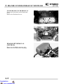
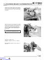
FLOOR BOARD COVER REMOVAL
Remove the four bolts on the floorboard
cover.
Remove the floorboard cover.
Bolts
Floor Board
HEADLIGHT REMOVAL
(MX’ER 50)
Remove the headlight connector wire.
Remove the two bolts on the headlight.
Bolts
2-5
2. FRAME COVERS/EXHAUST MUFFLER
ATV 50
MXU 50 REVERSE/MXU 50
2-6
2. FRAME COVERS/EXHAUST MUFFLER
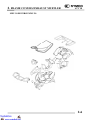
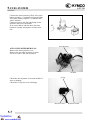
FASTENER REMOVAL AND
REINSTALLATION
REMOVAL
Depress the head of fastener center piece {.
Pull out the fastener.
INSTALLATION
Let the center piece stick out toward the
head so that the pawls | close.
Insert the fastener into the installation hole.
* To prevent the pawl | from damage,
insert the fastener all the way into the
installation hole
Push in the head of center piece until it
becomes flush with the fastener outside
face.
2-7
ATV 50
2. FRAME COVERS/EXHAUST MUFFLER
ATV 50
FRAME COVERS (MXU 50
REVERSE/MXU 50)
SEAT
REMOVAL
Pull the lever (1) backward, then pull up the
seat at the rear.
Remove the seat.
INSTALLATION
To install the seat, align the tabs on the seat
with the grommets on the frame and press
the seat down until it locks.
FRONT CARGO RACK
REMOVAL/INSTALLATION
Remove the two mounting bolts.
Mounting Bolts
2-8
2. FRAME COVERS/EXHAUST MUFFLER
ATV 50
Remove the two mounting bolts from the
front cargo rack right/left side under the
front fender, remove the front cargo rack.
Installation is in the reverse order of
removal.
Mounting Bolts
FRONT CARRIER
REMOVAL/INSTALLATION
Right/Left Signal Light Connectors
Remove front cargo rack (see page 2-8).
Disconnect the right and left signal light
connectors. (ON ROAD)
Remove the bolts from the right/left
headlight case.
Bolts
Remove the four mounting bolts from the
front carrier right/left side, then remove the
front carrier.
Installation is in the reverse order of
removal.
Mounting Bolts
2-9
2. FRAME COVERS/EXHAUST MUFFLER
ATV 50
Bolts
REAR CARGO RACK
REMOVAL/INSTALLATION
Remove the two bolts under the rear fender.
Mounting Bolts
Remove the two mounting bolts and two
mounting nuts from the rear cargo rack
right/left side under the rear fender.
Installation is in the reverse order of
removal.
Mounting Nuts
Fasteners
Fasteners
RIGHT/LEFT FOOTBOARD
REMOVAL/INSTALLATION
Remove 9 fasteners, 4 mounting bolts and
the right footboard.
Mounting Bolts
2-10
2. FRAME COVERS/EXHAUST MUFFLER
Remove 9 fasteners, 4 mounting bolts and
the left footboard.
ATV 50
Fasteners
Fasteners
* During removal, do not pull the joint
claws forcedly to avoid damage.
Installation is in the reverse order of
removal.
Mounting Bolts
RIGHT/LEFT SIDE COVER
REMOVAL/INSTALLATION
Open the seat (see page 2-8).
Remove the right/left footboard (see page 210).
Bolts
Fastener
Remove the two bolts, fastener and right
side cover.
Remove the two bolts, fastener and left side
cover.
* During removal, do not pull the joint
claws forcedly to avoid damage.
Installation is in the reverse order of
removal.
2-11
Fastener
Bolts
2. FRAME COVERS/EXHAUST MUFFLER
FRONT CENTER COVER
REMOVAL/INSTALLATION
Remove the front cargo rack (see page 2-8).
ATV 50
Screws
Remove the two screws on the front cover,
two screws under the front cover and front
center cover.
* During removal, do not pull the joint
claws forcedly to avoid damage.
Installation is in the reverse order of
removal.
Screws
Screws
ignition switch connectors
HANDLEBAR COVER
REMOVAL/INSTALLATION
Remove the front center cover (see page 212).
Disconnect the fuel tank breather hose from
the handlebar cover.
Remove the two screws and raise the
handlebar cover.
Disconnect the ignition switch connectors.
Fuel Tank Breather Hose
Disconnect the instrument connector, then
remove the handlebar cover and instrument.
instrument Connectors
Push
Installation is in the reserve order of
removal.
2-12
2. FRAME COVERS/EXHAUST MUFFLER
FUEL TANK COVER
REMOVAL/INSTALLATION
ATV 50
Screws
Screws
Remove the four screws and two nuts from
the fuel tank cover.
Remove the fuel tank cap by turning it
counterclockwise and fuel tank seal, then
remove the fuel tank cover.
* Put on the fuel tank cap after removing
the cover to prevent dust, mud, etc. from
entering the fuel tank
Fuel Tank Cap
Installation is in the reverse order of
removal.
Drive Select Lever Grip
MXU 50 REVERSE:
Remove the bolt and then remove the drive
select lever grip.
Bolt
FRONT FENDER
REMOVAL/INSTALLATION
Remove front carrier (see page 2-9), front
center cover (see page 2-12), fuel tank cover
(see page 2-13) and right/left side cover (see
page 2-10).
Disconnect the right and left headlight
connectors.
Headlight Connectors
2-13
Nuts
2. FRAME COVERS/EXHAUST MUFFLER
ATV 50
Bolt
REAR FENDER
REMOVAL/INSTALLATION
Remove seat(see page 2-8), battery(see page
15-5 ), rear cargo rack (see page 2-10) and
right/left footboard (see page 2-10).
Remove one bolt and one nut, then remove
the oil tank.
Nut
Bolts
Remove the three bolts from the rear fender.
Raise the rear fender and pass the
fuse/battery cables/start relay through out
the rear fender
Disconnect the rear right and left signal
light connectors.
Installation is in the reserve order of
removal.
Connector
2-14
2. FRAME COVERS/EXHAUST MUFFLER
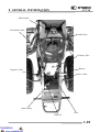
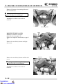
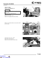
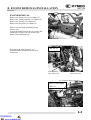
EXHAUST MUFFLER (MX’ER
50)
ATV 50
Nuts
Nuts
REMOVAL
Remove the two nuts attaching the exhaust
muffler.
Remove the two nuts attaching the exhaust
pipe.
Muffler
Remove the exhaust muffler lock bolts.
Remove the exhaust muffler and them
remove exhaust pipe.
When installing, first install the exhaust
pipe onto the engine and then install the
exhaust muffler.
Torque:
Exhaust muffler lock bolt:
3.3 kgf-m (33 N-m, 24 lbf-ft)
Bolt
Exhaust muffler joint lock nut:
1.2 kgf-m (12 N-m, 9 lbf-ft)
Bolt
* Be sure to install a new exhaust muffler
gasket.
Gasket
2-15
Exhaust Pipe
Gasket
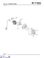
2. FRAME COVERS/EXHAUST MUFFLER
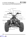
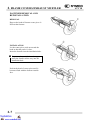
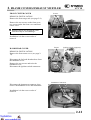
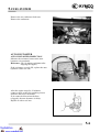
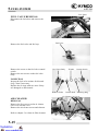
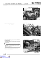
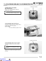
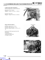
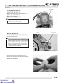
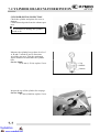
EXHAUST MUFFLER (MXU 50
REVERSE/MXU 50)
ATV 50
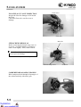
Nuts
REMOVAL
Remove the two nuts attaching the exhaust
pipe and cylinder head.
Remove the two bolts attaching the exhaust
muffler, then remove the exhaust muffler.
Bolt
Bolt
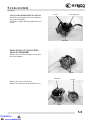
Inspect the gasket.
If the exhaust gas leaks, the gasket should
be replaced.
Install by reversing the removal sequence.
Torque:
Exhaust muffler lock bolt:
3.3 kgf-m (33 N-m, 24 lbf-ft)
Gasket
Exhaust muffler joint lock nut:
1.2 kgf-m (12 N-m, 9 lbf-ft)
* Be sure to install a new exhaust gasket.
2-16
3. INSPECTION/ADJUSTMENT
ATV 50
3
__________________________________________________________________________________
__________________________________________________________________________________
3
__________________________________________________________________________________
__________________________________________________________________________________
__________________________________________________________________________________
INSPECTION/ADJUSTMENT
__________________________________________________________________________________
SERVICE INFORMATION-----------------------------------------------MAINTENANCE SCHEDULE-------------------------------------------FUEL LINE/THROTTLE OPERATION/AIR CLEANER -----------SPARK PLUG/LUBRICATION SYSTEM -----------------------------CARBURETOR IDLE SPEED -------------------------------------------CYLINDER COMPRESSION/FINAL REDUCTION GEAR OIL --DRIVE BELT/BRAKE SHOE/BRAKE SYSTEM --------------------HEADLIGHT AIM ---------------------------------------------------------STEERING SYSTEM INSPECTION------------------------------------TOE-IN ADJUSTMENT --------------------------------------------------WHEELS/TIRES -----------------------------------------------------------DRIVE CHAIN SLACK ADJUSTMENT-------------------------------CABLE INSPECTION AND LUBRICATION-------------------------FRONT/REAR SUSPENSION LUBRICATION -----------------------
3- 1
3- 2
3- 3
3- 5
3- 7
3- 8
3-10
3-12
3-13
3-14
3-15
3-16
3-18
3-18
3-0
3. INSPECTION/ADJUSTMENT
ATV 50
SERVICE INFORMATION
GENERAL
! WARNING
•Before running the engine, make sure that the working area is well-ventilated. Never run the
engine in a closed area. The exhaust contains poisonous carbon monoxide gas which may
cause death to people.
•Gasoline is extremely flammable and is explosive under some conditions. The working area
must be well-ventilated and do not smoke or allow flames or sparks near the working area or
fuel storage area.
SPECIFICATIONS
ENGINE
Throttle grip free play : 1~4 mm (0.04 - 0.16 in)
Spark plug gap
: 0.6~0.7 mm (0.024 – 0.028 in)
Spark plug: Standard : NGK: BR8HAS
Idle speed
: 1800±100rpm
Gear oil capacity (MXU 50/MX’ER 50):
At disassembly : 0.12 liter (0.11 lmp qt, 0.13 Us qt)
At change
: 0.09 liter (0.08 lmp qt, 0.1 Us qt)
Gear oil capacity (MXU 50 REVERSE):
At disassembly : 0.3 liter (0.26 lmp qt, 0.32 Us qt)
At change
: 0.25 liter (0.22 lmp qt, 0.26 Us qt)
Cylinder compression: 1200 kPa (12 kgf/cm²,170 psi)
Ignition timing:
MXU 50/MX’ER 50: BTDC 22°/2000rpm
MXU 50 REVERSE: BTDC 13.5°/1500rpm
CHASSIS
Front brake free play: 10~20 mm (0.4 – 0.8 in)
Rear brake free play: 10~20 mm (0.4 – 0.8 in)
TIRE PRESSURE
Front
Rear
MX’ER 50 (1 Rider)
33 kPa (0.33 kgf/cm², 4.7 psi)
33 kPa (0.33 kgf/cm², 4.7 psi)
TIRE SIZE:
MX’ER 50:
Front: 20*7-8
Rear : 22*10-8
MXU 50 REVERSE/MXU 50
Front: 21*7-10
Rear : 22*10-10
3-1
MXU 50 REVERSEMXU 50 (1 Rider)
28 kPa (0.28 kgf/cm², 3.9 psi)
28 kPa (0.28 kgf/cm², 3.9 psi)
3. INSPECTION/ADJUSTMENT
TORQUE VALUES
Front wheel nut
Rear wheel nut
ATV 50
70 N-m (7 kgf-m, 50 lbf-ft)
70 N-m (7 kgf-m, 50 lbf-ft)
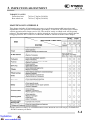
MAINTENANCE SCHEDULE
This chapter includes all information necessary to perform recommended inspections and
adjustments. These preventive maintenance procedures, if followed, will ensure more reliable
vehicle operation and a longer service life. The need for costly overhaul work will be greatly
reduced. This information applies to vehicles already in service as well as new vehicles that are
being prepared for sale. All service technicians should be familiar with this entire chapter.
• In the interest of safety, we recommend these items should be serviced only by an authorized
KYMCO motorcycle dealer.
3-2
3. INSPECTION/ADJUSTMENT
ATV 50
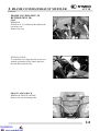
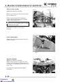
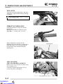
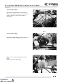
FUEL LINE
Check the fuel tubes and replace any parts,
which show signs of deterioration, damage
or leakage.
* Do not smoke or allow flames or sparks
in your working area.
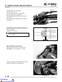
THROTTLE OPERATION
Fuel tube
Fuel Filter
Check the throttle to swing for smooth
movement.
Measure the throttle to swing free play.
Free Play: 1~4 mm (0.04 - 0.16 in)
Minor adjustment is made with the
adjusting nut at the throttle to swing above.
Slide the rubber cover out and adjust by
loosening the lock nut and turning the
adjusting nut.
Adjusting Nut
Lock Nut
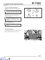
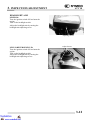
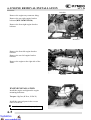
AIR CLEANER
Screws
AIR CLEANER REPLACEMENT
Remove five screws on the air cleaner case
cover and the cover.
Check the element and replace it if it is
excessively dirty or damaged.
Air Cleaner Case Cover
3-3
3. INSPECTION/ADJUSTMENT
ATV 50
CLEAN AIR FILTER ELEMENT
Wash the element gently, but thoroughly in
solvent.
* Use parts cleaning solvent only. Never
use gasoline or low flash point solvents
which may lead to a fire or explosion.
Squeeze the excess solvent out of the
element and let dry.
* Do not twist or wring out the foam
element. This could damage the foam
material.
Apply the engine oil.
Squeeze out the excess oil.
* The element should be wet but not
dripping.
CHANGE INTERVAL
More frequent replacement is required when
riding in unusually dusty or rainy areas.
Air Cleaner Element
3-4
3. INSPECTION/ADJUSTMENT
ATV 50
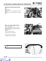
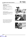
SPARK PLUG
Remove the spark plug
Check the spark plug for wear and fouling
deposits.
Clean any fouling deposits with a spark
plug
cleaner or a wire brush.
Specified Spark Plug: NGK-BR8HAS
Gap, Wear, and Fouling Deposits
Measure the spark plug gap.
Spark Plug Gap:
0.6~0.7 mm (0.024 – 0.028)
* When installing, first screw in the spark
plug by hand and then tighten it with a
spark plug wrench.
Washer Deformation
Clip
LUBRICATION SYSTEM
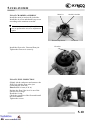
《Oil Filter Cleaning》
Disconnect the oil tube at the oil pump side
and allow oil to drain into a clean container.
Remove the tube clip at the oil tank side and
disconnect the oil tube.
Remove the oil filter.
Oil Filter
3-5
Cracks, Damage
3. INSPECTION/ADJUSTMENT
ATV 50
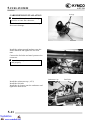
Clean the oil filter screen with compressed
air.
Install the oil filter in the reverse order of
removal and fill the oil tank with specified
oil up to the proper level.
Bleed air from the oil pump and oil lines.
Filter Screen
*• Connect the oil tubes securely.
• Install the tube clip at the oil tank side
and also install the clip to the lower oil
tube that goes to the oil pump.
• Check for oil leaks.
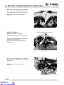
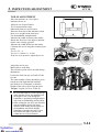
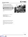
Control Aligning Mark
《Oil Pump Condition》
*
Adjust oil pump control cable after the
throttle grip free play is adjusted.
Open the throttle valve fully and check that
the index mark on the pump body aligns
with the aligning mark on the oil pump
control lever.
Reference tip alignment within 1mm of
index mark on open side is acceptable.
Start and idle the engine, then slowly open
the throttle to increase engine rpm and
check the operation of the oil pump control
lever.
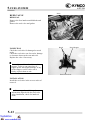
If adjustment is necessary, adjust the oil
pump control cable by loosening the control
cable lock nut and turning the adjusting nut.
After adjustment, tighten the lock nut.
Lock Nut
Adjusting Nut
*Reference tip alignment within 1mm of
index mark on open side is acceptable.
However, the aligning mark on the
control lever must never be on the
closed side of the index mark, otherwise
engine damage will occur because of
insufficient lubrication.
If the oil pump is not synchronized
properly,
the following will occur:
• Excessive white smoke or hard starting
due to pump control lever excessively open
• Seized piston due to pump control lever
insufficiently open.
3-6
3. INSPECTION/ADJUSTMENT
CARBURETOR IDLE SPEED
* • The engine must be warm for accurate
ATV 50
Throttle Stop Screw
idle speed inspection and adjustment.
Warm up the engine before this operation.
Start the engine and connect a tachometer.
Turn the throttle stop screw to obtain the
specified idle speed.
Idle Speed: 1800±100 rpm
When the engine misses or run erratic,
adjust the air screw.
Air Screw
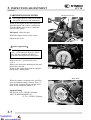
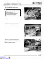
《Ignition Apparatus》
*The CDI ignition timing is not adjustable. If the timing is incorrect, check
the CDI unit, ignition coil and A.C.
generator and replace any faulty parts.
Remove the A.C. generator fan cover.
(Ö8-3)
Remove the four bolts attaching the fan and
then remove the fan.
Warm up the engine and check the ignition
timing with a timing light.
Bolts
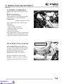
Index Mark
When the engine is running at the specified
rpm, the ignition timing is correct if the “F”
mark on the flywheel aligns with the index
mark on the crankcase within ±1.5°.
Ignition Timing:
MX’ER 50: 22°±1.5°BTDC/2000rpm
MXU 50 REVERSE/MXU 50:
13.5°±1.5°BTDC/1500rpm
“F” Mark
3-7
3. INSPECTION/ADJUSTMENT
ATV 50
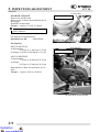
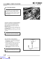
CYLINDER COMPRESSION
Warm up the engine before compression
test.
Remove the spark plug.
Insert a compression gauge.
Open the throttle valve fully and push the
starter button to test the compression.
Compression:
1200kPa (12kgf/cm²,170psi)
If the compression is low, check for the
following:
- Leaky valves
- Valve clearance too small
- Leaking cylinder head gasket
- Worn piston rings
- Worn piston/cylinder
If the compression is high, it indicates that
carbon deposits have accumulated on the
combustion chamber and the piston head.
Compression Gauge
Oil Check Bolt
FINAL REDUCTION GEAR OIL
MXU 50/MX’ER 50
MXU 50/MX’ER 50: Gear Oil Lever
The gear oil level shall be at the oil check
bolt hole. If the oil level is low, add the
specified oil to the proper level.
Specified Gear Oil: SAE10W90#
Install and tighten the oil check bolt.
Torque: 1.3 kgf-m (13 N-m, 9.4 lbf-ft)
Start the engine and check for oil leaks.
3-8
3. INSPECTION/ADJUSTMENT
ATV 50
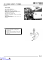
Oil Filler Bolt
GEAR OIL CHANGE
Remove the oil filler bolt.
Removes the oil drains bolt and drain the oil
thoroughly.
Install the oil drain bolt.
Torque: 1.3 kgf-m (13 N-m, 9.4 lbf-ft)
MXU 50/MX’ER 50
* Make sure that the sealing washer is in
good condition.
Fill with the recommended oil.
Specified Gear Oil:
SAE10W90#
Oil Capacity:
MXU 50/MX’ER 50
At disassembly:
0.12 liter (0.11 lmp qt,0.13 Us qt)
At change: 0.09 liter (0.08 lmp qt,0.1 Us qt)
Oil Drain Bolt/ Sealing Washer
Oil Filler Bolt
MXU 50 REVERSE
MXU 50 REVERSE
At disassembly:
0.3 liter (0.26 lmp qt,0.32 Us qt)
At change:
0.25 liter (0.22 lmp qt,0.26 Us qt)
Reinstall the oil filler bolt and check for oil
leaks.
Torque: 1.3 kgf-m (13N-m, 9.4 lbf-ft)
Oil Drain Bolt/ Sealing Washer
3-9
3. INSPECTION/ADJUSTMENT
ATV 50
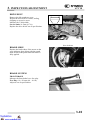
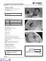
DRIVE BELT
Remove the left crankcase cover.
Inspect the drive belt for cracks, scaling,
chipping or excessive wear.
Measure the V-belt width
Service limit: 16.5mm (0.7 in)
Replace the drive belt if out of specification.
Drive Belt
BRAKE SHOE
Wear Indicator
Replace the brake shoes if the arrow on the
wear indicator plate aligns with the punch
mark on the brake panel when the brake is
fully applied.
Punch Mark
BRAKE SYSTEM
FRONT BRAKE
Measure the front brake lever free play.
Free Play: 10~20 mm (0.4 – 0.8 in)
Adjust if out of specification.
3-10
3. INSPECTION/ADJUSTMENT
ATV 50
Adjusters
Adjust brake lever free play:
Loosen the lock nuts.
Turn the adjusters in or out until the
specified free play is obtained.
Turning adjusters in that the free play is
increased.
Turning adjusters out that the free play is
decreased.
Lock Nuts
The difference between both clearances
should be 2 mm (0.08 in)or less when front
brake is applied.
Tighten the lock nuts.
* Make sure that the brake does not drag
after adjusting.
REAR BRAKE (drum brake)
Measure the rear brake lever free play.
Free Play: 10~20 mm (0.4 – 0.8 in)
If the free play do not fall within the limit,
adjust by turning the adjusting nut.
Adjusting Nut
3-11
3. INSPECTION/ADJUSTMENT
ATV 50
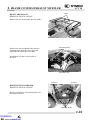
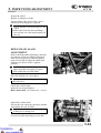
HEADLIGHT AIM
MX’ER 50:
Turn the ignition switch ON and start the
engine.
Turn on the headlight switch.
Adjust the headlight aim by turning the
headlight aim adjusting screw.
Adjusting Screw
MXU 50 REVERSE/MXU 50:
Turn the ignition switch ON and start the
engine.
Turn on the headlight switch.
Adjust the headlight aim by turning the
headlight aim adjusting screws.
Adjust Screws
3-12
3. INSPECTION/ADJUSTMENT
ATV 50
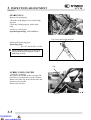
STEERING SYSTEM
INSPECTION
Place the machine on a level place.
Check the steering column bushings and
bearings:
Move the handlebar up and down, and/or
back and forth.
Replace the steering column bushings and
or bearings if excessive play
Check the tie-rod ends
Turn the handlebar to the left and/or right
until it stops completely, then slightly move
the handlebar from left to right.
Replace the tie-rod ends if tie-rod end has
any vertical play.
Raise the front end of the machine so that
there is no weight on the front wheels.
Check ball joints and/or wheel bearings.
Move the wheels lately back and forth.
Replace the front arms and/or wheel
bearings if excessive free play.
3-13
Tie-rod Ends
3. INSPECTION/ADJUSTMENT
TOE-IN ADJUSTMENT
Place the machine on a level place.
Measure the toe-in
Adjust if out of specification.
Toe-in measurement steps:
Mark both front tire tread centers.
Raise the front end of the machine so that
there is no weight on the front tires.
Fix the handlebar straight ahead.
Measure the width A between the marks.
Rotate the front tires 180 degrees until the
marks come exactly opposite.
Measure the width B between the marks.
Calculate the toe-in using the formula given
below.
Toe-in = B-A
Toe-in: 0~10mm ( 0 – 0.4 in)
If the toe-in is incorrect, adjust the toe-in
Adjust the toe-in step:
Mark both tie-rods ends.
This reference point will be needed during
adjustment.
Loosen the lock nuts (tie-rod end) of both
tie-rods
The same number of turns should be given
to both tie-rods right and left until the
specified toe-in is obtained, so that the
lengths of the rods will be kept the same.
Torque: 3 kgf-m (30 N-m, 22 lbf-ft)
* • Be sure that both tie-rod are turned the
ATV 50
A
B
Tie-rod
Tie-rod End Nuts
same amount. If not, the machine will
drift tight or left even though the
handlebar is positioned straight which
may lead to mishandling and accident.
• After setting the toe-in to specification,
run the machine slowly for some
distance with hands placed lightly on
the handlebar and check that the
handlebar responds correctly. If not,
turn either the right or left tie-rod
within the toe-in specification.
3-14
3. INSPECTION/ADJUSTMENT
ATV 50
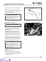
WHEELS/TIRES
Check the tires for cuts, imbedded nails or
other damages.
Check the tire pressure.
* Tire pressure should be checked when
tires are cold.
TIRE PRESSURE
Front Axle Nut
Front/Rear (1 Rider)
MX’ER 50
0.33 kgf/cm² (33 kPa, 4.7 psi)
MXU 50
0.28 kgf/cm² (28 kPa, 3.9 psi)
TIRE SIZE
MXU 50 REVERSE/MXU50:
Front: 21*7-10
Rear: 22*10-10
MX’ER 50:
Front: 20*7-8
Rear: 22*10-8
Check the front axle nut for looseness.
Check the rear axle nut for looseness.
If the axle nuts are loose, tighten them to the
specified torque.
Torque:
Front : 7 kgf-m (70 N-m, 50 lbf-ft)
Rear : 7 kgf-m (70 N-m, 50 lbf-ft)
WHEEL INSPECTION
Inspect the tire surfaces.
Replace if wear or damage.
Tire wear limit: 3 mm (0.1 in)
* It is dangerous to ride with a worn out
tire. When a tire wear is out of
specification, replace the tire
immediately.
3-15
Rear Axle Nut
3. INSPECTION/ADJUSTMENT
ATV 50
Inspect the wheel.
Replace if damage or bends
Always balance the wheel when a tire or
wheel has been changed or replaced.
* • Never attempt even small repairs to the
wheel.
• Ride conservatively after installing a
tire to allow it to seat itself properly on
the rim.
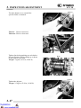
DRIVE CHAIN SLACK
ADJUSTMENT
Before checking and/or adjusting, rotate the
rear wheels several revolutions and check
slack at several points to find the tightest
point. Check and/or adjust the chain slack
with the rear wheels in this “tightest”
position.
* Too little of chain slack will overload the
engine and other vital parts; keep the
slack within the specified limits.
Place the machine on a level place.
* Wheels should be on the ground without
the rider on it.
Check drive chain slack.
Adjust if out of specification.
Drive chain slack: 10-20 mm (0.4 – 0.8 in)
Bolts
Adjust drive chain slack:
Elevate the rear wheels by placing a suitable
stand under the rear of frame.
* Support the machine securely so there is
no danger of it falling over.
Loosen four bolts attaching rear axle hub.
3-16
3. INSPECTION/ADJUSTMENT
ATV 50
Adjuster
Turn the adjuster in or out until the
specified slack is obtained.
Turn in: Slack is increased.
Turn out: Slack is decreased.
Tighten four bolts attaching rear axle hub to
the specification. While pushing up or down
on the chain to zero slack.
Torque: 7 kgf-m (70 N-m, 50 lbf-ft)
Bolts
Adjuster
Tighten the adjuster.
Torque: 2.2 kgf-m (22 N-m, 16 lbf-ft)
3-17
3. INSPECTION/ADJUSTMENT
ATV 50
CABLE INSPECTION AND
LUBRICATION
* Damaged cable sheath may cause
corrosion and interfere with the cable
movement. An unsafe condition may
result so replace such cable as soon as
possible.
Inspect the cable sheath.
Replace if damage.
Check the cable operation.
Lubricate or replace if unsmooth operation.
* Hold cable end high and apply several
drops of lubricant to cable.
LEVER LUBRICATION
Lubricate the pivoting parts of each lever.
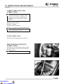
FRONT/REAR SUSPENSION
LUBRICATION
Inject grease into the nipples using a grease
gun until slight over flow is observed from
the thrust covers.
* Wipe off the excess grease.
Nipple
3-18
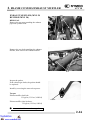
4. LUBRICATION SYSTEM
ATV 50
4
__________________________________________________________________________________
__________________________________________________________________________________
__________________________________________________________________________________
4
__________________________________________________________________________________
__________________________________________________________________________________
LUBRICATION SYSTEM
__________________________________________________________________________________
SERVICE INFORMATION ................................................................ 4-2
TROUBLESHOOTING ....................................................................... 4-2
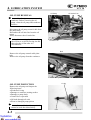
OIL PUMP REMOVAL....................................................................... 4-3
OIL PUMP INSPECTION ................................................................... 4-3
OIL PUMP INSTALLATION ............................................................. 4-4
OIL PUMP BLEEDING....................................................................... 4-5
OIL TANK ........................................................................................... 4-6
4-0
4. LUBRICATION SYSTEM
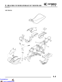
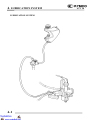
LUBRICATION SYSTEM
4-1
ATV 50
4. LUBRICATION SYSTEM
ATV 50
SERVICE INFORMATION
GENERAL INSTRUCTIONS
• Use care when removing and installing the oil pump not to allow dust and dirt to enter the engine
and oil line.
• Do not attempt to disassemble the oil pump.
• Bleed air from the oil pump if there is air between the oil pump and oil line.
• If the oil is disconnected, refill the oil line with motor oil before connecting it.
SPECIFICATIONS
• Recommended Motor Oil: SAE20W20# 2-stroke Motor Oil
• Oil Capacity
: 1 liter (0.88 lmp qt, 1.06 Us qt)
Light comes on : 0.25 liter (0.22 lmp qt, 0.27 Us qt)
TROUBLESHOOTING
Excessive white smoke or carbon deposits on spark plug
• Oil pump not properly synchronized (excessive oil)
• Poor quality oil
Engine overheating
• Oil pump not properly adjusted (insufficient oiling)
• Poor quality oil
Seized piston
• No oil in tank or clogged oil line
• Oil pump not properly adjusted (insufficient oiling)
• Air in oil line
• Faulty oil pump
Oil not flowing out of tank to engine
• Clogged oil tank cap breather hole
• Clogged oil filter
4-2
4. LUBRICATION SYSTEM
OIL PUMP REMOVAL
ATV 50
Oil Outlet Line
Oil Pump
* Do not allow foreign matters to enter the
crankcase. Before removing the oil
pump, clean the oil pump and crankcase
surfaces.
Disconnect the oil pump control cable from
the pump body.
Disconnect the oil inlet line from the oil
pump.
Then, disconnect the oil outlet line.
*
Before disconnecting the oil line, clip
the oil line to avoid oil flowing out and
then plug the oil line after it is
disconnected.
Oil Inlet Line
Control Cable
Bolt
Remove the oil pump control cable plate
bolt.
Remove the oil pump from the crankcase.
Control Cable plate
O-ring
OIL PUMP INSPECTION
Remove the oil pump and inspect the
following items:
• Weakened O-ring
• Damage to crankcase mating surface
• Damage to pump body
• Control lever operation
• Oil leaks through oil seals
• Worn or damaged pump pinion
*
Do not disassemble the oil pump which
cannot be used after disassembly.
Gear
4-3
Control Lever
4. LUBRICATION SYSTEM
ATV 50
OIL PUMP INSTALLATION
*
• Lubricate the O-ring with grease or
engine oil before installation.
• Make sure that the oil pump is inserted
into the crankcase.
• Apply molybdenum disulfide or
grease to the pump pinion.
Grease or Engine Oil
Bolts
Install the oil pump onto the crankcase.
Nut
Oil Outlet Line
Install the oil pump control cable plate.
Connect the oil inlet line and oil outlet line
properly.
Connect the oil pump control cable.
Bleed air from the oil pump.
Oil Pump Driven Gear
Oil Inlet Line
Control Cable
4-4
4. LUBRICATION SYSTEM
ATV 50
Oil Outlet Line
OIL PUMP BLEEDING
*
• Air in the oil lines will block oil flow
and result in severe engine damage.
• Bleed air from the oil lines and oil
pump whenever the oil lines or pump
have been removed or there is air in
the oil lines.
Oil Pump
OIL INLET LINE/OIL PUMP BLEEDING
Fill the oil tank with recommended oil.
Place a shop towel around the oil pump.
Disconnect the oil inlet line from the oil
pump and clip it.
Fill the oil pump with oil by squirting clean
oil through the joint. (About 3cc, 0.003 lmp
qt, 0.003 Us qt)
Fill the oil line with oil and connect it to the
oil pump.
*
Bleed air from the oil inlet line first,
then bleed air from the oil outlet line.
OIL OUTLET LINE BLEEDING
1. Disconnect the oil outlet line and bend it
into U shape. Force air out of the tube
by filling it with oil.
2. Start the engine and allow it to idle with
the oil control lever in the fully open
position. Visually check the oil flow.
3. If there is no oil flowing out within 1
minute, bleed air from the oil inlet line
and oil pump.
*
Oil Outlet Line
• Never run the engine in a closed area.
• Do not increase the engine speed at
will.
4-5
4. LUBRICATION SYSTEM
ATV 50
Wire Connector
OIL TANK
OIL TANK REMOVAL
Remove the seat. (Ö2-3 or 2-8)
Remove the oil meter connector.
Remove the one bolt and one nut from the
oil tank. (see page 2-14)
Disconnect the oil inlet line.
Drain the oil inside the oil tank into a clean
container.
Remove the oil tank.
The installation sequence is the reverse of
removal.
Dowel Pin
Pump Cover
* • Connect the oil line properly.
• Bleed air from the oil pump after
installation.
• The oil tube clip (at the oil tank side)
must be locked from inside of the oil
tube joint.
4-6
5. FUEL SYSTEM
ATV 50
5
__________________________________________________________________________________
__________________________________________________________________________________
__________________________________________________________________________________
5
__________________________________________________________________________________
__________________________________________________________________________________
FUEL SYSTEM
__________________________________________________________________________________
SERVICE INFORMATION-----------------------------------------------TROUBLESHOOTING----------------------------------------------------THROTTLE VALVE DISASSEMBLY/CARBURETOR REMOVAL-AUTO BYSTARTER ------------------------------------------------------FLOAT/FLOAT VALVE/JETS/FLOAT CHAMBER-----------------CARURETOR INSTALLATION ----------------------------------------AIR SCREW ADJUSTMENT --------------------------------------------REED VALVE --------------------------------------------------------------FUEL TANK ----------------------------------------------------------------FUEL VALVE REMOVAL -----------------------------------------------AIR CLEANER --------------------------------------------------------------
5- 2
5- 2
5- 3
5- 6
5- 8
5-11
5-12
5-13
5-14
5-15
5-15
5-0
5. FUEL SYSTEM
5-1
ATV 50
5. FUEL SYSTEM
ATV 50
SERVICE INFORMATION
GENERAL INSTRUCTIONS
• When working with gasoline, keep away from sparks and flames..
• Note the locations of O-rings when disassembling and replace them with new ones during
assembly.
• All cables, fuel lines and wires must be routed and secured at correct locations.
• Bleed air from the oil lines whenever they are disconnected.
SPECIFICATIONS
Venturi dia.
Identification number
Float level
Main jet
ATV 50
14 mm (0.56 in)
PB
8.6 mm (0.34 in)
# 80
Slow jet
Air screw opening
Idle speed
Throttle grip free play
# 38S
2 ± 1/2
1800±100 rpm
1~4 mm (0.04 – 0.16 in)
SPECIAL TOOL
Float level gauge
TROUBLESHOOTING
Engine does not start
• No fuel in tank
• Too much fuel getting to cylinder
• Clogged fuel filter
• Clogged air cleaner
Lean mixture
• Clogged fuel jets
• Faulty float valve
• Clogged fuel cap vent
• Float level too low
• Clogged fuel filter
• Clogged air cleaner
• Bent, kinked or restricted fuel line
Engine idles roughly, stalls or runs poorly
• Incorrect idle speed
• Clogged air cleaner
• Ignition malfunction
• Intake air leaks
• Compression too low
• Fuel contaminated
• Incorrectly adjusted air screw
• Faulty reed valve
• Incorrect float level
• Clogged fuel jets
Rich mixture
• Faulty float valve
• Float level too high
• Clogged air jets
5-2
5. FUEL SYSTEM
ATV 50
Carburetor Cap
THROTTLE VALVE DISASSEMBLY/CARBURETOR
REMOVAL
Loosen the carburetor cap and remove the
throttle valve.
Disconnect the throttle cable from the
throttle valve.
Throttle Valve
Carburetor Cap
Remove the throttle valve spring, carburetor
cap and rubber seal.
Spring
5-3
Rubber Seal
5. FUEL SYSTEM
ATV 50
Remove the jet needle by removing the
needle clip.
Check the jet needle and throttle valve for
wear or damage.
Needle Clip
Needle Retainer
2nd Notch (STD)
Jet Needle
Throttle Valve
Carburetor Cap
Rubber Seal
THROTTLE VALVE INSTALLA-TION
Install the jet needle on the throttle valve and
secure with the needle clip.
Install the rubber seal on the throttle cable
and then install the carburetor cap and
throttle valve spring.
Throttle Valve Spring
Connect the throttle cable to the throttle
valve.
Throttle Valve
Throttle Cable
5-4
5. FUEL SYSTEM
ATV 50
Groove
Install the throttle valve by aligning the
groove in the throttle valve with the throttle
stop screw.
Tighten the carburetor cap.
After installation, perform the following
adjustments and inspections.
• Throttle cable free play (Ö3-3)
• Idle speed adjustment (Ö3-7)
Carburetor Cap
Throttle Cable
Bystarter
Fuel Tube
CARBURETOR REMOVAL
Remove the air cleaner by removing the air
cleaner band screw and attaching bolts.
Disconnect the fuel tube.
Loosen the drain bolt to drain fuel from the
carburetor.
Disconnect the auto bystarter wire
connector.
Drain Bolt
5-5
Band
5. FUEL SYSTEM
ATV 50
Remove the two carburetor lock nuts.
Remove the carburetor.
Nuts
AUTO BYSTARTER
AUTO BYSTARTER INSPECTION
Measure the resistance between the auto
bystarter wire terminals.
Resistance: 5Ω (10 minutes minimum after
stopping the engine)
If the resistance exceeds 5Ω, replace the auto
bystarter with a new one.
After the engine stops for 30 minutes,
connect a hose to the fuel enriching circuit
and blow the hose with mouth.
If air cannot be blown into the hose
(clogged), the auto bystarter is faulty.
Replace it with a new one.
5-6
5. FUEL SYSTEM
ATV 50
Connect the auto bystarter yellow wire to the
battery positive (+) terminal and green/ black
wire to the battery negative (-) terminal and
wait 5 minutes.
Connect a hose to the fuel enriching circuit
and blow the hose with mouth.
If air can be blown into the hose, the auto
bystarter is faulty and replace it with a new
one.
Auto Bystarter
AUTO BYSTARTER REMOVAL
Remove the auto bystarter cover.
Remove the two auto bystarter set plate
screws to remove the auto bystarter.
Screws
Check the auto bystarter valve and needle for
wear or damage.
Check the O-ring for wear or damage.
O-ring
Bystarter Valve
5-7
Set Plate
Bystarter Needle
5. FUEL SYSTEM
AUTO BYSTARTER INSTALLATION
Install the auto bystarter into the carburetor
body until it bottoms..
Install the set plate and then tighten the two
screws.
ATV 50
Screws
Auto Bystarter
Set Plate
FLOAT/FLOAT VALVE/JETS
FLOAT CHAMBER
Remove the two float chamber screws and
the float chamber.
Screws
Float Pin
O-ring
Remove the screw and O-ring.
Remove the float pin, float and float valve.
Float
5-8
5. FUEL SYSTEM
FLOAT/FLOAT VALVE INSPECTION
Inspect the float for damage or fuel inside
the float.
Check the float valve seat for wear or
damage.
ATV 50
Float Valve
Float Seat
Main Jet
JETS/SCREWS REMOVAL
Before removing the throttle stop screw or
air screw, record the number of rotations
until it seats lightly. Then, remove them.
* Do not force the air screw against its
seat to prevent damage.
Remove the main jet and needle jet holder.
Throttle Stop Screw
CARBURETOR PASSAGES CLEANING
Blow compressed air through all passages of
the carburetor body with an air gun.
5-9
Air Screw
5. FUEL SYSTEM
FLOAT CHAMBER ASSEMBLY
Install the main jet and needle jet holder.
Install the air screw and throttle stop screw
according to the rotations recorded.
ATV 50
Main Jet
Needle Jet holder
* If the air screw must be replaced, be
sure to perform the air screw adjustment
again.
Throttle Stop Screw
Install the float valve, float and float pin.
Tighten the float screw securely.
Air Screw
Float Pin
FLOAT LEVEL INSPECTION
Slightly tilt the carburetor and measure the
float level with the float valve just
connecting the float arm.
Float Level: 8.6 mm (0.34 in)
Replace the float if the level is out of the
specified level range.
Install the O-ring.
Check the operation of the float and install
the float chamber.
Tighten the screws.
5-10
5. FUEL SYSTEM
ATV 50
O-rings
CARBURETOR INSTALLATION
* When installation, do not allow foreign
particles to enter the carburetor.
Check the carburetor insulator and O-ring
for wear or damage.
Insulator
Install the carburetor and insulator onto the
intake manifold and tighten the two lock
nuts.
Connect the fuel tube and auto bystarter wire
connector.
* Route the auto bystarter wire correctly
and properly.
Nuts
Carburetor Cap
Fuel Tube
Install the carburetor cap. (Ö5-3)
Install the fuel tube
Install the air cleaner onto the carburetor and
tighten the band screw.
Band
5-11
5. FUEL SYSTEM
AIR SCREW ADJUSTMENT
ATV 50
Air Screw
Turn the air screw clockwise until it seats
lightly and back it to the specification given.
* Do not force the air screw against its
seat to prevent damage.
Start the engine and turn the air screw in or
out slowly to obtain the highest engine
speed.
Throttle Stop Screw
Turn the throttle stop screw to obtain the
specified idle speed.
Idle Speed: 1800±100 rpm
Air Screw Opening: 2 ± 1/2 turns
Slightly increase the engine speed and make
sure that the engine does not miss or run
erratic.
If the adjustment of the air screw within the
range of ±1/2 turn makes no difference to the
engine performance, check other related
items.
5-12
5. FUEL SYSTEM
REED VALVE
ATV 50
Bolts
REMOVAL
Remove the four intake manifold bolts and
gasket.
Remove the reed valve and gasket.
Intake Manifold
INSPECTION
Check the reed valve for damaged or weak
reeds.
Check the reed valve seat for cracks, damage
or clearance between the seat and reed.
Replace the valve if necessary.
Reeds
Reed Stopper
*
Do not disassemble or bend the reed
stopper. To do so can cause loss of
engine power and engine damage. If any
of the stopper, reed or valve seat is
faulty, replace them as unit.
Reed Valve Seat
INSTALLATION
Install the reed valve in the reverse order of
removal.
*
Install a new gasket with the gasket
indentation aligned with the reed valve.
After installation, check for intake air
leaks.
5-13
5. FUEL SYSTEM
FUEL TANK
ATV 50
Lever
Seat
FUEL TANK REMOVAL
Warning
• Keep sparks and flames away from the
work area.
• Wipe off any spilled gasoline.
Remove the seat.
Remove the center cover.
Remove the right and left front fender.
Screws
Bolts
Remove two bolts and two nuts on the end of
the fuel tank.
nuts
Center Cover
Fuel Tank
Fuel Tubes
Switch the fuel valve “OFF”.
Disconnect the fuel tubes.
Remove the fuel tank and fuel valve.
Fuel Valve
5-14
5. FUEL SYSTEM
ATV 50
Fuel Tubes
FUEL VALVE REMOVAL
Disconnect the fuel tubes and remove the
bolts.
Fuel Valve
Remove the fuel valve and fuel cup.
Remove the screw on the fuel valve control
switch.
Remove the two screws on the fuel valve
body.
Fuel Valve
Fuel Valve Body
Washer
Control Switch
INSPECTION
Inspect the fuel valve strainer for dirt and
clog. Clean if necessary.
Replace the O-rings with new ones if they
are damaged or deteriorated.
Rubber Gasket
Control Shaft Retaining Ring
Air Cleaner Case Cover
AIR CLEANER
REMOVAL
Remove the five screws on the air cleaner
case cover and the cover.
Remove the air cleaner screen and element.
Refer to chapter 3 to clean air filter element.
Screws
5-15
6. ENGINE REMOVAL/INSTALLATION
ATV 50
6
__________________________________________________________________________________
__________________________________________________________________________________
__________________________________________________________________________________
__________________________________________________________________________________
__________________________________________________________________________________
6
ENGINE REMOVAL/INSTALLATION
__________________________________________________________________________________
SERVICE INFORMATION------------------------------------------------ 6- 1
ENGINE REMOVAL ------------------------------------------------------- 6- 2
ENGINE INSTALLATION ------------------------------------------------ 6- 5
6-0
6. ENGINE REMOVAL/INSTALLATION
SERVICE INFORMATION
GENERAL INSTRUCTIONS
• A floor jack or other adjustable support is required to support and maneuver the engine.
Be careful not to damage the machine body, cables and wires during engine removal.
• Use shop towels to protect the motorcycle body during engine removal.
• Parts requiring engine removal for servicing:
⎯ Crankcase
⎯ Crankshaft
6-1
ATV 50
6. ENGINE REMOVAL/INSTALLATION
ATV 50
Band
ENGINE REMOVAL
Remove the frame covers (see chapter 2).
Remove the exhaust muffler (see chapter 2).
Remove the oil tank (see chapter 4)
Remove the fuel tank (see chapter 5).
Remove the two bolts attaching the air
cleaner case.
Loosen the band between the air cleaner and
carburetor to remove the air cleaner case.
Remove the carburetor cap.
Carburetor Cap
Bolts
A.C.Generator/Pulser Wire Connector
Disconnect the auto bystarter, A.C.
generator/pulser and starter motor wire
connectors.
MX’ER 50
Auto Bystarter
Wire Connector
Starter Motor
Wire Connector
A.C.Generator Wire Connectors
MXU 50 REVERSE
MXU 50
Pulser Wire Connectors
6-2
6. ENGINE REMOVAL/INSTALLATION
ATV 50
Starter Motor Wire Connector
MXU 50 REVERSE
MXU 50
Auto Bystarter Wire Connector
Spark Plug Cap
Remove the spark plug cap.
Disconnect the oil pump control cable from
the pump body.
Disconnect the oil inlet and outlet line from
the oil pump.
*
Oil Outlet Line
Carburetor Lock Nuts
After the oil inlet line is disconnected,
plug the oil line opening to prevent oil
from flowing out.
Remove the two carburetor lock nuts.
Remove the carburetor.
Oil Inlet Line
6-3
Control Cable
6. ENGINE REMOVAL/INSTALLATION
MXU 50 REVERSE:
ATV 50
Drive Select Rod
Neutral Switch Connectors
Disconnect the neutral switch connectors.
Remove the bolt/nut at drive select rod, then
remove the drive select rod from drive
select arm.
Bolt/Nut
Drive Select Arm
Bolts
MXU 50 REVERSE:
Remove the three bolts at the drive sprocket
cover, then remove the protector cover.
Drive Sprocket Cover
Drive Chain Gear
Remove the rear drive chain gear on the
bolts.
Remove the drive chain gear.
Bolts
6-4
6. ENGINE REMOVAL/INSTALLATION
ATV 50
Bolt/Nut
Remove the engine any connector thing.
Remove the rear right engine bracket
bolt/nut (MXU 50/MX’ER 50).
Remove the front right engine bracket
bolt/nut.
Bolt/NUT
Remove the front left engine bracket
bolt/nut.
Remove the rear left engine bracket
bolt/nut.
Remove the engine to the right side of the
frame.
Bolt/Nut
ENGINE INSTALLATION
Install the engine and tighten the engine
mounting bolts/nuts.
Torque: 4 kgf-m (40 N-m, 29 lbf-ft)
Install the removed parts in the reverse
order of removal.
* Route the wires and cables properly.
6-5
Bolt/Nut
7. CYLINDER HEAD/CYLINDER/PISTON
ATV 50
7
__________________________________________________________________________________
__________________________________________________________________________________
__________________________________________________________________________________
__________________________________________________________________________________
__________________________________________________________________________________
CYLINDER HEAD/CYLINDER/PISTON
__________________________________________________________________________________
7
SERVICE INFORMATION------------------------------------------------ 7-2
TROUBLESHOOTING----------------------------------------------------- 7-2
CYLINDER HEAD---------------------------------------------------------- 7-3
CYLINDER/PISTON ------------------------------------------------------- 7-6
7-0
7. CYLINDER HEAD/CYLINDER/PISTON
7-1
ATV 50
7. CYLINDER HEAD/CYLINDER/PISTON
ATV 50
SERVICE INFORMATION
GENERAL INSTRUCTIONS
• The cylinder head, cylinder and piston can be serviced with the engine installed in the frame.
• Before disassembly, clean the engine to prevent dust from entering the engine.
• Remove all gasket material from the mating surfaces.
• Do not use a driver to pry between the cylinder and cylinder head, cylinder and crankcase.
• Do not damage the cylinder inside and the piston surface.
• After disassembly, clean the removed parts before inspection. When assembling, apply the
specified engine oil to movable parts.
SPECIFICATIONS
Unit: mm (in)
Standard
⎯
Item
Cylinder head warpage
Piston O.D.(5mm from bottom of piston skirt)
Cylinder-to- piston clearance
Piston pin hole I.D.
Piston pin O.D.
Piston-to-piston pin clearance
Piston ring end gap (top/second)
Connecting rod small end I.D.
Cylinder bore
TORQUE VALUES
Cylinder head bolt
Exhaust muffler joint lock nut
Exhaust muffler lock bolt
Spark plug
Service Limit
0.1 (0.004)
38.97 (1.5588).~38.955 (1.5582)
38.9 (1.556)
0.03 (0.0012)~0.07 (0.0028)
0.1 (0.004)
12.002 (0.48008)~12.008 (0.48032)
12.03 (0.4812)
11.994 (0.47976)~12 (0.48)
11.98 (0.4792)
0.002 (0.00008)~0.014 (0.00056)
0.03 (0.0012)
0.1 (0.004)~0.25 (0.01)
0.4 (0.016)
17.005 (0.6802)~17.017 (0.68068)
17.03 (0.6812)
39 (1.56)~39.025 (1.561)
39.05 (1.562)
1.6 kgf-m (16 N-m, 11.5 lbf-ft)
1.2 kgf-m (12 N-m, 8.6 lbf-ft)
3.3 kgf-m (33 N-m, 23.8 lbf-ft)
1.4 kgf-m (14 N-m, 10.1 lbf-ft)
TROUBLESHOOTING
Compression too low, hard starting
or poor performance at low speed
• Leaking cylinder head gasket
• Loose spark plug
• Worn, stuck or broken piston and piston rings
• Worn or damaged cylinder and piston
Compression too high, overheating
or knocking
• Excessive carbon build-up in cylinder head
or on piston head
Abnormal noisy piston
• Worn cylinder and piston
• Worn piston pin or piston pin hole
• Worn connecting rod small end bearing
Abnormal noisy piston rings
• Worn, stuck or broken piston rings
• Worn or damaged cylinder
7-2
7. CYLINDER HEAD/CYLINDER/PISTON
ATV 50
Spark Plug Cap
CYLINDER HEAD
REMOVAL
Remove the spark plug cap.
Remove the exhaust muffler. (Ö2-15 or 216)
Bolts
Remove the three bolts attaching the fan
cover to remove the fan cover.
Remove the bolt attaching the engine hood
to remove the engine hood.
The installation sequence is the reverse of
removal.
Fan Cover/Engine Hood
Cylinder Head
Cylinder head Bolts
Remove the spark plug.
Remove the cylinder head bolts and the
cylinder head.
*
Loosen the bolts diagonally in 2 or 3
times.
Remove the cylinder head gasket.
Spark Plug
7-3
7. CYLINDER HEAD/CYLINDER/PISTON
ATV 50
Combustion Chamber
COMBUSTION CHAMBER
DECABONIZING
Remove the carbon deposits from the
combustion chamber
*
Avoid damaging the combustion chamber wall and cylinder mating surface.
Mating Surface
CYLINDER HEAD INSPECTION
Check the cylinder head for warpage with a
straight edge and feeler gauge.
Service Limit:
0.1 mm (0.004 in) replace if over
Cylinder head Gasket
CYLINDER HEAD INSTALLATION
Install the cylinder head on the cylinder
properly.
*
Be careful not to damage the mating
surfaces.
Install a new cylinder head gasket onto the
cylinder.
7-4
7. CYLINDER HEAD/CYLINDER/PISTON
Cylinder Head Bolts Installation
ATV 50
Cylinder head Bolts
Install and tighten the cylinder head bolts
diagonally in 2 or 3 times.
Torque: 1.6 kgf-m (16 N-m, 11.5 lbf-ft)
Install the spark plug.
Torque: 1.4 kgf-m (14 N-m, 10.1 lbf-ft)
Cylinder Head
Spark Plug
Engine Hood
Engine Hood Installation
Install the engine hood. (Ö7-3)
Install the spark plug cap. (Ö7-3)
Install the exhaust muffler. (Ö12-15 or 1216)
Perform the following inspections after
installation:
• Compression test
• Abnormal engine noise
• Cylinder air leaks
Bolt
Spark Plug
Bolts
7-5
7. CYLINDER HEAD/CYLINDER/PISTON
ATV 50
Cylinder
CYLINDER/PISTON
CYLINDER REMOVAL
Remove the reed valve (seep page 5-13).
Remove the cylinder head.
Remove the cylinder.
Remove the cylinder gasket.
*
Do not pry between the cylinder and
crankcase or strike the fins.
PISTON REMOVAL
Remove the piston pin clip to remove the
piston pin and piston.
Piston
Piston Pin
*• Do not damage or scratch the piston.
• Do not apply side force to the connecting rod when removing the piston pin.
• Place clean shop towels in the crankcase to keep the piston pin clip from
falling into the crankcase.
Piston Pin Clip
Spread each piston ring and remove by
lifting it up at a point just opposite the gap.
Remove the expander.
7-6
7. CYLINDER HEAD/CYLINDER/PISTON
ATV 50
CYLINDER/PISTON INSPECTION
Check the cylinder and piston for wear or
damage.
Clean carbon deposits from the exhaust port
area.
*
Be careful not to damage the cylinder
inside wall.
Measure the cylinder bore at three levels of
A, B and C in both X and Y directions.
Avoid the port area. Take the maximum
figure measured to determine the cylinder
bore.
Service Limit:
39.05 mm (1.56 in) replace if over
Top
Middle
Bottom
Inspect the top of the cylinder for warpage.
Service Limit:
0.1 mm (0.004 in) replace if over
7-7
7. CYLINDER HEAD/CYLINDER/PISTON
* The cylinder has an “A” mark or no
ATV 50
A Mark
mark on it. When replacing the cylinder
with a new one, use a cylinder having
the same mark as the old one.
Measure the piston O.D. at a point 5 mm
(0.2 in) from the bottom of the piston skirt.
Service Limit:
38.9 mm (1.56 in) replace if below
Measure the piston-to-cylinder clearance.
Service Limit:
0.1 mm (0.004 in) replace if over
Measure the piston pin hole I.D.
Service Limit:
12.03 mm (0.481 in) replace if over
Measure the piston pin O.D.
Service Limit:
11.98 mm (0.479 in) replace if below
Measure the piston-to-piston pin clearance.
Service Limit:
0.03 mm (0.0012 in) replace if over
7-8
7. CYLINDER HEAD/CYLINDER/PISTON
ATV 50
PISTON RING INSPECTION
Measure each piston ring end gap.
Service Limits: Top/Second:
0.4 mm (0.016 in) replace if over
* Set each piston ring squarely into the
cylinder using the piston and measure
the end gap.
CONNECTING ROD SMALL END
INSPECTION
Install the piston pin and bearing in the
connecting rod small end and check for
excessive play.
Measure the connecting road small end I.D.
Service Limit:
17.03 mm (0.6812 in) replace if over
Piston Pin
Bearing
PISTON/CYLINDER INSTALLATION
First install the expander in the second ring
groove.
Then install the top and second rings in their
respective ring grooves.
The piston rings should be pressed into the
grooves with even force.
After installation, check and make sure that
each ring is flush with the piston at several
points around the ring.
A ring that will not compress means that the
ring groove has carbon deposits in it and
should be cleaned.
7-9
Piston
Top Ring (1st Ring)
Second Ring
Expander
7. CYLINDER HEAD/CYLINDER/PISTON
Install a new cylinder gasket on the mating
surface between the cylinder and crankcase.
Position the piston “IN” mark on the intake
valve side.
Make sure that the ring end gaps are aligned
with the piston ring pins in the ring grooves.
Lubricate the cylinder inside and piston
rings with engine oil and install the piston
into the cylinder while compressing the
piston rings.
*
Cylinder Gasket
ATV 50
“IN” Mark
Ring Pins
Be careful not to damage the piston.
Install the cylinder head.
Torque: 1.6 kgf-m (16 N-m, 11.5 lbf-ft)
The installation sequence is the reverse of
removal.
7-10
8. A.C. GENERATOR
ATV 50
8
__________________________________________________________________________________
__________________________________________________________________________________
__________________________________________________________________________________
__________________________________________________________________________________
__________________________________________________________________________________
A.C. GENERATOR
__________________________________________________________________________________
SERVICE INFORMATION ................................................................ 8-2
A.C. GENERATOR REMOVAL......................................................... 8-3
8
A.C. GENERATOR INSTALLATION ............................................... 8-4
8-0
8. A.C. GENERATOR
8-1
ATV 50
8. A.C. GENERATOR
ATV 50
SERVICE INFORMATION
GENERAL INSTRUCTIONS
• All A.C. generator maintenance and inspection can be made with the engine installed.
• Refer to Section 15, 16 for A.C. generator inspection.
TORQUE VALUE
Flywheel nut : 3.8 kgf-m (38 N-m, 27.4 lbf-ft)
SPECIAL TOOLS
Flywheel puller
Universal holder
A120E00001
A120E00017
8-2