1
NEI4I1
I. J'9
OPERATOR'S
Instruments
Section
2 -Installation
& Operating
Procedures
Environment
Setup/Installation
Make sure that your spectrophotometeris placed as far
as possible from any strong magnetic or electrical
fields, or any electrical apparatus that may generate
high-frequency fields.
1. Select the appropriate glassware and adapters. For
more information about glassware,adaptersand cell
holders, refer to Table 4-1 on page 4-1 and Table
4-2 on page4-2.
2. If you are connecting the instrument to an Accessory
Printer, computer or chart recorder, refer to Table
2-1 for information about cabling requirements.
The instrument should be installed in an area that is
free of dust, corrosive gasesand severe vibrations.
In addition, there should be no obstructions that could
hinder the flow of air under and around the instrument.
Table 2-1 Cabling requirements for SPECTRON1C1>
20 series of spectrophotometers
DEVICE
20D
20/20+
~
-Patch Cord
.333174
-Patch Cord
200+
.333174
-Patch Cord
Analog
Recorder
.333174
Accessory
Not available
.333177 -Serial Interface
Cable
.335488-1601 (included
with SerialPrinter3~)
.333132 -Serial Interface
Cable Kit
Not available
.333177
.333132 -Serial Interface
Cable Kit
Printer
ffiMPC
XT
-Serial Interface
Cable
.335243
-Null Modem
Cable
OR
.333132 -Serial Interface
Cable Kit
Not available
AT
ffiMPC
.333177
-Serial Interface
Cable
.335243
-Null Modem
Cable
.345002-111
-Adapter
Cable
OR
.333132 -Serial Interface
Cable Kit
.333132 -Serial Interface
Cable Kit
If you are using either a SPECTRONIClI20 or 20D,
refer to Table 2-2 for information on filters and
phototubes that must be installed for accurate
results.
Sample Measurements
Once your instrument has been set up properly and has
warmed up for at least 15 minutes. you can begin
taking measurements.
Table 2-2 Phototube options (SPECTRONICII 20 and
20D only)
SPECTRONICe
Range
Phototube
Cat. No.
340 to 600 nm
600 to 950 nm
400 to 700 nm
332971**
332972
332989
Filter
Cat.No.
Nonerequired
332918*
332992*
*Or useappropriatefilter from AccessoryFilter Kit
(Cat.No. 333128)
* *Includedwith instrument
4. Plug the power cord into a grounded outlet with the
appropriate voltage.
5. Turn the Power SwitchlZero Control clockwise and
allow the instrument to warm up for at least 15
minutes.
Technique
Successfuluse of your spectrophotometerdepends on
the consistentuse of correct laboratory procedures and
analytical techniques. To minimize problems, follow
these simple rules:
.Keep all solutions free of bubbles.
.Make sure that all sample holders are at leasthalf
full.
.Use
the same cuvette for both sample and blank
measurements.
.Use square cuvettes (Cat. No. 331709) with Holder
(Cat. No. 333176) for greater accuracy.
.Make sure that the mark (fiducial line) on the test
tube aligns with the mark on the adaptertoward the
front of the instrument.
.During extended operation at a fixed wavelength,
check from time to time for IOO%Tdrift. Possible
causesof drift are listed in Table 3-1 in the
Maintenance section.
.Use clean test tubes and do not touch the test tubes
below the fiducial line.
3.
20 and 20+
Notes:
.To read the meter properly, align the needle with its
reflection in the mirror.
.It is important to insert the blank and resetthe meter
to lOO%T every time the wavelength is changed.
Tip:
The basic steps for taking measurementsare
highlighted in bold text in the following
instructions.
I. Turn on the SPECTRONIC" 20+ by turning the
Power Switch/Zero Control (knob on the left side of
instrument) clockwise. Allow the spectrophotometer
to WanDup for at least 15 minutes to stabilize.
2. After the wannup period, set the desired
wavelength with the Wavelength Control Knob.
3. Set the fflter lever to the appropriate position for
the selectedwavelength (not required for
SPECTRONIC" 20).4.
Adjust the meter to O%T with the Power
Switch/Zero Control (knob on the front left side of
instrument). Make sure the sample compartmentis
empty and the cover is closed.
5. Fill a clean cell with water (or blank solution) and
wipe the cell with a tissue to remove liquid droplets,
dust and fingerprints.6.
Place the cell in the sample compartment and
align the guide mark on the cell with the guide mark
at the front of the sample compartment. Pressthe
cell &!:mly into the sample compartment and close
the lid.7.
Adjust the meter to lOO%T with the
Transmittance!Absorbance Control (knob on the
front right side of instrument).
8. Remove the cell from the sample compartment and
empty the water.9.
Rinse the cell twice with small volumes of the
solution to be measuredand fill it with the solution.
10.
Installation & Operating Procedures
SPECTRONIC 2ar series
II.
Wipe the cell with a tissue and insert the cell into
the sample compartment. Align the guide marks
and close the lid.
Read the appropriate value (%T or A) from the
meter.12.
Remove the cell from the sample compartment and
repeat steps 9 through II for any remaining
sample solutions.13.
When all measurementsare completed, turn off the
spectrophotometerby turning the Power
SwitchlZero Control counterclockwise until it
.Change in wavelength
It is important to insert the blank and resetthe
display to 100%T or O.OAevery time the
wavelength is changed.
Tip:
The basic steps for taking measurementsare
highlighted in bold text in the following
instructions.
TransmittanceandAbsorbance
clicks.
SPECTRONIC~
200 and 200+
Notes:
.Flashing display
A flashing display indicates that the reading is out of
range and the I OO%T/OA control must be adjusted.
This adjustment controls an optical occluder which
regulates the amount of light passing through the
sample.
In %T mode:
A reading greater than 200%T will cause the display
to flash.
-If the flashing reading is -1999, turn the
100%T/OA control clockwise until the display
operates normally.
-If the flashing reading is + 1999. turn the
lOO%T/OA control counterclockwise until the
display operates normally.
In absorbancemode:
A reading greater than 2A will cause the display to
flash.
-If the flashing reading is -1999, turn the
100%T/OA control counterclockwise until the
display operates normally.
-If the flashing reading is + 1999. turn the
100%T/OA control clockwise until the display
operates normally.
It may require severalcompleteturns of the
lOOo/fiTcontrol to return to the proper range.
1. Turn on the insn-umentby turning the Power Switch
(knob on the left side of insn-ument)clockwise.
Allow the spectrophotometerto warm up for at least
15 minutes to stabilize.
2. After the warmup period, set the desired
wavelength with the Wavelength Control Knob.
3. Set the ffiter lever to the appropriate position for
the selectedwavelength (not required for
SPECTRONICCB>
20D).4.
Adjust the display to O%T with the Zero Control
(knob on the front left side of the insn-ument).Make
sure that the sample compartment is empty and the
cover is closed.
5. Set the display mooe to TRANSMI1TANCE or
ABSORBANCE by pressing the MODE control key
until the appropriate lED is lit.
6. Fill a clean cell with water (or another blank
solution) and wipe the cell with a tissue to remove
liquid droplets, dust and fingerprints.
7. Place the cell in the sample compartment and
align the guide mark on the cell with the guide mark
at the front of the sample compartment. Press the
cell firmly into the sample compartment and close
the lid.
8. Adjust the display to lOO%T or O.OAwith the
Transmittance/Absorbance Control (knob on the
right side of insn-ument).
9. Remove the cell from the sample compartment and
empty the water.
10. Rinse the cell twice with small volumes of the
solution to be measuredand fill it with the
solution.
Installation & Operating Procedures
II. Wipe the cell with a tissueandinsert the cell into
the samplecompartment. Align theguidemarks
andclosethe lid.12.
Read the appropriate value (%T or A) fromthe
display.13.
Removethe cell from the samplecompartment
and
repeatsteps10through12for anyremaining
samplesolutions.14.
When all measurements
are completed,turnoff the
spectrophotometer
by turningthe PowerSwitch
counterclockwiseuntil it clicks.
Concentrationmeasurements
using
CONCENTRATION
mode
I. Follow steps I through 9 of the Transmittance and
Absorbance procedure (using the absorbance
mode).
2. Rinse the cell twice with small volumes of the
standard solution of known concentration and fill the
cell with the solution. Wipe the cell with a tissue and
insert tbe ceO in the sample compartment. Align
the guide marks and close the lid.
3. Press the MODE control key until the lED beside
"concentration" is lit.
4. Press the INCREASE or DECREASE key until
the displayed value matchesthe concentration of the
standard solution.
Note: limits are 0 to 1999.
5. To detennine the factor, press the MODE control
key until the LED beside the "Factor" is lit. Read and
record the factor value. Press the MODE control key
until the LED beside "Concentration" is lit.
6, Remove the standard solution and rinse and fill the
cell with the sample solution of unknown
concentration. Wipe the cell with a tissue and insert
the cell in the sample compartment.
7. Read the concentration of the sample directly from
the display.
SPECTRONIC 2~ series
8. Remove the cell from the sample compartment and
repeat steps 6 and 7 for each of the samples.9.
When all measurementsare completed, turn off the
specb"ophotometerby turning the Power Switch
counterclockwise until it clicks.
Concentrationmeasurements
usingFACTORmode
Note: Refer to Appendix A for more information
about the FACTOR mode.
1. Determine the factor value by following steps I
through 4 of the procedure for "Concentration mode"
above.
2. Press the MODE control key until the lED beside
"factor" is lit.
3. Press the INCREASE or DECREASE key until
the desired factor is displayed (a value between
0.100 and 1000).4.
Press the MODE control key to selectthe
CONCENTRAllON mode.
5. Rinse and fill the cell with the sample solution of
unknown concentration. Wipe the cell with a tissue
and insert the ceO in the sample compartment.6.
Read the concentration of the sample directly from
the display.
7. Remove the cell from the sample compartment and
repeat steps 5 and 6 for each of the samples.
8. When all measurementsare completed. turn off the
spectrophotometerby turning the Power Switch
counterclockwise until it clicks.
Printing
[SPECTRONIC«>
200 and 200+ only]
Normally, the spectrophotometeris in the print mode
when it is first turned on and operates at a rate of 1200
baud. A range of other transmission rates,from 110 to
9600 baud, may also be accommodated.
ie
Installation & Operating Procedures
SPECTRONIC 2~ series
To usethe AccessoryPrinter:
Dataformat
I. Setthebaudrateon the AccessoryPrinterto 1200
(Referto the AccessoryPrinterOperator'sManual,
Cat.No. 335488-10001).
2. Pushthe PRINT keyfor a printout.
Data from the instrument to a printer or other remote
device is sent as shown in the following example:
Remote operation
[SPECTRONICI8> 200 and
200+ only]
574NM
3 DK3rr~~-;J
WVL THEN "NM"
SPACE
-01.5
A CR & LF
-l~~~:E
SK3N
(" BLANK, OR +)
Commandset
RETURN AND LINE
FEED
DATA TYPE
(A,T,C,OR F)
SPACE
DATA (3 DIGrrS,
PLUS A DECIMAL
POINT)
An external device may send the commands listed in
Table 2-4 to the SPECTRONICZ>20D and 20D+
spectrophotometer.Table 2-3 lists conventions for
serial I/O data.
Table2-3 Serial/fa data conventions
Word length
Parity
Echo
Tenninators
8 data bits, I stop bit; most
significant bit set to 0
None
None
Ignores all carriage return or line
feed characters sent by external
device (except for CR in Auto Baud
Rate mode). Transmits ASCn
CR/LF after every data line.
Table2-4 Commands
for remoteoperation ofSPECTRONICI120D+
spectrophotometers
Function
to absorbance
to transmittance
Set the data mode to concentration
Set the datamode to factor
Resetthe spectrophotometerto initial power-up conornon
Set the spectrophotometer'sbaud rate to the rate used by a computer
connectedto the serial output port
Baud rate senings
Data is sent to the printer (or received from an external
device) at a rate of 1200 baud if the instrument is
turned on with the PRINT line "high" (at logic I,
greater than 2.0 VDC). Other baud rates may be
selectedwhen the spectrophotometeris connectedto a
computer. These rates include 110, 300, 1200, 2400,
4800 and 9600 baud.
If the spectrophotometeris turned on with the PRINT
line "low" (logic O. less than 0.8 VDC). it adjusts to the
computer's baud rate upon receipt of either the letter
"E" or a carriage return (CR) character from the
computer.
Note:
.The PRINT line is nonnal1y"high." The PRINT line
can be set "low" by pressing the PRINT button.
.For SPECTRONICCXl20Dmodels, you can set the
PRINT line "low" by pressing the pushbutton on the
Serial Interface Cable (Cat. No. 333177) while
turning on the spectrophotometer.
~
~
NOTE
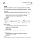
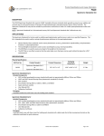
This operator's manual contains information and instructions for Spectronic Instruments
SPECTRONIC'J 20+and 20D+ spectrophotometersthat were believed accurate at the time this
manual was written. However, as part of Spectronic Instruments' on-going program of product
development, the specifications and operating instructions for these spectrophotometersmay be
modified or changed as needed.Spectronic Instrumentsreservesthe right to change suchoperating
instructions and specifications. Under no circumstances shall Spectronic Instrumentsbe obligated to
notify purchasers of any future changes in either this operator's manual or any other instructions or
specifications relating to the SPECTRONIC 20 series spectrophotometers,nor shall Spectronic
Instruments be liable in any way for its failure to notify purchasersof suchchanges.
FCC COMPLIANCE STATEMENT FOR U.S.A. USERS
This equipment generates,uses,and can radiate radio frequency energy,and if not installed and used
in accordance with the instruction manual, may cause interference to radio communications. It has
been testedand found to comply with the limits for Class A computing device pursuant to Subpart J of
Part 15 of FCC Rules, which are designed to provide reasonable protection against such interference
when operated in a commercial environment. Operation of this equipment in a residential area is
likely to cause interference in which casethe user at his own expense will be required to take
whatever measuresmay be required to correct the interference.
GENERAL SAFETY NOTES USED IN mlS MANUAL
This symbol alerts you to important infonnation about using the instt"Ument.Be sure to read and foIlow
the associatedinstt"UctionscarefuIly.
This symbol alerts you to potential electrical hazards. Be sure that only qualified persons perfonn the
related procedures.
This symbol alerts you to hot surfaces.Be sure to read and follow the associatedinstructions carefully.
Copyright @ 1997, Spectronic Instruments,Inc.
All rights reserved.
SPECTRONIC is a registered trademark of Spectronic Instruments,Inc.
All other brand and product names are trademarks or registered trademarks
of their respective companies.
NEW PRODUCT WARRANTY
Spectronic Instruments warrant~s the SPECTRONIC@20+ series of spectrophotometers against
defects in material and workmaAShipfor a period of three (3) years from the date of delivery.
Related accessoriesare warran~against defects in material and workmanship for a period of one
(1) year from the date of delivery.
This warranty covers all parts (except those specified below) and labor, and applies only to
equipment which has beeninstalled and operated in accordance with the operator's instruction
manual and which has beenserviced only by authorized Spectronic Instruments dealers or service
personnel. This warranty does not apply to equipment and accessoriesthat have beenmodified or
tampered with in any way, misused, or damaged by accident, neglect, or conditions beyond
Spectronic Instruments' control.
This warranty does not apply to lamps, glassware,and similar expendablecomponents. However,
such parts and components may be warranted by their manufacturer.
Spectronic Instruments is not responsible under this warranty for loss in operating perfonnance
due to environmental conditions.
THIS WARRANTY IS IN LIEU OF ALL WARRANTIES EXPRESSED, IMPLIED, OR
STATUTORY, INCLUDING, BUT NOT LIMITED TO, WARRANTIES OF FITNESS FOR A
PARTICULAR PURPOSE OR MERCHANTABILITY OR OTHERWISE, and states Spectronic
Instruments' entire and exclusive liability and the Customer's exclusive remedy for any claim in
connection with the sale or furnishing of services, goods, or parts, their design, suitability for use,
installation, or operations. Spectronic Instruments will in no event be liable for any direct,
indirect, special, or consequentialdamages,whatsoever, including loss of goodwill, whether
grounded in tort (including negligence), strict liability or contract, and Spectronic Instruments'
liability under no circumstances will exceed the contract price for the goods and/or services for
which liability is claimed.
II
Contents
Section
Operating
Environmental
1
-Introduction.
features
and
of
electrical
the
SPECTRONIC@
requirements
200+
20+
1-1
1-2
spectrophotometer.
spectrophotometer.
1-6
1-6
Section
Printing.
Sample
Technique
Setup/Installation
Remote
Environment
2
Measurements.
operation.-Installation
&
Operating
Procedures.
2-2
2-2
2-4
2-5
Section
Cleaning
Lamp
Replacement. 3
Wavelength
Service
Troubleshooting
Photometric
Replacing
-Maintenance.
the
Procedure
sample
phototubes
Calibration
linearity
compartment
check
.
Check.
3-1
3-1
3-2
3-2
3-3
3-4
3-6
3-6
Section 4 -Accessories.
AppendixA-ChoosingaReadoutMode..
Transmittance
Absorbance
Concentration
Concentration-Factor-Check
Appendix
2-12-12-1
Mode. Mode.
Mode.
B -Optical
A-1
A-1
A-1
A-1
A-2
Feature.
Diagram
III
!
~5:'
~et:
Section 1 -Introduction
summarizesthe specifications for the two current
models in the SPECTRONICBI20 series.
The SPECTRONI~ 20 seriesof spectrophotometers
is oneof the mostwidelyusedlaboratoryinstruments.
Overthe years,the serieshasbeenimprovedand now
includesthe SPECTRONI~ 20+andthe
SPECTRONIC@
200+.
Operational procedures for the SPECTRONICII 20 and
20D spectrophotometersare included in this manual.
This section describes these two latest instruments and
their basic operating features. The table below
Table 1-1 Specifications for SPECl'RONlCi> 20+ and SPECl'RONlCi> 20D+ Spectrophotometers
nONS
-SPECIFICA
SPECTRONIC"
SPECTRONIC' 20+
20nm
Specb'alslit width
340to 950nm
Wavelen~~
:t:2.5nm near 525nm
Wavelengthaccur~~y
Display
Photomenicrange
LED
%T, A, C, Factor,
Wavelenj!;th-
Meter
51/2"mirrored scale
linear %T, non-linear A
0 to 100%T
0 to 1.95A
0 to 1999C
(0.1 to 1000Factor)
0 to lOO%T
Oto2A
j:2%T
Photometricacc~~-
:to.5%T
Photometricnoise
Sb'ayr~iant energyAccessoryoutput
~owerreq~e_nts
Dimensions
-.
20D+
--O.5%T*
from 340nm to 95Onm
0 VDC nominal at lOO%T
1.0 VDC nominalat 100%T
RS-232Cseri&l!9port
OO/115.v.50/60Hz; 22Q/240V. 50/60Hz
W (41.3cm)x 8.5~21.6cm)
~g~t
* When measured with ap(X"opriateaccessoryfilter installed (Accessory Filter Kit 333129)
181bs.
(~g)
x 1?:5"D (34.3cm)
SPECTRONIC
Introduction
20'" series
Environmental and electrical requirements
Storage environment
The SPECTRONICII 20 series of spectrophotometers
has been designed to operate under the environmental
and electrical r'equirementslisted below.
-40°F to 140°F (-40°C to 60°C)
Relative humidity not to exceed 60%
Allow instrument to adjust to room temperature for 24
hours after taking it out of storage.
Line voltages
Altitude
Catalog #
Line voltage Frequency Current
333182-000
333182-002
333182-004
333182-005
115VAC
220VAC
240VAC
l00VAC
60 Hz
50/60Hz
50/60Hz
50/60Hz
333183-000
333183-002
333183-004
333183-005
115VAC
220V AC
240V AC
lOOVAC
60Hz
0.9 Amp
0.5 Amp
0.5 Amp
0.9 Amp
1.0 Amp
SO/60Hz 0.5 Amp
SO/60Hz 0.5 Amp
SO/60Hz 1.0 Amp
Operating environment
The instrument meetsthe specifications on the previous
page under the following conditions after a 30-minute
warm-up period.
Ambienttemperature
50°F
76°F
86°F
96°F
to 75°F (15°C to 24°C)
to 85°F (25°C to 29°C)
to 95°F (30°C to 35°C)
to 105°F (36°C to 40°C)
Relative humiditl'
20%
20%
20%
20%
to
to
to
to
80%
70%
60%
50%
Temperature should be maintained at :t4 of (:t2 °C).
Relative humidity should be maintained to :t5%.
"
Frombelowsealevelto 2000meters(6562feet)
For indoor use only
Installation CategoryII
Pollution Degree2
Your insb"umentpackage includes:
.SPECTRONICC8>20+(Cat. No. 333182) or
SPECTRONICC8>
200+ (Cat. No. 333183)
spectrophotometer
.SPECTRONIC'1 20+ Series Spectrophotometers
Operator's Manual (Cat. No. 333182-10001)
.Box of 12 test tube cuvettes (Cat. No. 331780)
.Oust cover (Cat. No. 332961-149)
.Y2" Adapter (Cat. No. 333178)
.1/16" Allen wrench (Cat. No. 332260-174) for
interchanging test-tube adapters
""6
//1
meter spectrophotometerwith a wavelength range of
340 nm to 950 nm. The nominal spectral slit width of
20 nm is constant over the entire range.
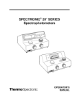
The SPECTRONICOII 20+ spectrophotometer (Cat.
Nos. 333182-000, 333182-02, 333182-04, 333182-05
or 333182-07), shown in Figure I-I, is a single-beam
2
3
I:.
-::-...
,.'
4
5
Figure I-I
SPECTRONIC 20+ spectrophotometer
KEY
1.
2.
3.
4.
5.
6.
Sample compartment
Pilot lamp
Wavelength control
Transmittance/Absorbance control (lOO%T/OA)
Power switch/Zero control
Filter lever
11
Introduction
SPECTRONIC 2or series
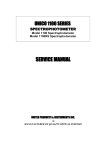
The SPECTRONIC" 20D+spectrophotometer(Cat.
Nos. 333183-000.33'3183-02.333183-04.333183-05
or 333183-07).shownin Figure 1-2.is a single-beam
digital specb"ophotometerwith a wavelength range of
340 nm to 950 nm. The nominal specb"alslit width of
20 nm is constant over the entire range.
5
3
2
6
7
4
~~-~---=-
9
81
1
9
10
Figure 1-2
$PECI'RONIC 20D+ spectrophotometer
KEY
I. Samplecompartment2.
Digital readout
3. Mode indicators4.
Mode selection
5. Decrease6.
Increase
7. Print
8. Wavelength control
9. Transmittance!Absorbance control (100% T lOA)10.
Power switch/Zero Control11.
Filter lever
,.
:~
The main features on the underside of the instrument
are shown in Figure 1-3.
g
g
<D-!
0
~
~'j
~~~
""I
~
d
Figure /-3
Bonomview ofSPECTRONIC20+or 20V+
KEY
1. Lampaccessdoor with thumbscrew2.
Filter lever3.
Analogoutputjack/SerialI/O port4.
line voltageswitch(underthis plate)[internationalmodelsonly]
Operating
features
of the SPECTRONIC~
20+
readout and readjust if necessary.
spectrophotometer
The main controls for routine operation are the Power
Switch{Ze;roControl. Wavelength Control. Filter Lever
and Transmittance/AbsorbanceControl.
Power Switch / Zero Control
The ON-OFF main power switch is operatedby the
Power SwitchfZero Control knob. The Zero Control
knob is used to set the display to a O%T readout when
the sample compartment is empty and the adapter cover
is closed.
.8!!gjQg OutQut Jack
This jack is used to connect an analog recorder to the
instrument (see Figure 1-3). The analog output signal
level is fixed at approximately I VDC at lOO%T. This
output is not adjustable.
The signalsoneachpin are listedbelow:
1 Analogoutput
2 Analogground
3 Analogground
4 Meter (+)
5 Analog output
6 Meter (-)
Wavelength Control
The Wavelength Control selectsthe desired analytical
wavelength of the instrument. The selectedwavelength
is indicated on the wavelength scale in the window next
to the knob. Red numbers indicate that the 600-950nm
filter should be used; black numbers indicate that the
340-599nm filter should be used. All gradations are in
5-nm intervals.
The main controls for routine operation are the Power
SwitchfZero Control, Wavelength Control, Filter Lever,
Transmittance/Absorbance Control, the MODE
selector and Factor Adjust controls.
Filter Lever
The accessoryAnalog Output/Serial I/O port is located
on the underside of the instrument, as shown in Figure
Operating
features
of the SPECTRONIC~
20D+
spectrophotometer
1-3.
This control selectsthe filter to be used for the
measurement:
.Red is used for measurementsfrom 600 to 950nm.
.Black is used for measurementsfrom 340 to 599nm.
Power Switch / Zero Control
~
The ON-OFF main power switch is operatedby the
Power SwitchfZero Control knob. The Zero Control
knob is used to set the display to a O%T readout when
the sample compartment is empty and the adapter cover
is closed.
Readings are taken directly from the meter in either
transmittance or absorbance.
Transmittance / Absorbance Control
This control setsthe display to lOO%T (O.OA)when a
cuvette containing a blank reference solution is inserted
in the sample compartment. It must be reset
whenever the analytical wavelength has been
changed. When operating at a fixed wavelength for an
extended period of time, check the 100%T (O.OA)
Wavelength Control
Factor Adjust Controls
The Wavelength Control selectsthe desired analytical
wavelength of the instrument. The selectedwavelength
appears on the left side ofdte lED display. The Filter
Lever should be set to the proper filter for the
The pushbuttons labelled INCREASE and
DECREASE are used in the CONCENTRATION and
FACTOR modes. To set a lower CONCENTRATION
or FACTOR value, press and hold down the
DECREASE button until the desired value is displayed.
To set a higher value, press and hold down the
INCREASE button until the desired value is displayed.
wavelength setting.
Filter Lever
This conb"ol selectsthe filter to be used for the
measurement:
.Red is used for measurementsfrom 600 to 950nm.
.Black is used for measurementsfrom 340 to 599nm.
P.ri.o1
Diaital Readout
Analoa Cutout / Seriall/C
The Digital Readout displays wavelength and data
readings. The four LED status indicators, next to the
labels TRANSMnT ANCE, ABSORBANCE,
CONCENTRATION and FACTOR indicate the
MODE currently active.
Analog Output
This pushbutton is used to send data to a serial printer
connectedto the output jack.
Port
This port is used to connect an analog recorder to the
instrument. The analog output signal level is
approximately I VDC at IOO%T. This output is not
adjustable.
Transmittance / Absorbance Control
Serial Port
This control setsthe display to lOO%T (O.OA)when a
cuvette containing a blank reference solution is inserted
in the sample compartment. It must be reset
whenever the analytical wavelength has been
changed. When operating at a fixed wavelength for an
extendedperiod of time, check the lOO%T (O.OA)
readout and readjust if necessary.
MODE Select
This controlselectstheTRANSMITf ANCE,
ABSORBANCE,CONCENTRAllON or FACTOR
mode.
The Serial Input/Output (I/O) Port is used to connect
the instrument to the Accessory Printer (Cat. No.
335488) or to an external device, enabling the
instrument to acceptand executeanyone of six
commands sent from the device in RS-232-C format.
The signals on each pin are listed below:
1 Analog output
2 Clear to send (CTS)
3
Ground
4
5
6
Transmit data (TXD)
Receive data (RXD)
Print
Refer to page 2-5 for remote operation and to Table
2-1 on page 2-1 for cabling requirements.
Section
3 -Maintenance
Becauseof the functional design and reliability of the
SPECTRONICCIJ
20+ and 20D+ spectrophotometers.
routine customer maintenancehas been reduced to
replacementof the 6.0-volt, 3.00-amperes source lamp
(Cat. No. 333385). SPECTRONIC'J 20 and 20D
models also require replacementof the phototube (see
Table 2-2).
1
°-
.-J
I
5
I
3
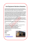
Note: The sourcelamphasa nominallife of 250
hours.
The operatormayalsoperformroutinechecksfor
wavelengthcalibrationandphotometricaccuracy.
Figure3-1
Lamp replacement
KEY
1. Lamp
2. Lamp socket
3. Mounting bracket
Lamp Replacement
4. Lamp flange
5. Locating pins
6. Terminals
6. Install a new lamp by properly aligning the large
openings in the lamp flange with the locating pins.
Press the lamp and the lamp socket toward each
other and rotate the lamp clockwise until secure.
~
I. Turn off and unplug the instrument.
2. Tilt up the unit and seton its back.
3. Loosenthe thumbscrewonthe lampaccessdoorand
openthe door(seeFigure 1-3).4.
Using finger pressure,pressthe lamp sockettoward
the mountingbracket(Figure3-1).
/'/"
.-I".
~
7.
Do nottouchthelampwithyourfingers!
Clean the lamp of fingerprints and oils, close the
door and tighten securely. This is essential for
proper operation.
Note:
&
Do nottouchthelampwithyourfingers!
5. To avoid getting skin oils on the surface of the lamp,
use the Lamp Gripper supplied with the instrument
to grip the lamp. Push the lamp toward the lamp
socket and rotate counterclockwise to remove it.
.Do not push on the lamp sockettenninals. This will
inhibit the installation of a new lamp.
Cleaning the sample compartment
~
In the event a test tube breaks in the sample
compartment, it is important to remove the glass and
any spilled liquid as soon as possible.
@-i
~
1. Turn off and uplug the instrument.2.
Use protective equipment (safety goggles, gloves,
lab coat, etc.).
3. Using tweezers,remove broken pieces of glass from
the sample compartment.4.
While supporting the instrument, move it to the edge
of the lab bench so that the lamp accessdoor may be
~
opened.
5. Loosenthe lamp accessdoor thumbscrew and
carefully open the door. Spilled fluid may be present
inside. Make sure to clean up all liquid that was
Figure 3-2
KEY
1. Photodiode
2. Connectionwire
spilled.6.
Reachinside the lamp compartment and remove any
remaining glass.
7. Tip the instrument back on the lab bench and clean
the sample compartment with an appropriate
cleaning solvent.
8. Visually inspect the lamp, photodiode or phototube,
and filters to determine if any liquid has spilled on
them. Refer to Figure 3-2 or Figure 3-3.
9. Remove any liquid spilled on the lamp, filter,
photodiode or phototube surfaces:
.Lamp, filter and phototube surfaces: Clean
with a soft cloth or the softestarea of a cotton
swab and glass cleaner
.Photodiode:
The photodiode is easily
damaged;cleaning should be performed by your
Spectronic Instruments service organization.
Clean the photodiode only if liquid is spilled on
it. Use very light pressure with the softest
area of a cotton swab dipped in high-grade
isopropyl alcohol. Do not touch the wire
connected to the detector.
~
.kJ...ll
vAI.
10.
Location ofphotodiode
3. Lamp
4. Filter
Close the door and tighten the thumbscrew.
11. Check the calibration of the insuument using the
procedures below or call your local Spectronic
Insuuments service organization, if necessary.
Wavelength Calibration Check
Under nonnal operating conditions, the
SPECTRONI~ 20+and 20D+ spectrophotometers
should retain their wavelength accuracyindefinitely. If
the instrument is subjectedto a severe shock or other
abuse,wavelength performance may be checked by one
of three methods:
.Cobalt solution check
.Didymium filter from the Accessory Filter Kit (Cat.
No. 333129)
.Wavelength Accuracy Test from SPECTRONIC'I
Standards(Cat. No. 333150)
An explanation of the cobalt solution check follows.
Instructions on use of the didymium filter and
SPECTRONIC!>Standardsare found in the user's
manual for each accessory.
3-2
Cobalt solution check
Photometric linearity check
To prepare a stock cobalt solution:
I. In a I-liter volumetric flask, place 200 mL distilled
water. Slowly and cautiously add 10 mL
concentratedhydrochloric acid (ACS grade). Mix
and make to volume with distilled water to obtain
I % hydrochloric acid solution.
2. In a I-liter volumetric flask, place 22 to 23 gm
cobalt chloride (CoC~, ACS grade). Dissolve in the
I % hydrochloric acid. Make to volume with 1%
hydrochloric acid to obtain cobalt chloride stock
solution.
If the photometric linearity of the instrument is
questionable, first check your analytical procedure and
technique (see Techniques on page2-2). Ifproper
operation is still in doubt, use the Photometric
Accuracy/linearity Test from SPECTRONIC8'
Standards(Cat. No. 333150) to test and evaluate
photometric performance of your instrument.
To perform the cobalt solution check:
I. Turn on the Power Switch/Zero Control and allow
the instrument to warm up for at least 15 minutes.
2. If you have a SPECTRONIC" 20D or 20D+, set the
display mode to Transmittance.
3. With the sample compartment empty and the cover
closed, adjust the Power Switch/Zero Control until
the meter or display readsO%T.
4. Setthe Wavelength Control to 500 nm.
5. Setthe Filter Lever to 340 -599nm.
6. Insert the glassware filled with distilled water into
the sample compartment and use the
Transmittance!Absorbance Control to setthe meter
or display to lOO%T.
7. Replace the distilled water with the cobalt chloride
solution.
8. Insert the glassware filled with the cobalt chloride
solution into the sample compartment.
9. Read %T on the meter or display.
10. Repeatsteps 4 through 9 at 505,510,515 and
520 nm. The instrument is in proper calibration
when minimum transmittance (maximum
absorbance)occurs between 505 and 515 nm. The
specific transmittance (or absorbance)values are
unimportant.
Wavelength calibration adjustment
If the wavelength accuracyis out of tolerance, refer to
the Service Procedure section on page 3-5. Customer
recalibration is not recommended.
The alternatemethodbelowusesspeciallyprepared
potassiumdichromatesolutions.
I. Turn on the Power Switch/Zero Control and allow
the instrument to warm up for at least 15 minutes.
2. Make sure that the sample compartment is empty
and the cover is closed, then adjust the Power
Switch/Zero Control until the display readsO%T.
3. If you have a SPECTRONICII200 or 200+, set the
display mode to Absorbance.
4. Prepare O.OIN sulfuric acid diluent by adding 0.3mL
of concentratedsulfuric acid to about 500mL of
deionized or distilled water in a clean I L volumetric
flask. Fill to volume with deionized or distilled
water.
5. Prepare a stock solution of potassium dichromate by
weighing 0.500g of potassium dichromate (e.g.,
Fisher Certified A.C.S. potassium dichromate,
formula weight 294.19) and dissolving it in about
400mL ofO.OIN sulfuric acid solution in a 500mL
volumetric flask. Fill to volume with O.OIN sulfuric
acid solution. This is your stock 1.0g/L potassium
dichromate solution.
6. Measure 2.5mL of the stock 1.0g/L potassium
dichromate solution into a clean lOOmL volumetric
flask containing about 75mL O.OIN sulfuric acid
solution. Fill to volume with O.OIN sulfuric acid
solution. This is your 0.025g/L potassium
dichromate solution.
7. Measure 5.0mL of the stock 1.0g/L potassium
dichromate solution into a clean lOOmL volumetric
flask containing about 75mL O.OIN sulfuric acid
solution. Fill to volume with O.OIN sulfuric acid
solution. This is your 0.05g/L potassium dichromate
solution.
8. Set the Wavelength Control to 350nm.
9. Set Filter Lever to 340 -950nm.
SPECTRONIC 2ar series
Fill a IOmrn pathlength rectangular cuvette with
O.OIN sulfuric acid solution and place it in the
sample compartment.11.
Set the:readout of the instrument to OA.12.
Fill the IOmm pathlength rectangular cuvette with
O.O25g/Lpotassiumdichromate solution, place it
in the sample compartment and read the
absorbance. You should expect to read O.248A.13.
Fill the IOmm pathlength rectangular cuvette with
O.O5g/Lpotassium dichromate solution, place it in
the sample compartment and read the absorbance.
You should expect to read O.496A.
Note: Values should be within O.O2Aof the
expectedabsorbance values, if the solutions
have beenprepared carefully.
Replacing phototubes (SPECTRONIC~ 20 or20D
models only)
4
~
The lamp and surrounding metal parts get
very hot during operation. Before
removingthe phototube,turnoff the instrument
and allowthe areato cool downfor 10minutes.
10.
To changethephototube:
1. Turn ofTand unplug the instrument.
2. Tilt up the unit and seton its back.
3. Loosenthe thumbscrewonthe lampaccessdoor
(seeFigure1-3).
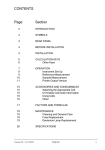
4. Removethe phototubeusingthe plasticstrapsas an
aid (seeFigure3-3).
~
Do nottouchthelampwithyourfingers!
5. Install the new phototube. If a filter is required,
insert it into the holder on the inside of the door (see
Figure 3-3). The tube and filter must be clean and
free of fingerprints, (If necessary,use a lint-free
tissue for cleaning.)
6. Close the door and securely fastenthe thumbscrew.
This is essentialfor proper operation.
~
~
SPECTRONIC 2or series
Maintenance
g
I~
~
r<..
~
~
0
'-,
"'"
'-..J~
~
1'\)
/
Figure 3-3
Lamp compartment for SPECTRON/('i> 20 and 20D models
KEY
I. Phototube
2. Plastic straps
3. Filter holder
4. Lamp
Service Procedure
If the instrument develops a malfunction that cannot be
corrected by operator maintenance,it may be serviced
by your local Spectronic Instruments service
organization.
.If you are in the U.S.A., contact Spectronic
Instruments whether the instrument is still under
warranty or it has expired.
.If you are outside the U.S.A., contact the distributor
from whom you purchasedthe instrument whether
the instrument is still under warranty or it has
2. Include a detailed letter inside the shipping carton,
fastened to the instrument,describing the trouble.
Pleaseinclude the name and phone numberof the
person or departmenthead most familiar with the
problem. This information enablesservice personnel
to make required repairs promptly and at least
expense.
3. In the United States,mark on the shipping container:
FIRSTClASS LElTER ENCLOSED
First class postage is required only on the letter. The
carton is acceptedat standard mail rates.
expired.
If it is necessaryto ship the instrument:
I. Wrap the spectrophotometerin plastic, then pack
carefully in a crush-resistant carton with at least
three inches of shock absorbing material to prevent
trapsit damage.
Troubleshooting
Table 3-1, Operator's Troubleshooting Guide, outlines
some diagnostic techniques that may help you isolate
the causeof a problem.
Table3-1 Operator'stroubleshootingguide
I
Problem
II.
12.
Instru~nt doesnot function a. Power line cocd nol connected to outlet.
-'
Refer to service manual oc servicecenter.
Internal fuse blown.
d. Defectiveelectronicco
nent.
cover nol closed.
wer outlet.
Refer to service manual oc servicecenter.
CI
I b. Lamp accessdOCX'
nol tightly closed.
CI
..:. Pholotubedefective.
Re
ten thumbscrew.
d. Defective electronic component.
Refer to service manual oc servicecenter.
ii. POCX'
sampling technique.
.Eliminate
bubbles oc particles in solution.
.Set IOO%Tona
'ate blank solution.
o. Filter selection lever is in wrong IXJsition.
Set filter I v
incaTect.
,~~
.cocd.
T
Meter/Display doos not zero. !~a. Sample co~ment
3. Readings are drifting <r
P'
D. Dead ~wer outlet.
ow. Fu~s
from sample.
ReOK)vesa
d. Excessive line voltage variation.
Wrong line voltage setting (international models'
only).
.Source
lamp defective.
sis.
; Checkvoltageandgrounding.
Reset Line Voltage Selection Switch.
Replace with new lamp.
g. Phototubedefective.
n. Defective electronic co
sition.
Replace as required.
nent.
Refer to service manual or service center
I
Th~l~!~ued)
.,.
~Iter
1.
~.
h.
-
Problem
PossibleCause
4. Cannot set IOO%T (O.OA),
fK display flashes.
~v-
lOO%T not lX"operlyset.
:)et lOO%T with blank solution in the sample
compartnx:nt and cover closed. Several turns or the
J
Filter selection lever in wron
ition.::.
O%T not (X"operlyset (alllIKxlels except
SPECTRONIce 200').
lOO%Tcontrol~y~~,
leverto~~~
:5et O%T with the sample compartment empty and the
Occluderclosed.
coverclosed.
rnstalltesttubein sarnp~~rnent.
SanIDleholdernot fully insertedintoadapter.
Insertfu!Iy.
Source lamp weak IX' burned out.
Replace with new lamp.
Wrong line voltagesetting(internationalmodels~)').
i.
5. Readingsarenot reJx:atable
eventhoughtheO%Tand
100%T readingsare set
cmectly.
Phototube
weak.
Replaceasrequired.
Erroc in wavelength calibration.j.
Checkcalibration.
Defective electronic component.k.
Refer to service manual (X' service center.
InCOlTectphototube oc filter installed.
CheckTable2-2 (page2-2) roccocrectphototube
(SPECTRONIce20nOD only) andfilter, andinstall.
Looselamp.
Tighten thumbscrew on lamp accessdOCX".
Ti~htensetscrewinsideadapter.
.Loose sample holder adapter.
Prx:r analytical technique.
Clean oc replace dirty test tubes; renK>vebubbles, etc.
:)ee Techni ues on
e 2-2.
Test tubepositionnotr~ting.
Always position fiducial line in exactly the sameplace
when test tube is inserted into adajXer. Use square
cuvettes.
-
Meter sticking (SPECTRONIC8 20 and 20+ only)
Tap lightly foc~sible cocrection.If IToblempersists,
referto servicecenter.
3-7
Section 4 -Accessories
Table 4-1 Accessories available for SPECTRONIC'" 20 and 20+ series ofspectrophotometers
Accessorv
Catalol! Number
Descrintion
Cell Holders and Sample
SeeTable 4-2 on page4-2.
Compartment Adapters
SPECTRONIC«IStandards
333150
Quick, reliable way to test and evaluate instrument
performance: O%T, wavelength accuracy, stray radiant
energy, photometric accuracy; requires Cuvette Holder,
Cat. No. 333176, and Adapter, Cat. No. 333178 (included
with instrument)
Accessory Filter Kit
333129
Use for lowering stray light to ~O.5%T and for validating \
wavelength accuracy; includes four stray radiant energy I
2ndorder filters and one didymium filter
AccessoryPrinter
335488
RS-232-CSerialInterfaceCable
333177
VernierSoftware
RS-232CCable
333192-02
333132
ConnectsSPECTRONIC~200 to AccessoryPrinteror
computer
For using the SPECTRONIC~ 20D or 20D+ with an
IBM-compatible computer; includes standard curve,
wavelength scan and kinetics programs; see Table 2-1 on
page 2-1 for required cable
Cable Kit to connect SPECTRONIC 200 or 200+ to an
IBM-compatible computer, or SPECTRONIC 200+ to
335488 40-column printer
SPECTRONI~ 20+Series
ServiceManual
333182-10020
Includesopticaldiagrams.circuit diagrams.diagnostics,
troubleshooting,schematicsand assemblies
SPECTRONIC»>20 Series
Service Manual
333175-10020
For SPECTRONIC(!)20 and 20D models; includes optical
diagrams, circuit diagrams, diagnostics, troubleshooting,
schematics and assemblies
EducationalManual
332909-10030
Bookletof lab experimentsandbasic spectrophotometry
information
4-1
~
Glassware selection and samgling ogtions
To change adapters,loosen the small set screw on the
inner wall of the adapter using the adapterwrench
clipped to the bottom of the instrument (see Figure
1-3).
In addition to the standard Y2" test tube and Y2" adapter
supplied with the instrument, several types of
glassware are available. The sample adapter must
match the glassware, as shown in the chart below.
Table4-2 Cell selectionchartfor SPECTRON/("iI20.seriesofspectrophotometers
PICTURE
DESCRIPTION
Square Cuvette
ro
PATHLENGTH
CATALOG
NUMBER
331709
I
10mm
Optical Glass
45mm tall
333178
(included with
ALSO
REQUIRES:
333176
Cell Holder
_instrumeB!)-
Cuvette
Optical Glass
100 mm tall
331701
Semi-Micro
331713
Cuvette
ADAPTER
11.66 mm
333178
(included with
instrument)
10mm
333178
(included with
instrument)
333176
Cell Holder
(included with
331713
cuvettes)
1/2' Test Tube
Optical Glass
100 mm tall
331780
3/4' Test Tube
Optical Glass
150 mm tall
331781
l' Test Tube
Optical Glass
150 mm tall
331782
0.459'
(11.7 mm)
333178
(included with
instrument)
0.657'
(16.69 mm)
332931
0.880'
332930
(22.4 mm)
332932
Light Shield
332932
Light Shield
I
I
SPECTRONIC 2or series
Accessories
The design of the standard adapterprovided with the
insb"Umentwas changed in 1986. The current adapter(Cat.
No. 333178) accommodatesa 1/2"diameter test tube or a 1/2"
square cuvette. Prior to 1986,the standard adapter(Cat.
No. 333127) accommodated only the 1f2"diameter test tube.
To identify the standard adaptereasily, turn the adapter
bottom end up and look into the barrel of the adapter.
Figure 4-1 illustrates the pre-1986 design which will not
accommodatea Y2"squarecuvette. This can be replaced with a
current adapter(Cat. No. 333178) to accommodateY2"square
cuvettes.
Figure4-1 Standardadapter
KEY
I. Spring found in pre-1986 adapters
3
Appendix.A
Transmittance
-Choosing
Mode
All SPECTRONICISI20+ series spectrophotometers
measurethe relative amount of light transmitted,
yielding results in transmittance. The transmittance
mode is useful for calibration, stray radiant energy
tests and filter studies. Furthermore, very low
concentrations may be measured with greater
sensitivity in the transmittance mode. When the
transmittance mode is used,the reagent blank sets
lOO%T, and the results for standard solutions and
unknown samples are obtained as percent
transmittance.
A standard curve may be constructed on
semi-logarithmic paper by plotting the percent
transmittance on the logarithmic axis vs. the
concentration of known standard solutions on the
linear axis. The best line is drawn through these
points. The concentration of unknown samples may
then be determined by locating the concentration
value which corresponds to the percent transmittance
of the unknown on the standard curves.
a Readout Mode
To eliminate %T to A calculations, each model of the
insb"umentprovides conversion of transmittance to
absorbance:
.The SPECTRONIC~ 20+ has an absorbancescale
marked with values corresponding to percent
transmittance. The operator may simply read the
absorbancescale and use these values to consb"ucta
standardcurve as described above.
.The SPECTRONIC~ 200+ offers precise electronic
conversion of transmittance to absorbance.When
the absorbancemode is used,the reference blank
sets O.OOOA,
and the results for standards and
unknowns are obtained in absorbance. Results in
absorbance may be related to concentration by
Beer's Law, A=abc, if the absorptivity and
pathlength are known, or by consb"uctionsof a
standardcurve as described above.
Absorbancemeasurements
are usefulfor kinetics
studiesand for reactionsystemswhichdo not obey
Beer'sLaw andthereforehavenon-linearstandard
plots.
Concentration Mode
Absorbance
Mode
Usually, the operator desires results in absorbance for
direct correlation of concentration by Beer's Law:
A=abc. Results in percent transmittance may be
converted to absorbance values by use of
transmittance-absorbance conversion tables or by the
formula A=-log,o T. Results in absorbance may be
plotted against the concentration of known standards
on rectilinear graph paper. The best line is drawn
through these points to construct a standard curve.
The concentration of unknowns may then be
detennined by locating on the standard curve the
concentration value which corresponds to the
absorbanceof the unknown.
The SPECTRONICIII 20D+provides a more
convenient readout, the concentration mode, which
eliminates the necessity for constructing a standardcurv
The instrument electronically converts results
in absorbanceto concentration units by multiplying
the absorbancevalue by the factor which is the inverse
of the slope of the standard curve (factor = l/ab).
Note that the concentration mode can be used only if
the linearity of the standard curve has been verified
for the test conditions used. These test conditions
include wavelength, concentration range of interest,
cuvette pathlength and analytical procedure.
Furthermore, the concentration mode may be used
only if the standard curve has a positive slope (i.e.,
absorbanceincreases with concentration).
When using entered standard solutions, the l/ab factor
is used to convert absorbanceto concentration,
according to the equation
C=f*A
ConcentrationMeasurements
usingFACTORmode
on page2-4 describeshow to usethe factormode.For
more informationon concentrationmeasurements
and
othertechniques,contactSpectronicInstruments'
ApplicationLaboratoryand requesta list of available
SpecTechNotes.
Note: It is not actually necessaryto know the l/ab
factor becausethis factor is introduced into the
instrument when the concentration adjust
control is used to set the digital display to read
the concentration of the standard. See page 2-4
for detailed instructions.
Concentration-Factor-CheckFeature
To verify that operating conditions do not vary
between reagent batches or from day to day, use the
concentration-factor-check features as follows: After
the concentration mode has been set up with standard
solutions, press the MODE select control until the
FACTOR LED lights, and read and record the factor
given on the digital display. Every time new standard
solutions are used for the same test (such as for a new
reagent batch or when setting up the instrument),
press the MODE select control until the FACTOR
LED lights, and note the factor on the digital display.
A change in the factor indicates a change in the slope
of the standard curve due to variation in operating
conditions. It is recommended that a standard always
be used to set the concentration mode. The operator
may choose, however, to set the blank to OOOA,then
switch to the concentration mode.
C)
E
cu
...
cu
.-
c
"i
u
;
Q,
0
I
m
><
."C
G)
C
Q,
Q,
c(
a.
~
:s
z
w
..cn
~
Z
:J
..-
~
cn
w
c..>
z
~
z
w
I
I
I
I
cn
z
W
..J
I
,
I
I
I
z
cn
W
-J
I
I
I
I
(/)
z
W
-J
.[!
t:
IZ
W
a.~
o~
1-:)
00...,
..J<
wO
ml-
-0'
< 0
a:o
>-r-
<0
~
~
E
,§-
~
~
cn
£11
t~
~
~
~
b
~
"t:
zcn
't>
Ww
W
~
-
LL
-
~
0
~
t.; ~
8"-=:
~
E
~
0
~
u
~
~
...
~
U,,-cn
wI-
ct::)
0
w u.w
x
~
a:
t:
-J
ffi
'f~
I!\
I
I
I
I
I
I I
II,
~
I
I
I
n
W
tW
Q
0
~
~
~
0
~
I
D..
nstruments
A subsidiary of Thermo Optek, a Thermo Instrument Systems company.
SPECTRONIC INSTRUMENTS, INC.
820 linden Avenue, Rochester, NY 14625, USA
Telephone: (800) 654-9955 or (716) 248-4000, Facsimile: (716) 248-4014,
E-Mail: [email protected], Web Site: http://www.spectronic.com
SPECTRONIC INSTRUMENTS, INC. (EUROPE)
93/96 Chadwick Road, Astmoor Industrial Estate, Runcorn, Cheshire W A7 1PR, England
Telephone: Int + 44-1928-562522, Facsimile: Int + 44-1928-562529
THERMO CHINA
3-5B Asia Games Garden, No. 12 Xiaoying Dong Lu, Chaoyang District, Beijing (100101), China
Telephone: Int + 8610-64974945, Facsimile: Int + 8610-64974946
For Asia Pacific and Latin America sales offices, contact Rochester, New York, USA.
333182-10001,
Rev. I .7/98
Printed in the U.S.A.