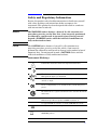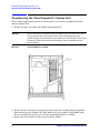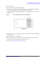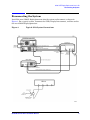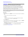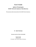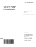
1
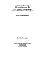
Agilent Technologies
85103G Service Kit
CRT Display Replacement
for the 8510C Network Analyzer
Installation Manual
Manufacturing Part Number: 85103-90015
Printed in USA
November 2002
Supersedes: August 2001
Notice
The information contained in this document is subject to change
without notice.
Agilent Technologies makes no warranty of any kind with regard to this
material, including, but not limited to, the implied warranties of
merchantability and fitness for a particular purpose. Agilent
Technologies shall not be liable for errors contained herein or for
incidental or consequential damages in connection with the furnishing,
performance, or use of this material.
Agilent Technologies assumes no responsibility for the use or reliability
of its software on equipment that is not furnished by Agilent
Technologies.
This document contains proprietary information which is protected by
copyright. All rights are reserved. No part of this document may be
photocopied, reproduced, or translated to another language without
prior written consent of Agilent Technologies.
Restricted Rights Legend
Use, duplication, or disclosure by the U.S. Government is subject to
restrictions as set forth in subparagraph (c)(1)(ii) of the Rights in
Technical Data and Computer Software clause at DFARS 252.227-7013
for DOD agencies, and subparagraphs (c)(1) and (c)(2) of the
Commercial Computer Software Restricted Rights clause at FAR
52.227-19 for other agencies.
Agilent Technologies
1400 Fountaingrove Parkway
Santa Rosa, CA 95403-1799, U.S.A.
© Copyright Agilent Technologies 2001, 2002
ii
Certification
Agilent Technologies certifies that this product met it’s published
specifications at the time of shipment from the factory. Agilent
Technologies further certifies that its calibration measurements are
traceable to the United States National Institute of Standards and
Technology (NIST, formerly NBS) to the extent allowed by the Institute’s
calibration facility, and to the calibration facilities of other
International Standards Organization members.
Warranty
THE MATERIAL CONTAINED IN THIS DOCUMENT IS PROVIDED
"AS IS," AND IS SUBJECT TO BEING CHANGED, WITHOUT
NOTICE, IN FUTURE EDITIONS. FURTHER, TO THE MAXIMUM
EXTENT PERMITTED BY APPLICABLE LAW, AGILENT
DISCLAIMS ALL WARRANTIES, EITHER EXPRESS OR IMPLIED
WITH REGARD TO THIS MANUAL AND ANY INFORMATION
CONTAINED HEREIN, INCLUDING BUT NOT LIMITED TO THE
IMPLIED WARRANTIES OF MERCHANTABILITY AND FITNESS
FOR A PARTICULAR PURPOSE. AGILENT SHALL NOT BE LIABLE
FOR ERRORS OR FOR INCIDENTAL OR CONSEQUENTIAL
DAMAGES IN CONNECTION WITH THE FURNISHING, USE, OR
PERFORMANCE OF THIS DOCUMENT OR ANY INFORMATION
CONTAINED HEREIN. SHOULD AGILENT AND THE USER HAVE
A SEPARATE WRITTEN AGREEMENT WITH WARRANTY TERMS
COVERING THE MATERIAL IN THIS DOCUMENT THAT
CONFLICT WITH THESE TERMS, THE WARRANTY TERMS IN
THE SEPARATE AGREEMENT WILL CONTROL.
Assistance
Product maintenance agreements and other customer assistance
agreements are available for Agilent Technologies products.
For assistance, refer to “Contacting Agilent” on page iv.
iii
Contacting Agilent
Any adjustment, maintenance, or repair of this product must be
performed by qualified personnel. Contact Agilent for assistance.
Online assistance: www.agilent.com/find/assist
United States
(tel) 1 800 452 4844, or
1 800 593 6635 for on-site
service of systems
Latin America
(tel) (305) 269 7500
(fax) (305) 269 7599
Canada
(tel) 1 877 894 4414
(fax) (905) 282-6495
Europe
(tel) (+31) 20 547 2323
(fax) (+31) 20 547 2390
New Zealand
(tel) 0 800 738 378
(fax) (+64) 4 495 8950
Japan
(tel) (+81) 426 56 7832
(fax) (+81) 426 56 7840
Australia
(tel) 1 800 629 485
(fax) (+61) 3 9210 5947
Singapore
(tel) 1 800 375 8100
(fax) (65) 836 0252
Malaysia
(tel) 1 800 828 848
(fax) 1 800 801 664
Philippines
(tel) (632) 8426802
(tel) (PLDT subscriber only):
1 800 16510170
(fax) (632) 8426809
(fax) (PLDT subscriber only):
1 800 16510288
Thailand
(tel) outside Bangkok:
(088) 226 008
(tel) within Bangkok:
(662) 661 3999
(fax) (66) 1 661 3714
Hong Kong
(tel) 800 930 871
(fax) (852) 2506 9233
Taiwan
(tel) 0800-047-866
(fax) (886) 2 25456723
People’s Republic of
China
(tel) (preferred):
800-810-0189
(tel) (alternate):
10800-650-0021
(fax) 10800-650-0121
India
(tel) 1-600-11-2929
(fax) 000-800-650-1101
iv
Safety and Regulatory Information
Review this product and related documentation to familiarize yourself
with safety markings and instructions before you operate the
instrument. This product has been designed and tested in accordance
with international standards.
WARNING
The WARNING notice denotes a hazard. It calls attention to a
procedure, practice, or the like, that, if not correctly performed
or adhered to, could result in personal injury. Do not proceed
beyond a WARNING notice until the indicated conditions are
fully understood and met.
CAUTION
The CAUTION notice denotes a hazard. It calls attention to an
operating procedure, practice, or the like, which, if not correctly
performed or adhered to, could result in damage to the product or loss of
important data. Do not proceed beyond a CAUTION notice until the
indicated conditions are fully understood and met.
Instrument Markings
When you see this symbol on your instrument, you should refer to the
instrument’s instruction manual for important information.
This symbol indicates hazardous voltages.
The C-tick mark is a registered trademark of the Spectrum
Management Agency of Australia.
This symbol indicates that the instrument requires alternating
current (ac) input.
The CE mark is a registered trademark of the European Community.
If it is accompanied by a year, it indicates the year the design was
proven.
The CSA mark is a registered trademark of the Canadian Standards
Association.
1SM1-A
ICES/NMB-001
This text indicates that the instrumentis an Industrial Scientific and
Medical Group 1 Class A product (CISPER 11, Clause 4).
This ISM device complies with Canadian ICES-001.
Cet appareil ISM est conforme a la norme NMB-001 du Canada.
This symbol indicates that the power line switch is ON.
This symbol indicates that the power line switch is OFF or in
STANDBY position.
v
Safety Earth Ground
This is a Safety Class I product (provided with a protective earthing
terminal). An uninterruptible safety earth ground must be provided
from the main power source to the product input wiring terminals,
power cord, or supplied power cord set. Whenever it is likely that the
protection has been impaired, the product must be made inoperative
and secured against any unintended operation.
Before Applying Power
Verify that the product is configured to match the available main power
source as described in the input power configuration instructions in this
manual. If this product is to be powered by autotransformer, make sure
the common terminal is connected to the neutral (grounded) side of the
ac power supply.
Battery Information
The 8510C uses a lithium polycarbon monoflouride battery to power the
instrument clock. The battery is located on the A7 I/O board of the
85101C display/processor. This battery is not field replaceable. Replace
the A7 I/O board if the battery requires replacement.
WARNING
Danger of explosion if battery is incorrectly replaced. Replace
only with the same or equivalent type recommended. Discard
used batteries according to manufacturer’s instructions.
vi
Typeface Conventions
Italics
• Used to emphasize important information:
Use this software only with the Agilent Technologies xxxxxX system.
• Used for the title of a publication:
Refer to the Agilent Technologies xxxxxX System-Level User’s Guide.
• Used to indicate a variable:
Type LOAD BIN filename.
Instrument
Display
• Used to show on-screen prompts and messages that you will see on
the display of an instrument:
The Agilent Technologies xxxxxX will display the message
CAL1 SAVED.
Keycap
• Used for labeled keys on the front panel of an instrument or on a
computer keyboard:
Press Return.
[Softkey]
• Used for simulated keys that appear on an instrument display:
Press [Prior Menu].
User Entry
• Used to indicate text that you will enter using the computer
keyboard; text shown in this typeface must be typed exactly as
printed:
Type LOAD PARMFILE
• Used for examples of programming code:
#endif//ifndef NO_CLASS
Path name
• Used for a subdirectory name or file path:
Edit the file usr/local/bin/sample.txt
Computer Display
• Used to show messages, prompts, and window labels that appear on
a computer monitor:
The Edit Parameters window will appear on the screen.
• Used for menus, lists, dialog boxes, and button boxes on a computer
monitor from which you make selections using the mouse or
keyboard:
Double-click EXIT to quit the program.
vii
viii
8510C CRT Display Replacement
Service Kit
1
8510C CRT Display Replacement Service Kit
The Service Kit
The Service Kit
This service kit installation manual details the steps required to replace the CRT display
of the 85101C display/processor (top box) of an 8510C system or an 8510XF (E7340/50A)
system.
Warranty Information
Installation of the service kit does not affect the existing instrument warranty in any way.
Specifically, it does not extend the current instrument warranty. Any parts supplied in the
service kit carry a 90-day replacement-part warranty.
Source Compatibility
For complete compatibility with revision C.07.00 or greater firmware, your source must be
an Agilent 8360 series source. If an 8360 series source is not used, power domain and
receiver calibration functions will not work.
The 8510C works with all 8360 synthesized sweeper models. However, some 8360
instruments must be upgraded to take advantage of two 8510C system features (quick step
mode and test port power flatness correction). Refer to “Upgrading an 8360 Source” on
page 8.
NOTE
Agilent 8340, 8341, and 8350 series sources are out of support life and
are no longer recommended for use in 8510C systems.
Please consult with your Agilent customer engineer for more information on upgrading a
network analyzer and source firmware.
Procedure Overview
Step 1. Check the service kit contents.
Table 1 lists the contents of the service kit. If an item is missing, refer to “Contacting
Agilent” on page iv for assistance.
Step 2. Assemble items not included in the service kit.
If needed, obtain the required items listed in Table 2 that are not supplied in the service
kit.
Step 3. Be sure you have a static safe work station.
Check for the following:
• The static mat sits on a clean, flat, sturdy surface.
• The static mat has a connection to earth ground.
• The static mat has a wrist strap connected to it.
Step 4. Remove the 85101C from the system.
2
85103G Service Kit Installation Manual
8510C CRT Display Replacement Service Kit
The Service Kit
Step 5. Transfer the Time Domain IC (Option 010).
Step 6. Install the new 85101C into the system.
Step 7. Check the 8510C and Time Domain option (if transferred).
Step 8. Recycle/dispose of the replaced 85101C display/processor.
Recycle or dispose of the 85101C display/processor according to your state or local
requirements. The battery on the A7 I/O board and the A11 display (CRT) may have
special requirements. When disposing of the cathode ray tube (CRT), observe the following
precautions:
WARNING
The CRT can pose a shock hazard if not properly discharged.
Explosion or implosion of the CRT may cause personal injury.
Only a properly trained individual should release the vacuum.
Table 1
Service Kit Contents
Item
Quantity
Model/Part Number
85101C display/processor
1
85101C
Cables
85101C cables
BNC
GPIB
IF Display Interconnect
RS-232
2
1
1
1
Documentation
85103G Service Kit Installation Manual
1
85103-90015
1
1
1
p/o 85101C
08510-90275
08510-90280
08510-90281
08510-90282
Software
8510C software kit
Performance/verification disk
Master cal constants disk
Service adjustments disk
Software tool kit disk
Operating system disk for 8510C
1
1
1
1
1
p/o 85101C
85101-60271
08510-10033
08510-10034
08510-10024
85103-10002
85101-80116
Operating system disk for 8510XF (E7340/50A)
1
E7340-10001
8510C Manual set contains:
8510C Keyword Dictionary
8510C Operating and Programming Manual
8510C On-Site Service Manual
85103G Service Kit Installation Manual
p/o 85101C
3
8510C CRT Display Replacement Service Kit
The Service Kit
Table 2
Equipment Required but Not Supplied
Item
Agilent Part Number
Source
8360-series
Test Set
8511A/B, 8514B, 8515A, 8517A/B, or 85110A/L
Static control table mat
9300-0797
Wrist strap
9300-1367
Wrist-strap-to-mat cord (5 ft)
9300-1980
Disk drive
9122C
Controller
HP 9000 series 200/300a or PC
GPIB cables
10388A
For 8511A Only
Power splitter
Semirigid cable
Semirigid cable
5086-7408
08510-20005b
08510-20006b
a. Except for an 9826A.
b. From an 8510 service kit or 8511A test set.
4
85103G Service Kit Installation Manual
8510C CRT Display Replacement Service Kit
Removing the 85101C Display/Processor
Removing the 85101C Display/Processor
Procedure
NOTE
Before replacing the 85101C display/processor, be sure to save any
custom instrument states and calibration kit definitions to disk. This
can be done by performing a machine dump. Refer to the 8510C
Operating and Programming Manual for this procedure.
1. At a static-free workstation, check that:
a. The static mat sits on a clean, flat, sturdy surface.
b. The static mat has an earth ground connection.
c. The static mat has a connected wrist strap.
2. Remove the 85101C display/processor from the system.
3. If the 85101C display/processor that is being replaced is currently equipped with time
domain (Option 010), continue with “Transferring the Time Domain IC (Option 010).”
Otherwise, install the new 85101C display/processor into the system and reconnect all
cables and line cords. Refer to “Reconnecting the System” on page 9.
85103G Service Kit Installation Manual
5
8510C CRT Display Replacement Service Kit
Transferring the Time Domain IC (Option 010)
Transferring the Time Domain IC (Option 010)
If the 85101C display/processor that is being replaced is currently equipped with time
domain (Option 010):
1. Remove the top cover of the old 85101C display/processor.
CAUTION
Static electricity can damage this assembly. Wear an anti-static wrist
strap connected to earth ground. Place the instrument top cover
(connected to earth ground) near the work area with the bare metal side
facing up. When you must put them down, place assemblies on the
metal surface.
Figure 1
A8 Assembly Location
2. Remove the A8 assembly by grasping the knob on the A8 assembly board and pulling
outward and upward. Remove the Time Domain IC (part number 85101-80091) from
the A8 assembly board and set it aside for installation in the new 85101C.
3. Replace the A8 assembly and the top cover of the 85101C.
6
85103G Service Kit Installation Manual
8510C CRT Display Replacement Service Kit
Transferring the Time Domain IC (Option 010)
On the new 85101C:
1. Remove the top cover of the display/processor.
2. Remove the A8 assembly by grasping the knob on the A8 assembly board and pulling
outward and upward. Refer to Figure 1 for the A8 assembly location.
3. Insert the Time Domain IC (p/n 85101-80091) in an empty socket on the A8 assembly
(see Figure 2).
Figure 2
IC Installation Location on A8 Assembly
4. Replace the A8 assembly. Push down firmly on the board and inward on the knob until
it snaps in place.
5. Replace the top cover of the 85101C.
6. With an indelible pen, write OPT: 010 below the serial number on the new 85101C.
7. Install the new 85101C display/processor into the system.
8. Continue with “Upgrading an 8360 Source,” next.
85103G Service Kit Installation Manual
7
8510C CRT Display Replacement Service Kit
Upgrading an 8360 Source
Upgrading an 8360 Source
Refer to the chapter, “Main Troubleshooting Procedure,” in the 8510C Network Analyzer
On-Site Service Manual (p/n 08510-90282).
After upgrading source(s), continue with “Reconnecting the System.”
8
85103G Service Kit Installation Manual
8510C CRT Display Replacement Service Kit
Reconnecting the System
Reconnecting the System
Install the new 85101C display/processor into the system and reconnect as shown in
Figure 3. For a typical system, reconnect the GPIB, Display Interconnect, and line cord to
the new 85101C display/processor.
Figure 3
Typical 8510 System Connections
85103G Service Kit Installation Manual
9
8510C CRT Display Replacement Service Kit
Loading the 8510C Operating System (If Needed)
Loading the 8510C Operating System (If Needed)
The new 85101C display/processor comes preloaded with the proper 8510C operating
system. If needed, the operating system can be reloaded using the procedure below.
This procedure for loading the operating system differs from the usual disk loading
procedure. This method allows you to load a disk with or without an operating system
previously loaded in the analyzer, and requires fewer keystrokes.
Selecting the appropriate operating system (CRT or LCD version) supplied in the upgrade
package will ensure that the proper operating system is loaded. The time domain option
firmware is included in both 8510C operating system versions and is enabled by the time
domain option security key IC.
Procedure
1. While holding down the =MARKER key, turn on the system instruments in the following
order:
a. Source (turn the switch to power on, not standby)
b. Test set
c. Analyzer
This causes the instrument to detect an apparent keyboard failure and display
self-test error 14, subtest 2. Ignore this error.
2. Press =MARKER again.
3. Insert the operating system disk into the analyzer disk drive, and press 1, 9, =MARKER.
4. Select the file named PG_8510C, then select [LOAD FILE].
The disk loads in three to four minutes, and the system begins normal operation. The
screen displays: S11 Log Mag.
5. Press INSTRUMENT STATE RECALL and select [MORE], [FACTORY PRESET].
6. Continue with “Checking the 8510C.”
10
85103G Service Kit Installation Manual
8510C CRT Display Replacement Service Kit
Checking the 8510C
Checking the 8510C
Turn on the instruments in the following order:
1. Source (make sure that the switch is turned to power on and not standby).
2. Test set
3. 85102 IF/detector
4. 85101C display/processor
Does the analyzer display any internal self-test failure on the self-test status LEDs or
display? If not, the instrument passed the internal self tests, and functions fully. If a
self-test fails, or a running error is displayed, refer to the Agilent Technologies 8510C
On-Site Service Manual.
Checking Time Domain Option (If Transferred)
Check that the time domain IC has been installed properly in the new 85101C.
1. On the 85101C:
a. Press INSTRUMENT STATE RECALL, [MORE], [FACTORY PRESET].
b. Press MENUS DOMAIN and select [TIME LOW PASS].
Does the instrument display the Set Frequency (low pass) menu? If so, the time
domain option is installed properly. If not, recheck the installation of the IC.
85103G Service Kit Installation Manual
11