1
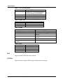
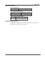
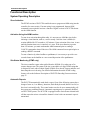
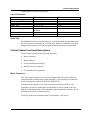
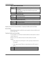
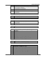
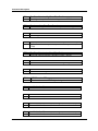
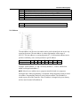
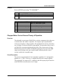
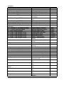
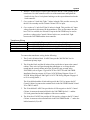
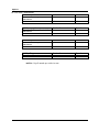
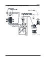
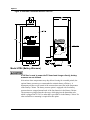
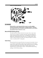
Functional Description The thresholds are in the following table. Table 18 Thresholds Input AC fail internal AC fail external TR Battery 12 V Battery 48 V Intrusion Stuck Relay Detect Threshold 57 Vac +/- 5% 40 Vrms +/- 1% 12.7 V +/- 3% 43.5 V +/- 3% Door Open relays off & current = 50-300 A 1.0-3.4 V Pushbutton Motor fuse Local Activation Time 57 sec +/- 1 2.2 sec + 1 sec x site # 20 sec 20 sec 555 mS 222 mS 5 sec 10 sec Growl Test The Standard Growl Test runs the rotator for 12 seconds and the chopper motor until the sensors latch or a maximum of 2 seconds. This function is commonly used when doing periodic testing to verify proper operation while generating minimal sound. Control Cabinet Functional Descriptions The dc Control Cabinet has the following main parts: Motor Contactors Battery Charger Power Distribution and Fusing Radio Transceiver (optional) FC Controller Board (optional) Motor Contactors Two 200 A motor contactors are used for switching the 48 Vdc power to the siren motor through K2, and the rotator motor through K1. The contactors are controlled by the relay outputs on the DCB, DCFCB, and DCFCTB. A third optional contactor, K3, is used to switch between the rectified 48 Vdc provided by the 240 Vac transformer option and the 48 Vdc provided by the four batteries in the battery cabinet. The switching occurs automatically when the 48 Vdc provided by the 240 Vac transformer fails. The wiring to the siren and rotator motor is protected by a 200 A fuse. DCB, DCFCB, and DCFCTB Models 19