1
HDA
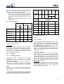
Pressure quantity of
balance liquid varies
Rough pump running
Excessive rise of
temperature inside the
Excessive leakage at the
shaft seal
Vibration during pump
operation
Leakage at the pump
Increase in bearing
temperature
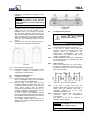
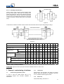
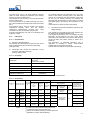
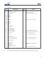
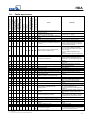
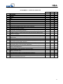
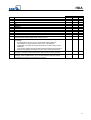
Faults and causes
Excessive pump
discharge pressure
Motor is overloaded
Pump delivers
insufficient flow rate
10.
Remedy 1)
Cause
•
Pump delivers against an excessively high
discharge pressure.
Re-adjust duty point.
•
Excessively high back pressure.
Check plant for impurities. Increase the
speed (turbine, I.C. engine).
•
•
•
•
•
•
•
•
•
•
•
•
•
Pump is warped or sympathetic vibrations in
the piping.
•
•
•
•
Pump or piping are not completely vented or
primed.
Supply line or impeller clogged.
Formation of air pockets in the piping.
•
Suction head is too high / NPSH available
(positive suction head) is too low.
•
Increased axial thrust. 2)
•
Air intake at the shaft seal.
•
Reverse rotation
•
•
Motor is running on two phases only.
•
•
•
•
•
•
•
•
•
•
•
•
•
•
•
•
•
•
•
•
Speed is too low. 2)
Defective bearings.
Insufficient rate of flow.
Wear of internal pump parts.
Pump back pressure is lower than specified
in the purchase order.
Density or viscosity of the fluid pumped is
higher than stated in the purchase order.
Use of unsuitable materials.
Speed is too high.
•
•
•
•
Tie bolts/seals and gaskets.
•
Worn shaft seal.
•
Score marks or roughness on shaft
protecting sleeve.
•
Lack of cooling liquid or dirty cooling
chamber.
•
Vibrations during pump operation.
•
•
•
•
The unit is misaligned.
Insufficient or excessive quantity of lubricant
or unsuitable lubricant.
Non-compliance with specified coupling
distance.
Operating voltage is too low.
Rotor is out of balance .
•
•
•
•
•
•
Check balance liquid line
1)
The pump pressure must be released before attempting to remedy faults on parts which are subjected to pressure.
2)
Contact KSB.
3)
This fault can also overcome by modifying the impeller diameter.
Vent and/or prime.
Remove deposits in the pump and/or piping.
Alter piping layout. /Fit a vent valve.
Check pipeline connection and secure fixing
of pump; if required reduced the distance
between the pipe clamps. Fix the pipelines
using anti-vibration material.
Check / alter liquid level. /Fully open shut-off
valve in the suction head line. /Change
suction line, if friction losses in the suction
line are too high.
Check any strainers installed / suction
opening.
Observe permissible speed of pressure fall.
Correct rotor adjustment.
Fit new shaft seal. /Clean liquid passage.
Arrange a sealing liquid supply from an
outside source. /Or increase sealing liquid
pressure.
Interchange two of the phases of the power
supply cable.
Replace the defective fuse. Check the
electric cable connections.
Increase speed.
Fit new bearings.
Increase the minimum rate of flow.
Replace worn components by new ones.
Adjust duty point accurately. /Trim the
impellers.
2)
Change the Material combination.
Reduce the speed. 2) (applies to turbine
driven or I.C. engine driven pumps) 2) 3)
Tighten the bolts. /Fit new seals and
gaskets.
Fit new shaft seal.
Fit new shaft protecting sleeve. Fit new shaft
seal / check the balancing line.
Check the throttle bush / throttling sleeve
clearances.
Increase cooling liquid quantity. /Clean out
cooling chamber. /Purify / clean cooling
liquid.
Improve suction conditions. /Re-align the
pump. /Re-balance the impeller. /Increase
the pressure at the pump suction nozzle.
Check the coupling; re-align, if required.
Top up, reduce or change lubricant.
Correct distance according to the G.A.
Drawing.
Increase the voltage.
Clean the impeller. /Re-balance the impeller.
Check mode of pump running. /Check return
line. /Check pump pressures. / Chech rotor
clearances and balancing device.
31