1
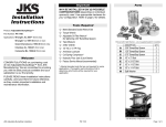
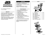
Welcome Installation Instructions CONGRATULATIONS on your purchase of a new JKS ACOS Pro™ system! At JKS Manufacturing, we are committed to providing you with the best products available and your satisfaction is our first priority. PLEASE READ these Installation Instructions carefully, and save them for future reference, as they contain important installation, operation and maintenance information. Before You Begin… 1. Familiarize yourself with the supplied parts as illustrated in the following column. Parts A B C D E F G H I J DESCRIPTION QTY Reinforcement Ring Main Body 5/16” x 1-1/4” Cap Bolt 5/16” Nylock Nut Adjuster Ring 3/8” x 1-1/4” Cap Bolt Isolator Pad Bump Shock Adapter Bump Shock Nut Bump Shock Assembly 2 2 12 12 2 2 2 2 2 2 2. Thoroughly read all procedures for your application to ensure you have the tools and experience necessary to complete this installation. Front Installation ► Pages 2-4 Rear Installation ► Pages 5-8 Product: ACOS Pro™ 3. If you are not completely comfortable with any of the procedures described on the following pages, do not attempt this installation. Contact the JKS Technical Department at (308) 762-6949 to locate a qualified installation specialist in your area. Part Number: PN 2700 Applications: Jeep Wrangler TJ, 1997-06 (front or rear) Jeep Grand Cherokee ZJ, 1993-98 (front only) Jeep Cherokee XJ, 1984-01 (front only) Jeep Comanche MJ, 1986-92 (front only) JKS ACOS Pro™ Installation PN 2700 Page 1 of 8 Front Installation Important MOST VEHICLES REQUIRE additional parts or modifications to accommodate the immediate increase in ride height provided by the ACOS Pro™ system. DO NOT EXCEED maximum range of adjustment – see illustration on page 3. INSTALLATION of this product is not reversible and should only be performed by an experienced mechanic or fabricator. Installation 1. REMOVE FRONT COIL SPRINGS Remove the front coil springs per the factory service manual instructions for your vehicle. HINT: A coil spring compressor is useful for removal. Depending on the application, it may be necessary to completely or partially remove any of the following components before spring can be free from upper mount. z Shock Absorber z Swaybar z Brake Line Hydraulic Floor Jack and Jack Stands Metric/Standard Socket Wrench Set Torque Wrench 1/4” & 5/16” Allen Wrenches Die Grinder with Cut-Off Wheel (or reciprocating saw) Grinding Wheel * Tape Measure 1/4” and 3/8” Drill Bits Transfer Punch (or equivalent) Spray Lubricant (WD-40 or similar) Anti-Seize Lubricant Medium Strength Threadlocker Coil Spring Compressor * Satin Black Spray Paint Factory Service Manual (recommended) Remove the factory rubber isolator pad from the upper coil spring retainer. 3. DRILL UPPER SPRING MOUNT Remove the Bump Shock Assembly (J), Bump Shock Nut (I), Bump Shock Adapter (H), Isolator Pad (G) and Adjuster Ring (E) from the Main Body (B) of the ACOS Pro™. Slide the Main Body (B) over the spring retainer z ABS Wire Tools Required HINT: On most vehicles the bump stop holder is secured to the upper spring retainer with a single bolt. However, on some Cherokee XJ and Comanche MJ models the bump stop holder is welded to the spring retainer. In this case, you will need to cut or grind away the flared portion of the bump stop holder before proceeding to Step 2. z Lower Suspension Arm until the flange rests flush against the upper spring mount. Hint: The Main Body must be perfectly centered over the spring retainer. z Track Bar z Steering Drag Link z Lower Spring Retainer Clip 2. PREPARE UPPER SPRING MOUNT Remove the rubber bump stop, bump stop holder and OE spacer (if equipped) from the upper spring retainer. Using the flange of the Main Body (B) as a template, accurately mark all six hole locations on the upper spring mount using a transfer punch or equivalent. Remove Main Body from spring mount. * Asterisk denotes tools that are not required for some applications. Thoroughly read instructions first to determine which tools will be required for your application. Using a 1/4” bit, drill a pilot hole at each hole location. Enlarge each hole with a 3/8” drill bit. Paint any exposed metal on the upper spring mount to prevent corrosion. JKS ACOS Pro™ Installation PN 2700 Page 2 of 8 4. CUT UPPER SPRING RETAINER The majority of the factory spring retainer must be permanently removed from the upper spring mount in order to install the ACOS Pro™. This modification is not reversible and should only be performed by an experienced mechanic or fabricator. Mark a location on the upper spring retainer that is 1” away from the upper spring mount. 5. INSTALL MAIN BODY OF ACOS PRO™ ON UPPER SPRING MOUNT Place the Reinforcement Ring (A) above the upper spring mount and align the mounting holes. Hint: On Cherokee XJ and Comanche MJ models it will be necessary to first remove a factory mounting stud for the air intake box that interferes with the Reinforcement Ring. A die grinder with cut-off wheel is useful for removing the mounting stud. Position the Main Body (B) against the bottom of the upper spring mount and align the mounting holes. 6. SET ADJUSTER RING FOR DESIRED RIDE HEIGHT Apply spray lubricant to threads of Main Body (B). Install Adjuster Ring (E) by threading clockwise onto Main Body (B). Slide Isolator Pad (G) onto Main Body until flush with Adjuster Ring (E). IMPORTANT: Vehicle ride height is determined by measuring the distance between the top of Main Body and bottom of Isolator Pad, and then subtracting 3/4” (0.75 in.). Cut away the upper spring retainer as indicated in the picture below. HINT: A die grinder with cut-off wheel or reciprocating saw is useful for cutting upper spring retainer. Insert a 5/16” x 1-1/4” Cap Bolt (C) through each hole. Loosely secure with a 5/16” Nylock Nut (D) from above the spring mount. HINT: When installed correctly, the Reinforcement Ring (A) and Main Body (B) will sandwich the upper spring mount. Once all six bolts have been installed, tighten the 5/16” Nylock Nuts (D) to 40 ft-lbs. using a torque wrench. X” – 3/4” = RIDE HEIGHT * * Represents increase in ride height over OE suspension WARNING DO NOT EXCEED MAXIMUM RANGE OF ADJUSTMENT ADJUSTMENT RANGE MINIMUM: 1-3/8” (1.375 in.) MAXIMUM: 3-1/4” (3.250 in.) Rotate Adjuster Ring (E) to desired position and tighten the recessed 3/8” x 1-1/4” Cap Bolt (F) to lock in place. JKS ACOS Pro™ Installation PN 2700 Page 3 of 8 7. INSTALL BUMP SHOCK ON MAIN BODY OF ACOS PRO™ Apply a drop of medium strength thread locking compound to bottom few threads of Main Body (B). Completely thread the Bump Shock Adapter (H) onto Main Body (B) until snug. Apply anti-seize lubricant to threads of Bump Shock Assembly (J). Completely thread the Bump Shock Nut (I) onto Bump Shock Assembly (J). Completely thread Bump Shock Assembly (J) with Bump Shock Nut (I) into Bump Shock Adapter (H) as far as possible. 9. ADJUST BUMP SHOCK POSITION The ideal bump shock position is determined by the vehicle suspension and varies for each application. To properly set the bump shock position for your vehicle, you must first decide the point at which suspension compression should be limited. Take into consideration coil springs, shock absorbers, tire clearance, or any other factors that cause the vehicle to bottom out. IMPORTANT: Because it replaces the original rubber bump stop, the bump shock should determine the limit of compression travel. The bump shock should be fully compressed when the suspension reaches maximum desired compression. With the vehicle on level ground and the suspension at full droop, extend the Bump Shock Assembly (J) to the desired position. Once the Bump Shock Assembly (J) is properly adjusted for your application, lock in place by turning the Bump Shock Nut (I) clockwise until it contacts the Bump Shock Adapter (H). 8. RE-INSTALL FRONT COIL SPRINGS Re-install the front coil springs per the factory service manual instructions for your vehicle. HINT: A coil spring compressor is useful for installation. Also re-install any of the components that were removed during Step 1 of this installation. IMPORTANT: The suspension must be fully cycled to test for bump shock alignment and interference issues before the vehicle can be safely operated. The bump shock must contact the center portion of the lower spring pad at full compression, and there should be no interference between the bump shock and coil spring at full extension. Operation Ride Height & Bump Shock Adjustments Future ride height and bump shock adjustments should be made with NO LOAD on the front coil springs, and the suspension at FULL DROOP. NEVER TURN Adjuster Ring (E) while under tension and ALWAYS APPLY SPRAY LUBRICANT to threads of Main Body (B) or Bump Shock Assembly (J) before adjusting. Bump Shock Pressure The Bump Shock Assembly (J) is pre-charged with the proper amount of Nitrogen gas to suit most applications. IT SHOULD NOT BE NECESSARY TO ADJUST BUMP SHOCK PRESSURE ON MOST VEHICLES. The Nitrogen charge is factory preset at 150 psi. For applications that require a higher or lower compression rate, the gas pressure can be manually adjusted to a minimum of 100 psi and a maximum of 200 psi. To adjust pressure, the bump shock assembly must be removed from the vehicle. Nitrogen pressure is adjusted through the Schrader valve on top of the bump shock. Care should be taken when discharging the bump shock to ensure that no oil is lost. Most shops that service offroad racing or motorcycle shock absorbers can adjust bump shock pressure. If you encounter any interference issues, contact JKS Manufacturing immediately for technical assistance. JKS Technical Department Phone (308) 762-6949 E-mail [email protected] ATTENTION INSTALLER Maintenance IMPORTANT NOTE REGARDING SHOCK ABSORBERS Regular cleaning with pressurized water is recommended to maximize ease of operation and reliability. To prevent the coil springs from becoming unseated during maximum suspension extension, correct length shock absorbers must be installed. JKS ACOS Pro™ Installation PN 2700 Page 4 of 8 Rear Installation Important MOST VEHICLES REQUIRE additional parts or modifications to accommodate the immediate increase in ride height provided by the ACOS Pro™ system. COMPATIBLE WITH 4” REAR COIL SPRINGS or taller. This product can not be installed with springs shorter than 4”. DO NOT EXCEED maximum range of adjustment – see illustration on page 7. INSTALLATION of this product is not reversible and should only be performed by an experienced mechanic or fabricator. Tools Required Plasma Cutter Hydraulic Floor Jack and Jack Stands Metric/Standard Socket Wrench Set Torque Wrench 1/4" & 5/16” Allen Wrenches Machinist Calipers (or equivalent) Tape Measure Band Saw (or equivalent) * 16TPI Thread Restoring File (or equivalent) * 1/4” and 3/8” Drill Bits Transfer Punch (or equivalent) Spray Lubricant (WD-40 or similar) Anti-Seize Lubricant Medium Strength Threadlocker Coil Spring Compressor * Satin Black Spray Paint Factory Service Manual (recommended) Installation 1. REMOVE REAR COIL SPRINGS Remove the rear coil springs per the factory service manual instructions for your vehicle. HINT: A coil spring compressor is useful for removal. Remove the Bump Shock Assembly (J), Bump Shock Nut (I), Bump Shock Adapter (H), Isolator Pad (G), and Adjuster Ring (E) from the Main Body (B) of the ACOS Pro™. Turn the Main Body (B) upside down and position the threaded end over the protruding portion of the upper spring mount. Depending on the application, it may be necessary to completely or partially remove any of the following components before spring can be free from upper mount. z Shock Absorber z Swaybar z Brake Line z Track Bar Mark a straight and level line around the 2. PREPARE UPPER SPRING MOUNT The factory upper spring mount and bracket must be modified in order to install the ACOS Pro™. This modification is not reversible and should only be performed by an experienced mechanic or fabricator. protruding portion of the upper spring mount where the diameter is exactly 2-1/4”. HINT: Machinist calipers are useful for measuring diameter. Remove the rubber bump stop and bump stop holder from the upper spring mount. Remove the factory rubber isolator pad from the upper coil spring mount. * Asterisk denotes tools that are not required for some applications. Thoroughly read instructions first to determine which tools will be required for your application. JKS ACOS Pro™ Installation PN 2700 Page 5 of 8 Cut away the center portion of the upper spring mount as indicated in the picture below. HINT: A plasma cutter is useful for cutting the upper spring mount. Plasma cutting experience and a very steady hand are necessary to ensure a clean, accurate cut. Use extreme caution when operating a plasma cutter near the fuel tank or any fuel lines. 3. SHORTEN MAIN BODY OF ACOS PRO ™ On vehicles with 4.0 - 5.5” rear coil springs, it will be necessary to shorten the Main Body (B) to provide sufficient clearance between the Bump Shock Assembly (J) and axle pad. Disregard this step on vehicles with 6.0” springs or taller, as this modification will not be necessary. Measuring 1.5” from the threaded end, mark a line on the Main Body (B). 4. DRILL UPPER SPRING MOUNT Temporarily install the Bump Shock Adapter (H) and Bump Shock Assembly (J) on Main Body (B) of ACOS Pro™. Thread Bump Shock Assembly into Main Body completely. Place the Main Body (B) against the upper spring mount ensuring that the top of the Bump Shock Assembly (J) passes cleanly through the large hole created in section 2. HINT: Main Body (B) must be perfectly centered over spring mount to prevent obstruction of Bump Shock Assembly (J) threads. With the center portion of the upper spring mount cut away, a second hole must be cut through the attached spring mount bracket. Begin by marking a 2-1/4” diameter hole in the bracket using the hole in the spring mount as a guide. HINT: Mark the hole location carefully – the hole in the spring mount bracket must be concentric to the hole cut into the spring mount. Insert your cutting tool into the upper spring mount hole and cut the second 2-1/4” diameter hole through the spring mount bracket. HINT: Once again, a plasma cutter is the best choice for cutting the spring mount bracket Remove the excess threaded portion by cutting completely through the Main Body (B) at the location marked in the previous step. HINT: A band saw is useful for cutting the Main Body (B), although a sharp hack saw with an appropriate fine tooth blade or cutting wheel may also be used. Use extreme care to avoid damaging remaining threads. Inspect end of Main Body (B) for damaged threads and repair as needed. HINT: A 16TPI thread restoring file or equivalent is useful for repairing threads. JKS ACOS Pro™ Installation PN 2700 Page 6 of 8 Using the Main Body (B) as a template, accurately mark all six hole locations on the upper spring mount using a transfer punch or equivalent. HINT: Hole locations should align with spring mount bracket as indicated below. 5. INSTALL MAIN BODY OF ACOS PRO™ ON UPPER SPRING MOUNT Position the Main Body (B) against the bottom of the upper spring mount and align the mounting holes. 6. SET ADJUSTER RING FOR DESIRED RIDE HEIGHT Apply spray lubricant to threads of Main Body (B). Install Adjuster Ring (E) by threading clockwise onto Main Body (B). Slide Isolator Pad (G) onto Main Body until flush with Adjuster Ring (E). IMPORTANT: Vehicle ride height is determined by measuring the distance between the top of Main Body and bottom of Isolator Pad, and then subtracting 1/4” (0.25 in.). Insert a 5/16” x 1-1/4” Cap Bolt (C) through each hole. Loosely secure with a 5/16” Nylock Nut (D) from above the spring mount. HINT: It is not necessary to install the supplied Reinforcement Ring (A) on rear applications. Once all six bolts have been installed, tighten the 5/16” Nylock Nuts (D) to 40 ft-lbs. using a torque wrench. X” – 1/4” = RIDE HEIGHT * * Represents increase in ride height over OE suspension WARNING DO NOT EXCEED Using a 1/4” bit, drill a pilot hole at each hole location. Enlarge each hole with a 3/8” drill bit. MAXIMUM RANGE OF ADJUSTMENT Paint any exposed metal on the upper spring ADJUSTMENT RANGE mount to prevent corrosion. MINIMUM: 1-3/4” (1.750 in.) MAXIMUM: 3-5/8” (3.625 in.) ** ** MAXIMUM: 2-1/8” (2.125 in.) if Main Body was shortened 1-1/2” in step 3 Rotate Adjuster Ring (E) to desired position and tighten the recessed 3/8” x 1-1/4” Cap Bolt (F) to lock in place. JKS ACOS Pro™ Installation PN 2700 Page 7 of 8 7. INSTALL BUMP SHOCK ON MAIN BODY OF ACOS PRO™ Apply a drop of medium strength thread locking compound to bottom few threads of Main Body (B). Completely thread the Bump Shock Adapter (H) onto Main Body (B) until snug. Apply anti-seize lubricant to threads of Bump Shock Assembly (J). Completely thread the Bump Shock Nut (I) onto Bump Shock Assembly (J). Completely thread the Bump Shock Assembly (J) with Bump Shock Nut (I) into Bump Shock Adapter (H) as far as possible. 9. ADJUST BUMP SHOCK POSITION The ideal bump shock position is determined by the vehicle suspension and varies for each application. To properly set the bump shock position for your vehicle, you must first decide the point at which suspension compression should be limited. Take into consideration coil springs, shock absorbers, tire clearance, or any other factors that cause the vehicle to bottom out. IMPORTANT: Because it replaces the original rubber bump stop, the bump shock should determine the limit of compression travel. The bump shock should be fully compressed when the suspension reaches maximum desired compression. With the vehicle on level ground and the suspension at full droop, extend the Bump Shock Assembly (J) to the desired position. Once the Bump Shock Assembly (J) is properly adjusted for your application, lock in place by turning the Bump Shock Nut (I) clockwise until it contacts the Bump Shock Adapter (H). 8. RE-INSTALL REAR COIL SPRINGS Re-install the rear coil springs per the factory service manual instructions for your vehicle. HINT: A coil spring compressor is useful for installation. Also re-install any of the components that were removed during Step 1 of this installation. ATTENTION INSTALLER IMPORTANT NOTE REGARDING SHOCK ABSORBERS To prevent the coil springs from becoming unseated during maximum suspension extension, correct length shock absorbers must be installed. IMPORTANT: The suspension must be fully cycled to test for bump shock alignment and interference issues before the vehicle can be safely operated. The bump shock must contact the center portion of the lower spring pad at full compression, and there should be no interference between the bump shock and coil spring at full extension. Operation Ride Height & Bump Shock Adjustments Future ride height and bump shock adjustments should be made with NO LOAD on the rear coil springs, and the suspension at FULL DROOP. NEVER TURN Adjuster Ring (E) while under tension and ALWAYS APPLY SPRAY LUBRICANT to threads of Main Body (B) or Bump Shock Assembly (J) before adjusting. Bump Shock Pressure The Bump Shock Assembly (J) is pre-charged with the proper amount of Nitrogen gas to suit most applications. IT SHOULD NOT BE NECESSARY TO ADJUST BUMP SHOCK PRESSURE ON MOST VEHICLES. The Nitrogen charge is factory preset at 150 psi. For applications that require a higher or lower compression rate, the gas pressure can be manually adjusted to a minimum of 100 psi and a maximum of 200 psi. To adjust pressure, the bump shock assembly must be removed from the vehicle. Nitrogen pressure is adjusted through the Schrader valve on top of the bump shock. Care should be taken when discharging the bump shock to ensure that no oil is lost. Most shops that service offroad racing or motorcycle shock absorbers can adjust bump shock pressure. Interference issues may exist on applications in which the rear axle has been moved rearward to increase the vehicle’s wheelbase. Resolving this problem may require removal of the entire upper spring mount from the chassis and re-welding it at the correct angle. If you encounter any interference issues, contact JKS Manufacturing immediately for technical assistance. JKS Technical Department Phone (308) 762-6949 E-mail [email protected] Maintenance Regular cleaning with pressurized water is recommended to maximize ease of operation and reliability. © 2009 JKS Manufacturing, Inc & Aftermarketing, LLC Revision Date 7/24/2009 JKS ACOS Pro™ Installation PN 2700 Page 8 of 8