1
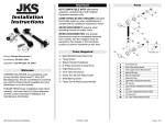
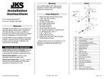
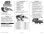
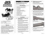
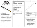
Parts Installation Instructions A B C D DESCRIPTION Alignment Tab Drill Guide Actuator Cable Assembly 72” Actuator Cable C1 5/16” Jam Nut C2 Star Washer C3 1/4” Hex Nut C4 Actuator Cable Stud C5 Wire Nut Connector PART # PN ESB101 PN ESB102 PN ESB103 PN 721245 QTY 1 1 1 1 1 1 2 1 3 Product: Electronic Swaybar Cable Conversion Part Number: PN 9500 Tools Required Application: Jeep® Wrangler JK, 2007+ Welcome Congratulations on purchasing a new Electronic ® Swaybar Cable Conversion from JKS Manufacturing. We are committed to providing you with the best products available and your satisfaction is our first priority. We hope you enjoy your JKS® purchase and are here to help if you still have questions after reviewing this safety information and instructions. Contact us online at www.jksmfg.com or by phone at 308-762-6949. JKS Electronic Swaybar Cable Conversion Installation Metric/Standard Socket Wrench Set Torque Wrench 1/2", 7/8” & 15/16” Open End Wrenches Electric Drill with the following bits • 1/8” • 3/16” • 5/8” • Size I (0.272”) • 9/32” 5/16” -24 Thread Tap C Clamp (2” with 2” throat or larger) 1/8” Steel Punch Wire Cutters Flat Head Screwdriver WD-40 (or similar lubricant for cutting threads in aluminum) Blue Painter’s Masking Tape (or equivalent) Medium Strength Thread Locking Compound Factory Service Manual (recommended to remove and reinstall sway bar assembly on vehicle) Always Wear Protective Gear Safety glasses and protective gloves are required. PN 9500 Page 1 of 9 Important Product Safety Information Higher Rollover Risk For your safety and the safety of others, please read all instructions and warnings in this pamphlet and your Jeep® owner’s manual and off road driving supplement before attempting installation. Within these instructions the following signal words refer to important product safety information: Indicates hazards or unsafe situations which could result in severe personal injury or death. Indicates hazards or unsafe situations which could result in property damage or minor to moderate personal injury. Modifying your Jeep® to improve off-road performance may result in vehicle handling different than as factory equipped, including increased ride-height and/or chassis articulation; reduced lateral stability and higher risk of roll-over or other accident. Also, owner’s choice of larger tire and wheel combinations may require additional braking force or increased stopping distances. To reduce risk of serious injury and accident: Careful attention is required to this operation that generally does not relate to personal injury, although damage to your JKS product or other property may result if you fail to follow instructions. JKS Electronic Swaybar Cable Conversion Installation Choose modifications that balance your actual highway & off-road use. Avoid sharp turns, abrupt maneuvers or steep side-cambers. Avoid other maneuvering conditions which may cause the vehicle to trip, roll, lose traction or compromise your ability to safely brake in an emergency. Routinely inspect your vehicle components for unusual wear or off-road damage. Repair or Replace any unserviceable components before use. Do not modify or combine body lifts with other mechanical lifts contrary to manufacturers’ or Jeep® recommendations & warnings. Acquaint any other drivers with your vehicle modifications and handling. Always wear seat belts and/or appropriate offroad restraints, reduce your speed, Tread Lightly©. PN 9500 Page 2 of 9 Locate the seven rivets that secure the plastic Professional Installation Only plunger housing from the electric motor housing. Pull the electric motor and gearbox from the motor housing so that you can access the wires. This product should only be installed by a professional mechanic or individual with considerable technical experience and the proper tools. Stay Connected On-road On-highway safety is enhanced by controlling body roll. Never disconnect swaybar when operating on public roads. Installation 1. DISSASSEMBLY Remove electronic swaybar assembly from Using a wire cutter, cut the wires close to the Using a 1/8” drill bit, drill out all seven rivets. Don’t drill all the way through. Just break through the lip and tap the remaining part of the rivet out using a 1/8” steel punch. electric motor and gearbox so that the remaining wires from the motor housing are long enough to work with. Discard electric motor and gearbox as they will not be used during reassembly. vehicle per the factory service manual instructions for your vehicle. Using the 3 supplied Wire Nut Connectors (D), Remove the three M10 bolts that secure the electric motor housing to the main gear housing. Separate the motor housing from the gear housing as pictured below. Separate the plastic plunger housing from the motor housing. cap off the red and white wires separately. Then combine the 2 black wires and cap them off using the remaining wire nut. Hint: Do not strip insulation from ends of wires. RED WHITE BLACK Remove and discard all of the parts between BLACK the plunger housing and electric motor housing. These parts will not be reused. JKS Electronic Swaybar Cable Conversion Installation PN 9500 Page 3 of 9 Place the plastic plunger housing on a workbench to prevent any damage to the housing during the next step. Discard clock spring as it will no longer be used. Using a 9/32” drill bit, drill out the plastic threads from the plunger mechanism. Separate plunger mechanism from plunger housing. Locate and remove the brass bushing and flat washer from the plastic plunger housing. Unscrew worm shaft from plunger mechanism and discard as it will no longer be used. Using a 1/8” punch, carefully drive the worm shaft through the worm shaft coupler. Spring Under Tension This will free the clock spring underneath the worm shaft coupler causing it to rapidly unwind. Use caution to prevent injury to yourself from unwinding spring. JKS Electronic Swaybar Cable Conversion Installation Locate the internal threads inside the plunger Remove the five M10 bolts that secure the two halves of the main gear housing together. mechanism into which the worm shaft was threaded. PN 9500 Page 4 of 9 Separate the main gear housing and retain the gasket seal for reassembly. Remove the grease from the stepped portion of the housing as pictured to prepare for drilling. Insert the Drill Guide (B) into spring pocket in housing as pictured. Use a clamp to hold the Drill Guide in position during drilling. Save the grease as it will be reapplied during final assembly. Remove the coil spring, engagement fork and splined collar from the main gear housing. Retain these parts for reassembly. Using a 3/16” drill bit, insert the drill into the Protect the rest of the housing from debris by covering with blue masking tape or equivalent. guide and drill a pilot hole through the housing. Remove the Drill Guide and enlarge the hole Locate the supplied steel Drill Guide (B). JKS Electronic Swaybar Cable Conversion Installation PN 9500 using a size I (0.272”) drill bit. Page 5 of 9 Using a 5/16” -24 thread tap, cut threads in the enlarged hole. Use WD-40 or appropriate lubricant during the tapping process and hold the tap in line with the hole. Every few turns, back the tap out to clear away any metal chips. Clean up all of the metal chips. Using a 3/16” drill bit, insert the drill into the guide and drill a pilot hole through the engagement fork. 2. PREPARE CABLE FOR INSTALLATION Before installing Actuator Cable (C), the 5/16” Jam Nut (C2) and Star Washer (C3) on the threaded end must be reversed. To prevent the star washer from getting lost during shipping, it was placed on the actuator cable before the jam nut. First remove the two 1/4” Hex Nuts (C4) from the Actuator Cable Stud (C5). Set both nuts aside for the moment. Next remove the larger 5/16” Jam Nut (C2) and Star Washer (C3) from the cable. Then fully thread the jam nut back onto the cable, followed by the star washer. With the housing drilled and tapped, you are now going to drill a hole in the engagement fork so the cable can pass through it. Use the same Drill Guide (B) as used previously. Insert the base of the Drill Guide (B) into the Remove the Drill Guide and enlarge the hole using a 9/32” drill bit. JKS Electronic Swaybar Cable Conversion Installation PN 9500 AFTER Clean up all of the metal chips. BEFORE plunger pocket on the engagement fork as pictured. Use a clamp to hold the Drill Guide in position during drilling. Page 6 of 9 3. REASSEMBLY Insert threaded end of Actuator Cable (C) into Insert the supplied small rectangular Alignment Tab (A) into plunger mechanism directly over the drilled hole. threaded hole in housing. Thread the cable by hand until the 1/2” Jam Nut (C2) restricts it from being threaded any further. Using a 7/16” wrench, tighten the 1/4” Hex Nut (C4) just enough (approximately 1/32”) to slightly compress the coil spring inside the plunger mechanism. Thread the remaining 1/4” Nut onto the stud until it bears against the first nut, and then tighten with wrench to lock the nuts together. Using a 1/2” open end wrench, tighten Jam Nut (C2) against Star Washer (C3) until snug to secure the Actuator Cable to the housing. Slide the plunger mechanism onto the Actuator Cable Stud (C5) and press fully into the plunger pocket in engagement fork. Reapply original grease to coil spring, splined collar and engagement fork and then reassemble as pictured below. Hint: Make sure splines on collar are well lubricated. Pull the threaded end of the cable to remove Reinstall the lubricated assembly in the main gear housing. Make sure the Actuator Cable Stud (C5) passes through the hole you drilled in the engagement fork, and that the assembly is pushed fully into the housing. JKS Electronic Swaybar Cable Conversion Installation any slack and thread one of the 1/4” Hex Nuts (C4) that was originally installed on the actuator cable back onto the stud. Tighten nut by hand. PN 9500 Before continuing reassembly, bench test the Cable Conversion by pulling the handle on the Actuator Cable (C) to make sure the engagement fork pulls the splined collar completely onto the splined gear as pictured below. Place the original gasket seal on the mounting flange of one of the main gear housing halves. Make sure mating flange on both halves of the housing are completely clean and free of any debris. Page 7 of 9 Clock the splined collar with the splined gear on the opposite housing half and mate the two halves of the housing back together, while making sure the gasket remains in place and properly aligned. Mate the motor housing to the main gear housing. Using a 5/8” drill bit, drill a hole through the inner fender where the T-handle will be mounted. Using a flat head screwdriver, remove the small machine screw from the center of the Thandle. Secure the housings together by reinstalling the original three M10 bolts. Secure the two gear housing halves together by reinstalling the original five M10 bolts. Using a torque wrench, tighten all M10 bolts to 40 ft-lbs. Before continuing reassembly, bench test the Cable Conversion once more by pulling the handle on the Actuator Cable (C) and twisting each end of the swaybar to check for engagement and disengagement. Reposition plastic plunger housing onto motor housing. No hardware will be used to secure the plunger housing, as flange will be sandwiched between motor housing and main gear housing. JKS Electronic Swaybar Cable Conversion Installation Using a torque wrench, tighten all M10 bolts to 40 ft-lbs. Reinstall electronic swaybar assembly on vehicle per factory service manual instructions. 4. MOUNT T-HANDLE Choose a location to mount the T-handle end Next remove the large collar nut from the Actuator Cable (C) using a 7/8” wrench. Remove the star locking washer from the cable but leave the remaining jam nut in place. of the Actuator Cable (C). We suggest mounting the Thandle on the inner fender as pictured below. This location is easily accessible and clear of obstructions. PN 9500 Page 8 of 9 Insert the threaded end of the Actuator Cable (C) through the mounting hole from inside the engine compartment. If you encounter any problems with your installation and setup, please contact JKS Manufacturing for technical assistance. JKS Technical Support Avoid Cable Interference It is the installer’s responsibility to route the Actuator Cable (C) from the swaybar assembly to the T-handle along a path that will not interfere with any of the vehicle’s moving parts. Avoid contact with radiator hoses, electrical wires or brake lines. Secure the cable to the vehicle using wire ties or equivalent. With the cable properly routed, reinstall the Phone (308) 762-6949 E-mail [email protected] 2012 JKS Manufacturing, Inc & Aftermarketing, LLC Revision Date 11/7/2012 star locking washer and thread the large collar nut onto the protruding threads of the Actuator Cable (C) and finger tighten. Using a 7/8” wrench, tighten the collar nut until it bottoms out on the Actuator Cable (C). It may be necessary to loosen the jam nut to allow full engagement of collar nut. With the collar nut installed, tighten the jam nut against the star washer using a 15/16” open end wrench until the Actuator Cable (C) is securely mounted to the inner fender. Apply a drop of thread locking compound to the small machine screw and reinstall the Thandle onto the cable. Fully cycle the suspension and steering to make sure the Actuator Cable (C) is safely secured. JKS Electronic Swaybar Cable Conversion Installation PN 9500 Page 9 of 9