1
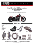
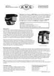
25 Railroad Ave
PO Box 11
Pine Bush, NY 12566
Instruction 106-6005
9-1-09
Installation Instructions For Lloydz Motorworkz
Billet Air Cleaner Kit for Victory® Motorcycles
Kit Contents:
• Billet backplate • Billet top cover
• Qty of 3 - M6 fasteners • Gasket
• Breather hose
• Qty of 4 - Hose clamps
• Filter Element
• 243 Blue Loctite®
• Wire tie
• Straight breather fitting
Special Tool Requirements
• PVC Pipe Wire Saw – Available from your local hardware store
• Victory® Service Manual – Available through Polaris® dealers
The Lloydz Motorworkz billet air cleaner kit is intended for all Victory® 2008 and up models except Vision™, Cross Country™, and Cross Roads™.
WARNING
••The safety of the motorcycle rider is dependent on proper installation of this product. If you are not certain of your capabilities or do not
••
have the correct tools for this installation, please consult a dealer to have it done. Improper installation of this product could result in
injury or death to the rider.
Be sure to disconnect the battery of your motorcycle before starting on this procedure. Accidental starting of the motorcycle could cause
injury to you or others around you during the installation.
Disassembly
Seat and Gas Tank Removal
1 – Disconnect the negative battery cable from the motorcycle and route it away from any metal parts in the area.
2 – Remove the seat and gas tank from the Victory® motorcycle following your Victory service manual for the specific model you are performing
the work on.
Key Switch Cover and Coil Mounting Bracket Removal
1 – Remove the ignition key switch cover by pulling outward on it. Picture 2 below illustrates the key switch cover.
Key Switch Cover
Picture 2
2 – Remove the four socket head cap screws from the ignition and coil mounting bracket that holds the bracket to the front and rear heads.
Picture 3 below points out the location of the four socket head cap screws.
Socket Head Cap Screws
Picture 3
3 – With the bracket free from the front and rear head unplug the spark plug wires at the coil.
4 – Disconnect the coil and ignition switch at the connectors freeing them from the primary wiring harness.
Idle Air Control Hoses and Throttle Position Sensor Removal
1 – Disconnect the Throttle Position Sensor (TPS) at the connector leaving the TPS attached to the throttle body. Picture 4 next page points out
the TPS connector.
2 – Remove the Idle Air Control (IAC) supply hose from the air box.
Note: Leave the 1.500” rubber hose attached to the hard plastic IAC supply hose. Picture 4 points out the IAC air supply hose and the 1.500” rubber hose.
3 – Remove the front Idle Air Control (IAC) air delivery hose from the rubber 90° fitting that leads into the front intake bore on the throttle body.
Leave the 90° rubber fitting attached to the throttle body. Picture 4 points out the IAC front delivery hose.
4 – Remove the rear IAC air delivery hose from the rubber “T” fitting that leads into the rear intake bore on the throttle body. Leave the rubber “T”
fitting attached to the throttle body. Picture 4 points out the IAC rear delivery hose.
2
1.500”
Rubber Hose
IAC Rear Delivery Hose
TPS Connector
IAC Front Delivery Hose
IAC Supply Hose
Picture 4
Idle Air Control Cover and IAC Mounting Bracket Removal
1 – Moving to the opposite side of the motorcycle, remove the IAC cover from the motorcycle. Picture 5 below illustrates the IAC cover.
IAC Cover
Picture 5
2 – Disconnect the IAC from the main wiring harness at the connector pointed out in Picture 6 below.
3 – Disconnect and remove the fuel supply hose at the connector pointed out in Picture 6.
4 – Remove the four socket head cap screws from the IAC mounting bracket that holds the bracket to the front and rear heads. Picture 6 points
out the location of the four socket head cap screws.
5 – Remove the IAC mounting bracket and the IAC supply and delivery hoses all in one piece.
IAC Connector
Fuel Supply Hose
Socket Head Cap Screws
Socket Head Cap Screws
Picture 6
3
Throttle Body Removal
1 – Remove the throttle cables from the throttle body following your Victory® service manual for the specific model you’re performing the work on.
2 – Remove the four socket head cap screws from the throttle body. Picture 7 and Picture 8 below point out the socket head cap screws that need
to be removed.
Note: The four socket head cap screws that are removed will be used for attaching the new Air Cleaner.
Picture 7
Socket Head Cap Screws
Picture 8
Socket Head Cap Screws
3 – Remove the throttle body from the motorcycle by sliding it out from the right side (throttle cable side).
4 – With the throttle body removed, slide a large piece of clean plastic between the air box and the rubber intake manifold as illustrated in Picture 9
below. This will help keep any debris from entering into the motor.
Note: Covering the intake manifold must be done before you move on.
4
Picture 9
Preparation for Victory® Air Box Removal
1 – Moving to the top side of the motorcycle, locate the breather hose and remove it from the air box. Picture 10 below illustrates the breather
hose connected to the air box.
2 – Cover the end of the breather hose so no debris can enter the opening.
Breather
Hose
Picture 10
Note: A small plastic bag with a rubber band works well for this as illustrated in Picture 11 below.
3 – Detach the wiring harness from the right side of the frame as pointed out in Picture 11 below.
4 – Masking tape should be applied to the frame of the motorcycle as illustrated in Picture 11 to reduce the risk of scratching the frame when
removing the stock air box.
Wiring
Harness
Masking
Tape
Masking
Tape
Picture 11
Breather Hose Covered
5
Removing the Victory® Air Box
1 – The use of a PVC pipe wire saw as illustrated in Picture 12 below works best for removal of stock Victory air box.
Picture 12-PVC Wire Saw
2 – Remove the air filter cover and the air filter element from the stock Victory air box
3 – Thread the wire saw between the frame rails as illustrated in Picture 13, 14, and 15 below.
Picture 14
Picture 13
Picture 15
Wire Saw
WARNING
Always wear eye protection while cutting or sawing to avoid injury to the eyes.
4 – Before making the first cut make certain you are wearing safety glasses or protective eyewear. With the wire saw in place, make sure there are
no wires or cables between the wire saw and the air box; work the saw back and forth cutting the air box from the top down and at an angle
toward the Idle Air Control plastic supply barb, cutting the air box into two pieces. Once the first cut is made, the rear section of the air box
should be removed.
5 – Making the second cut. With the rear section of the air box removed, thread the wire saw in the rear of the air box and through the opening
in the front of the air box, the air supply slot, and back out on the outside of the air box as illustrated in Picture 16 next page. Make sure
there are no wires or cables between the wire saw and the air box, now pull the wire saw back and forth cutting the right side section out
of the air box.
6 – Making the third cut. Thread the wire saw in the rear of the air box and through the opening in the front of the air box, the air supply slot, and
back out on the outside of the air box as illustrated in Picture 17 next page. Make sure there are no wires or cables between the wire saw and
the air box, now pull the wire saw back and forth cutting the left side section out of the air box. The front section of the air box can now be
removed from the motorcycle.
6
Wire Saw
Wire Saw
Picture 16
Picture 17
7 – Now that the air box is removed, clean up all of the plastic shavings on and around the motorcycle with the plastic sheeting in place so no
debris enters the intake.
WARNING
Always wear eye protection when removing and cleaning plastic shavings from the work area to avoid injury to the eyes.
Note: Clean rags work well for removing debris from the frame rails and then follow up with compressed air. Once the motorcycle is free of debris, sweep
the floor so you have a clean work area before moving on to the next step.
Installation
Installing the Lloyd’z Motorworkz Air Cleaner Assembly
1 – Locate the backplate, top cover plate, throttle body gasket, M6 fasteners, 243 Blue Loctite®, and filter element in the air cleaner kit as illustrated
in Picture 18 below.
2 – Remove the tape from the frame rails as well as the plastic sheeting covering the throttle body.
3 – Place the throttle body back on top of the rubber intake manifold making certain the O-ring is still in the rubber intake manifold.
1- Backplate
2- Filter Element
3- M6 Fasteners
4- Throttle Body Gasket
5- 243 Loctite®
6- Top Cover Plate
Picture 18
4 – With the throttle body in position, place the supplied gasket on top of the throttle body.
Note: The throttle body gasket is designed to be installed dry. Do not use any type of sealer.
5 – Locate the four socket head cap screws that were removed from the throttle body and stock air box at disassembly. Clean the threads and
apply 243 Blue Loctite® on them.
6 – Locate the backplate and place it on top of the throttle body making certain the throttle body gasket is captured between the throttle body
and the backplate.
7
7 – Install the four socket head cap screws up through the intake manifold, throttle body, and throttle body gasket. Thread the four socket head
cap screws in to the backplate, making certain the gasket is captured between the throttle body and the backplate. Hand tighten evenly in a
cross pattern. Once hand tightened finish torque to 72-96 inch pounds.
8 – Locate the pre-formed filter element. Place the filter into the machined groove on the backplate.
9 – Locate the top cover plate. Place the top cover plate on top of the filter element making certain that it fits into the machined groove in to the
top cover plate. Look all the way around the air cleaner assembly and make certain that the filter is positioned evenly into top cover plate and
the backplate.
10 –Locate the supplied Qty 3 - M6 fasteners. Apply 243 Blue Loctite® to the threads and hand tighten evenly into the top cover plate. Finish torque
fasteners to 72-96 inch pounds.
11–Re-secure the wiring harness to its original location on the right side frame rail.
Idle Air Control Bracket, Supply and Delivery Hose Installation
1 – With the Idle Air Control (IAC) bracket, supply and delivery hose assembly on your work bench, measure back .500” from the end of the front
and rear air delivery hoses and mark with a piece of masking tape as illustrated in Picture 19 below.
Note: The tape that is placed on the air delivery lines will be your depth gauge for installing lines into the front 90° and rear “T” rubber fittings that
connect to the throttle body. If the air delivery lines are pushed to far into the rubber fittings they may bottom out and restrict air flow causing improper
function of the IAC.
Masking Tape
.500"
.500"
Picture 19
2 – Route the air supply and air delivery lines between the cylinders and to the left side of the motorcycle just as they were routed before
disassembly. Mount the IAC bracket to its original location, to the front and rear heads, on the right side of the motorcycle with the four socket
head cap screws that were removed at disassembly. Tighten fasteners to 85 inch pounds.
3 – Push the front and rear air delivery lines in .500”, or up to the masking tape that was attached in step 1, into the rubber 90° and “T” fittings that
are attached to the throttle body. Once installed remove masking tape.
4 – Locate the black .660” spring clamp, illustrated in Picture 20 below, from the supplied hardware pack.
Picture 20
5 – Put the .660” spring clamp over the rubber hose on the air supply line.
6 – Push the rubber piece connected to the air supply line over the brass barb, closest to the throttle body, on the air cleaner.
7 – Move the spring clamp up over the hose barb as illustrated in Picture 21 next page.
8 – Reconnect the Throttle Position Sensor to the primary wiring harness at the connector.
8
Picture 21
Breather Hose Routing and Fuel Line Installation
1 – Locate the pre-formed breather hose, straight union fitting, 8” black wire tie, and the three dual wire spring clamps in the air cleaner kit as
illustrated in Picture 22 below.
Breather Hose Dual Wire Spring Clamp
Straight Union Fitting
Stock Breather Hose
Dual Wire Spring Clamp
Pre-formed
Breather Hose
Picture 22
2 – The preformed breather hose will need to be cut on both ends for proper fitment. Picture 23 below illustrates approximately where the
breather hose should be cut.
Note: It is best to cut long and test fit for proper length and clearance.
1.500"
7.625"
Picture 23
3 – Once the preformed breather hose has been cut, slide a dual wire spring clamp over each end.
9
Note: There are three dual wire spring clamps included in the kit. The two smaller diameter clamps go on the pre-formed breather hose. Push the 90° end
of the breather hose over the brass barb in the air cleaner backplate followed by the dual wire spring clamp as illustrated in Picture 24 below.
Picture 24
4 – Route the straight end of the breather hose between the air cleaner and the frame rail and over the top of the rear rocker cover.
5 – Locate the supplied straight union breather fitting.
Note: The barbed ends of the straight union fitting have two different outside diameters. The small diameter end goes in the pre-formed breather hose
and the large diameter goes into the stock breather hose.
5 – Push the small outside diameter of the straight union fitting into the formed breather hose followed by the dual wire spring clamp.
6 – Remove the cover from the stock breather hose that was put in place during the stock air box removal. Slide the large dual wire spring clamp
over the stock breather hose.
7 – Push the stock breather hose over the straight union fitting followed by the dual wire spring clamp.
8 – Rotate dual wire spring clamps so they are not contacting the frame rail.
Note: A small piece of black electrical tape should be applied to the frame rail where the breather fitting and dual wire spring clamps are close to
contacting the frame. This will reduce the risk of scratches to the frame.
9 – Secure the stock breather hose to the frame using the supplied 8” black wire tie. Picture 25 below illustrates the proper breather hose routing,
black electrical tape location and secured breather hose to the frame.
10 – Install fuel line and connect to its original location from where it was removed.
Black Electrical Tape
Secured Breather Hose
Picture 25
Key Switch Cover and Coil Mounting Bracket Installation
1 – Connect the coil and the ignition switch to the primary wiring harness at the connectors. Install the coil mounting bracket back to its original
location, to the front and rear heads, using the socket head cap screws that were removed at disassembly. Tighten fasteners 85 inch pounds.
2 – Connect the spark plug wires back to the coil. Picture 26 next page illustrates the proper location of the spark plug wires. Front cylinder plug
wire connects to the bottom post on the coil and the rear cylinder plug wire connects to the top post on the coil.
10
Picture 26
3 – Attach the ignition key switch cover to the mounting bracket from where it was removed.
Throttle Cable and Idle Air Control (IAC) Cover Installation
1 – Connect the throttle cables to the throttle body and adjust following your Victory® service manual.
2 – Attach the IAC cover to the mounting bracket from where it was removed.
Seat and Gas Tank Installation
1 – Install gas tank and seat to the motorcycle you are working on following your Victory® service manual.
2 – Connect the negative battery cable lead to the battery that was disconnected prior to the air cleaner installation.
25 Railroad Ave
PO Box 11
Pine Bush, NY 12566
11