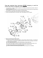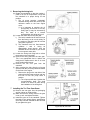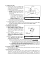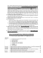
1
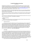
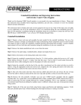
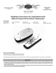
TRU-TIME
CAM
GEARS
Mitsubishi 1995-2001 Eclipse 2.4L SOHC
Part Number 23-852
,!
WARNING:
This installation is not for the mechanically challenged! If you
are not mechanically inclined or do not understand the
procedure please do not attempt the installation. Refer the
installation to a reputable mechanic. It is highly recommended to
purchase the factory service manual to use as a guide along with
these instruction sheets.
Legal in California ONLY for racing vehicles, which may never be used upon a highway.
ADVANCED ENGINE MANAGEMENT INC.
2205 126th. St. Unit A
Hawthorne, CA 90250
(310) 484-2322
Http://www.aempower.com
Instruction part # 10-261
© Copyright 2001
You have just purchased the BEST adjustable cam sprockets available. These AEM
Inc. billet aluminum adjustable cam sprockets are CNC machined from billet aluminum
and then laser etched with cam timing marks for adjustment up to ±10° at the cam or
±20° at the crankshaft. Using the vernier scale on the sprocket hub helps to do the cam
timing changes quickly and accurately. The inner hub is anodized for lasting beauty and
resistance to corrosion. The out gear sector is hard anodized for resistance to wear.
We have found that there are significant power gains to be made by adjusting the cam
timing even with stock cams and compression. Adjustable cam sprockets are usually
required in applications where an aftermarket or reground performance cams are
installed or the cylinder head has been milled 0.005” or more. The use of these cam
sprockets allows the extraction of maximum power from your engine. We have recorded
gains of up to 10~15 horsepower due to cam timing tuning using adjustable cam
sprockets.
When an aftermarket or reground cam is installed, the original manufacturer’s cam
timing specifications are no longer accurate. The adjustable cam sprocket allows you to
make necessary adjustments to cam timing to maximize the performance of your
engine. This is accomplished by “degreeing in” the optimum cam timing for a particular
engine set up.
The adjustable cam sprocket is especially effective when used with heads that have
been milled. The adjustability of the sprocket allows the accommodation of the changes
in cam timing due to the variation of timing belt length from the bottom sprocket to the
top sprocket when the head is milled. If the head has been milled 0.005” or greater the
relationship between the head and the block is altered by moving the head closer to the
crankshaft resulting in retarded cam timing.
It must be emphasized that the preceding descriptions are generalizations and any
adjustments made must be done with a conservative approach and on a dynamometer
or on a racetrack. We do not condone any illegal activity on the street.
The AEM Billet Aluminum Cam Sprockets are available for:
Read and understand these instructions BEFORE attempting to install this
product. See reference to diagrams on back page.
1. The procedure to change the gears is identical to the timing belt replacement procedure outlined in
the factory service manual.
2. Obtain a suitable box or container to hold the hardware that will be removed from the engine during
this installation. This will aid in the prevention of lost nuts and bolts.
3. Disconnect the negative battery terminal before starting these procedures.
4. Remove the Spark plugs from the vehicle to aid in the installation of the cam gears.
5. Removal of timing belt front covers
(a) Raise the front of the vehicle and support it using properly rated jack stands. It is important for
safety reasons to use adequate supporting equipment to prevent injury or damage to the vehicle.
(b) Remove the front right wheel.
(c) From underneath vehicle, remove inner debris shield from inside fender well.
(d) Put a jack underneath the engine for support and remove the front & driver side engine mount.
(e) Remove all drive belts (a/c, oil pump, power steering and the alternator belts).
(f) Remove the water pump pulley and crankshaft pulley.
(g) Remove the front lower cover timing belt upper and lower timing belt cover assembly.
6. Removing the timing belt
(a) Rotate the crankshaft so that the number 1
piston is at TDC on compression. Verify that
the camshaft is in proper timing for this
position.
i) The oil pump sprocket, crankshaft,
camshaft timing marks are lined up with
reference marks on the front engine
cover.
(1) It is important to examine the oil
pump pulley as the mark is not very
easily seen (it may be obscured by
dirt). The mark is a reverse
embossed dot with white paint on it.
(b) Loosen the center bolt on the cam gear.
i) The bolt is installed at 65 ft-lbs of torque
from the factory so do not rely solely on
the tension of the timing belt to hold the
cam gears in position.
ii) The camshaft have hex flats between
cylinders 1 and 2. Using an
appropriately sized wrench, hold the
camshaft at the hex flats as you loosen
the cam gear’s center bolt.
(c) Loosen the timing belt fixing bolt to relieve
the tension on the timing belt.
(d) Remove the timing belt from the cam gear.
This is an appropriate time to replace the
timing belt if replacement is due or is close
to the replacement interval.
(e) Remove the OE cam gear from the
camshaft.
(f) After removing the belt, align the oil pump
sprocket with the previously identified marks
on the front of the engine.
i) Remove the plug on the rear side of the
engine block and insert an 8mm rod into
the hole to lock the pump shaft in
position.
(1) The oil pump shaft also includes the
counter-balance shaft. This shaft
needs to be locked in place during
the installation of the timing belt.
7. Installing the Tru-Time Cam Gears.
(a) Remove the cam gear from the packaging
and lay it down on a flat surface.
(b) Make sure that the timing mark on the gear
is set up at 0° and tighten the bolts.
(c) Install the gear on to the camshaft. Tighten
the bolts to the proper factory specification
(65 ft-lbs) Hold the camshaft at the hex flats
as you tighten the gear.
Figure 2A, 2B, 2C & 2D
8. Installing timing belt
(a) Install the timing belt on the camshaft. Make
sure that the gear is at the proper position with
the pin straight up and the alignment marks are
horizontal timing belt tensioner
i) From beneath, remove the automatic belt
tensioner.
ii) On a vise, compress the tensioner until the
hole in the shaft aligns with the hole in the
tensioner body.
(1) This procedure should be done over a
15-minute period to allow the tensioner
to bleed down. If you compress the
tensioner down too fast you may
Figure 3
damage it internally (please see the
factory service manual).
iii) Once the tensioner has been compressed and the holes are aligned, insert the 1/16th-inch pin
into the holes to lock the tensioner in place.
(b) Complete installing the belt on to the lower pulleys.
i) Ensure that all the timing marks are in their proper position after the belt is installed. Any
deviation from these procedures can lead to serious engine damage.
(c) Install the timing belt tensioner.
9. Resetting the tension pulley
(a) Install the automatic tensioner in place.
(b) With a suitable tool rotate the tension-pulley
counter clockwise and apply 3 ft-lbs to the
center eccentric while tightening the fixing bolt.
Do not allow the eccentric to rotate with the
center bolt as you tighten it (refer to factory
service manual).
(c) Let the automatic tensioner to sit for 15
minutes then measure the amount of
protrusion of the auto tensioner. It should be
3.8-4.5 mm, if not repeat the pulley adjustment
procedures.
(d) Tighten the adjustment bolt of the cam gear to
15 ft-lbs. Remove the lock pin for the oil
Figure 4
pump shaft described step 5f.
i)
Rotate the crankshaft by hand in the normal direction of engine rotation at the crankshaft.
(1) Do this several times and make sure you do not feel any resistance to rotation.
(a) The crankshaft should rotate freely with the spark plugs removed. If resistance is
encountered check to see that the timing marks on all the pulleys line up when the
crankshaft is at TDC and/or that the oil pump shaft is not locked.
(2) Check the timing marks for both the camshaft and crankshaft with each revolution and
that the oil pump shaft marks line up every third revolution. Failure to ensure that engine
is in proper time will result in engine damage.
10. Assembly of engine components
(a) Once the timing belt is installed and cam timing verified the assembly of the motor is the reverse
of the procedures just outlined.
11. Cam timing adjustment procedures
(a) The performance of an aftermarket cam can be optimized by using the AEM cams gears by
“degreeing in” the proper cam timing for your particular engine set up. This procedure is best
carried out on a dynamometer so that quantifiable results can be measured. The advancing or
retardation of cam timing will affect the peak power of the engine by moving the power band up or
down. Usually, advancing the cam gives more low-end power and, conversely, retarding the cam
timing gives a higher peak rpm and power. We must emphasize that this is only a generalization
and that you must perform dyno/track testing to fully realize the benefit of these sprockets. In the
absence of a dyno, timed acceleration tests can be performed. (We do NOT condone illegal
activity on the street and STRONGLY recommend the timed acceleration tests be
carried out at a racetrack.) The method we use to perform the timed tests is to start at a
(b)
(c)
(d)
(e)
(f)
constant engine RPM in second gear (both for manual and automatic transmission) and then
accelerate to the vehicle redline while recording the time it takes to reach redline. We perform this
test at least 3 times to establish an average reference point. Notice that there is no shifting or tire
burning (if you do have a traction problem, use a higher gear) in this procedure. Using this
procedure will give reliable and repeatable data.
As outlined at the preface of these instructions adjustments to the cam timing must be done with
a very conservative approach. Excessive movement of the cams during adjustment increases the
likelihood that the pistons and valves will touch.
All testing should be done on a chassis dynamometer or at the test track. Under no circumstance
should you resort to testing on public roads.
Check ignition timing.
i) Verify that the ignition timing is correct (use a timing light to do this, do not guess). The
ignition timing must be verified EACH time the cam timing is changed because the cam
drives the distributor. Any change to the cam timing will affect the ignition timing.
ii) To change the cam timing, loosen the three retaining bolts (figure 1) in the slotted holes in the
inner hub. Rotate the cam to the desired position and retighten the three retaining bolts to 15ft. lbs. If the head is milled, then retarding the exhaust cam lobe timing must be carried out
with extreme care. You must have at least .060” between the piston and the valve.
After the cam timing change is made, reset your ignition timing and go out and try your
acceleration test or perform dyno testing. You must check your fuel calibration after each cam
timing change in order to perform an accurate test. The cam timing has a profound effect of the
air/fuel mixture and if it is not optimized for each cam timing setting you will not know if the effect
of the change in cam timing is positive or negative.
When you have concluded testing, re check the cam bolts for tightness, apply Loctite® “red”
to the three retaining bolts, re install the cam belt cover and know that you have installed the
best cam timing sprocket available.
Caution: Cam adjusting bolts loose. Tighten before starting engine.
For Technical Inquiries please E-Mail us at [email protected]
Reference
Figure 1
Figure 2A
Figure 2B
Figure 2C
Figure 2D
Figure 3
Figure 4
1. Drive Belt (Power steering, Oil Pump and A/C)
2. Drive Belt (Alternator)
3. Water Pump Pulley
4. Crank Shaft Pulley
5. Timing Belt Upper Cover Assembly
6. Timing Belt Lower Cover Assembly
7. Timing Belt
8. Tensioner Pulley
9. Auto Tensioner
Diagram showing the relationship of the pulleys when cylinder no. 1 is at TDC on compression.
Diagram showing the location of the timing belt tensioner fixing bolt.
Diagram showing the location of all timing marks at TDC.
Diagram showing the location of the plug on the rear side of the engine block. Secondary
diagram shows the balance shaft in its proper position.
Diagram showing how the lock-pin is to be inserted into the automatic tensioner.
Diagram showing how to measure the protrusion of the automatic tensioner.