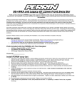
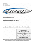
1
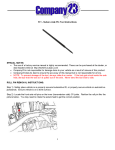
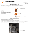
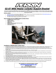
KINGPIN REPLACEMENT
INTRODUCTION
Author: Randy Baumann
All information, illustrations and specifications are based
on the best information available at the time of publication.
The author cannot guarantee the accuracy of the
information contained in this publication. Corrections are
welcomed, and can be submitted to [email protected].
Information included in this publication comes from a variety
of sources, that include, but are not limited to the following:
Chevrolet Shop Manual, 1942—1948 Passenger Cars and
1942—1946 Trucks©
This information is provided to assist fellow hobbyists in
the restoration and maintenance of their Chevrolet™ trucks.
Additional Contributors:
NOTE: The following procedure documents a typical
kingpin replacement. The details of your application
will vary. Always refer to the service manual that
matches to year, make and model of your vehicle
for the correct procedure.
The kingpins and bushings are important parts of the
steering system. Regular maintenance and inspection are
necessary to ensure safety operation.
1/2- and 3/4-ton trucks use bronze “floating” kingpin
bushings that do not require reaming. These bushing are
manufactured to final size.
1-1/2-ton conventional trucks and school buses use spindle
bushings that are press-fit into the spindles, and require
reaming to the final size.
Dave Feltner “Koolkar”
Stuart Miller “atomarc”
Chevrolet™ is a registered trademark of the Chevrolet Motor Division of the General Motors Corporation.
05/January/2007
Page 1
Revision C
TECH TIP
COMPONENT IDENTIFICATION
A460195A
Figure 1: Spindle Assembly Cross Section View—Driver’s Side, Viewed from Rear
A—Dust Cap
L—Stop Bracket
B—Nut
M—Steering Arm
C—Outer Bearing
N—Axle
D—Spindle
O—Tie Rod
E—Hub
P—Tie Rod End
F—Inner Bearing
Q—Kingpin
G—Brake Drum
R—Brake Shoe
H—Wheel Cylinder
S—Bearing
I—Backing Plate
T—Seal
J—Grease Fitting (3 Used)
U—Washer
K—Lock Pin
05/January/2007
Page 2
Revision C
TECH TIP
REMOVAL
The following procedures document a typical kingpin
application for 1/2- and 3/4-ton trucks. The procedure for
1-1/2-ton truck and school buses are similar.
WARNING!
SUPPORT THE VEHICLE SECURELY!
Place jackstands under the frame rails. Never work
under or near a vehicle supported only by a jack or
other lifting device. Failure to properly support the
vehicle and components may result in death or
serious injury.
1. Lift the vehicle until both wheels are off the ground.
Place jackstands under the frame rails behind the
springs.
A460123B
Figure 3: Remove Locking Bolt
2. Remove the wheels and tires.
3. Remove the brake components and backing plates, and
steering arms.
CAUTION
DO NOT use heat to remove the kingpin. Heat may
weaken or distort the spindle and axle.
5. See Figure 3. Remove the nut (D), lock washer (E),
stop bracket (F) and kingpin locking bolt (G).
NOTE: If the kingpin cannot be driven out, remove the
axle from the vehicle and use a press to remove
the kingpin.
6. Drive the kingpin (H) out using a hammer and soft brass
punch.
A460121B
Figure 2: Remove Retaining Rings and Dust Caps
4. See Figure 2. Remove the top and bottom retaining
rings (A) and dust caps (B) from spindle (C).
05/January/2007
Page 3
Revision C
TECH TIP
A460124B
Figure 4: Remove Spindle
A460126B
IMPORTANT
Figure 5: Remove Spindle Bushings
Record the location and number of shims used (if any) to
ensure proper assembly.
7. See Figure 4. Remove the spindle (C), thrust bearing
(I) and shim (J) (if any) from the axle (K).
IMPORTANT
Use caution when removing bushings, DO NOT damage
the bushing bore.
8. See Figure 5. Remove the bushings (L) from the spindle
(C) using a soft brass punch.
9. Remove the grease fittings (M).
05/January/2007
Page 4
Revision C
TECH TIP
INSPECTION
A460204A
Figure 6: Inspect the Spindle Assembly
A460205A
CAUTION
Figure 7: Inspect Axle Bore
DO NOT use sandpaper or abrasives to clean the
spindle and axle bores. The use of abrasives will
remove excessive material, causing a loose kingpin
fit and premature wear.
3. See Figure 7. Inspect the axle kingpin bore (B). The
bores should be free of pitting, rust, scoring, cracks, or
worn out-of-round. Replace the axle if any damage is
noted.
Apply anti-seize compound to the axle kingpin bore (B),
and insert the new (replacement) king pin (C), into the
axle to check the fit. The king pin should be a hard
hand-push fit, and should not have any play.
1. See Figure 6. Thoroughly clean and inspect the spindle
assembly. Replace the spindle if any damage is noted.
2. Inspect the spindle kingpin bushing bores (A). The bores
should be free of pitting, rust, scoring or cracks. Light
rust or pitts can be removed using a brake hone. Replace
the spindle(s) as needed.
If any play is noted, an oversize kingpins and bushings
must be used, and the axle bore must be reamed to fit
the new king pin.
NOTE: If proper equipment is available, the axle may be
reamed while the axle is still installed on the vehicle.
If not, remove the axle, and have a have it reamed
to match the oversize kingpin at a machine shop.
05/January/2007
Page 5
Revision C
TECH TIP
INSTALLATION
WARNING!
SUPPORT THE VEHICLE SECURELY!
Place jackstands under the frame rails. Never work
under or near a vehicle supported only by a jack or
other lifting device. Failure to properly support the
vehicle and components may result in death or
serious injury.
A460124C
Figure 9: Install the Spindle and Thrust Bearing
NOTE: Install the thrust bearing with the dust shield up
(toward the axle).
3. See Figure 9. Install the spindle (B) and thrust bearing
(E) on the axle (G). Check the clearance between the
spindle and axle. If the clearance is greater than 0.006”,
install a shim (F)
A460126C
Figure 8: Install Spindle Bushings
IMPORTANT!
When installing the bushings, it is important that the grease
channels are aligned with the grease fittings. Installing
the bushing incorrectly will result in premature kingpin and
bushing wear.
1. See Figure 8. Install new grease fittings (A) into spindle
(B).
2. Apply a light coat of wheel bearing grease to the new
bushings (C), and install bushings, aligning the grease
channels (D) in the bushing with the grease fittings (A).
A460123C
Figure 10: Install the Kingpin
4. See Figure 10. Install the kingpin (H), aligning the notch
(I) in the kingpin with the lock pin hole (J) in the axle.
5. Install the lock pin (K), stop bracket (L), lock washer
(M) and nut (N).
05/January/2007
Page 6
Revision C
TECH TIP
A460121C
Figure 11: Install Dust Caps and Retaining Rings
6. See Figure 11. Install dust caps (O) and retaining rings
(P).
NOTE: Tighten spindle nut to specifications. Always use
a new cotter pin when installing the spindle nut.
7. Install backing plates, brake components, and steering
arms.
8. Apply grease to grease fittings. Grease spindle bushings
regularly to ensure long bushing life.
9. Perform front end alignment.
05/January/2007
Page 7
Revision C