1
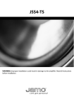
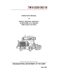
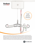
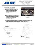
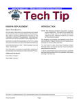
SERVICE
BULLETIN
NUMBER:
DATE:
MODEL:
SB-422-004
8/27/02
All with
MACK Front
Axles
(Also applies to Mack Trucks Australia)
(Supersedes bulletin SB-422-004 dated 2/6/98)
KINGPIN LATERAL PLAY MEASUREMENTS, STEERING KNUCKLE
VERTICAL CLEARANCE MEASUREMENTS AND ADJUSTMENTS,
AND KINGPIN LUBRICATION PROCEDURES
MACK Front Axle Models FA(W) 10.5, 12, 14.3, 16, 18 and 20
Kingpin Lateral Play Measurements
Before replacing kingpins, bushings/bearings on a MACK front axle, kingpin lateral play
must first be checked with a dial indicator to verify replacement of these components is
actually necessary. Kingpins, bushings and bearings should be replaced only when lateral
play exceeds 0.015″ (0.381 mm). Procedures for measuring kingpin lateral play are as
follows:
1. Place blocks at the rear wheels to prevent the vehicle from moving.
2. Raise the front of the vehicle off the ground and support on jack stands of adequate
capacity.
Do not work under a vehicle that is supported only on a
hydraulic jack, as a hydraulic jack could fail suddenly and
unexpectedly, resulting in severe personal injury or death.
Always use jack stands of adequate capacity to support the
weight of the vehicle.
3. Measure kingpin lateral play at the upper bearing as follows:
a.
Secure the dial indicator base to a flat portion at the top of the axle beam as
shown in the illustration in Figure 1.
For the most accurate measurements, mount the dial indicator
on a surface of the axle beam that is as flat as possible.
SB-422-004 — Page 1 of 6
SERVICE PUBLICATIONS, ALLENTOWN, PA 18105
©MACK TRUCKS, INC. 2002
1
Figure 1 — Measuring Kingpin Upper Bearing Lateral Play
b.
Position the dial indicator tip against the upper portion of the steering knuckle as
shown in the illustration above.
c.
Zero the dial indicator.
d.
Rotate the wheel so that a hand hole (steel or aluminum disc wheels), or space
between spokes (spoke wheel) is in the twelve o'clock position. Insert a pry bar
through the hand hole (or the space between spokes) and position on the top of
the brake drum. Pull the pry bar upward to move the wheel assembly and knuckle
while observing the reading on the dial indicator. Use care to prevent damaging or
marring the wheel surface with the pry bar.
To assure accurate measurements, do not allow the steering
knuckle to turn to the left or right while moving the tire/wheel
assembly. Having an assistant apply the brakes will lock the
wheel in position and aid in preventing the steering knuckle from
turning.
A reading of greater than 0.015″ (0.381 mm) on the dial indicator indicates that the
upper bearing is worn or damaged. Overhaul the steering knuckle with the appropriate
kingpin rebuilt kit.
SB-422-004 — Page 2 of 6
4. Measure kingpin lateral play at the lower bushing as follows:
a. Secure the dial indicator base to a flat portion at the bottom of the axle beam as
shown in the illustration below (Figure 2).
For the most accurate measurements, mount the dial indicator
on a surface of the axle beam that is as flat as possible.
2
Figure 2 — Measuring King Pin Lower Bushing Lateral Play
b.
c.
d.
Position the dial indicator tip against the lower portion of the steering knuckle as
shown in Figure 2.
Zero the dial indicator.
Rotate the wheel so that a hand hole (steel or aluminum disc wheels), or space
between spokes (spoke wheel), is in the twelve o'clock position. Insert a pry bar
through the hand hole (or the space between spokes) and position on top of the
brake drum. Pull the pry bar upward to move the wheel assembly and knuckle
while observing the reading on the dial indicator. Use care to prevent damaging or
marring the wheel surface with the pry bar.
To assure accurate measurements, do not allow the steering
knuckle to turn to the left or right while moving the tire/wheel
assembly. Having an assistant apply the brakes will lock the
wheel in position and aid in preventing the steering knuckle from
turning.
A reading of greater than 0.015″ (0.381 mm) on the dial indicator indicates that the
lower bushing is worn or damaged. Overhaul the knuckle assembly with the
appropriate kingpin rebuild kit.
SB-422-004 — Page 3 of 6
Steering Knuckle Vertical Clearance Measurement and Adjustment
REV
Steering knuckle vertical clearance must be checked and adjusted if necessary, at the first A
inspection when the chassis is new, and thereafter, at each C and D inspection. Clearance
between the knuckle and the top of the axle eyelet should be set between 0.005″–0.027″
(0.127–0.686 mm) to provide a minimum clearance of 0.020″ (0.508 mm) between the
knuckle and the bottom of the axle eyelet. Failure to maintain this clearance may result in
accelerated wear of the steering knuckle/axle beam assembly.
Steering knuckle vertical clearance must be measured with the
vehicle on the ground, or if the front of the vehicle is raised, with
a jack placed under the steering knuckle as shown in Figure 3, to
load the knuckle upward.
3
Figure 3 — Using Jack to Load Knuckle Upward
SB-422-004 — Page 4 of 6
To measure the clearance, place a thickness gauge between the steering knuckle and the
axle beam eyelet as shown in Figure 4. Measure at three locations, approximately 90
degrees apart, around the axle beam eyelet.
4
Figure 4 — Measuring Upper Clearance
REV
If the measurement is not between 0.005″–0.027″ (0.127–0.686 mm), adjust vertical
clearance as follows:
1. Place blocks under the rear wheels to prevent the vehicle from moving.
2. Raise the front of the vehicle off the ground and support on jack stands of adequate
capacity.
Do not work under a vehicle that is supported only on a
hydraulic jack, as a hydraulic jack could fail suddenly and
unexpectedly, resulting in severe personal injury or death.
Always use jack stands of adequate capacity to support the
weight of the vehicle.
3. At the bottom of the steering knuckle, remove the cotter pin that secures the adjusting
screw.
4. Turn the adjusting screw clockwise to draw the knuckle snug against the top of the axle
beam eyelet.
5. Once the knuckle is snug against the axle beam, turn the adjusting screw
counterclockwise until the first cotter pin slot aligns with the cotter pin hole. Recheck
the vertical clearance as described previously. If upper clearance is not within range,
turn the adjusting nut an additional 1/4 turn counterclockwise until the second cotter pin
slots align with the cotter pin hole. Recheck the measurement.
6. After proper steering knuckle upper clearance has been set, install a new cotter pin to
secure the adjusting nut in place.
SB-422-004 — Page 5 of 6
REV
When the steering knuckle upper clearance is properly set between 0.005″–0.027″ (0.127–
0.686 mm), verify that the lower clearance is at least 0.020″ (0.508 mm) by measuring the
gap between the steering knuckle and the bottom of the axle beam eyelet with a thickness
gauge as shown in Figure 5.
5
Figure 5 — Measuring Lower Clearance
If proper vertical clearance cannot be obtained, the steering knuckle must be overhauled.
Refer to the Front Axle and Steering System Service Manual, 12–101 for overhaul
procedures.
King Pin Lubrication Procedures
Lubricate the king pin upper bearing with the vehicle on the ground. Apply the
recommended chassis lubricant to the upper bearing grease fitting until grease purges from
the joint between the upper steering knuckle and the upper portion of the axle eyelet.
Lubricate the king pin lower bushing with the front of the vehicle raised off the
ground and supported on jack stands of adequate capacity. This ensures that grease
will completely fill the areas around the king pin and bushing. Apply the recommended
chassis lubricant to the lower bushing grease fitting until grease purges from the joint
between the lower steering knuckle and the lower portion of the axle eyelet.
Do not work under a vehicle that is supported only on a
hydraulic jack, as a hydraulic jack could fail suddenly and
unexpectedly, resulting in severe personal injury or death.
Always use jack stands of adequate capacity to support the
weight of the vehicle.
Refer to the Maintenance and Lubrication Manual, TS494, for additional information
concerning chassis vocation, and other lubrication recommendations and requirements.
SB-422-004 — Page 6 of 6