1
Service Manual
AVL OMNI 1-9
Modular System
CH3496
Rev. 9.0, May 2000
Ma nufactured by:
AVL LIST GmbH MEDIZINTECHNIK
Hans-List-Platz 1
8020 Graz / Austria
Distributed by:
AVL MEDICAL INSTRUMENTS AG
Stettemerstraße 28
8207 Schaffhausen / Switzerland
AVL MEDIZINTECHNIK GMBH
Norsk-Data-Straße 1
Postfach 1142
61281 Bad Homburg / Germany
AVL LIST GMBH MEDIZINTECHNIK
Hans-List-Platz 1
8020 Graz / Austria
AVL SCIENTIFIC CORPORATION
Roswell, Georgia 30076 / USA
Local AVL representative:
Copyright 2000 AVL List GmbH, all rights reserved
The contents of this document may not be reproduced in any form or communicated to any third party without the prior
written consent of AVL. While every effort is made to ensure its correctness, AVL assumes no responsibility for errors
or omissions which may occur in this document. Subject to change without notice.
First Edition: June 1995
- Important Information! - Important Information! -
This Service Manual contains important warnings and safety instructions to be observed by the user.
This instrument is only intended for one area of application which is described in the instructions. The most important
prerequisites for application, operation and safety, are explained to ensure smooth operation. No warranty or liability
claims will be covered if the instrument is applied in areas other than those described or if the necessary prerequisites
and safety measures are not observed.
The instrument is only to be operated by qualified personnel capable of observing these prerequisites.
Only accessories and supplies either delivered by or approved by AVL are to be used with the instrument.
Due to this instrument operating principle, analytical accuracy not only depends on correct operation and function, but
also upon a variety of external influences beyond manufacturers control. Therefore the test results from this instrument
must be carefully examined by an expert, before further measures are taken based on the analytical results.
Instrument adjustment and maintenance with removed covers and connected power, are only to be performed by a
qualified technician who is aware of the dangers involved.
Instrument repairs are only to be performed by the manufacturer or qualified service personnel.
Explanation:
!
This symbol is located on the inside of the instrument:
"Refer to the Operator’s Manual / Service Manuals".
Symbol for instrument type B:
An instrument of the B-type falls under safety categories I, II or III, or has an internal power supply,
providing the required insulation against discharge current and reliable ground connections.
- Important Information! - Important Information! -
- Operating Safety Information ∗ The instrument falls under Safety Category I.
∗ The instrument belongs to Type B.
∗ The instrument is designed as a conventional device (of closed, not waterproof type).
∗ Do not operate the instrument in an explosive environment or in the vicinity of explosive
anesthetic mixtures containing oxygen or nitrous oxide.
∗ The instrument is suitable for continous operation.
CAUTION:
• The power cord may be plugged only into a grounded socket. When using an extension cord, make sure it is properly
grounded.
• Any rupture of the ground lead inside or outside the instrument or a loose ground connection can render hazardous
operation of the instrument. Intentional disconnection of the grounding is not permitted.
• While changing the fuses, make sure that the fuses used, are of the specified type and rating in
every case. Never use repaired fuses or short-circuit the fuse holders.
- Operating Safety Information -
Contents
Contents
1 INTRODUCTION
General information............................................................................................................................ 1-1
Important information ........................................................................................................................ 1-1
Warnings............................................................................................................................................. 1-2
ESD protective measures..................................................................................................................... 1-3
Device leakage current measurements - Testing after field repair and modifications ......................... 1-5
Decontamination/Cleaning .................................................................................................................. 1-6
2 REVISIONS
Elektronic ........................................................................................................................................... 2-1
Software .............................................................................................................................................. 2-3
Service Manual ................................................................................................................................... 2-6
3 DESCRIPTION OF FUNCTIONS / SPECIFICATIONS
Application ......................................................................................................................................... 3-1
Measurement parameters .................................................................................................................... 3-7
Input values ........................................................................................................................................ 3-8
Calculated parameters ........................................................................................................................ 3-9
Type of calibrations .......................................................................................................................... 3-10
Type of measurements....................................................................................................................... 3-10
Sample dates / calibration times........................................................................................................ 3-11
Sample volumes ................................................................................................................................. 3-12
Type of anticoagulants ...................................................................................................................... 3-12
Reagents............................................................................................................................................ 3-13
Measurement data............................................................................................................................. 3-17
Service Manual, AVL OMNI, Rev. 9.0, May 2000
I
Contents
Environmental considerations – Instrument ...................................................................................... 3-17
Environmental considerations - Electrodes........................................................................................3-18
Environmental considerations - Reagents ..........................................................................................3-18
Electrical requirements .....................................................................................................................3-18
Data management ..............................................................................................................................3-19
Classification .....................................................................................................................................3-19
Dimensions.........................................................................................................................................3-19
Weight ...............................................................................................................................................3-19
Test certificates .................................................................................................................................3-20
Acoustic noise level ............................................................................................................................3-20
4 INSTALLATION / SHUTDOWN
Installation ..........................................................................................................................................4-1
Shutdown procedure ..........................................................................................................................4-11
Installation of the AutoQC module (option) ......................................................................................4-14
Options ..............................................................................................................................................4-18
5 FUNCTION MODULES FROM A - Z
General information on assembly and disassembly of components ......................................................5-1
Aerosol trap (applicable from SN 5000 on) ..........................................................................................5-3
AutoQC module (optional) ...................................................................................................................5-4
Bacteria filter ....................................................................................................................................5-24
Barcode control .................................................................................................................................5-24
Barcode scanner (optional) ................................................................................................................5-25
Bypass cartridge ................................................................................................................................5-27
Changing the cable trees, flat cables, single cables and optical light guides ......................................5-28
Container pipes..................................................................................................................................5-29
Fan and Filter ....................................................................................................................................5-30
II
Service Manual, AVL OMNI, Rev. 9.0, May 2000
Contents
Fill level sensors - Waste cap with fill level detection ....................................................................... 5-31
Fluid mixing system (FMS) ............................................................................................................... 5-41
Hemolyzer (applicable from SN 5000 on; for SN < 5000, see chapter 10, Manual revision 8.0) ........ 5-43
Mainboard ........................................................................................................................................ 5-45
Measuring chambers ......................................................................................................................... 5-49
Motherboard ..................................................................................................................................... 5-95
Power supply unit ............................................................................................................................. 5-97
PC components (applicable from SN 1500 on; for SN < 1500, see chapter 10, Manual revision 3.0) . 5-98
Peristaltic pump (PP) .......................................................................................................................5-115
Pre-filter ..........................................................................................................................................5-119
Sample distributor (SD) ...................................................................................................................5-120
Thermal printer ...............................................................................................................................5-128
T&D system......................................................................................................................................5-130
Vacuum pump ..................................................................................................................................5-138
Vacuum sensor .................................................................................................................................5-140
Valves (applicable from SN 5000 on; for SN < 5000, see chapter 10, Manual revision 8.0)..............5-141
Figures .............................................................................................................................................5-158
6 SYSTEM FUNCTIONS
General view ....................................................................................................................................... 6-1
Test ..................................................................................................................................................... 6-2
Setup ................................................................................................................................................... 6-4
Calibration / Util................................................................................................................................. 6-6
QC-measurement - Data manager - Options ....................................................................................... 6-8
Service Manual, AVL OMNI, Rev. 9.0, May 2000
III
Contents
7 FUNCTIONAL PROCEDURES
Calibration cycle..................................................................................................................................7-1
Measuring cycle ...................................................................................................................................7-6
MSS polarization ...............................................................................................................................7-13
MSS Ref. calibration (AVL OMNI 7 to 9) .........................................................................................7-19
MSS Int/1P/Slp calibration (AVL OMNI 7 to 9) ................................................................................7-21
Phases of diverse AVL OMNI actions .............................................................................................7-23
Tubing diagrams ................................................................................................................................7-27
8 MAINTENANCE / SERVICE AREA
Maintenance ........................................................................................................................................8-1
Software update ...................................................................................................................................8-7
Service area .........................................................................................................................................8-8
9 TROUBLESHOOTING
Errors identified by the software.........................................................................................................9-1
Error functions not identified by the software ..................................................................................9-53
Service report ....................................................................................................................................9-84
10 PREVIOUS REVISION LEVELS
Manual revision 2.0, December 1995 .................................................................................................10-2
Manual revision 3.0, March 1996 ......................................................................................................10-3
Manual revision 4.0, July 1996 ........................................................................................................ 10-25
Manual revision 5.0, January 1997 .................................................................................................. 10-29
Manual revision 6.0, August 1997 .................................................................................................... 10-33
IV
Service Manual, AVL OMNI, Rev. 9.0, May 2000
Contents
Manual revision 7.0, May 1998 ........................................................................................................10-45
Manual revision 8.0, November 1998 ...............................................................................................10-49
Manual revision 9.0, May 2000 ........................................................................................................10-79
INDEX
Service Manual, AVL OMNI, Rev. 9.0, May 2000
V
Contents
VI
Service Manual, AVL OMNI, Rev. 9.0, May 2000
•, ∆
∆
SR ≥5.50
9.0, May 00/
2.0, Dec. 95/
SN 1146
3.0, March 96/
SN 1500
Modification (previous states of revision see chapter 10, "Previous revision levels")
New or addition !
Service Manual, AVL OMNI, Rev. 9.0, May 2000
•
∆
General information
Important information
Warnings
ESD protective measures
Device leakage current measurements Testing after field repair and modifications
Decontamination
Manual revision/
applicable from serial number (SN) or
software revision number (SR)
General information
Important information
Warnings
ESD protective measures
Device leakage current measurements Testing after field repair and modifications
Decontamination
Manual revision/
applicable from serial number (SN) or
software revision number (SR)
∆
SR ≥3.0
SR ≥2.0
∆
5.0, Jan. 97/
4.0, July 96/
List of modifications, chapter 1 (Introduction)
•, ∆
•, ∆
SR ≥4.0
6.0, August 97/
∆
∆
SR ≥4.5
7.0, May 98/
1
∆
8.0, Nov. 98/
SN 5000
SR ≥5.0
Service Manual, AVL OMNI, Rev. 9.0, May 2000
2
1 Introduction
1 INTRODUCTION
General information............................................................................................................................ 1-1
Important information ........................................................................................................................ 1-1
Warnings............................................................................................................................................. 1-2
ESD protective measures.....................................................................................................................
Explanation of the Phenomenon .........................................................................................................
Impact of static electricity on assemblies ............................................................................................
Why is ESD protection so important today .........................................................................................
How can ESD protection be ensured? .................................................................................................
Conclusion ........................................................................................................................................
1-3
1-3
1-3
1-3
1-4
1-4
Device leakage current measurements - Testing after field repair and modifications ......................... 1-5
Decontamination/Cleaning .................................................................................................................. 1-6
Disinfectants ..................................................................................................................................... 1-6
AVL Deproteinizer......................................................................................................................... 1-6
Commercial disinfectant ................................................................................................................. 1-7
Decontamination ............................................................................................................................... 1-7
Sample drip tray............................................................................................................................. 1-7
Fill port ......................................................................................................................................... 1-7
T&D disk....................................................................................................................................... 1-8
Touch screen ................................................................................................................................. 1-9
Surfaces......................................................................................................................................... 1-9
MSS tubes ....................................................................................................................................1-10
Electrodes / Measuring Chamber....................................................................................................1-10
Service Manual, AVL OMNI, Rev. 9.0, May 2000
1-I
1 Introduction
1 Introduction
General information
This Service Manual includes all information and data necessary for repair and
maintenance of the AVL OMNI.
In order to fully understand the described procedures in this manual, it is
necessary to be familiar with the manner of function and handling of the
analyzer. This information can be obtained from the Operator’s Manual.
Proper functioning of the AVL OMNI can only be ensured when maintenance
and repairs are performed, according to the procedures described in this
Service Manual. The use of original AVL parts and suggested materials is also
necessary.
The order numbers of spare parts are located in the spare part list.
Chapter 2 of this Manual includes a summary of all mechanical or electronic
modifications, as well as available software versions.
Important information
Information in this manual marked "NOTE", describes situations or hazards
which can damage or cause malfunctioning of the analyzer.
• Use a stable, level working environment (max. ± 1 degree inclination when
bottles are inserted).
• Prevent vibrations, direct sunlight and strong electromagnetic fields
(Electro motors, transformers, x-ray devices, immediate vicinity of mobile
telephones e.g.).
• Allow approx. 10 cm space around the analyzer for air circulation and
electrical supply.
• Ambient temperature: +15 °C to + 31 °C
• Relative humidity:
AVL OMNI 1 - 6, up to 95 %
AVL
up to
up to
up to
up to
OMNI 7, 8, 9:
70 %, if temp. < 31
83 %, if temp. < 28
90 %, if temp. < 27
95 %, if temp. < 31
°C,
°C,
°C,
°C,
(MC
(MC
(MC
(MC
Temp.
Temp.
Temp.
Temp.
25
25
25
30
°C)
°C)
°C)
°C)
• The power supply must be between 100 - 240 V AC (+6%/-10% permissible
tolerance). No setting is necessary.
• Avoid leakage of fluids inside the analyzer. This can lead to damage in the
electronics.
• Only use damp tissue or cotton swabs to clean the analyzer.
• Complete service and repair tasks as described in this manual. Improper
service and repairs can result in loss of warranty rights.
Service Manual, AVL OMNI, Rev. 9.0, May 2000
1-1
1 Introduction
• Only use proper tools and test facilities for service and repairs.
• Replace damaged fuses with approved or original types only.
•
Electrostatic Sensitive Device
Packages with this label should be opened by qualified
personnel only.
Warnings
Warnings in this Manual are marked with "CAUTION" and describes
situations or potential dangers which can be hazardous for persons doing
maintenance or service tasks.
• Never use the analyzer near easily inflammable or explosive gases
(e.g. anaesthesic gases etc.).
• Always connect the analyzer to a grounded 2-pole socket.
• Replace immediately a damaged power plug or cable.
• Before opening the rear cover, turn off the analyzer and unplug the main
cable.
• Components of the AVL OMNI such as tubes, Waste container, Fill port
etc. contain biological substances after use, resulting in potential sources of
infection. Handle these components with care and avoid contact with the
skin.
Use plastic gloves.
•
1-2
Components from the AVL OMNI such as tubing, Waste
container, fill port etc. contain remnants of biological fluids
after use, resulting in possible risk for infections. Handle these
components carefully, and avoid contact with the skin.
Use rubber gloves.
Service Manual, AVL OMNI, Rev. 9.0, May 2000
1 Introduction
ESD protective measures
Components sensitive to electrostatic discharge (ESD).
Packages with this label should be opened by trained
personnel only.
Explanation of the
Phenomenon
Friction of 2 insulators produces triboelectricity on the surface of the
insulators (physical phenomenon of charge separation).
Examples:
•
Shoes with rubber soles:
Walking causes friction. Person is charged via ground. Touching an object
(e.g. door handle) causes a discharge.
•
Synthetic clothing:
Spark discharge is audible and visible in the dark.
The drier the air, the stronger the frictional electricity. In humid air, especially
when saturated with water vapor, generation of static electricity is generally
low. Thus, generation of ESD phenomena is especially strong during the winter
months (Northern Hemisphere), in centrally heated rooms with low humidity.
Impact of static
electricity on
assemblies
Why is ESD
protection so
important today
When an electrostatically charged person touches an assembly, a discharge
may occur via the pins of an IC or semiconductor component. The resulting
voltages may cause damage to the component, if this charge is discharged to
ground (e.g. if the component is connected to power and to protective ground;
this can happen, even if the device is turned off as long as it is connected to
power). Critical situations occur during repair or testing of components, if the
latter are placed on a more or less conducting surface (e.g. table top) and are
touched by a ”charged” person. Again it is possible that the charge is
discharged via a critical pin.
In the past, current-control semiconductors (TTL, normal transistor, etc.) were
used predominantly.
Today the principle of voltage control in MOS, CMOS components is used
practically exclusively. The voltages generated by ESD (up to several kV)
destroy sensitive inputs and cause damage.
In addition, with continuously decreasing distances within the ICs, with thinner
internal connections, continuously decreasing maximum permissible input
voltages, the effects of possible discharges become more and more critical.
Service Manual, AVL OMNI, Rev. 9.0, May 2000
1-3
1 Introduction
How can ESD
protection be
ensured?
Conclusion
All personnel working with electronic assemblies should continously discharge
themselves. This can be done by observing the following measures (these
guidelines apply particularly to work on the components, since this involves
touching the pins; e.g. on MOS transistors, a protective ring connecting all
pins must be removed after soldering).
•
ESD wrist bands should be worn (special wrist bands connected to
protective ground).
•
Repair and testing of assemblies should be performed only on tables with
ESD mats 1.
•
Components should be touched only at the edges (e.g. like a photograph).
•
Assemblies should be transported in ESD packaging 1 or corresponding
storage/transport containers 1 (use original packaging!).
•
Avoid wearing shoes with rubber soles or synthetic clothing in work shops
where electronic components are repaired.
•
If needed, use humidifiers to provide optimal humidity.
•
Assemblies or components should not be touched by hand after completion
of testing.
•
Assemblies or components returned for repair must be packaged in ESD
packaging to avoid additional damage which could lead to a misinterpretation of the original error source.
Of course, not all printed circuit boards or electronic assemblies must be
handled as critical components. An electronic board containing only plug-in
connectors does not require ESD packaging.
If in doubt, please observe ESD protective measures.
1
These are materials with a very low defined conductivity (10 12 Ohm). These
materials will not generate triboelectricity and the component will not be
damaged.
1-4
Service Manual, AVL OMNI, Rev. 9.0, May 2000
1 Introduction
Device leakage current measurements Testing after field repair and modifications
NOTE:
Measurements may be performed by qualified personnel only,
since protective measures may be ineffective during device
leakage current measurements (e.g., protective ground
connector).
These measurement procedures and limit values are based on the standard IEC
1010-1/A2: “Safety requirements for electrical equipment for measurement,
control and laboratory use.“ EN 61010-1/A2 and IEC 1010-1/A2 respectively,
are the internationally applicable standards.
Measurement instruments used
During purchase and use of the measuring device it must be ensured that the
device used meets the respective requirements.(correct measuring circuits).
The measuring device is to be tested periodically by a certified testing agency,
i.e. it has to be calibrated and labeled as a testing instrument (with expiration
date).
Device leakage current measurement according to EN 61010-1
(IEC 1010-1):
According to IEC 1010-1, Appendix A and K “Measuring circuit for
ACCESSIBLE current“.)
Permissible limit value for accessible parts:
3.5 mA at max. supply voltage.
NOTE:
The device leakage current measurement according to IEC
1010-1 „Measuring circuits for accessible currents“, which is
performed after repair work in the field, is not subject to the
same limit values as the leakage current measurement as part of
the routine test during the final inspection of the instruments at
the factory. The values measured during the routine test at the
factory are documented in the respective “Quality Certificate“.
IVD Guideline 98/79/EG:
The IVD guideline, which is already effective as EU-Guideline, will attain
national applicability in all countries of the European Union in mid 2000. The
harmonized standard for the IVD Guideline is EN 61010-1/A2.
Service Manual, AVL OMNI, Rev. 9.0, May 2000
1-5
1 Introduction
Decontamination/Cleaning
The purpose of this procedure is to minimise the risk when replacing items that
are in direct contact with blood.
AVL recommends the following decontamination procedures. Additional
decontamination should be performed in accordance with local laboratory
regulations.
These decontamination procedures should be performed periodically to
minimise the risk of infections (incl. hepatitis virus and HIV).
NOTE:
The use of rubber gloves is recommended!
The following parts of the device have to be decontaminated:
•
•
•
•
•
•
Sample drip tray and fill port
T&D disk
Touch screen
Surfaces
MSS tubes
Electrodes, measuring chamber (internal cleaning with Solution 6 – if
available – possible. See AVL OMNI Operator’s Manual, chapter 9,
section “Module Cleaning”).
NOTE:
Do not decontaminate the MSS cassette.
In case of electrode blockage with blood, replace the
MSS cassette.
NOTE:
Use liquid disinfectants only (e.g. AVL-Deproteinizer,
Solution 6). Do not use sprays!
Disinfectants
AVL Deproteinizer
Composition
Aqueous solution of NaOCl containing ≤ 2% active chlorine.
Hazards identification
Due to the basic and oxidizing character of the reagent ("Deproteinizer") local
irritations may occur after contact with eyes, skin or mucous membranes.
First aid measures
After inhalation:
After skin contact:
After eye contact:
If swallowed:
NOTE:
1-6
fresh air, drink plenty of water
rinse with plenty of water, remove contaminated
clothes
rinse with plenty of water, consult a doctor
drink plenty of water, avoid vomiting, consult a doctor
When Deproteinizer is handled and used properly, no ecological
problems are to be expected.
Service Manual, AVL OMNI, Rev. 9.0, May 2000
1 Introduction
Commercial disinfectant
A commercially available alcoholic disinfectant containing aldehyde should be
used (e.g.: Meliseptol). Please refer to the product description of the surface
disinfectant.
NOTE:
Decontamination
Do not use the disinfectant for internal decontamination!
For external decontamination AVL Deproteinizer is especially recommended.
You may also use a commercially available alcoholic disinfectant containing
aldehyde.
In case of heavy contamination, the sample drip tray may be exchanged and
discarded in accordance with local regulations.
Before exchanging the sample drip tray, decontaminate it using a cotton swab
saturated in disinfectant. Lift the drip tray and pull it out toward the bottom.
Sample drip tray
The sample drip tray prevents contamination of the bottle compartment (in case
of improper sample introduction). Decontaminate a dirty sample drip tray using
a cotton swab saturated in disinfectant.
Procedure
1. Activate the function program
"Options - Cleaning - Interrupt for cleaning".
2. Open bottle compartment cover.
3. Pull sample drip tray down and out.
4. Clean/decontaminate and decontaminate or replace it.
5. Close bottle compartment cover.
6.
Press the key "Interrupt" upon completion of this maintenance procedure.
The system performs a washing/drying procedure and will return to the
"Ready" screen.
Fill port
Decontaminate fill port using a cotton swab saturated in disinfectant.
Procedure
1. Activate the function program
"Options - Cleaning - Interrupt for Cleaning".
2. Decontaminate fill port.
3.
Press the key "Interrupt" upon completion of this maintenance procedure.
The system performs a washing/drying procedure and will return to the
"Ready" screen.
Service Manual, AVL OMNI, Rev. 9.0, May 2000
1-7
1 Introduction
Or
1.
2.
Open bottle compartment cover.
Pull sample drip tray down and out.
3.
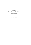
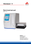
Remove the fill port adapter (see Fig. 1) by turning it downward.
Washer
Fig. 1: Fill port / fill port adapter
4. Decontaminate the washer of the fill port, the whole fill port and the top
surface of the sample inlet path, using a cotton swab saturated in
disinfectant.
5. Assemble the fill port and the sample drip tray.
6. Close bottle compartment cover.
7. Press the key "Interrupt" upon completion of this procedure.
The system performs a washing/drying procedure and will return to the
"Ready" screen.
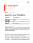
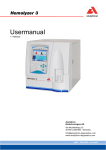
T&D disk
Fig. 2: Decontaminate T&D disk
1-8
Service Manual, AVL OMNI, Rev. 9.0, May 2000
1 Introduction
Decontaminate the individual T&D positions as follows:
Procedure
1. Activate the function program
"Options - Cleaning - Interrupt for Cleaning".
2. Open bottle compartment cover and analyzer cover.
3. Pull sample drip tray down and out.
Clean the sample drip tray under running water and decontaminate it.
4. Remove the fill port adapter (see Fig. 3) by turning it townward.
Washer
Fig. 3: Fill port adapter
5.
Decontaminate the washer of the fill port and the whole fill port using a
cotton swab saturated in disinfectant.
6. The fill port adapter can now be used as a tool. Insert the fill port adapter
into the slit of the holding disk and turn the holding disk a fourth of a turn
to the right or left. At the same time, hold the T&D disk firmly.
7. Remove, clean and decontaminate T&D disk.
8. Assemble T&D disk in reverse order.
9. Assemble sample drip tray.
10. Close bottle compartment cover and analyzer cover.
11. Press the key "Interrupt" upon completion of this maintenance procedure.
The system performs a washing/drying procedure and will return to the
"Ready" screen.
Touch screen
Procedure
1. Activate the function program
"Options - Cleaning - Clean display".
(The keys on the screen are deactivated for about 10 seconds!).
NOTE:
Decontaminate with damp cloth only using a disinfectant.
Do not use sprays!
After 10 seconds the screen will return into the active condition.
Surfaces
Decontaminate all outside surfaces including all covers (e.g. measuring
chamber covers, bottle compartment covers), as well as the outside surfaces of
the AutoQC module (if available), with the disinfectant according local
regulations.
Service Manual, AVL OMNI, Rev. 9.0, May 2000
1-9
1 Introduction
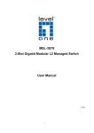
MSS tubes
Decontaminate the tubing paths of Solution 1, 3, 5, D and R3 2 with
AVL Deproteinizer.
Fig. 4: Remove bottles
1.
2.
3.
4.
5.
6.
Electrodes /
Measuring Chamber
Activate the function program
"Options - Cleaning - Cleaning of MSS-Tubes".
Open bottle compartment cover.
Remove and dispose the bottles 1, 3, 5, D and R.
Connect the shutdown tubing set to the corresponding suction tubes (see
chapter 3, section "Shutdown"). The tubes with the long rigid ends are
connected to Solutions 5, D and R.
Put the tubing harness in a container with AVL Deproteinizer.
Press the key "Continue" and follow the instructions on the screen.
Insert new bottles in the corresponding positions.
An internal cleaning with Solution 6 will be performed automatically during a
System Calibration after:
•
BG / ISE: 1000 sample measurements
•
tHb / COOX: 50 sample measurements
• MSS: 5000 sample measurements
An additional cleaning with AVL Deproteinizer should be performed only
when the measuring capillary is contaminated (protein residue) or if
components of the measuring path are being replaced.
NOTE:
2
1-10
The decontamination procedure is identical to the cleaning
procedure. If an electrode is exchanged, it has to be done before
the wetting process.
only, if MSS with Urea (BUN) is measured!
Service Manual, AVL OMNI, Rev. 9.0, May 2000
1 Introduction
BG measuring chamber
A cleaning of the BG measuring chamber is necessary only, when the
QC values of the BG electrode are outside the assay ranges.
An internal cleaning with Solution 6 will be performed automatically during a
System Calibration after 1000 sample measurements
Cleaning
Activate the function program
"Options - Cleaning - Module Cleaning".
set new limits
(number of samples)
with AVL Deproteinizer
actual sample counter
This button appears only if activated in the service area!
Fig. 5: Module Cleaning
Press "Start external cleaning".
The cleaning agent is introduced in the fill port like a sample (syringe or
capillary).
Press "Start internal cleaning".
If Solution 6 is available, an internal cleaning can also be activated!
Wetting
To wet the BG module after the cleaning process, several measurements (2-3)
with whole blood have to be performed.
If that is not possible or the decontamination / cleaning procedure tripped an
alarm for a complete module, activate:
"System - Util - Analyzer Actions - Fluid Actions - Wetting
Electrodes - Automatic / Manually".
NOTE:
Service Manual, AVL OMNI, Rev. 9.0, May 2000
Use the automatic wetting routine!
1-11
1 Introduction
Last for approx. 1 minute!
Press "BG-Electrode".
Attach a syringe or a capillary filled with wetting agent to the fill port area and
injects wetting agent until the glass tube is completely filled.
Follow the instructions on the screen.
CAUTION when handling blood! Biohazard!
ISE measuring chamber
It is expected that this cleaning procedure will depend on the typical sample
type of a laboratory (e.g.: physiological, pathological, fetal blood).
An internal cleaning with Solution 6 will be performed automatically after
every 1000 sample measurements.
Afterwards the measuring system must be conditioned with a wetting agent.
NOTE:
If the warning "Cl Electrode Dirty (Defect)!" appears,
cleaning of the Cl - -Electrode is recommended (see also
„Cleaning Instructions OMNI Cl - -Electrode“, AT0427 or
chapter 9, “Troubleshooting”).
Cleaning
Activate the function program "System - Util - Analyzer Actions - Fluid
Actions - Cleaning Routines".
Activate the ISE module and press "Start External Cleaning".
The cleaning agent is introduced in the fill port like a sample (syringe or
capillary).
Wetting
To wet the ISE module after the cleaning process, several measurements (2-3)
with whole blood have to be performed.
If that is not possible or the cleaning procedure tripped an alarm for a
complete module, activate "System - Util - Analyzer Actions - Fluid
Actions - Wetting Electrodes - ISE Electrodes - Automatic /
manually".
NOTE:
Use automatic mode exclusively!
Last for approx. 1 minute!
Press "ISE-Electrode".
Attach a syringe or a capillary filled with blood to the fill port area and inject
wetting agent until the glass tube is completely filled.
Follow the instructions on the screen.
CAUTION when handling blood! Biohazard!
1-12
Service Manual, AVL OMNI, Rev. 9.0, May 2000
1 Introduction
MSS measuring chamber
Since the MSS cassette should not come in contact with cleaning solution (will
cause damage of the sensor), use an MSS dummy cartridge for cleaning the
MSS measuring chamber.
After completion of the cleaning procedure make sure to moisten the new
MSS cassette with whole blood using the polarisation routine.
Do not use disinfectants containing alcohol for cleaning the inside of the
MSS measuring chamber cover. Use e.g. AVL Deproteinizer.
Use this cleaning procedure after each exchange MSS cassette but not often
than once a month.
Procedure
1. Remove the MSS cassette from the module.
2. Insert the MSS dummy cassette.
Activate the function program "Options - Cleaning - Module
Cleaning".
4. Select the MSS module.
3.
5. Press: "Start External Cleaning".
6. Introduce the external cleaning solution via the fill port in the same way a
sample is introduced (syringe or capillary).
7. An internal cleaning with Solution 6 will be performed automatically after
every 1000 sample measurements.
8. Insert a new MSS cassette.
Service Manual, AVL OMNI, Rev. 9.0, May 2000
1-13
1 Introduction
1-14
Service Manual, AVL OMNI, Rev. 9.0, May 2000
•
∆
•
SR ≥5.50
9.0, May 00/
•, ∆
•, ∆
•
2.0, Dec. 95/
SN 1146
•, ∆
•, ∆
•, ∆
3.0, March 96/
SN 1500
Modification (previous states of revision see chapter 10, "Previous revision levels")
New or addition !
Service Manual, AVL OMNI, Rev. 9.0, May 2000
•
∆
Electronic
Software
Service Manual
Manual revision/
applicable from serial number (SN) or
software revision number (SR)
Electronic
Software
Service Manual
Manual revision/
applicable from serial number (SN) or
software revision number (SR)
•
∆
•
SR ≥3.0
SR ≥2.0
•
•
•
5.0, Jan. 97/
4.0, July 96/
List of modifications, chapter 2 (Revisions)
•
∆
•
SR ≥4.0
6.0, Aug. 97/
•
∆
•
SR ≥4.5
7.0, May 98/
1
•
∆
•
8.0, Nov. 98/
SN 5000
SR ≥5.0
Service Manual, AVL OMNI, Rev. 9.0, May 2000
2
2 Revisions
2 REVISIONS
Electronic............................................................................................................................................ 2-1
Software .............................................................................................................................................. 2-3
Software version 1.xxx ...................................................................................................................... 2-3
Software version 2.xxx ...................................................................................................................... 2-4
Service Manual ................................................................................................................................... 2-6
Service Manual, AVL OMNI, Rev. 9.0, May 2000
2-I
2 Revisions
2 Revisions
Electronic
Id. no.
Revision
Assembly group
BA0866
Rev_6G
Mainboard
BB0520
Rev_8D
MC heat control
BB0532
Rev_11
MC ceramic heater
BB0533
Rev_44
Heat foil
BB0534
Rev_45
MC cover heat control
BB0539
Rev_58
Fluid level detector board
BB0548
Rev_5B
T&D control
BB0551
Rev_22
tHb board
BB0555
Rev_68
Motherboard
BB0582
Rev_45
SD heat control
BB0584
Rev_02
BFR board
BB0835
Rev_35
Hemolyzer board
I2:XP0263
BB0854
Rev_25
Aktor Control
I1:XP0223
BB0856
Rev_22
Aktor Board 6XQK
I1, 4, 6: XP0223
BB0857
Rev_33
Aktor Board 14XPC
I2, 4, 6, 9, 11, 13, 15: XP0223
BB0987
Rev_22
Aktor Board V23
I2: XP0223
BB0988
Rev_22
Aktor Board V24/V02
I2: XP0223
BB0986
Rev_22
Aktor Board V19
I2: XP0223
BB0984
Rev_22
Aktor Board V04/V03
I2: XP0223
BB0985
Rev_22
Aktor Board V13
I2: XP0223
BB0651
Rev_11
T&D sensor board
BB0657
Rev_02
Sensorprint-Waste
BB0663
Rev_13
PolyOx-KX-Control
I21 XP0139 CS: $CC93
I22 XZ0109 (3.04 ) CS: $73B6
BB0662
Rev_00
PolyOx-Digital
I5 XP0138 CS: $82B3 V3.04
BB0661
Rev_03
PolyOx-Analog
BB0725
Rev_00
PolyOx-Heat
EN0309
Rev_3.ß
A007 (B486SLC), AT96
SN > 1500
EN0329
Rev_7.5
AVLIFB (AT96)
SN > 2566
BB0722
Rev_22
Display IFR
SN > 1500
BB0808
Rev_00
IFR connector board
SN > 2800
EL0281
Rev_00
TFT LCD converter
SN > 2800
Service Manual, AVL OMNI, Rev. 9.0, May 2000
Drawing no.
SW Id. no.
I56: XP0080 CS: $D2E7
I95: XP0082 CS: $843A
I21/I77: XZ0109
CS: $73B6
I17: XP0079 CS: $EE78
2-1
2 Revisions
EN0292
Rev_02
Power supply unit
BB0739
Rev_22
SSE (MSS) Amp Glu/Lac
BB0741
Rev_47
SSE (MSS)-Mainboard
ZM0845
Rev_33
SSE (MSS) flexprint
ZM0804
Rev_33
SSE (MSS) connector board
BB0774
Rev_01
SSE (MSS) contact print
AutoQC (Option)
Id. no.
Revision
Assembly group
BB0760
Rev_13
AQC control board
BB0771
Rev_00
YZ-distributor board
BB0772
Rev_02
Z-distributor board
2-2
Drawing no.
SW Id. no.
I13: XP0177 CS: $2565
I23: XZ0145 CS: $65E0
Service Manual, AVL OMNI, Rev. 9.0, May 2000
2 Revisions
Software
Software version
1.xxx
AVL OMNI 1, 2, 4 and 5 (International)
Date of
release
05.09.1995
12.10.1995
19.12.1995
12.02.1996
Superior
version number
1.00
1.01
1.02
1.05
PCversion
1.600
1.800
1.900
1.902
HSversion
2.470
2.476
2.479
2.484
MMversion
2.450
2.455
2.457
2.460
COOXversion
-
HSversion
2.600
2.609
2.616
MMversion
2.500
2.501
2.501
COOXversion
1.900
1.904
1.907
HSversion
2.470
2.476
2.479
2.479
2.479
2.484
MMversion
2.450
2.455
2.457
2.457
2.458
2.460
COOXversion
-
HSversion
2.603
2.609
2.616
MMversion
2.500
2.501
2.501
COOXversion
1.903
1.904
3.001
Remark
First release
Deproteinizing
MC cartridge
SN
≥1000
≥1175
≈1150
≥1500
AVL OMNI 3 and 6 (International)
Date of
release
17.01.1996
20.02.1996
25.03.1996
Superior
version number
1.50
1.60
1.64
PCversion
1.930
1.937
1.942
Remark
First release
SN
≥1500
≥1512
≥1518
Remark
First release
SN
≥1000
≥1175
≈1150
≈1150
≈1150
≥1500
AVL OMNI 1, 2, 4 and 5 (USA)
Date of
release
05.09.1995
12.10.1995
19.12.1995
19.12.1995
25.12.1995
12.02.1996
Superior
version number
1.00
1.01
1.02
1.03
1.04
1.06
PCversion
1.600
1.800
1.900
1.901
1.901
1.903
USA version (Hct)
USA version (stddev x2)
Deproteinizing
MC cartridge
AVL OMNI 3 and 6 (USA)
Date of
release
29.01.1996
20.02.1996
25.03.1996
Superior
version number
1.51
1.61
1.65
PCversion
1.933
1.938
1.943
Service Manual, AVL OMNI, Rev. 9.0, May 2000
Remark
First release
SN
≥1500
≥1512
≥1518
2-3
2 Revisions
Software version
2.xxx
The software versions from AVL OMNI 1, 2, 4, 5 and 3, 6 and 9 have been
collected from version ≥ 2.0 on.
AVL OMNI 1 to 9
Date of
release
17.09.1996
30.09.1996
15.10.1996
Superior
version number
2.04
2.05
2.06
PCversion
2.099
2.099
2.099
HSversion
2.650
2.653
2.656
MMversion
2.566
2.566
2.566
COOXversion
1.938
1.938
1.938
27.01.1997
3.05
3.036
3.107
3.080
3.018
24.03.1997
3.10
3.504
3.112
3.080
3.018
12.05.1997
3.31
3.048
3.569
3.547
3.055
02.06.1997
3.32
3.048
3.569
3.548
3.055
18.08.1997
4.04
4.041
4.094
4.065
4.003
2-4
Remark
First release
Release for
AVL OMNI
7 to 9 only
SN
≈2155
≥2081
OMNI
OMNI
OMNI
OMNI
OMNI
OMNI
OMNI
OMNI
OMNI
OMNI
OMNI
OMNI
OMNI
OMNI
OMNI
OMNI
OMNI
OMNI
OMNI
OMNI
OMNI
OMNI
OMNI
OMNI
OMNI
OMNI
OMNI
OMNI
OMNI
OMNI
OMNI
OMNI
OMNI
1:
2:
3:
4:
5:
6:
1:
2:
3:
4:
5:
6:
1:
2:
3:
4:
5:
6:
1:
2:
3:
4:
5:
6:
1:
2:
3:
4:
5:
6:
7:
8:
9:
≥2117
≥2197
≥2084
≥2162
≥2125
≥2166
≥2370
≥2323
≥2415
≥2390
≥2434
≥2403
≥2411
≥2446
≥2455
≥2429
≥2471
≥2459
≥2408
≥2445
≥2462
≥2489
≥2527
≥2536
≥2411
≥2446
≥2455
≥2490
≥2532
≥2523
≥2651
≥2692
≥2682
Service Manual, AVL OMNI, Rev. 9.0, May 2000
2 Revisions
Date of
release
Superior
version number
PCversion
HSversion
MMversion
COOXversion
18.11.1997
4.12
4.110
4.117
4.084
4.003
20.04.1998
4.50
4.215
5.061
5.044
4.010
19.05.1998
4.51
4.218
5.061
5.044
4.010
18.11.1998
5.02
4.322
5.517
5.594
5.023
22.03.1999
5.10
4.330
5.531
5.602
5.024
Service Manual, AVL OMNI, Rev. 9.0, May 2000
Remark
SN
OMNI
OMNI
OMNI
OMNI
OMNI
OMNI
OMNI
OMNI
OMNI
OMNI
OMNI
OMNI
OMNI
OMNI
OMNI
OMNI
OMNI
OMNI
OMNI
OMNI
OMNI
OMNI
OMNI
OMNI
OMNI
OMNI
OMNI
OMNI
OMNI
OMNI
OMNI
OMNI
OMNI
OMNI
OMNI
OMNI
OMNI
OMNI
OMNI
OMNI
OMNI
OMNI
OMNI
OMNI
OMNI
1:
2:
3:
4:
5:
6:
7:
8:
9:
1:
2:
3:
4:
5:
6:
7:
8:
9:
1:
2:
3:
4:
5:
6:
7:
8:
9:
1:
2:
3:
4:
5:
6:
7:
8:
9:
1:
2:
3:
4:
5:
6:
7:
8:
9:
≥3069
≥2762
≥3035
≥3120
≥3015
≥3008
≥3111
≥3010
≥3063
≥3340
≥3209
≥3349
≥3340
≥3344
≥3352
≥3322
≥3324
≥3315
≥3403
≥3399
≥3377
≥3405
≥3401
≥3390
≥3321
≥3382
≥3388
≥5000
≥5000
≥5000
≥5000
≥5000
≥5000
≥5000
≥5000
≥5000
≥5270
≥5172
≥5256
≥5209
≥5259
≥5243
≥5232
≥5234
≥5239
2-5
2 Revisions
Date of
release
Superior
version number
PCversion
HSversion
MMversion
COOXversion
13.03.2000
5.50
5.520
5.541
5.610
5.025
Remark
SN
OMNI
OMNI
OMNI
OMNI
OMNI
OMNI
OMNI
OMNI
OMNI
1:
2:
3:
4:
5:
6:
7:
8:
9:
≥5960
≥5961
≥5977
≥5966
≥5936
≥5991
≥5922
≥5925
≥5969
Service Manual
Edition May 2000, Rev. 9.0
2-6
Service Manual, AVL OMNI, Rev. 9.0, May 2000
∆
∆
•
∆
∆
•
∆
∆
∆
•
∆
∆
•, ∆
∆
2.0, Dec. 95/
SN 1146
∆
•
•, ∆
∆
•
∆
•
•
3.0, March 96/
SN 1500
Modification (previous states of revision see chapter 10, "Previous revision levels")
New or addition !
Service Manual, AVL OMNI, Rev. 9.0, May 2000
•
∆
Application
Measurement parameters
Input values
Calculated parameters
Type of calibrations
Type of measurements
Sample dates
Sample volumes
Type of antikoagulants
Reagents
Measurement data
Environmental considerations - Instrument
Environmental considerations - Electrodes
Environmental considerations - Reagents
Electrical requirements
Data management
Classification
Dimension
Weight
Test certificates
Acoustic noise level
Manual revision/
applicable from serial number (SN) or
software revision number (SR)
•
∆
∆
SR ≥3.0
SR ≥2.0
∆
∆
∆
•, ∆
•
•
•, ∆
5.0, Jan. 97/
4.0, July 96/
∆
∆
•, ∆
•, ∆
•, ∆
∆
•
•
•, ∆
∆
∆
•, ∆
∆
SR ≥4.5
7.0, May 98/
∆
∆
•, ∆
∆
•, ∆
∆
•, ∆
∆
SR ≥4.0
6.0, Aug. 97/
List of modifications, chapter 3 (Description of functions / Specifications)
1
•
•
•
•
∆
•, ∆
∆
∆
∆
∆
•, ∆
∆
8.0, Nov. 98/
SN 5000
SR ≥5.0
∆
•
∆
•, ∆
•
SR ≥5.50
9.0, May 00/
Modification (previous states of revision see chapter 10, "Previous revision levels")
New or addition !
Service Manual, AVL OMNI, Rev. 9.0, May 2000
•
∆
Application
Measurement parameters
Input values
Calculated parameters
Type of calibrations
Type of measurements
Sample dates
Sample volumes
Type of antikoagulants
Reagents
Measurement data
Environmental considerations - Instrument
Environmental considerations - Electrodes
Environmental considerations - Reagents
Electrical requirements
Data management
Classification
Dimension
Weight
Test certificates
Acoustic noise level
Manual revision/
applicable from serial number (SN) or
software revision number (SR)
2
3 Description of Functions / Specifications
3 DESCRIPTION OF FUNCTIONS / SPECIFICATIONS
Application ......................................................................................................................................... 3-1
Main control with measurement modules ............................................................................................ 3-2
T&D module ..................................................................................................................................... 3-2
PC unit ............................................................................................................................................. 3-3
COOX module................................................................................................................................... 3-3
AutoQC module (option) ................................................................................................................... 3-3
The cooperation between single modules ............................................................................................ 3-3
AVL OMNI - Wiring and wiring without PC .................................................................................... 3-5
Measurement parameters .................................................................................................................... 3-7
Input values ........................................................................................................................................ 3-8
Calculated parameters ........................................................................................................................ 3-9
Type of calibrations .......................................................................................................................... 3-10
Type of measurements....................................................................................................................... 3-10
Sample dates / calibration times........................................................................................................ 3-11
Sample volumes ................................................................................................................................. 3-12
Type of anticoagulants ...................................................................................................................... 3-12
Reagents............................................................................................................................................ 3-13
Measurement data............................................................................................................................. 3-17
Environmental considerations – Instrument ..................................................................................... 3-17
Environmental considerations - Electrodes ....................................................................................... 3-18
Environmental considerations - Reagents ......................................................................................... 3-18
Electrical requirements ..................................................................................................................... 3-18
Data management.............................................................................................................................. 3-19
Classification .................................................................................................................................... 3-19
Dimensions ........................................................................................................................................ 3-19
Weight............................................................................................................................................... 3-19
Test certificates................................................................................................................................. 3-20
Acoustic noise level ........................................................................................................................... 3-20
Service Manual, AVL OMNI, Rev. 9.0, May 2000
3-I
3 Description of Functions / Specifications
3 Description of functions / Specifications
Application
The AVL OMNI is a modular, fully automatic, multi-processor controlled
"Critical Care Analyzer". It allows the measurement of blood gases, total
hemoglobin, electrolytes, hematocrit and metabolite in whole blood, serum,
plasma, dialysate and QC materials.
The analyzer allows a free selection of combinations of the offered parameters
(Random-Access-Combination-System), by the user.
The system is available in the following configurations:
AVL OMNI
Parameter
1
BG 1
2
BG and tHb (ctHb)
3
BG and COOX 2
4
BG, ISE 3 and Hct
5
BG, ISE, tHb and Hct
6
BG, ISE, COOX and Hct
7
BG, ISE, MSS 4 and Hct
8
BG, ISE, tHb, MSS and Hct
9
BG, ISE, COOX, MSS and Hct
A specific measurement module is necessary and responsible for each one or
for more of the parameter groups to be measured.
These modules and their parameters e.g. functions are:
• Main control with measurement control module
• T&D module
• PC unit
• COOX module
• AutoQC module (optional)
1
2
3
4
BG
COOX
ISE
MSS
Service Manual, AVL OMNI, Rev. 9.0, May 2000
=
=
=
=
(pH, PO 2 and PCO 2 )
(ctHb, O 2 Hb, HHb, COHb, MetHb, SulfHb)
(Na, K, Cl, iCa)
(Glucose, Lactate, Urea/BUN)
3-1
3 Description of Functions / Specifications
Main control with
measurement
modules
The main control steers and checks the actual calibration and measurement
functions of the AVL OMNI. A measurement control module is connected to
the main control which, depending upon the version of the analyzer, is
connected to the following measuring chambers over the Motherboard:
• BG measuring chamber:
Measurement of partial pressure PO 2 , partial pressure PCO 2 and pH value.
• ISE measuring chamber:
Measurement of ion concentrations of Na + , K + , Cl - , iCa ++ and Hct.
• MSS measuring chamber:
Measurement of glucose, lactate and urea
• tHb measuring chamber:
Measurement of total hemoglobin.
• COOX module:
Measurement of the hemoglobin derivatives O 2 Hb, HHb, COHb, MetHb,
SulfHb, ctHb and SO 2 .
The main control and measurement control module are located on a common
board, called Mainboard. The individual measurement chambers are connected
over the Motherboard. A detailed description of these modules can be found in
chapter 5 "Function Modules from A - Z".
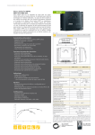
T&D module
80C196
Mainboard
Optobus
OPTORS 232
Main control
80C196
PC
Relayboard
COOX module
80C196
Measuring module
80C196
OptoBus
(AVL OMNI 3 and 6 only)
Motherboard
AutoQC module
80C196
(optional)
BG
ISE
tHb
MSS
Measuring chambers
pumps, valves, liquid sensors
switches, optical sensors
Power supply
Fig. 1: AVL OMNI - Block diagram
T&D module
3-2
This module is necessary for sample input and the control of calibration fluids.
A detailed description of this module can be found in Chapter 5 "Function
Modules from A - Z".
Service Manual, AVL OMNI, Rev. 9.0, May 2000
3 Description of Functions / Specifications
PC unit
An in the AVL OMNI integrated PC with a color touch screen and built-in
mass storage serves as a user interface. Further functions of this PC unit are
the storage of patient data and other specific data pertaining to the analyzer, as
well as the controlling of the built-in thermal printer and the use of interfaces.
A detailed description of this module can be found in Chapter 5 "Function
Modules from A - Z".
COOX module
Measurement of the hemoglobin derivatives O 2 Hb, HHb, COHb, MetHb,
SulfHb, ctHb and SO 2 .
A detailed description of this module can be found in chapter 5 "Function
Modules from A - Z".
AutoQC module
(option)
The cooperation
between single
modules
The AutoQC module is an unit which, together with the AVL OMNI,
automatically performs quality control measurements at times preprogrammed
by the user.
The main control is responsible for the functions of the analyzer and serves as
a superior position or "Master" for all other AVL OMNI modules. The user
functions or user surface, data storage and interface control are checked by the
PC. The main control and the PC communicate by means of a serial RS 232
interface, which is designed as an optical interface and is connected at the PC
with the COM1.
The communication from the main control to the specific modules is
established by a serial optical ringbus, the so-called Optobus. Only the part of
the ringbus from the main control to the measurement control module is an
electrical connection, since both modules are located on a printed circuit
board. Each module has an address and can be reached by the main control or
by another module. The main control can give the transmitting rights to the
specific, single modules. The main control and the measurement control
module to a certain extent, steers and checks the pumps and valves, as well as
the optical sensors for the aspiration process and controls the fill levels in the
reagent bottles. The measurement module is responsible for recording data
resulting from sensor signals from the specific measuring chambers, as well as
for temperature control.
The following brief examples describe the distribution of functions and the
respective communication of each module or PC:
• User inserts capillary for measurement: The T&D module recognizes the
inserted capillary and sends the corresponding information to the main
control on the Optobus. The main control transmits this to the PC by means
of the optical serial interface, causing a change of display The PC initiates
the further functions at the main control which are necessary for
measurement.
• A user would like to perform a T&D test and calls up this function on the
display: The PC sends the appropriate message to the main control, which
identifies it as a so-called macro command which is intended for the T&D
module, and sends the information further to the Optobus. In this case, the
T&D module performs the test and transmits the o.k. or the error report in
the same manner.
Service Manual, AVL OMNI, Rev. 9.0, May 2000
3-3
3 Description of Functions / Specifications
One exception pertaining to the flow of communication exists at the main
control and measurement control module concerning the valve gear. Both
controls have their own control circuit for the valves and a so-called "wired or
circuit" which allows the turning on with both controls when necessary for
reasons of speed. It is to be noted, that the valve gear for the valve test is only
performed by the main control.
The communication on the optical ringbus (Optobus) allows an automatic
hardware echo, which means that the transmitted information will be received,
after running through the loop, where it is checked for correctness. At the same
time, an interruption will be recognized immediately.
With the help of the software-handshake and checksum, the communication
between the PC and the main control is checked for correctness during
transmission. In addition, the connection is continuously controlled.
The PC gives the superior functions and the main control the specific
commands, in accordance to the work cycles, further to the modules.
Therefore, the measurement module for example, gives pre-calculated voltage
values during measurement, the PC calculates the respective measurement
values based on the previously determined calibration values and existing
correction values.
3-4
Service Manual, AVL OMNI, Rev. 9.0, May 2000
3 Description of Functions / Specifications
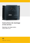
AVL OMNI - Wiring
and wiring without
PC
Aktor Board
V23
BB0987
Aktor Board
V24/V02
BB0988
Aktor Board
V19
BB0986
Aktor Board
6XQK
BB0856
Aktor Board
V14XPC
BB0857
Valve bus
Aktor Board
V04/V03
BB0984
Aktor Board
V13
BB0985
Valve bus
J3
Aktor
Control Board
Optobus
OptoRS 232
to PC (COM1)
BB0854
SS4
T&D module
SS6
BP1621
(AVL OMNI 7-9)
AVL OMNI 1-6
AVL OMNI 7-9
Fan
SS4
Mainboard
SS2
J1
rear panel
BV1798
SS1
2x1
J4, J7, J6 for internal use only
BA0866
Vacuum
sensor
SS3
Power supply
J1
+5V, +/-12V, +24V
EN0292
J2
96
3
9
Sample
distributor
14
4
OMNI 1-3: BP1945
OMNI 4-6: BP1677
OMNI 7-9: BP2290
96
J1
J16
J3
BC0233
96
J2
V24 P
GNDP1
J3
Motherboard
J5
J15
J14
J12
J17
J13
J6, J7, J21, J22, J23, J25 not used
BB0555
J11
J18
J19
J20
J9
J10
J8
J4/3
2
Vac. pump
BFR board
5
BB0584
2
Fluid level
det. board
14
2
BB0539
2
2
4
40
40
40
20
Mix
valve
10
Bottle comp. contact
BP1644
white marking
opto transmitter
MC...measuring chamber
all available
measuring modules
indicated
PP
BGMC
ISEMC
MSSMC
tHbMC
Hemolyzer
BP1846
BP1755
BP1634
BP2046
BP1626
BP2434
Fig. 2: AVL OMNI - Internal wiring
The wiring of the PC tower with the power supply unit is shown on a separate
circuit diagram. These circuit diagrams and more detailed information about
the modules can be found in chapter 5, "Function Modules from A - Z".
The central wiring element of the analyzer is the Motherboard.
The Mainboard, with both of the functional units main control with
measurement modules is directly connected to the Motherboard with the
connector (J1, J2, J3). Only the photoconductor connection for the Optobus
and to the optical RS 232 interface of the PC, and photoconductor connection
to the optical sensors SS1 to SS4 (SS6 at AVL OMNI 7, 8 and 9) are directly
connected to the Mainboard. The transmitter plugs are either white or marked
with white at the optical data connections.
Peristaltic pump (PP): The stepper motor of the pump is directly connected to
the Motherboard at J11. The control for the stepper motor is located on the
Mainboard.
Service Manual, AVL OMNI, Rev. 9.0, May 2000
3-5
3 Description of Functions / Specifications
The vacuum pump is connected at J13. The pre-switched BFR board
suppresses disturbances, which can be caused by the vacuum pump directcurrent motor.
The fan is located on the rear of the analyzer and the corresponding plug on
the Motherboard is J15. A further fan is located in the PC tower.
The vacuum sensor for the under pressure control of the wash cycles is
connected at J14 on the Motherboard.
The control switch for the cover of the bottle compartment is connected at J17
of the Motherboard with a small laced wiring harness also leading to the
contact of the sample distributor.
Detailed information pertaining to the components mentioned above, can be
found in chapter 5, "Function Modules from A - Z".
3-6
Service Manual, AVL OMNI, Rev. 9.0, May 2000
3 Description of Functions / Specifications
Measurement parameters 5
Parameter
Unit
Displayed
range
Resolution
Specified
range
Used sample
type
Precision * )
Blood gas module
PO 2
PCO 2
pH
mmHg
mmHg
0 to 800
4 to 200
6.0 to 8.0
0.1
0.1
0.001
60 to 140
15 to 70
6.8 to 7.6
Baro
mmHg
300 to 800
0.1
20 to 250
0.2 to 20
20 to 250
0.1 to 6.0
10 to 80
550 to 800
T
T
T, Q
S
air pressure
SD < 1.2
SD < 1.0
SD < 0.005
SD < 0.012
typ. ± 2
0.1
0.01
0.1
0.001
0.1
120 to 170
3.0 to 6.0
70 to 130
0.6 to 1.5
20 to 60
T,
T,
T,
T,
T
SD
SD
SD
SD
not
3 to 24
0.1
3 to 24
T
SD < 0.2
0.0
0.0
0.0
0.0
0.0
0.1
0.1
0.1
0.1
0.1
0.0
0.0
0.0
0.0
not
T
T
T
T
T
SD
SD
SD
SD
not
SD < 0.1 or
CV < 3%
SD < 0.1 or
CV < 3%
SD < 0.1 or
CV < 3%
SD < 0.3 or
CV < 3 %
Electrolyte module
Na
K
Cl
Ca
Hct
mmol/L
mmol/L
mmol/L
mmol/L
%
S,
S,
S,
S,
A,
A,
A,
A,
Q
Q
Q
Q
< 1.5
< 0.05
< 1.0
< 0.03
specif.
Haemoglobin module
ctHb
g/dL
CO-oximetry module
O 2 Hb
HHb
COHb
MetHb
SulfHb
%
%
%
%
%
to
to
to
to
to
100.0
100.0
100.0
100.0
100.0
to 100.0
to 100.0
to 100.0
to 20.0
specif.
< 1.2
< 1.2
< 0.3
< 0.2
specif.
Metabolite module
Glu
mmol/L
0.5 to 40
0.1
1 to 10
T, S, Q
Lac
mmol/L
0.2 to 20
0.1
0.5 to 5
T, S, Q
Urea
mmol/L
0.5 to 40
0.1
2 to 10
T, S, Q
BUN
mg/dL
1.4 to 112
0.1
5.6 to 28.0
T, S, Q
* ) 20 days" within run precision" after NCCLS
Specified for:
T ...... tonometered blood
Q.....aqueous QC material
A ..... Acetate
S ......Serum or Plasma
5
The instrument is designed for the measurement of parameters in whole blood
and serum and the accuracy of these measurement values is tested.
The accuracy of measurement values in aqueous AVL Control is ensured
through appropriate composition of the solutions as well as appropriate
corrective measures in the QC program (if needed) regarding the differences
between these controls and biological sample material.
The accuracy of measurement values in other aqueous solutions cannot be
ensured (e.g. due to unknown interference’s, and/or missing or insufficient
buffer systems, and/or differences in ionic strength and diffusion potential
compared to biological sample material).
Service Manual, AVL OMNI, Rev. 9.0, May 2000
3-7
3 Description of Functions / Specifications
Input values
•
•
•
•
•
•
•
•
•
•
•
•
•
•
•
•
•
•
•
•
•
•
•
•
•
•
•
•
•
•
•
•
•
•
•
•
•
•
•
•
•
•
•
Patient code
Last name
First name
Middle initial
Insurance Number
Sample type
Sex
Date of birth
Blood type
Puncture site
User
Technician
Physician
Accepted
ALLEN test
Time of collection
Date of collection
Transfer time:
Transfer date:
Comments
Accession Code
Department
*)
** )
*** )
**** )
Location
TVOL *)
MVOL *)
Vent. Modus *)
PIP *)
LPM *)
ITIME *)
ETIME *)
SRATE *)
ARATE *)
PEEP *)
Glu
Lac
BUN
Temp
a/f
R
FIO 2
P 50 **)
ctHb (E) ***)
+ 2 free definable customer lines
so called "respiration dates", only used when the patient is connected
to a respirator.
Only at AVL OMNI 3, 6 and 9 a calculated parameter!
tHb replacement value, if tHb could not be measured!
Only at AVL OMNI 1 to 6 an input value!
All suitable input parameters (e.g.: patient ID, operator ID) can also be entered
with the aid of the barcode scanner.
3-8
Service Manual, AVL OMNI, Rev. 9.0, May 2000
3 Description of Functions / Specifications
Calculated parameters6
Range
pH at patient temperature ...............................................................
Standard pH value ..........................................................................
PCO 2 at patient temperature ...........................................................
PO 2 at patient temperature..............................................................
Hydrogen ion concentration ............................................................
Hydrogen ion concentration at patient temperature ..........................
Bicarbonate concentration ..............................................................
Standard bicarbonate ......................................................................
Total CO 2 concentration in plasma ..................................................
Total CO 2 concentration in blood ....................................................
Functional (available) oxygen saturation .........................................
Functional oxygen saturation (uses blood gas values).......................
Fractional oxygen saturation ..........................................................
Base excess in blood ......................................................................
Base excess in vivo ........................................................................
Buffer bases...................................................................................
Oxygen concentration (arterial) (PO 2 , SO 2 , COHb, MetHb, ctHb)....
Half Saturation Tension of Oxygen in Partial Pressure of Oxygen ....
Alveolar arterial oxygen partial pressure .........................................
Alveolar arterial oxygen partial pressure at patient temperature .......
Alveolar arterial oxygen partial pressure difference .........................
Alveolar arterial oxygen partial pressure difference
at patient temperature .....................................................................
Arterial-venous oxygen content difference ......................................
Alveolar arterial oxygen partial pressure ratio .................................
Alveolar arterial oxygen partial pressure at patient temperature .......
Respiratory index ...........................................................................
Respiratory index at patient temperature .........................................
Shunt .............................................................................................
Standardized ionized calcium .........................................................
Anion gap ......................................................................................
Mean corpuscular hemoglobin concentration ...................................
Hct as a function of tHb .................................................................
Oxygen capacity (only COOX) .......................................................
BE at actual oxygen saturation........................................................
Hb-Indicator ..................................................................................
Osmolality .....................................................................................
Oxygen Extraction Ratio ................................................................
Blood Urea Nitrogen
*)
** )
*** )
**** )
6
Only
Only
Only
Only
t
pH
pH st
PCO 2 t
PO 2 t
cH +
cH t
cHCO 3 cHCO 3 - st
cWCO 2 (P)
cWCO 2 (B)
SO 2
SO 2 (c)
FO 2 Hb
BE
BE ecf
BB
ctO 2
3 50 * )
PAO 2
PAO 2 t
AaDO 2
AaDO 2 t
avDO 2
a/AO 2
a/AO 2 t
RI
RI t
Os/Ot
niCa ++
(pH=7.4)
AG
MCHC
Hct(c)
BO 2
BE (act)
HbI ** )
Osm *** )
OER
BUN
6 ........... 8
6.5 ........ 8.5
0 ........... 200 mmHg
0 ........... 742 mmHg
10 ......... 1000 nmol/l
10 ......... 1000 nmol/l
1 ........... 100 mmol/l
1 ........... 100 mmol/l
1 ........... 100 mmol/l
1 ........... 100 mmol/l
0 ........... 100 %
0 ........... 100 %
0 ........... 100 %
-40 ........ +40 mmol/l
-40 ........ +40 mmol/l
0 ........... 100 mmol/l
0 ........... 56 vol%
0 ........... 100 mmHg
40 ......... 730 mmHg
40 ......... 730 mmHg
0 ........... 742
0.7 ........ 0.9
0.7 ........ 0.9
0.1 ........ 6.0 mmol/l
3 ........... 30 mmol/l
at AVL OMNI 3, 6 and 9 a calculated parameter!
displayed, if tHb is not measured
in the versions of AVL OMNI™ 7 – 9
in the versions of AVL OMNI™ 7 – 9 with Urea
Displayed calculated values are not limited!
Service Manual, AVL OMNI, Rev. 9.0, May 2000
3-9
3 Description of Functions / Specifications
Type of
calibrations
Frequency
System calibration .............. every 24 hours
(setup 12 or 24 hours)
2P calibration ..................... every 12 hours
(setup 4, 6, 8, 10, 12 hours)
1P calibration ..................... every 0.5 hours or every hour
1P calibration
after every sample............... in measurement included
tHb calibration ................... every 100 days, (manual)
Warm-up ............................ on demand
Electrode change ................ on demand
MSS cassette change ........... on demand
COOX cal........................... during system calibration
1P MSS calibration ............. Every 15 minutes within the first 4
hours after an MSS polarization.
2P MSS calibration ............. Every 2 hours within the first 5
hours after an MSS polarization,
thereafter at selected intervals.
For urea: every 4 hours between 5
and 24 hours, thereafter at default
intervals.
Duration [min]
AVL OMNI
1-5/6
7-8/9
7-8/9 7
11/12.5
16.6/18.4
18.4/19.9
7
1.5
12.6
3.3
14.4
4.3
3
10
19
60
1.5
3
10
19
60
1.5
3
10
19
60
1.5
-
1.8
2.8
-
5.6
7.4
Type of measurements
pH, PCO 2 , Urea .............................
PO 2 ...............................................
Na, K, Cl, Ca .................................
tHb ...............................................
Hct................................................
COOX ...........................................
Glu, Lac ........................................
7
3-10
potentiometric
amperometric
direct potentiometric
photometric
conductance
photometric
amperometric
Valid with MSS with Urea (BUN) only!
Service Manual, AVL OMNI, Rev. 9.0, May 2000
3 Description of Functions / Specifications
Sample dates / calibration times
Activated /
Installed modules
Optimal sample rate
[sample/hours]
Syringe Capillary
Typical calibration times
[min]
Sys. cal
2P cal.
1P cal.
BG
40
36
11
7
1.5 8
BG-tHb
36
32
11
7
1.5 6
BG-COOX
36
32
12.5
7
1.5 6
BG-ISE
40
36
11
7
1.5 6
BG-ISE-tHb
35
32
11
7
1.5 6
BG-ISE-COOX
35
32
12.5
7
1.5 6
ISE-tHb
39
34
11
7
1.5 6
ISE-COOX
39
34
12.5
7
1.5 6
tHb
40
35
COOX
40
35
ISE
42
38
11
7
1,5 6
MSS-(Urea)
32 (30)
28 (26)
5.6 (7.4)
5.6 (7.4)
1.8 (2.8)9
BG-MSS-(Urea)
30 (29)
27 (26)
16.6 (18.4)
12.6 (14.9)
3.3 (4.3)10
BG-ISE-MSS-(Urea)
30 (29)
26 (26)
16.6 (18.4)
12.6 (14.9)
3.3 (4.3) 8
ISE-MSS-(Urea)
32 (30)
28 (26)
16.6 (18.4)
12.6 (14.9)
3.3 (4.3) 8
tHb-MSS-(Urea)
31 (31)
27 (27)
5.6 (7.4)
5.6 (7.4)
1.8 (2.8) 7
BG-ISE-MSS-(Urea)-tHb
29 (28)
25 (24)
16.6 (18.4)
12.6 (14.4)
3.3 (4.3) 8
BG-ISE-MSS-(Urea)-COOX
28 (27)
25 (23)
18.1 (19.9)
12.6 (14.4)
3.3 (4.3) 8
8
if calibration interval is one hour, typ. calibration time: +0.5 min
9 if calibration interval is one hour, typ. calibration time: +0.9 min
10 if calibration interval is one hour, typ. calibration time: +1.4 min
Service Manual, AVL OMNI, Rev. 9.0, May 2000
3-11
3 Description of Functions / Specifications
Sample volumes
Typical sample
volumes* ) [µl]
Typical sample
volumes** ) [µl]
Volume limitation by
sample sensor [µl]
BG
40
46
65
BG-tHb
80
84
100
BG-COOX
80
84
100
BG-ISE
70
76
86
BG-ISE-tHb
110
115
140
BG-ISE-COOX
110
115
140
BG-ISE-MSS
121
129
200
BG-ISE-MSS-tHb
161
169
200
161
BG-ISE-MSS-COOX
*)
typical for Hct < 40%
** )
typical for 40% < Hct < 75%
169
200
Activated /
installed modules
Type of
anticoagulants
Lithium heparin or balanced heparin mixtures (as often used for samples taken also for electrolyte analysis)
are the only acceptable anticoagulants for blood gas, ISE and MSS analysis. Other anticoagulants such as
EDTA, citrate, oxalate, fluoride and ammonium containing anticoagulants have a significant effect on blood
pH and should not be used.
3-12
Service Manual, AVL OMNI, Rev. 9.0, May 2000
3 Description of Functions / Specifications
Reagents
Solution A
Order number:
Use:
Contents:
Solvent:
Active ingredients:
Storage temp.:
Stability:
Solution B
Order number:
Use:
Contents:
Solvent:
Active ingredients:
Storage temp.:
Stability:
Solution C
Order number:
Use:
Contents:
Solvent:
Active ingredients:
Storage temp.:
Stability:
Solution D (GLU/LAC)
Order number:
Use:
Contents:
Solvent:
Active ingredients:
Storage temp.:
Stability:
Service Manual, AVL OMNI, Rev. 9.0, May 2000
BP 1893
Rinse solution for sample path.
1 package contains 6 ready to use containers
with 820 ml each.
Water
aqueous solution, Tensides
15 - 30 °C
Expiration date & lot number are printed on
each container label.
BP 1892
Solution for calibration of Na + , K + , iCa ++ ,
Cl - , pH and PCO 2 after controlled mixing with
Solution B and C.
1 package contains 6 ready to use containers
with 820 ml each.
Water
Electrolytes, carbonate, bicarbonate
15 - 30 °C
Expiration date & lot number are printed on
each container label.
BP 1891
Solution for calibration of Na + , K + , iCa ++ ,
Cl - , pH and PCO 2 after controlled mixing with
Solution B and C.
1 package contains 6 ready to use containers
with 480 ml each.
Water
Electrolyte and basic buffer components
15 - 30 °C
Expiration date & lot number are printed on
each container label.
BP 2279
Standby- and rinse solution for metabolite
sensors (glucose and lactate only)
1 package contains 6 ready to use containers
with 480 ml each.
Water
Electrolyte and buffer components
2 - 25 °C
Expiration date & lot number are printed on
each container label.
3-13
3 Description of Functions / Specifications
Solution D (GLU/LAC/UREA)
Order number:
Use:
Contents:
Solvent:
Active ingredients:
Storage temp.:
Stability:
Solution R
Order number:
Use:
Contents:
Solvent:
Active ingredients:
Storage temp.:
Stability:
Solution 1 (GLU/LAC)
Order number:
Use:
Contents:
Solvent:
Active ingredients:
Storage temp.:
Stability:
Solution 1 (GLU/LAC/UREA)
Order number:
Use:
Contents:
Solvent:
Active ingredients:
Storage temp.:
Stability:
3-14
BP 2191
Standby- and rinse solution for metabolite
sensors (glucose, lactate and urea)
1 package contains 6 ready to use containers
with 480 ml each.
Water
Electrolyte and buffer components, urea,
ammonium
2 - 25 °C
Expiration date & lot number are printed on
each container label.
BP 1894
Reference electrolyte solution for calibration
pH-, ISE- and urea- electrodes.
1 package contains 12 ready to use containers
with 100 ml each.
Water
Potassium Chloride, 1.2 mol /l
15 - 30 °C
Expiration date & lot number are printed on
each container label.
BP 2248
Solution for calibration of glucose and lactate.
1 package contains 4 ready to use containers
with 40 ml each.
Water
Electrolyte, buffer components
4-Acetamidophenol
2 - 25 °C
Expiration date & lot number are printed on
each container label.
BP 2292
Solution for calibration of glucose, lactate and
urea.
1 package contains 4 ready to use containers
with 38 ml each.
Water
Electrolyte, buffer components
4-Acetamidophenol, urea, ammonium
2 - 8 °C
Expiration date & lot number are printed on
each container label.
Service Manual, AVL OMNI, Rev. 9.0, May 2000
3 Description of Functions / Specifications
Solution 2
Order number:
Use:
Contents:
Solvent:
Active ingredients:
Storage temp.:
Stability:
Solution 3 (GLU/LAC)
Order number:
Use:
Contents:
Solvent:
Active ingredients:
Storage temp.:
Stability:
Solution 3 (GLU/LAC/UREA)
Order number:
Use:
Contents:
Solvent:
Active ingredients:
Storage temp.:
Stability:
Solution 4
Order number:
Use:
Contents:
Solvent:
Active ingredients:
Storage temp.:
Stability:
Service Manual, AVL OMNI, Rev. 9.0, May 2000
BP 1898
Solution for conditioning the Na + -Electrode.
1 package contains 4 ready to use containers
with 40 ml each.
Water
Ammonium hydrogen difluorid, 100 mmol/l
15 - 30 °C
Expiration date & lot number are printed on
each container label.
BP 2249
Solution for calibration of glucose and lactate.
1 package contains 4 ready to use containers
with 40 ml each.
Water
Electrolyte, buffer components,
glucose, lactate
2 - 25 °C
Expiration date & lot number are printed on
each container label.
BP 2193
Solution for calibration of glucose, lactate and
urea.
1 package contains 4 ready to use containers
with 38 ml each.
Water
Electrolyte, buffer components,
glucose, lactate, urea, ammonium
2 - 8 °C
Expiration date & lot number are printed on
each container label.
BP 2068
Solution for calibration of PO 2 -zero point.
1 package contains 4 ready to use containers
with 40 ml each.
Water
Sodium sulfite and sodium hydrogen sulfite,
total 600 mmol/l
15 - 30 °C
Expiration date & lot number are printed on
each container label.
3-15
3 Description of Functions / Specifications
Solution 5 (GLU/LAC)
Order number:
Use:
Contents:
Solvent:
Active ingredients:
Storage temp.:
Stability:
Solution 5 (GLU/LAC/UREA)
Order number:
Use:
Contents:
Solvent:
Active ingredients:
Storage temp.:
Stability:
Solution 6
Order number:
Use:
Contents:
Solvent:
Active ingredients:
Storage temp.:
Stability:
AVL Deproteinizer
Order number:
Use:
Contents:
Solvent:
Active ingredients:
Storage temp.:
Stability:
3-16
BP 2278
Solution for calibration of glucose and lactate.
1 package contains 6 ready to use container
with 100 ml each
Water
Electrolyte, buffer components,
glucose, lactate
2 - 25 °C
Expiration date & lot number are printed on
each container label.
BP 2194
Solution for calibration of glucose, lactate and
urea.
1 package contains 6 ready to use container
with 98 ml each
Water
Electrolyte, buffer components,
glucose, lactate, urea, ammonium
2 - 25 °C
Expiration date & lot number are printed on
each container label.
BP 2562
Cleaning solution for BG/ISE electrodes and
COOX/MSS module (not for MSS cassettes).
1 package contains 2 ready to use container
with 23 ml each
Water
Sodiumhypochlorite: < 1% active chlorine,
Neodisher MA: 0.35%
2 - 30 °C
Expiration date & lot number are printed on
each container label.
BP 0521
Cleaning solution for sample path
1 package contains 1 ready to use container
with 125 ml
Water
Sodiumhypochlorite, < 2% active chlorine
15 - 30 °C
Expiration date & lot number are printed on
each container label.
Service Manual, AVL OMNI, Rev. 9.0, May 2000
3 Description of Functions / Specifications
Hb Calibrator
Order Number:
Use:
Contents:
Solvent:
Active Ingredients:
Storage Temp.:
Stability:
NOTE:
BP 1360
Solution for calibration of tHb
1 package contains 5 ampoules with 2 ml each.
Water
Potassiumdihydrogenphosphate, Disodiumhydrogenphosphate, Amaranth, Tensides
15 - 30 °C
Expiration date & lot number are printed on
each ampoule label
Use of calibration solutions or electrodes not manufactured for
AVL could void the warranty.
A Waste container is provided, once used, the Waste container
holds biological fluids which may be potentially infectious;
handle with appropriate care to avoid skin contact or ingestion.
FOR IN-VITRO DIAGNOSTIC USE.
Measurement data
Units ............................. SI, conv.
Environmental considerations – Instrument
Operating conditions:
Temperature .................. +15 °C to +31 °C(59 °F to 87,8 °F)
Humidity ....................... AVL OMNI 1 - 6, 20 to 95 %
AVL
up to
up to
up to
up to
OMNI 7, 8, 9 (measuring chamber temperature adjustable):
70 %, if temp. < 31 °C, (MC Temp. 25 °C)
83 %, if temp. < 28 °C, (MC Temp. 25 °C)
90 %, if temp. < 27 °C, (MC Temp. 25 °C)
95 %, if temp. < 31 °C, (MC Temp. 30 °C)
Measuring chamber
temperature:
BG & ISE ...................... 37 °C ± 0.2 °C (98.6 °F ± 32.36 °F)
MSS .............................. 25 °C ± 0.2 °C (77.0 °F ± 32.36 °F) or
30 °C ± 0.2 °C (86.0 °F ± 32.36 °F) adjustable
COOX ........................... 37 °C ± 0.2 °C (98.6 °F ± 32.36 °F)
tHb ................................ 37 °C ± 0.5 °C (98.6 °F ± 32.9 °F)
Storage and
transport conditions:
Temperature .................. - 20 °C to + 60 °C (-4 °F to + 140 °F)
Humidity ....................... 0 - 95 % (non-condensing)
Shock resistance ............ < 50 g
Service Manual, AVL OMNI, Rev. 9.0, May 2000
3-17
3 Description of Functions / Specifications
Environmental considerations - Electrodes
Operating conditions:
Temperature ..................................
Humidity .......................................
Storage conditions in
original packages:
Temperature ..................................
Humidity .......................................
Transport condition in
original packages:
Temperature ..................................
Humidity .......................................
Shock ............................................
+37 °C (98.6 °F) for BG and ISE
+25 °C (77.0 °F) or +30 °C (86.0 °F) for MSS
20 to 85 %
+15 °C to +30 °C (59.0 °F to 86.0 °F) for BG and ISE
+2 °C to +8 °C (35.6 °F to 46.4 °F) for MSS
20 to 80 %
-5 °C to +40 °C (23.0 °F to 104.0 °F), over a 3-day period
-20 °C to +50 °C (-4.0 °F to 122.0 °F) for MSS, over a 3-day period
0 - 80 %
< 50 g
Environmental considerations - Reagents
Operating conditions:
Temperature ..................................
Humidity .......................................
+15 °C to +35 °C (59.0 °F to 95.0 °F)
20 to 95 %
Storage conditions in
original packages:
Temperature ..................................
Humidity .......................................
see page 3-13
20 to 95 %
Transport condition in
original packages:
Temperature ..................................
Air pressure...................................
Shock ............................................
Solution A, B, C, R, 2, 4, 6: -20 °C to +50 °C
(-4.0 °F to 122.0 °F); max. 2 weeks
Solution 1, 3, 5 and 5: -20 °C to +35 °C (-4.0 °F to 95.0 °F);
max. 2 weeks
850 - 1050 mbar abs. (air cargo)
< 30 g
Electrical requirements
Voltage range ................................
Frequency......................................
Power consumption (max.) .............
Fuse at device................................
3-18
100 - 240 V AC (+6%/-10% permissible tolerance)
50 - 60 Hz
250 VA (according to IEC 1010-1 (EN61010-1), the measured value is
allowed to exceed 10% with consideration of all optional AVL
accessory devices)
2 x 2.5 AT
Service Manual, AVL OMNI, Rev. 9.0, May 2000
3 Description of Functions / Specifications
Data management
Integrated PC (5x86) with ≥ 500 MB hard disk (2.5“ or 3.5", floppy drive 3.5")
Screen
color LCD (10") with touch screen handling
Thermal printer .............................. capable for graphics, width of paper approx. 120 mm,
paper length appr. 50 m / roll
Barcode scanner
standard
External keyboard
option
Interfaces....................................... 4 x RS 232, 1 x parallel, AUI Ethernet network
Classification
Safety category ..............................
Instrument type ..............................
Operation type ...............................
Protective system ...........................
Ex-protection .................................
I
B (ÖVE - MG/EN 60 601-1, IEC 601-1)
For continuous operation
IP20
The device is not specified for operation inside explosion hazardous
areas.
Dimensions
Width ............................................
Depth ............................................
Height ...........................................
55 cm
47 cm
60 cm
(21.67 Inch)
(18.52 Inch)
(23.64 Inch), with touch screen open
AutoQC module (option):
Width ............................................
Depth ............................................
Height ...........................................
21 cm
(8.27 Inch)
38 cm
(14.00 Inch)
15.6 cm (6.15 Inch)
Weight
AVL OMNI 1 to 9 .......................
AVL OMNI 1 to 9
ready for delivery...........................
app. 33 kg
app. 44 kg
AutoQC module (option):
app. 4.5 kg
Service Manual, AVL OMNI, Rev. 9.0, May 2000
in carton, incl. Operator's Manual, accessories and
cables
3-19
3 Description of Functions / Specifications
Test certificates
ÖVE ...........................................
CSA ...........................................
CE-conformity...............................
tested according to the standard EN61010-1, as well as EN60601-1
tested according to the standard C22.2 No. 1010.1-92
The analyzer corresponds to the directives 89/336/EEC (EMCdirectives), tested according to the generic standard EN50081-1 and
EN00081-2, as well as 73/23/EEC (Low Voltage Directive with
addition 93/68/EWG), tested according to EN61010-1, and is allowed
to be labeled with the CE-marking.
Acoustic noise level
in all modes .................. max. 55 dB
3-20
Service Manual, AVL OMNI, Rev. 9.0, May 2000
∆
∆
∆
∆
SR ≥5.50
9.0, May 00/
•, ∆
•, ∆
2.0, Dec. 95/
SN 1146
•, ∆
3.0, March 96/
SN 1500
Modification (previous states of revision see chapter 10, "Previous revision levels")
New or addition !
Service Manual, AVL OMNI, Rev. 9.0, May 2000
•
∆
Installation
Shutdown procedure
Installation of the AutoQC module (option)
Options
Manual revision/
applicable from serial number (SN) or
software revision number (SR)
Installation
Shutdown procedure
Installation of the AutoQC module (option)
Options
Manual revision/
applicable from serial number (SN) or
software revision number (SR)
∆
∆
∆
SR ≥3.0
SR ≥2.0
•, ∆
•
5.0, Jan. 97/
4.0, July 96/
•, ∆
•
•, ∆
SR ≥4.0
6.0, Aug.. 97/
List of modifications, chapter 4 (Installation / Shutdown)
∆
∆
•, ∆
SR ≥4.5
7.0, May 98/
1
•, ∆
•, ∆
•, ∆
∆
8.0, Nov. 98/
SN 5000
SR ≥5.0
Service Manual, AVL OMNI, Rev. 9.0, May 2000
2
4 Installation / Shutdown
4 INSTALLATION / SHUTDOWN
Installation.......................................................................................................................................... 4-1
Shutdown procedure ......................................................................................................................... 4-11
Less than 24 hours........................................................................................................................... 4-11
More than 24 hours ......................................................................................................................... 4-11
Installation of the AutoQC module (option) ...................................................................................... 4-14
Options .............................................................................................................................................
Reusable Waste container ................................................................................................................
External Waste container .................................................................................................................
Barcode scanner ..............................................................................................................................
Keyboard ........................................................................................................................................
Paper take-up unit ...........................................................................................................................
MSS Conditioning System ...............................................................................................................
AVL OMNILink™ ..........................................................................................................................
Service Manual, AVL OMNI, Rev. 9.0, May 2000
4-18
4-18
4-18
4-18
4-18
4-18
4-18
4-18
4-I
4 Installation / Shutdown
4 Installation / Shutdown
Installation
After the AVL OMNI has been set-up on a location where the requirements
in chapter 1 are fulfilled, the following procedures must be done to achieve the
ready status.
First check the analyzer and accessories for completeness and damage. The
completeness can be checked by comparing with the delivery form. If
something is missing, please notify your AVL representative.
If damage occurred, in spite of careful packaging, please inform the shipping
agent promptly. Save the merchandise and the packaging material until the
damage has been clarified.
NOTE:
Service Manual, AVL OMNI, Rev. 9.0, May 2000
Dependent upon the country of destination, the accessories can
differ slightly to those listed on the following pages.
Ask your AVL representative for your specific accessory list.
4-1
4 Installation / Shutdown
Procedure
➀
➇
➁
➆
MSS
ISE
➅
BG
➂
➄
➃
Fig. 1: Installation
1.
2.
Remove packaging (foam rubber, adhesive tape etc.).
Open the peristaltic pump cover.
3.
Screw down the peristaltic pump cartridge
4.
Open the plexiglas cover (tension lever) of the peristaltic pump and push
➁.
➀
the linear clamp (white plastic part)
in the direction of the arrow
(see Fig. 1 and Fig. 2).
5. Place the tubing set (see accessory kit) around the roller (do not cross the
tubes!).
6. Close the plexiglas cover (tension lever). The tubing holder is then pressed
into the PP cartridge sealing part.
4-2
Service Manual, AVL OMNI, Rev. 9.0, May 2000
4 Installation / Shutdown
Pump head
Linear clamp
Tube holder
PP cartridge sealing part
Fig. 2: Installation of PP tubing
7. Close the peristaltic pump cover.
8. Tip the screen in the upward direction.
9. Remove the analyzer cover , by lifting it on the left side (until the cover
switch is released) and pulling it out toward the left.
10. If your AVL OMNI includes an AutoQC module (option), install the
AutoQC module first as described on page 4-14.
11. (When re-installing a device with a serial number < 5000, remove the red
relief clamp from valve V4 or mount on valve cap V4
1
➂).
12. (When re-installing a device with a serial number < 5000, remove relief
➃ from valve V3.
13. Insert sample drip tray ➄ .
clamp
14. Remove foam rubber block from the sample distributor cartridge cover
➆.
15. Secure the barcode holder and the barcode scanner as shown in Fig. 3.
Fig. 3: Barcode holder
1
Only if tHb- or COOX module is available (AVL OMNI™ 2, 3, 5, 6 and 9)
Service Manual, AVL OMNI, Rev. 9.0, May 2000
4-3
4 Installation / Shutdown
16. Connect the barcode scanner to the corresponding interface connector
"BARCODE" on the rear panel of the AVL OMNI™.
BARCODE
PC AT96
VGA
KEYBOARD
COM5
COM3
COM6
COM4
NET
LPT2
Fig. 4: Interface board
17. Connect the power cable and turn on the analyzer.
The AVL OMNI performs a system start and a system check. After that,
a warm-up phase of at least 10 minutes is initiated.
18. For use in non-English speaking countries, replace the English labels with
the respective language labels included in the accessory box.
At first start-up, the default language setting is English, which can be
changed in the menu "System - Setup - Miscellaneous - Language".
19. During the warm-up phase insert the bottle compartment cover and press
"System - Util - Analyzer Actions - Assembling of FMS Tubes".
Follow the instructions on the screen and insert the supply tubes of bottles
B and C in the clamps. Connect the supply tube to the container tube of
bottle B (see Fig. 5).
Supply tubes:
Bottle B
MIX
V19
Bottle C
Container pipe
Fig. 5: FMS tubes
4-4
Service Manual, AVL OMNI, Rev. 9.0, May 2000
4 Installation / Shutdown
20. During first start-up, activate “System - Util - Service Area - Activate
Urea“, if the AVL OMNI is to be operated with the urea parameter.
If not, continue with step 21.
This function can be used to activate or deactivate the urea paramater after
a reinitialization, if needed.
21. Insert reagent bottles and the Waste container.
NOTE:
The ingredients for the solutions 1 (BP2248), 3 (BP2249), 5
(BP2278) and D (BP2279), designed for the measurement of
glucose and lactate, would immediately cause damage to the
urea sensor. Therefore another set of Solution 1 (BP2192), 3
(BP2193), 5 (BP2194) and D (BP2191) must be used.
Installing Solution 6:
Place the screw cap on the bottle and insert it in the respective holder
➅
labelled “Cleaning Solution 6“ (see Fig. 1,
).
Activate Solution 6 (internal Cleaning Solution) under “System - Util Service Area - Switches 2 - New Cleaning Sol.”.
NOTE:
If the holder for Solution 6 is not there, please order
Upgrade Kit for Solution 6 - BP2565.
Fig. 6: Reagent bottles
22. Read in the barcode of the selected reagent. The AVL OMNI identifies
the correct solution and checks the expiration date. The corresponding
bottle symbol starts blinking on the screen. If the expiration date has been
exceeded, a warning appears on the screen.
23. Press bottle firmly into position. The bottle symbol will stop blinking at
Solution A, B, C, D, 5 and R.
At the Solution 1, 2, 3 and 4 as well as at the Waste container the symbol
will not stop blinking.
24. Insert all remaining bottles in the same manner.
Service Manual, AVL OMNI, Rev. 9.0, May 2000
4-5
4 Installation / Shutdown
Fig. 7: Insert W aste container
NOTE:
During a new start-up procedure (only after correct shutdown
procedure), the bottle is automatically set to "full", since the
device cannot detect the actual fill level of the Waste container.
If that is the case, the barcode of the container must be scanned
again and the fill level must be entered.
25. Remove the Waste container and scan the barcode from the Waste label.
The symbol of the Waste container starts blinking on the screen.
26. Insert the bottle and press it down.
NOTE:
You have the possibility to insert bottles, which are already
opened. In that case make sure that any spillage in the bottle
compartment area is strictly avoided. Furthermore, consider
that due to the storage of the reagent bottle with an open cap
the chemical formulation might be changed and may cause
problems. Therefore AVL does not recommend to use bottles
which are already open.
Enter the filling level as accurately as possible, or the error
message “Check Fill Levels” will appear, although the bottles
are not empty. This applies only to bottles without fill level
sensors (Solutions 1, 2, 3 and 4).
27. After inserting the corresponding bottle, press the key "Set".
28. Enter the corresponding fill level in % (a scaling on the bottle label gives
an approximate value).
29. Press the key "Enter". The screen shows the fill level entered.
30. Close the bottle compartment cover.
The AVL OMNI starts a vacuum test.
NOTE:
Do not tilt the AVL OMNI with bottles inserted.
31. Open the cover of the measuring chamber module by pushing the right side
of the cover to the left with your finger and then pulling it up.
4-6
Service Manual, AVL OMNI, Rev. 9.0, May 2000
4 Installation / Shutdown
Locking lever
Fig. 8: Insert electrodes
32. Open the locking lever.
33. Insert the electrodes from left to right according to the color code:
BG module: Ref, Jun, pH, PO 2 , PCO 2
ISE module: Ref, Jun, Na, K, Cl, Ca
Installing the Reference electrode Ref) and the
Junction electrode (Jun)
• Insert the Reference electrode.
• Connect the white connector to the measuring chamber cartridge.
• Insert reference tube in upper tube guide of the left locking lever and in the
tube holder of the cover hinge (see Fig. 8).
• Insert the Junction electrode.
• Connect the gray connector to the measuring chamber cartridge.
• Insert tube of Junction electrode in the tube guide of the Reference
electrode, the bottom tube guide of the left locking lever and in the tube
holder of the cover hinge (see Fig. 8).
• Close the locking lever.
• Check whether the electrodes are properly seated and electrical contact is
established.
• Close the cover of the measuring chamber and scan the barcode printed on
the package of each electrode.
• Follow the instruction on the screen.
Service Manual, AVL OMNI, Rev. 9.0, May 2000
4-7
4 Installation / Shutdown
MSS measuring chamber setup
for glu/lac - operation:
reference contact electrode RCon
for glu/lac/urea - operation:
reference electrode + dummy electrode
MSS cassette
(dummy cassette installed in new instruments)
The following procedure describes the installation of a RCon:
(The installation of a reference electrode and dummy electrode (for
glu/lac/urea) is analog with the installation of a RCon.)
•
Open the MC cover, the contact clip and the locking lever.
•
Insert the RCon and the MSS cassette as shown in Fig. 9.
NOTE:
Always hold the MSS cassette by the handle only and make
sure not to touch the contacts!
Make sure not to wedge the RCon and the MSS cassette
during insertion.
Contact clip
Locking lever
Fig. 9: Installing the RCon and the MSS cassette
•
Close locking lever, contact clip, MC cover and analyzer cover.
•
Scan the barcode printed on the package of the Rcon.
•
Prepare a syringe or a capillary filled with whole blood (only if sensor is
not preconditioned with MSS conditioning system) and read the barcode
from the MSS cassette package.
NOTE:
4-8
The sample should not be older than 24 hours,
contain heparin as an anticoagulant and
have a volume of min. 150 µ l.
Service Manual, AVL OMNI, Rev. 9.0, May 2000
4 Installation / Shutdown
•
The following message appears on the screen:
•
If the sensor is not preconditioned, respond with “No“ and follow the
instructions on the screen.
The sensor will then be wetted, polarized, warmed up and calibrated.
Selecting “Yes“ initiates a warm-up phase.
•
Wait for the completion of warm-up and calibration of BG and ISE (and/or
MSS, if the sensor is preconditioned).
•
Press "System - Cal - COOX/tHb Cal.".
Initiate a COOX/tHb calibration (see Operator’s Manual, Chapter 6,
"Calibration", "COOX/tHb-Calibration") by pressing the "Start" key.
In the meantime pay attention to the insert sheet of the MSS cassette
(GLU/LAC- or GLU cartridge).
34. Open the printer cover (siehe Fig. 1,
➇).
35. Remove the paper roll spindle.
NOTE:
The printer paper is heat sensitive on one side only.
Ensure that the paper roll is inserted properly.
Fig. 10: Inserting printer paper
36. Put the new paper roll on the spindle.
Service Manual, AVL OMNI, Rev. 9.0, May 2000
4-9
4 Installation / Shutdown
37.
38.
39.
40.
41.
42.
Insert the paper roll in the printer (see Fig. 10) and press down carefully.
Cut the paper edge at a right angle.
Push the printer lever down.
Thread the paper edge behind the upper rubber roller.
Pull the printer lever up.
Press the paper advance button until the paper comes out of the print slot
(see Fig. 10).
If necessary, adjust the printer in the following manner:
43.
44.
45.
46.
47.
Push the printer lever down.
Adjust the printer paper tightening around the rubber roller.
Pull the printer lever up.
Close the printer cover.
lf the paper take-up unit (optional) is installed on the rear panel of the
AVL OMNI place the printer paper on the spindle and push the threeprong spool over it.
Activate the paper take-up unit under "System - Setup Miscellaneous - Thermal Printer - Paper Take-up Unit".
48. If your AVL OMNI includes an AutoQC module (option), activate the
module under "System - Util - Service Area - Switches 1 - AutoQC
ON" as well as the ACQ temperature sensor under "System - Setup QC - AutoQC - AQC Temperature Correlation".
For installation of ampoule mats and all settings necessary for operation of
the AutoQC module, please refer to the AVL OMNI Operator’s Manual.
49. Test the function of the pump and the pump tubing set in the menu
"System - Util - Analyzer Actions - PP Tubing Exchange".
50. Activate a printout of the calibration report by pressing:
"Options - Reports - Last Cal."
or
"System - Setup - Edit Reports - Calibration Report".
51. If the message "Check Date/Time" appears, it can be reset by setting the
date and time under "System - Setup - Miscellaneous - Times and
Intervals - Date/Time".
52. Assemble analyzer cover.
53. Return to the "Ready" or "Warm-up" screen. A system calibration will
be performed.
4-10
Service Manual, AVL OMNI, Rev. 9.0, May 2000
4 Installation / Shutdown
Shutdown procedure
Less than 24 hours
If the AVL OMNI is turned off for less than 24 hours, please press
"System" and turn off the analyzer.
NOTE:
Glu/lac/urea - sensors will be destroyed if they are not stored in
the MSS conditioning system.
If the AVL OMNI is not used for an extended period of time, a shutdown
procedure must be performed before turning the analyzer off.
More than 24 hours
If the AVL OMNI is to be shut down for more than 24 hour perform
following steps.
Please press:
"System - Util - Analyzer Actions - Shutdown".
NOTE:
1.
To perform the shutdown procedure, follow the instructions on
the screen.
Connect the Shutdown tubing set to the corresponding suction tubes
(see Fig. 11); the tubes with the rigid ends are connected to the Reference
solutions.
Remove the bottle of Solution 6 and place the tube in a container with
distilled water.
Suction tube (bottom connector!)
Fig. 11: Bottle compartment (section)
2.
3.
4.
Service Manual, AVL OMNI, Rev. 9.0, May 2000
Press the key "Continue".
Recommendation: During the washing procedure, remove the shutdown
tubing set again and again briefly ( approx. 1 sec. and than 3 sec. in the
water) from the container with distilled water to enable aspiration of air
segments.
This measure improves the washing procedure.
After completion of the washing routine, remove the shutdown tubing set
and the container with distilled water.
When the prompt to remove electrodes and PP tubing set appears, open the
analyzer cover.
Open the measuring chamber, by pressing the measuring chamber cover
gently to the left.
4-11
4 Installation / Shutdown
5.
6.
7.
Open the locking lever (and the contact clip at MSS measuring chamber;
see 4-7) and remove the electrodes as well as the RCon (or the reference
elctrode and the dummy electrode for urea) and the MSS cassette.
Close the cover of the measuring chamber and the cover of the AVL
OMNI.
Pull the touch screen forward.
Open the PP cover behind the screen.
Linear clamp
Fig. 12: Releasing the pump tubes
8.
9.
Relieve the tubes of the peristaltic pump.
To do this, open the plexiglas cover (tension lever) of the peristaltic pump
and push the linear clamp (white plastic part) in the direction of the arrow
(see Fig. 12).
In case of a transport, remove the complete tubing set (tube holder and
tubing) and close the plexiglas cover (tension lever) and the PP cover.
10. Press the key "Continue" and follow the instructions on the screen
(see also Fig. 5).
Further (see also Fig. 1)
11. Unscrew the peristaltic pump cartridge
12. Remove valve cap from valve V4 2
➁.
➂ (tube releasing).
13. (With devices, serial number < 5000, insert relief clamp
V3.)
14. Remove sample drip tray
➃ at the valve
➄.
15. Tip the screen in the upward direction.
16. Open the cover of the AVL OMNI.
17. Secure the sample distributor cartridge cover
block.
➆ with a foam rubber
18. Close the cover of the AVL OMNI.
2
4-12
Without tHb- or COOX-modules (AVL OMNI™ 1, 4 and 7) insert relief clamps.
Service Manual, AVL OMNI, Rev. 9.0, May 2000
4 Installation / Shutdown
19. Tip the screen in the forward direction.
Protect the screen by inserting a foam rubber block between device cover
and screen.
20. If your AVL 0MNI ™ includes an AutoQC module, also insert the relief
clamp for the magnetic valve (see Fig. 16, 12).
If the AVL OMNI is transported long distances, the AutoQC module
should be removed.
Removal is decribed in chapter 5, under "Changing the AQC optical light
guides (AQC cable tree)".
Cables and tubings protruding from the AVL OMNI after removal of the
AutoQC module must be secured to prevent damage.
When starting up the AVL OMNI again after the AutoQC module has
been removed and not been reinstalled, make sure that the optical ring
bus (Optobus) is closed again.
In this case install the AutoQC DemoKit GD0211 as described in the
installation instructions AT0437 (see also page 4-14, Fig. 13).
21. Now the AVL OMNI™ can be transported without any problems. For a
new installation, please follow the instructions under section
"Installation", page 4-1.
Service Manual, AVL OMNI, Rev. 9.0, May 2000
4-13
4 Installation / Shutdown
Installation of the AutoQC module (option)
NOTE:
1.
2.
The current assembly instructions apply only to devices and
where the AutoQC module was part of a first installation of an
AVL OMNI with a SN ≥ 5000.
If the AutoQC module is installed as part of an upgrade action,
please use the installation instructions provided with the
AutoQC module.
Pull off the right side panel (side of the floppy drive).
Open the cable clips and pull off the optical light guides (see Fig. 13,
2 and 3) and the AQC wash tube (4) from the opt coupler.
Remove the protective covering from the barex tube.
1
2
4
3
Fig. 13: AQC cable tree
3. Remove the covering cap from the side panel of the AVL OMNI and
place the AQC cable tree through the boring.
NOTE:
Make sure that the bending radius of the AQC wash tube
(silicon tube) is as large as possible.
Do not bend or pinch the AQC wash tube or the optical light
guides!
4. Secure the side panel of the AVL OMNI.
5. Pull the AVL OMNI (side of the floppy drive) about 10 cm over the table
edge.
6. Open the cover of the AutoQC module and push it downwards to disengage
it from the two bolts.
7. Disassemble the housing of the AutoQC module by removing the two
screws 1 (see Fig. 16).
4-14
Service Manual, AVL OMNI, Rev. 9.0, May 2000
4 Installation / Shutdown
8. Disassemble the horizontal slide cover by loosening the two screws
(see Fig. 16, 9).
9. Open the cable clip of the AutoQC module (see Fig. 16, 10).
10. Place the AQC cable tree in the cable clip.
11. Push the AutoQC module between the two metal parts of the bottom tray of
the AVL OMNI and secure it with the two fastening screws M4x8
(DS0168).
12. Close the cable clip.
13. Remove the protecting caps from the connectors of the AQC control board
and connect the optical light guides (see Fig. 14 and Fig. 16, 4).
The transmitter (TX) is labeled with a white dot.
AVL OMNI
Mainboard
RX
TX
RX
(D2)
TX(D1)
T&D control
RX
(D16)
RX
(D18)
TX
(D17)
TX (D19)
PolyOxKX-control
AQC control
board
AutoQC module
Fig. 14: Laying of light guides
14. Put the power supply cable through the cutout in the AQC control board
cover and connect it to the AQC control board (see Fig. 16, 13).
15. Place the barex tube (see Fig. 16, 5) through the boring in the horizontal
slide (see Fig. 16, 6) and under the attachment screw
(see Fig. 16, 7) and tighten the attachment screw.
The barex tube should protrude from the holder approx. 4 mm (up to the
label).
16. Connect the tube from the steel tube to the barex tube (see Fig. 16, 14).
NOTE:
Make sure that the tube is not bent.
Adjust position of barex tube if necessary.
17. Connect the AQC wash tube to the elbow nipple (see Fig. 16, 2 and 3).
18. Remove the red relief clamp from the magnetic valve.
The relief clamp can be easily removed by pushing down on the magnetic
valve (direction of the arrow, see Fig. 16, 12).
Service Manual, AVL OMNI, Rev. 9.0, May 2000
4-15
4 Installation / Shutdown
19. Remove the fastening strap and the two fastening screws (see Fig. 15).
HINWEIS:
The fastening screws are used solely for securing the horizontal
and vertical slide and should be reinserted only for
transportation of the AutoQC module.
(Fastening strap!)
Fastening screws for
horizontal and vertical slide
Fig. 15: Securing screws for vertical slide and horizontal slide
20. Secure the horizontal slide cover (see Fig. 16, 9).
21. Hang the housing on the bolts (see Fig. 16, 11) and secure it with the two
fastening screws (see Fig. 16, 1).
22. Hang the cover of the AutoQC module on the bolts and pull it forward
until it engages.
23. Continue with item 11 on page 4-3.
4-16
Service Manual, AVL OMNI, Rev. 9.0, May 2000
4 Installation / Shutdown
1
AQC control board
13
12
2
3
11
D19 D18
4
10
5
6
7
8
view - x
14
view - x
9
Fig. 16: AutoQC installation
Service Manual, AVL OMNI, Rev. 9.0, May 2000
4-17
4 Installation / Shutdown
Options
Reusable
Waste container
External
Waste container
Description see AVL OMNI Operator’s Manual, chapter "Appendix",
section "Options".
Description see AVL OMNI Operator’s Manual, chapter "Appendix",
section "Options".
Barcode scanner
Description see chapter "Function modules from A - Z".
Keyboard
See also chapter "Function modules from A - Z",
section "PC components – Interface board AVLIFB".
Paper take-up unit
for thermal printer.
MSS Conditioning
System
For detailed information please contact your AVL representative.
AVL OMNILink™
4-18
AVL OMNILink™ is a user friendly software package which allows a
supervisor to remotely monitor and manage one or more AVL OMNI
analyzers distributed around a hospital or hospital network.
From the supervisor’s PC (Windows 9x/NT), the complete analyzer status can
be easily and continuously monitored without any analyzer interruption
whatsoever. Information about the analyzer including calibration data, quality
control and patient results, error and maintenance logs can also be obtained.
For more information, please contact your local AVL representative.
Service Manual, AVL OMNI, Rev. 9.0, May 2000
∆
2.0, Dec. 95/
SN 1146
∆
•
•
•
•, ∆
•
•
•, ∆
•
∆
•
•, ∆
•
∆
∆
•
•, ∆
∆
•
•
•, ∆
∆
•, ∆
•, ∆
SR ≥4.0
6.0, Aug. 97/
•
•
∆
∆
SR ≥3.0
SR ≥2.0
•
5.0, Jan. 97/
4.0, July 96/
•
∆
•, ∆
•, ∆
∆
3.0, March 96/
SN 1500
Modification (previous states of revision see chapter 10, "Previous revision levels")
New or addition !
Service Manual, AVL OMNI, Rev. 9.0, May 2000
•
∆
General information on assembly and disassembly
of components
Aerosol trap
AutoQC module (option)
Bacterial filter
Barcode control and barcode scanner
Bypass cartridge
Cable trees, flat cables, single cables and photoconductors
Container pipes
Fan and filter
Fill level sensors - Waste cap with fill level detection
Fluid mixing system (FMS)
Hemolyzer
Mainboard
Measuring chamber general
Blood gas (BG) measuring chamber
ISE measuring chamber
MSS measuring chamber
Measuring chamber cartridge
COOX module
tHb measuring chamber and tHb cartridge
Motherboard
Power supply unit
PC components
Display
Peristaltic pump (PP)
PP cartridge
Manual revision/
applicable from serial number (SN) or
software revision number (SR)
List of modifications, chapter 5 (Function modules from A - Z)
∆
∆
•
∆
∆
SR ≥4.5
7.0, May 98/
1
•, ∆
•
•
•, ∆
•
•
•
•, ∆
•, ∆
•
∆
8.0, Nov. 98/
SN 5000
SR ≥5.0
•
2.0, Dec. 95/
SN 1146
•, ∆
3.0, March 96/
SN 1500
Modification (previous states of revision see chapter 10, "Previous revision levels")
New or addition !
Service Manual, AVL OMNI, Rev. 9.0, May 2000
•
∆
Pre-filter
Sample distributor (SD)
Thermal printer
T&D system
Vacuum sensor
Vacuum pump
Valves
Figures
Manual revision/
applicable from serial number (SN) or
software revision number (SR)
•
•
∆
∆
SR ≥3.0
SR ≥2.0
∆
∆
5.0, Jan. 97/
4.0, July 96/
∆
•, ∆
•, ∆
•, ∆
SR ≥4.0
6.0, Aug. 97/
•
SR ≥4.5
7.0, May 98/
2
∆
•, ∆
•, ∆
•
8.0, Nov. 98/
SN 5000
SR ≥5.0
∆
•, ∆
∆
•
•, ∆
∆
SR ≥5.50
9.0, May 00/
Modification (previous states of revision see chapter 10, "Previous revision levels")
New or addition !
Service Manual, AVL OMNI, Rev. 9.0, May 2000
•
∆
General information on assembly and disassembly
of components
Aerosol trap
AutoQC module (option)
Bacterial filter
Barcode control and barcode scanner
Bypass cartridge
Cable trees, flat cables, single cables and photoconductors
Container pipes
Fan and filter
Fill level sensors - Waste cap with fill level detection
Fluid mixing system (FMS)
Hemolyzer
Mainboard
Measuring chamber general
Blood gas (BG) measuring chamber
ISE measuring chamber
MSS measuring chamber
Measuring chamber cartridge
COOX module
tHb measuring chamber and tHb cartridge
Motherboard
Power supply unit
PC components
Display
Peristaltic pump (PP)
PP cartridge
Manual revision/
applicable from serial number (SN) or
software revision number (SR)
3
•, ∆
∆
SR ≥5.50
9.0, May 00/
Modification (previous states of revision see chapter 10, "Previous revision levels")
New or addition !
Service Manual, AVL OMNI, Rev. 9.0, May 2000
•
∆
Pre-filter
Sample distributor (SD)
Thermal printer
T&D system
Vacuum sensor
Vacuum pump
Valves
Figures
Manual revision/
applicable from serial number (SN) or
software revision number (SR)
4
5 Function modules from A - Z
5 FUNCTION MODULES FROM A - Z
General information on assembly and disassembly of components...................................................... 5-1
Aerosol trap (applicable from SN 5000 on) ......................................................................................... 5-3
Function ........................................................................................................................................... 5-3
Changing the aerosol trap .................................................................................................................. 5-3
AutoQC module (optional) .................................................................................................................. 5-4
Function ........................................................................................................................................... 5-4
Electronic ......................................................................................................................................... 5-4
AQC control board ......................................................................................................................... 5-5
YZ-distributor board ...................................................................................................................... 5-6
Z-distributor board ......................................................................................................................... 5-7
Changing the AQC control board ....................................................................................................... 5-7
Changing the barex tube .................................................................................................................... 5-8
Changing the magnetic valve............................................................................................................ 5-10
Changing the YZ-distributor board ................................................................................................... 5-10
Changing the Z-distributor board ..................................................................................................... 5-11
Changing the flex cable (short) ........................................................................................................ 5-11
Changing the flex cable (long) ......................................................................................................... 5-12
Changing the AQC optical light guides, AQC power supply cable or AQC wash tube (AQC cable tree) 5-13
Changing the X-motor ..................................................................................................................... 5-15
Changing the Y-motor ..................................................................................................................... 5-15
Changing the Z-motor ...................................................................................................................... 5-16
Changing the steel tube complete ..................................................................................................... 5-16
Changing the AQC maintenance kit (steel tube complete, wash port and tube for valve) ..................... 5-17
Changing the AQC temperature sensor ............................................................................................. 5-18
Changing the toothed belt (short) ..................................................................................................... 5-20
Changing the toothed belt (long) ...................................................................................................... 5-20
Bacteria filter.................................................................................................................................... 5-24
Function ......................................................................................................................................... 5-24
Changing bacteria filter ................................................................................................................... 5-24
Barcode control................................................................................................................................. 5-24
Changing the Barcode control .......................................................................................................... 5-24
Barcode scanner (optional) ............................................................................................................... 5-25
Function ......................................................................................................................................... 5-25
Bypass cartridge ............................................................................................................................... 5-27
Function ......................................................................................................................................... 5-27
Changing the bypass cartridge.......................................................................................................... 5-27
Changing the cable trees, flat cables, single cables and optical light guides ..................................... 5-28
General information......................................................................................................................... 5-28
Changing the cables BK0348, valve bus, DC-cable tree and cables which end at the Motherboard....... 5-28
Container pipes ................................................................................................................................. 5-29
Function ......................................................................................................................................... 5-29
Changing the container pipes ........................................................................................................... 5-29
Fan and Filter ................................................................................................................................... 5-30
Function ......................................................................................................................................... 5-30
Changing the fan and the filter ......................................................................................................... 5-30
Service Manual, AVL OMNI, Rev. 9.0, May 2000
5-I
5 Function modules from A - Z
Fill level sensors - Waste cap with fill level detection ........................................................................5-31
Function .......................................................................................................................................... 5-31
Display of the filling levels .............................................................................................................. 5-32
Alarm behaviors in containers with fill level detection ....................................................................... 5-33
Alarm behavior in containers without fill level detection ................................................................... 5-34
Synchronization ............................................................................................................................... 5-34
General rules for opto-electrical fill level detection ........................................................................... 5-35
Following actions to bottle change .................................................................................................... 5-36
Signal strobing................................................................................................................................. 5-37
Changing the fill level sensors .......................................................................................................... 5-38
Changing the Fluid level detector board ............................................................................................ 5-39
Changing the Waste cap T2 .............................................................................................................. 5-39
Changing the Waste cap completely .................................................................................................. 5-40
Fluid mixing system (FMS) ................................................................................................................5-41
Function .......................................................................................................................................... 5-41
Changing the FMS............................................................................................................................ 5-42
Changing the FMS air bubble trap..................................................................................................... 5-42
Hemolyzer (applicable from SN 5000 on; for SN < 5000, see chapter 10, Manual revision 8.0) .........5-43
Function .......................................................................................................................................... 5-43
Changing the hemolyzer ................................................................................................................... 5-44
Mainboard .........................................................................................................................................5-45
Function .......................................................................................................................................... 5-45
Changing the Mainboard................................................................................................................... 5-45
Description of the DIL switch and LED’s on the Mainboard ............................................................... 5-46
Barometer sensor ............................................................................................................................. 5-47
Components location ........................................................................................................................ 5-48
Measuring chambers ..........................................................................................................................5-49
Blood gas (BG) measuring chamber .................................................................................................. 5-49
Function ....................................................................................................................................... 5-49
Fluid detection in the measuring chamber and conductance measurement ........................................ 5-50
Changing the BG measuring chamber ............................................................................................. 5-52
ISE measuring chamber (AVL OMNI 4 to 9) .................................................................................. 5-53
Function ....................................................................................................................................... 5-53
Changing the ISE measuring chamber ............................................................................................ 5-55
MSS measuring chamber (AVL OMNI 7, 8 and 9)........................................................................... 5-56
Function ....................................................................................................................................... 5-56
Changing the MSS measuring chamber........................................................................................... 5-59
Changing the contact clip .............................................................................................................. 5-60
Changing the push pins ................................................................................................................. 5-61
Changing the cooling block ........................................................................................................... 5-61
Changing the SSE (MSS) Amp Glu/Lac and the SSE (MSS) Mainboard ........................................... 5-62
Changing the Connector board (BG- and ISE module only) ................................................................ 5-63
Changing the measuring chamber cover heating (measuring chamber electronics)
(BG- and ISE module only) .............................................................................................................. 5-64
Changing the MC cover completely................................................................................................... 5-65
Changing the MC prism (BG- and ISE module only) .......................................................................... 5-65
Changing the MC electrode holder .................................................................................................... 5-66
Changing the center seal for MC ....................................................................................................... 5-67
Changing the MC foil (BG- and ISE module only) ............................................................................. 5-68
Changing the MC illumination foil .................................................................................................... 5-68
Changing the MC hinge .................................................................................................................... 5-70
Changing the measuring chamber cartridge........................................................................................ 5-71
5-II
Service Manual, AVL OMNI, Rev. 9.0, May 2000
5 Function modules from A - Z
Amplifiers.......................................................................................................................................
POT 9700LP1 ..............................................................................................................................
AMP 9700LP2 .............................................................................................................................
REF 9700LP3 ..............................................................................................................................
COOX module (AVL OMNI 3, 6 and 9) .........................................................................................
Function ......................................................................................................................................
Description of mechanical components..........................................................................................
Description of electronic components............................................................................................
tHb measuring chamber and tHb cartridge (AVL OMNI 2, 5 and 8) ................................................
Function ......................................................................................................................................
Changing the tHb measuring chamber ...........................................................................................
Changing the tHb cartridge ...........................................................................................................
Changing the optical sensor SS3 ...................................................................................................
Changing the interference filter ....................................................................................................
Changing the cuvette ....................................................................................................................
5-73
5-73
5-73
5-74
5-76
5-77
5-78
5-85
5-89
5-89
5-90
5-91
5-92
5-93
5-94
Motherboard .....................................................................................................................................
Function .........................................................................................................................................
Changing the Motherboard ...............................................................................................................
Checking the supply voltage and the reference voltage ......................................................................
Components location .......................................................................................................................
5-95
5-95
5-95
5-95
5-96
Power supply unit ............................................................................................................................. 5-97
Technical data ................................................................................................................................. 5-97
Changing the power supply unit ....................................................................................................... 5-97
PC components (applicable from SN 1500 on; for SN < 1500, see chapter 10, Manual revision 3.0) . 5-98
Directory structure .......................................................................................................................... 5-98
Setup files in C:\AVL\PC ............................................................................................................. 5-99
PC tower (AT96 with PC B486SLC)................................................................................................5-102
PC board "B486SLC or 5x86" .........................................................................................................5-104
Changing the PC board B486SLC / 5x86 (A007) ..........................................................................5-105
Changing the Interface board "AVLIFB" .........................................................................................5-105
Changing the hard disk ...................................................................................................................5-106
Interface board "AVLIFB" ..............................................................................................................5-108
Photoconductor interface on COM1 .............................................................................................5-109
Touch panel interface on COM2 ..................................................................................................5-109
Serial interfaces COM3, COM4, COM5, COM6 ...........................................................................5-109
Keyboard and barcode scanner interface.......................................................................................5-109
Printer interface LPT1 and LPT2 .................................................................................................5-110
Flatdisplay interface....................................................................................................................5-110
Analog VGA interface .................................................................................................................5-110
NET connector (optional) ............................................................................................................5-110
PC-Tower (PC104 with PC MSM486V) ...........................................................................................5-111
Changing the entire PC tower ..........................................................................................................5-111
Changing the loudspeaker and the fan..............................................................................................5-112
Changing the floppy drive...............................................................................................................5-112
Display ..........................................................................................................................................5-113
Technical data ............................................................................................................................5-113
Changing the entire touch screen .................................................................................................5-113
Changing the fluorescent lamp .....................................................................................................5-113
Changing spare parts ...................................................................................................................5-114
Service Manual, AVL OMNI, Rev. 9.0, May 2000
5-III
5 Function modules from A - Z
Peristaltic pump (PP)....................................................................................................................... 5-115
Function ........................................................................................................................................ 5-115
Changing the peristaltic pump......................................................................................................... 5-115
Changing the PP head..................................................................................................................... 5-116
Changing the PP tubing set ............................................................................................................. 5-116
PP cartridge ................................................................................................................................... 5-117
Function ..................................................................................................................................... 5-117
Changing the PP cartridge ........................................................................................................... 5-118
Pre-filter .......................................................................................................................................... 5-119
Function ........................................................................................................................................ 5-119
Changing the pre-filter ................................................................................................................... 5-119
Sample distributor (SD) ................................................................................................................... 5-120
Function ........................................................................................................................................ 5-120
Changing the.................................................................................................................................. 5-122
sample distributor cartridge ............................................................................................................ 5-122
Changing the entire sample distributor ............................................................................................ 5-123
Changing the optical sensors at sample distributor ........................................................................... 5-125
Thermal printer ............................................................................................................................... 5-128
Changing the thermal printer .......................................................................................................... 5-128
T&D system ..................................................................................................................................... 5-130
Function ........................................................................................................................................ 5-130
Electronics..................................................................................................................................... 5-131
Software ........................................................................................................................................ 5-132
Behavior after reset .................................................................................................................... 5-132
Software update .......................................................................................................................... 5-132
Determining the software revision ............................................................................................... 5-132
Binding into AVL OMNI software ............................................................................................ 5-132
Adjustment procedures ................................................................................................................... 5-132
Changing the T&D module ............................................................................................................. 5-133
Changing the optical sensors SS4 or SS6 ..................................................................................... 5-134
Changing the tubing set and the disk ............................................................................................ 5-136
Vacuum pump .................................................................................................................................. 5-138
Function ........................................................................................................................................ 5-138
Changing the vacuum pump ............................................................................................................ 5-138
Changing the vacuum pump head, valve head and valve tapper ......................................................... 5-139
Vacuum sensor ................................................................................................................................. 5-140
Function ........................................................................................................................................ 5-140
Changing the vacuum sensor ........................................................................................................... 5-140
Valves (applicable from SN 5000 on; for SN < 5000, see chapter 10, Manual revision 8.0) ............. 5-141
Wiring of the valves ....................................................................................................................... 5-141
Changing the valve units ................................................................................................................ 5-143
General information .................................................................................................................... 5-143
Bottle compartment group ........................................................................................................... 5-145
Sample distributor group ............................................................................................................. 5-148
tHb cartridge group..................................................................................................................... 5-150
MC cartridge group..................................................................................................................... 5-152
PP cartridge group ...................................................................................................................... 5-154
5-IV
Service Manual, AVL OMNI, Rev. 9.0, May 2000
5 Function modules from A - Z
Figures .............................................................................................................................................5-158
PC tower - rear view (AT96) ...........................................................................................................5-158
PC tower - topview (AT96) .............................................................................................................5-160
AVL OMNI - front view...............................................................................................................5-162
AVL OMNI - rear view ................................................................................................................5-164
Service Manual, AVL OMNI, Rev. 9.0, May 2000
5-V
5 Function modules from A - Z
5-VI
Service Manual, AVL OMNI, Rev. 9.0, May 2000
5 Function modules from A - Z
5 Function modules from A - Z
General information on assembly and disassembly of components
CAUTION!
After assembly replacement existing calibration parameters may
have changed or values may have to be reentered.
It is therefore necessary to perform a system calibration after
modifications have been made, to adjust the calibration
parameters to the new settings.
System calibration and updating setup values is recommended
especially after exchanging the following components:
•
•
•
•
•
•
•
•
Bypass cartridge
FMS
Mainboard (O2-UPol, Baro S value, actual barometric
pressure)
Measurement modules (set O2-UPol)
PC tower and hard disk (print status report):
All data manager values and customer settings will be
lost!
(O2-UPol, Baro S value, actual barometric pressure,
COOX offset values, sample counter, hotline number, serial
number, AutoQC serial- and revision number as well as
number of total measurements)
PP tubes
Sample distributor incl. SD cartridge
Barometer sensor (Baro S value)
Please switch off the AVL OMNI before installing or mounting
mechanical or electronic components.
If the AVL OMNI is turned off for less than 24 hours, please
press “System” and turn off the device.
(It is also recommended to perform a shutdown procedure with
the shutdown tubing set, so that no residual fluid may enter the
AVL OMNI during assembly.)
A shutdown with the shutdown tubing set is necessary when the
AVL OMNI is turned off for more than 24 hours. In this case,
please activate “System - Util - Analyzer actions Shutdown” and follow the instructions on the screen (see also
Service Manual, chapter 4 under “Shutdown”).
Service Manual, AVL OMNI, Rev. 9.0, May 2000
5-1
5 Function modules from A - Z
The following procedure (unless described differently), is necessary for the
assembly and disassembly of most of the components in the AVL OMNI:
1.
Open the analyzer cover and remove in an upward direction.
2.
3.
4.
Remove the sample distributor cover (see Fig. 86, 3).
Tip the screen in the forward direction.
Open the bottle compartment cover.
5.
Pull off the tubes 1, 2 and 3 (see Fig. 1) from the sample distributor.
1
2
3
Fig. 1: Disconnecting the tubes from sample distributor
6.
7.
8.
9.
10.
Disconnect all cables (power cable, barcode, etc.) from the AVL OMNI.
Open the Phillips screws on the back of the analyzer.
Remove the rear panel diagonally in the upward direction.
Remove the grounding plug from the rear panel.
Unscrew the two Phillips screws which hold the measuring chamber plate,
and pull up until it clicks into place.
NOTE:
When the measuring chamber plate is pulled up, the thermal
printer paper slips out of the paper feed. Please be sure that the
thermal printer paper is located in the paper feed when closing
the measuring chamber plate.
Components from the AVL OMNI such as tubing, Waste
container, fill port etc. contain remnants of biological fluids
after use, resulting in possible risk for infections. Handle these
components carefully, and avoid contact with the skin.
Use rubber gloves.
The tubes may drip a little after being disconnected.
Remove excess fluids with a clean, absorbent cloth.
5-2
Service Manual, AVL OMNI, Rev. 9.0, May 2000
5 Function modules from A - Z
Aerosol trap
Function
Changing the
aerosol trap
(applicable from SN 5000 on)
The aerosol trap is used to prevent fluids (waste) or solid particles from being
aspirated into the vacuum pump.
When changing the aerosol trap, please proceed as follows:
1. Switch off the AVL OMNI.
1. Follow the steps 1. to 10. on page 5-2 (with the exception of 2.), under
"General information on assembly and disassembly of components".
2. Gain access to the rear of the analyzer.
3. Pull off the tubels from the aerosol trap.
4. Open the cable clip.
Fig. 2: Aerosol trap
NOTE:
Service Manual, AVL OMNI, Rev. 9.0, May 2000
Assure correct installation position of the aerosol trap. The
tubes must point upward (see figure).
5-3
5 Function modules from A - Z
AutoQC module (optional)
NOTE:
When transporting the AVL OMNI with AutoQC module
installed, do not use the AutoQC module to carry the instrument.
Never operate the AutoQC module with open cover!
Function
The AutoQC module is a unit which, in conjunction with the AVL OMNI,
performs automatic quality control measurements at times pregrogrammed by
the user.
The module consists of the ampoule holder for 120 ampoules maximally, and a
steel tube which, after being positioned by motors (in Y-, Y-, and Z-direction),
breaks the bottom of the ampoule and withdraws QC fluid. The aspirated QC
fluid is transported to the respective measuring chambers or modules via the
T&D module, the sample inlet path and the sample distributor and then
measured.
The results of the QC measurement are stored in memory and possible
consequent actions are initiated.
For installation of ampoule mats and all settings necessary for operation of the
AutoQC module, please refer to the AVL OMNI Operator’s Manual.
Electronic
The electronics of the AutoQC module are comprised of 3 boards:
• AQC control board: main board including microcontroller
• YZ-distributor board:
contains all connectors for the Y-drive and is responsible for transferring
the signals from the AQC control board to the Z-distributor board.
• Z-distributor board:
contains all components for the Z-drive (light barrier-Z, connector for
z-drive) and sample sensor.
Optobus
24 VDC from AVL OMNI
AQC control board
14-pin flat cable
Cover
switch
YZ-distributor board
Y-motor
(DC)
Valve
10-pin
flat cable
X-motor
(DC)
Temp.
senor
Z-distributor board
Z-motor
(DC)
Fig. 3: Block diagram - AutoQC
5-4
Service Manual, AVL OMNI, Rev. 9.0, May 2000
5 Function modules from A - Z
AQC control board
Main board including microcontroller, motor drivers, valve drivers, etc. to
control the AutoQC module.
Debug interface
(Test interface)
Optobus
DC driver - X
DC/DC converter
(24V to 5V)
µ -controller
(80C196)
DC driver - Y
DC driver - Z
Sample sensor
Light barrier - X
Valve driver
I / O:
Light barrier - Y
Light barrier - Z
Incremental encoder XYZ
Cover switch
Temperature sensor
Fig. 4: Block diagram - AQC control board
DC converter
The module is supplied with 24 V by the AVL OMNI.
The required 5 V are directly generated on the AQC control board.
The two voltages are indicated by one LED each.
µ-controller
The same micro-controller (80C196KC) and an almost identical structure as
that on the Mainboard are used. The software is stored in a RAM and can be
updated or reloaded after data loss caused by prolonged power-off (typically 3
months) via the PC of the AVL OMNI.
The assembly was complemented with an EEPROM for storing serial and
revision numbers of electronics and mechanics and the nurnber of
measurements perforrmed with this module. The two serial interfaces are for
the time being used only for testing purposes.
Optobus
This module is tied into the internal communication ring, the
Optobus of the AVL OMNI, comparable to the T&D control or PolyOx-KX
control 9700 LY3.
NOTE:
DC-X/Y/Z
An interruption of the power supply to the module also
interrupts the communication within the AVL OMNI and
causes a total system failure.
3 identical DC motors control the unit in all 3 axes. The current and thus the
momentum of the motors can be limited to a maximum value via the software.
The distance covered and the rotational speed are measured by an incremental
position transducer integrated in the motor.
The absolute position is determined by light barriers in the home position
(wash position).
Valve driver: the monostable valve is triggered by a Darlington transistor. The
switch-on time of the valve is limited by the software to 30 seconds maximally.
Service Manual, AVL OMNI, Rev. 9.0, May 2000
5-5
5 Function modules from A - Z
Sample sensor
Sample detection is performed via a light barrier located on the Z-distributor
board.
To compensate for mechanical tolerances, scattering and ageing, the send-LED
can be operated with a constant current from 0.25 to 60 mA. It is calibrated
before each measurement. The switch-on time of the LED is limited to 560 µ s
by the electronics.
Light barrier
A transmissive photointerrupter is used in all 3 axes. The light barrier for the
X-direction is directly on the AQC control board.
Cover switch
The cover of the AutoQC module is monitored by a hall sensor. When the
cover is opened, all mechanical actions are stopped by the software (except
actions in the Component Test).
Temperature Sensor
The ampoule ambient temperature is measured by the temperature sensor and
used for correction of QC measurement values (PO 2 and P CO2 only).
The measured value and the status of the temperature sensor can be read under
“System - Test - Component Test - Aggregates - AutoQC - Temp.
Sensor”.
The measured data is transferred digitally to the AQC control board.
Only AutoQC values are being corrected, not values from manual QC
measurements.
NOTE:
YZ-distributor board
Do not install or remove the AQC temperature sensor when the
system is connected to power.
The YZ-distributor board distributes the signals from the AQC control board to
the Y-motor (DC) and to the Z-distributor board. The light barrier for Y
(transmissive photointerrupter) is located directly on the board.
Connector to AQC control board
(14-pin)
Connector to
Y-motor (DC)
Connector to Z-distributor board
(10-pin)
Light barrier-Y
Fig. 5: Block diagram - YZ-distributor board
5-6
Service Manual, AVL OMNI, Rev. 9.0, May 2000
5 Function modules from A - Z
Z-distributor board
The Z-distributor board distributes the signals from the YZ-distributor board to
the Z-motor (DC). The light barrier for Z (transmissive photointerrupter) and
the sample sensor (light barrier) are directly located on the board.
Connector to YZ-distributor board
(10-pin flat cable)
Light barrier-Z
Sample sensor
Connector to
Z-motor (DC)
Fig. 6: Block diagram - Z-distributor board
NOTE:
Moving the unit into the service position as described in the
following may in some cases only be partly or not at all possible
due to defective components. lt should, however, be performed
at any rate to facilitate service work.
If the service positions cannot be approached at all, the vertical
and the horizontal slide can be moved manually, by removing
the toothed belt from the carrier pins of the vertical and/or
horizontal slide.
Changing the
AQC control board
Electrostatic Sensitive Device
When changing the AQC control board (see Fig. 12), please proceed as
follows:
1. Activate the program "System - Test - Component Test Aggregates - AutoQC - Positions - Service Position", to move the
motors into the service position.
2. Switch off the AVL OMNI.
3. Open the cover of the AutoQC module and push it downwards to disengage
it from the two bolts.
4. Disassemble the housing of the AutoQC module by removing the two
screws 1 (see Fig. 12).
5. Remove the cover of the AQC control board by removing screws 6 and 35
(see Fig. 12).
6. Disconnect all cables from the AQC control board and the cable from the
AQC temperature sensor.
Service Manual, AVL OMNI, Rev. 9.0, May 2000
5-7
5 Function modules from A - Z
7. Remove screws 2 and 39 (see Fig. 12) and remove the two spacer bolts 11
(see Fig. 13).
Assembly is done in reverse order.
NOTE:
Reestablish serial number and revision number as well as the
value of total measurements (if requested).
See chapter 8, "AutoQC (Optional)".
Activate the program "System - Util - Service Area AutoQC Adjustment" to perform a position adjustment in
X- and Y-direction.
Changing the
barex tube
When changing the barex tube (see Fig. 12, 12), please proceed as follows:
1.
Activate the program "System - Test - Component Test Aggregates - AutoQC - Positions - Service Position", to move the
motors into the service position.
2.
3.
Switch off the AVL OMNI.
Follow the steps 1. to 10. on page 5-2 (with the exception of 2.), under
"General information on assembly and disassembly of components".
Pull sample drip tray down and out.
Press the T&D flap in the direction of the arrow (see Fig. 7).
4.
5.
6.
7.
Disconnect the tube at the barex tube from position 10 of the T&D flap
(see Fig. 7).
Pull off the clamp (see Fig. 7).
T&D flap
Clamp
Fig. 7: Changing the barex tube (1)
8.
9.
Pull the barex tube out of the T&D module from the back.
Open the cover of the AutoQC module.
10. Disassemble the horizontal slide cover by loosening the two screws 12 and
16 (see Fig. 14).
5-8
Service Manual, AVL OMNI, Rev. 9.0, May 2000
5 Function modules from A - Z
11. Remove Phillips screw from the horizontal slide (siehe Fig. 12, 16) and
disconnect barex tube from the tubing at the steel tube.
12. Unscrew the sleeve from the sheathing of the barex tube (see Fig. 8).
D2 D1
T&D control
Sleeve
Fig. 8: Changing the barex tube (2)
13. Pull the barex tube from its sheathing.
Assembly is done in reverse order.
Please refer to the retrofit instructions enclosed with the spare part.
NOTE:
Service Manual, AVL OMNI, Rev. 9.0, May 2000
Do not bend the new barex tube when placing it into the
sheathing!
5-9
5 Function modules from A - Z
Changing the
magnetic valve
When changing the magnetic valve (see Fig. 12, 36), please proceed as
follows:
1.
Activate the program "System - Test - Component Test Aggregates - AutoQC - Positions - Service Position", to move the
motors into the service position.
2.
3.
Switch off the AVL OMNI.
Open the cover of the AutoQC module and push it downwards to
disengage it from the two bolts.
Disassemble the housing of the AutoQC module by loosening the two
screws 1 (see Fig. 12).
Remove the cap and the relief clamp from the magnetic valve
(see Fig. 13, 7 und 8).
Remove the two screws from the magnetic valve.
Disconnect the magnetic valve cable.
4.
5.
6.
7.
Assembly is done in reverse order.
Activate the program "System - Test - Component Test - Aggregates AutoQC - Valve - Switch Valve", to check the function of the magnetic
valve.
Changing the
YZ-distributor board
Electrostatic Sensitive Device
When changing the YZ-distributor board (see Fig. 12, 27), please proceed as
follows:
1.
Activate the program "System - Test - Component Test Aggregates - AutoQC - Positions - Service Position", to move the
motors into the service position.
2.
3.
Switch off the AVL OMNI.
Open the cover of the AutoQC module.
4.
Disassemble the horizontal slide cover by loosening the two screws 12 and
16 (see Fig. 14).
5.
Loosen screw 25 and remove the cable guide in the direction of the arrow
(see Fig. 12).
6.
7.
Disconnect the motor cable (see Fig. 12, 31).
Disconnect the flex cables (short and long) from the YZ-distributor board
(Caution - connector lock!).
8.
9.
Remove the spacer bolt and the screw (see Fig. 12, 28).
Remove the YZ-distributor board.
Assembly is done in reverse order.
5-10
Service Manual, AVL OMNI, Rev. 9.0, May 2000
5 Function modules from A - Z
Changing the
Z-distributor board
Electrostatic Sensitive Device
When changing the Z-distributor board (see Fig. 12, 15), please proceed as
follows:
1.
Activate the program "System - Test - Component Test Aggregates - AutoQC - Positions - Service Position", to move the
motors into the service position.
2.
3.
Switch off the AVL OMNI.
Open the cover of the AutoQC module.
4.
Disassemble the horizontal slide cover by loosening the two screws 12 and
16 (see Fig. 14).
5.
Remove screw 16 (see Fig. 12) and disconnect all cables from the
Z-distributor board.
Remove the Z-distributor board.
(If the vertical slide is in the top 0-position, also remove screw 2 and axis
18; see Fig. 13.)
6.
Assembly is done in reverse order.
NOTE:
Changing the
flex cable (short)
The connector of the flex cable (short) is not coded, therefore
make sure that the contacts are installed pointing toward the
AVL OMNI !
When changing the flex cable (short) (see Fig. 12, 24), please proceed as
follows:
1.
Activate the program "System - Test - Component Test Aggregates - AutoQC - Positions - Service Position", to move the
motors into the service position.
2.
3.
Switch off the AVL OMNI.
Open the cover of the AutoQC module.
4.
Disassemble the horizontal slide cover by removing the two screws 12 and
16 (see Fig. 14).
5.
Loosen screw 25 and remove the cable guide in the direction of the arrow
(see Fig. 12).
Open the connector locks and replace the flex cable.
6.
Assembly is done in reverse order.
NOTE:
Service Manual, AVL OMNI, Rev. 9.0, May 2000
The connector of the flex cable (short) is not coded, therefore
make sure that the contacts are installed pointing toward the
AVL OMNI !
5-11
5 Function modules from A - Z
Changing the
flex cable (long)
When changing the flex cable (long) (see Fig. 12, 36), please proceed as
follows:
1.
Activate the program "System - Test - Component Test Aggregates - AutoQC - Positions - Service Position", to move the
motors into the service position.
2.
3.
Switch off the AVL OMNI.
Open the cover of the AutoQC module and push it downwards to
disengage it from the two bolts.
Disassemble the housing of the AutoQC module by removing the two
screws 1 (see Fig. 12).
4.
5.
Disassemble the horizontal slide cover by loosening the two screws 12 and
16 (see Fig. 14).
6.
Loosen screw 25 and remove the cable guide in the direction of the arrow
(see Fig. 12).
7.
Remove the cover of the AQC control board by removing screws 6 and 35
(see Fig. 12).
Open the connector locks and replace the flex cable.
8.
Assembly is done in reverse order.
NOTE:
5-12
The connector of the flex cable (long) is not coded, therefore
make sure that the contacts are installed pointing toward the
edge of the board or the light barrier.
Service Manual, AVL OMNI, Rev. 9.0, May 2000
5 Function modules from A - Z
Changing the
AQC optical light
guides,
AQC power supply
cable or
AQC wash tube
(AQC cable tree)
When changing the AQC optical light guides (see Fig. 12, 7), AQC power
supply cable (see Fig. 12, 38) or AQC wash tube (see Fig. 12, 5), please
proceed as follows:
1.
Activate the program "System - Test - Component Test Aggregates - AutoQC - Positions - Service Position", to move the
motors into the service position.
2.
3.
Switch off the AVL OMNI.
Follow the steps 1. to 10. on page 5-2 (with the exception of 2.), under
"General information on assembly and disassembly of components".
Remove bottle A and B from the bottle compartment.
Pull off the AQC wash tube from the the cross nipple (see Fig. 9).
4.
5.
W
AQC wash tube at
cross nipple
Fig. 9: AQC wash tube
6.
7.
8.
Pull the AQC wash tube out of the bottle compartment from the back.
Pull sample drip tray down and out.
Press the T&D flap in the direction of the arrow (see Fig. 7).
9.
Disconnect the tube at the barex tube from position 10 of the T&D flap
(see Fig. 7).
Pull off the clamp (see Fig. 7).
Pull the barex tube out of the T&D module from the back.
Open the cover of the AutoQC module and push it downwards to
disengage it from the two bolts.
Disassemble the housing of the AutoQC module by removing the two
screws 1 (see Fig. 12).
10.
11.
12.
13.
14. Disassemble the horizontal slide cover by loosening the two screws 12 and
16 (see Fig. 14).
15. Remove the cover of the AQC control board by removing screws 6 and 35
(see Fig. 12).
16. Open the cable clip (see Fig. 12, 33).
17. Disconnect the two optical light guides and the power supply cable from
the AQC control board (see Fig. 12, 7 and 38).
Service Manual, AVL OMNI, Rev. 9.0, May 2000
5-13
5 Function modules from A - Z
18. Remove Phillips screw from the horizontal slide (siehe Fig. 12, 16) and
disconnect barex tube from the tubing at the steel tube.
19. Pull off the AQC wash tube from the the elbow nipple (see Fig. 12, 5).
20. Loosen the fastening screws of the AutoQC module on the bottom of the
AVL OMNI and remove the AutoQC module.
21. Unscrew the right side panel (side of the floppy drive). The screws are
accessible from the inside.
22. Open the cable clip at the side panel of the AVL OMNI.
23. Remove the light guides from the T&D control and from the Mainboard
(AVL OMNI 1, 2, 4, 5, 7 and 8) or the PolyOx-KX-control
(AVL OMNI 3, 6 and 9).
24. Remove the power supply cable from the PC tower.
25. Remove the complete AQC cable tree and replace it with a new one.
Assembly is done in reverse order.
NOTE:
5-14
When installing the new AQC cable tree, make sure that the
AQC wash tube is placed close to the housing wall of the AVL
OMNI to ensure a large bending radius.
Service Manual, AVL OMNI, Rev. 9.0, May 2000
5 Function modules from A - Z
Changing the
X-motor
When changing the X-motor (see Fig. 12, 9), please proceed as follows
1.
Activate the program "System - Test - Component Test Aggregates - AutoQC - Positions - Service Position", to move the
motors into the service position.
2.
3.
Switch off the AVL OMNI.
Open the cover of the AutoQC module and push it downwards to
disengage it from the two bolts.
Disassemble the housing of the AutoQC module by removing the two
screws 1 (see Fig. 12).
4.
5.
6.
7.
Remove the cover of the AQC control board by removing screws 6 and 35
(see Fig. 12).
Disconnect all cables from the AQC control board.
Remove screws 10 and 22 (see Fig. 12) to remove the cover of the vertical
slide and pull off the metal plate in direction of the arrow.
Remove the two screws from the wash port holder (see Fig. 13, 13).
Remove the two Phillips screws at the motor-wash port holder unit and
remove the motor.
10. Remove the toothed disk from the motor and attach it to the new motor.
8.
9.
Assembly is done in reverse order.
Changing the
Y-motor
When changing the Y-motor (see Fig. 12, 29), please proceed as follows:
1.
Activate the program "System - Test - Component Test Aggregates - AutoQC - Positions - Service Position", to move the
motors into the service position.
2.
3.
Switch off the AVL OMNI.
Open the cover of the AutoQC module.
4.
Disassemble the horizontal slide cover by loosening the two screws 12 and
16 (see Fig. 14).
5.
Loosen screw 25 and remove the cable guide in the direction of the arrow
(see Fig. 12).
6.
7.
Disconnect the motor cable from YZ-distributor board (see Fig. 12, 31).
(see Fig. 5-9, 1 and15)
8.
Remove the fastening screws from the motor (see Fig. 14, 1 and 15) and
remove the motor.
Remove the toothed disk from the motor and attach it to the new motor.
9.
Assembly is done in reverse order.
Service Manual, AVL OMNI, Rev. 9.0, May 2000
5-15
5 Function modules from A - Z
Changing the
Z-motor
When changing the Z-motor (see Fig. 12, 18)please proceed as follows:
1.
Activate the program "System - Test - Component Test Aggregates - AutoQC - Positions - Service Position", to move the
motors into the service position.
2.
3.
Switch off the AVL OMNI.
Open the cover of the AutoQC module.
4.
Disassemble the horizontal slide cover by loosening the two screws 12 and
16 (see Fig. 14).
5.
6.
Remove the slide plate (see Fig. 14, 2 and 3).
Disconnect the motor cable Z-distributor board.
7.
Remove screw 7 (Fig. 14) to remove axis 11.
8.
Remove the fastening screws from the motor (see Fig. 14, 4 and 5) and
remove the motor.
Remove the toothed wheel and the guiding sleeve from the motor and
connect it to the new motor.
9.
Assembly is done in reverse order.
Changing the steel
tube complete
When changing the steel tube complete (see Fig. 14, 13), please proceed as
follows
1.
2.
3.
4.
Activate the program "System - Test - Component Test Aggregates - AutoQC - Positions - Service Position", to move the
motors into the service position.
Open the cover of the AutoQC module.
Disassemble the horizontal slide cover by loosening the two screws 12 and
16 (see Fig. 14).
Disconnect the tubing of the steel tube from the barex tube
(see Fig. 14, 6).
5.
6.
Use the 1.5 mm Allen wrench to remove screw 9 (see Fig. 14).
Pull the steel tube out toward the bottom.
7.
Disconnect the tubing from the steel tube (see Fig. 14, 10).
Assembly is done in reverse order.
NOTE:
5-16
Make sure that the connecting piece for the silicone tube points
to the right.(see Fig. 14, 10).
Service Manual, AVL OMNI, Rev. 9.0, May 2000
5 Function modules from A - Z
Changing the AQC
maintenance kit
(steel tube complete,
wash port and
tube for valve)
The following parts have to be changed annualy:
• Steel tube complete (change see page 5-16)
• Tube for valve (see Fig. 12, 4):
Disconnect the tubing from the angle piece and replace it with a new one.
• Wash port (see Fig. 12, 30)
When changing the wash port, please proceed as follows:
1.
Activate the program "System - Test - Component Test Aggregates - AutoQC - Positions - Service Position", to move the
motors into the service position.
2.
3.
Switch off the AVL OMNI.
Open the cover of the AutoQC module and push it downwards to
disengage it from the two bolts.
Disassemble the housing of the AutoQC module by removing the two
screws 1 (see Fig. 12).
4.
5.
6.
7.
Remove screw 32 (see Fig. Fig. 12) and remove the wash port angle.
Remove the wash port holder by pressing the two snap locks together.
Insert a new wash port into the wash port holder.
Assembly is done in reverse order.
Check position of wash port under "System - Test - Component Test Aggregates - AutoQC - Positions - Home Position".
Service Manual, AVL OMNI, Rev. 9.0, May 2000
5-17
5 Function modules from A - Z
Changing the AQC
temperature sensor
When changing the AQC temperature sensor (see Fig. 10 < ), please proceed as
follows:
1. Open the cover of the AutoQC module and push it downwards to
disengage it from the two bolts.
2. Remove the ampoule mats, the ampoule holder and the AQC tray.
3.
Activate the program "System - Test - Component Test Aggregates - AutoQC - Positions - Service Position", to move the
motors into the service position.
4.
Switch off the AVL OMNI.
NOTE:
It is necessary to power off the AVL OMNI to configure the
new AQC temperature sensor. This is done after the boot
procedure.
Do not install or remove the AQC temperature sensor when the
system is connected to power.
5.
Disassemble the housing of the AutoQC module (see arrows Fig. 10).
6.
Disconnect the cable from the AQC temperature sensor (see Fig. 10 < ).
7.
Remove screws a and b (see Fig. 10) and the vertical slide cover
(see Fig. 11).
Fig. 10: Changing the AQC temp. sensor
8.
5-18
Remove the AQC temperature sensor and clean the vertical slide cover
removing any glue.
Service Manual, AVL OMNI, Rev. 9.0, May 2000
5 Function modules from A - Z
9. Paste the new AQC temperature sensor on the vertical slide cover
(seeFig. 11).
Fig. 11: Horizontal slide cover
Assembly is done in reverse order.
Check the functioning of the AQC temperature sensor under "System - Test Component Test - Aggregates - AutoQC – Temp. Sensor".
Service Manual, AVL OMNI, Rev. 9.0, May 2000
5-19
5 Function modules from A - Z
Changing the
toothed belt (short)
When changing the toothed belt (short) (see Fig. 12, 26), please proceed as
follows:
1.
2.
Activate the program "System - Test - Component Test Aggregates - AutoQC - Positions - Service Position", to move the
motors into the service position.
Open the cover of the AutoQC module.
3.
Disassemble the horizontal slide cover by loosening the two screws 12 and
16 (see Fig. 14).
4.
Remove the screw at the carrying wheel (see Fig. 12, 13 and 14) and
remove the old toothed belt.
5.
Stretch the new toothed belt over the toothed disk (see Fig. 14, 17) and
over the carrying wheel (see Fig. 12, 14).
6.
7.
Fasten the toothed belt with screw 13 (see Fig. 12).
Place the toothed belt on the carrier pins of the horizontal slide
(see Fig. 12, 17).
Assembly is done in reverse order.
Changing the
toothed belt (long)
When changing the toothed belt (long) (see Fig. 12, 23), please proceed as
follows:
1.
Activate the program "System - Test - Component Test Aggregates - AutoQC - Positions - Service Position", to move the
motors into the service position.
2.
3.
Switch off the AVL OMNI.
Open the cover of the AutoQC module and push it downwards to
disengage it from the two bolts.
Disassemble the housing of the AutoQC module by removing the two
screws 1 (see Fig. 12).
4.
5.
Remove the cover of the AQC control board by removing screws 6 and 35
(see Fig. 12).
6.
Remove screws 10 and 22 (see Fig. 12) to remove the cover of the vertical
slide and pull off the metal plate in direction of the arrow.
7.
Remove the screw at the carrying wheel (see Fig. 12, 19 and 20) and
remove the old toothed belt.
8.
Stretch the new toothed belt over the toothed disk (see Fig. 12, 34) and
over the carrying wheel (see Fig. 12, 20).
9. Fasten the toothed belt with screw 19 (see Fig. 12).
10. Place the toothed belt on the carrier pins of the vertical slide
(see Fig. 14, 14).
Assembly is done in reverse order.
5-20
Service Manual, AVL OMNI, Rev. 9.0, May 2000
5 Function modules from A - Z
1
2
39
AQC-Control Board
AQC control board
38
3
37
4
36
5
35
6
34
7
33
8
32
9
31
10
30
11
29
12
28
13
27
14
26
15
25
24
23
22
21
20
19
18
17
16
Fig. 12: AutoQC - top view
Service Manual, AVL OMNI, Rev. 9.0, May 2000
5-21
18
1
2
3
4
5
13
6
12
7
11
8
9
10
5 Function modules from A - Z
Fig. 13: AutoQC - side view
5-22
Service Manual, AVL OMNI, Rev. 9.0, May 2000
11
12
13
17
16
15
10
9
14
1
2
3
4
5
6
7
8
5 Function modules from A - Z
Fig. 14: AutoQC - front view
Service Manual, AVL OMNI, Rev. 9.0, May 2000
5-23
5 Function modules from A - Z
Bacteria filter
Function
Changing bacteria
filter
The bacteria filter filters the air from the Waste container which contains
biological fluids causing potential risks for infection.
When changing the the bacteria filter (see Fig. 86, 14), please proceed as
follows:
1. Open the bottle compartment cover and remove the Waste container.
2. The bacteria filter is held on its over and underside with two rubber parts.
The bacteria filter can be removed from its holder by lifting.
Assembly is done in reverse order.
NOTE:
Please observe the installation position of the bacteria filter.
The "INLET" label must point to the upper rubber part.
Components from the AVL OMNI such as tubing, Waste
container, fill port etc. contain biological fluids after use,
resulting in possible risk for infections. Handle these
components carefully, and avoid contact with the skin.
Use rubber gloves.
Barcode control
Changing the
Barcode control
Electrostatic Sensitive Device
When changing the Barcode control (see Fig. 85, 7), please proceed as
follows:
2. Follow the steps 1. to 10. on page 5-2 (with the exception of 2.), under
"General information on assembly and disassembly of components".
3. Gain access to the rear of the analyzer.
4. Disconnect the power supply and the 26-poled flat cable (dataline) from
the thermal printer.
5. Unscrew the four Phillips screws, which hold the thermal printer and
remove.
6. Disconnect all cables from the Barcode control.
7. Press the four white clamping bolts together and remove the board.
Assembly is done in reverse order.
5-24
Service Manual, AVL OMNI, Rev. 9.0, May 2000
5 Function modules from A - Z
Barcode scanner (optional)
Function
• Input of reagent data (type, lot number, expiration date, composition, etc.)
• Input of electrode data (type, expiration date, etc.)
• Input of patient or operator identification
• Input of QC-data (AVL COMBI-trol: material, lot number, base, expiration
date, target values, etc.)
• Input of password
There are two ways to read in data:
• Hold the barcode scanner in your hand and swipe it across the respective
barcode.
• With the barcode scanner positioned in the holder on the side panel of the
AVL OMNI, swipe the barcode past the wand. This permits the user to
read in barcode data without having to touch the wand (e.g. with
contaminated gloves).
NOTE:
Make sure the barcode holder is properly positioned on the
right side panel of the AVL OMNI , with the tip of the barcode
scanner protruding past the housing frame.
Barcodetype
Display
Code 2/5 Interleaved
Code 39 /
Full code 39
Codabar
EAN-8/UPC-E
Fig. 15: Barcode types
Service Manual, AVL OMNI, Rev. 9.0, May 2000
5-25
5 Function modules from A - Z
The barcode scanner is preprogrammed for code types:
− Code - 39
− Interleaved 2 of 5
− Codabar
(Turning switch 8 “OFF” deactivates the Start/Stop character)
− Code 11
− EAN-13
− UPC-AEAN-8 / UPC-E
− Code 128
− MSI / Plessey
For these code types the following default settings of DIL-switches of SW 2 at
the Barcode control (see Fig. 85, 7) are applicable:
5-26
Switch
Position
1
2-5
6-8
ON
OFF
ON
Service Manual, AVL OMNI, Rev. 9.0, May 2000
5 Function modules from A - Z
Bypass cartridge
Function
Changing the
bypass cartridge
The bypass cartridge holds the bypass nipple and the sample distributor cover.
The bypass nipple is the connecting piece between the sample inlet path, the
sample distributor and the BC- or tHb cartridge. Its inner diameter is 1.0 mm.
Also, together with the optical light guide, it incorporates detection position
SS2, and is an essential component of the sample distribution process.
The bypass cartridge is maintenance free and is only to be changed when
damaged.
When changing the bypass cartridge (see Fig. 86, 8), please proceed as
follows:
1.
2.
3.
4.
Switch off the AVL OMNI.
Follow the steps 1. to 10. on page 5-2, under "General information on
assembly and disassembly of components".
Pull sample drip tray down and out.
Remove the fill port adapter (see Fig. 65), by turning it downwards.
5.
Remove the T&D sample inlet path (see Fig. 86, 5).
6.
Push the bypass cartridge (see Fig. 86, 8) in the direction of the arrow (see
Fig. 16) downwards.
Remove the bypass nipple (see Fig.5-3).
7.
8. Press the securing button down with a screw driver (see Fig.5-3, 1).
9. Gain access to the rear of the analyzer.
10. Disconnect the optical light guide from sample sensor SS2 from the bypass
cartridge to the Mainboard.
Assembly is done in reverse order.
Fig. 16: Bypass cartridge
Service Manual, AVL OMNI, Rev. 9.0, May 2000
5-27
5 Function modules from A - Z
Changing the cable trees, flat cables, single cables and
optical light guides
General information
Changing the cables
BK0348, valve bus,
DC-cable tree and
cables which end at
the Motherboard
When changing all cables, optical light guides or cable trees, switch off the
AVL OMNI and follow the steps 1. to 10. on page 5-2 (with the exception of
2.), under "General information on assembly and disassembly of components".
Now you can change the defective cable. All cables and connecting points are
labelled.
Please pay attention, that the exchanged cable is relocated in the same manner
(cable holding clips).
Take notice that in the case of optical light guides, the white/black or
black/white marked plug must be connected with its white/black counterpart.
When changing this cables, the fan unit must be removed. Follow the
directions for "Changing the fan and the filter" (see page 5-30).
NOTE:
Remove the plug by pressing together lightly. When
reconnecting the cable BK0348 (FMS) be sure to connect the
plug precisely to avoid damage of the contact which could occur
by changing.
When changing the cable BK0348 (< SN 5000 BK0333) the FMS is to be
removed also (see page 5-42, "Changing the FMS").
5-28
Service Manual, AVL OMNI, Rev. 9.0, May 2000
5 Function modules from A - Z
Container pipes
Function
Changing the
container pipes
The container pipes serve for fluid transportation.
With the help of the shutdown tubing set, put the AVL OMNI out of
operation (see Chapter 4 under "Shutdown") and follow the steps 1. to 10. on
page 5-2 (with the exception of 2.), under "General information on assembly
and disassembly of components".
Please pay attention which container pipes are to be changed according to
Fig. 87.
Please proceed as follows:
Changing the container pipes for Solution 5, R1, R2 and R3 (Fig. 87, 8):
1. Remove the the Solutions 1 to 5 and the Reference solutions (R) from the
bottle compartment.
2.
3.
4.
5.
Open the cover of the tubing (see Fig. 86, 18), by pressing the two
securing levers downward.
Pull off the corresponding tubes from the container pipes.
Gain access to the rear of the analyzer.
After loosening the corresponding fixing screw, the container pipe can be
removed.
Changing the container pipes for Solution A, B, C, D and Mix
(Fig. 87, 15, 13):
1. Unscrew the right side panel (the screws are accessible from the inside).
2. Gain access to the rear of the analyzer.
3. Remove the 3 fixing screws for the PC tower (2 on the side panel, one on
the bottom of the device) and pull out the PC tower approx. 70 mm in
direction of the rear panel of the device.
4.
5.
6.
After loosening the fixing screw, the container pipe 13 (Mix line,
see Fig. 87) can be removed.
Please disconnect the connections for bottle A, B, C and D
(see Fig. 86, 11) for the removal of the container pipes for Solution A, B,
C and D (see Fig. 87).
After loosening the corresponding fixing screws, the container pipes FL1,
FL2, FL3 and /or FL4 (see Fig. 87) can be removed.
Assembly is done in reverse order.
NOTE:
Service Manual, AVL OMNI, Rev. 9.0, May 2000
The distance between the peak of the fill level sensor and the
peak of the pipe has to be 8mm ( ± 0.2).
If available use adjustment tool YB2022.
5-29
5 Function modules from A - Z
Fan and Filter
Function
Changing the fan
and the filter
The fan is responsible for the ventilation of the measuing chambers, the filter
filters the aspirated air.
When changing the fan and the filter (see Fig. 87, 4), please proceed as
follows:
1.
2.
3.
4.
5.
6.
Switch off the AVL OMNI.
Open the Phillips screws on the back of the analyzer.
Remove the rear panel diagonally in the upward direction.
Remove the grounding plug from the rear panel.
Gain access to the rear of the analyzer.
Carefully remove the fan unit out a few centimeters, disconnect the supply
cable of the fan unit from the Motherboard and remove the fan unit.
To change the filter it is not necessary to disassemble the housing of the fan.
Assembly is done in reverse order.
5-30
Service Manual, AVL OMNI, Rev. 9.0, May 2000
5 Function modules from A - Z
Fill level sensors - Waste cap with fill level detection
Function
• To check the reagent supply during measurement, calibration , test and
operating procedures and
• cause the bottle changing picture on the display, if the bottle was
connected.
to J10
Motherboard
14
J1
J2
5
Sensorprint Waste
FLD9
Fluid level detector board
FLD8
FLD7
R
R
FLD6 FLD5
R
5
FLD4
FLD3
FLD2
FLD1
A
B
C
D
Waste
Principle of fill level detection
LED
transmitter
optical light guides
Photo
diode
empty
full
Fig. 17: W iring - Filling level detection
The Fluid level detector board is located on the rear panel of the bottle
compartment , behind the Waste container (see Fig.5-33, 9).
The fill level control for reagents, Waste and Solution A are performed with
the help of reflex light barriers with a reversing prism. A optical light guide
leads from the light diode (LED) to the reversing prism and a further optical
light guide from here to the photodiode. If the container is empty, a total
reflexion of the boarder layers air / prism or prism /air results and the
photodiode receives the light signal of the transmitter. If the container is full, a
smaller reflexion takes place due to the almost identical calculation coefficient
prism / water. Stray signals which are very small can be received at best.
The corresponding transmitter and receiver are soldered in a common plug
housing on the printed circuit board. A duplex LWL-counterpart holds both
Service Manual, AVL OMNI, Rev. 9.0, May 2000
5-31
5 Function modules from A - Z
optical light guide, which lead to the fill level sensor, (represented by the
reversing prism) which projects into the container.
All light source-(LED´s) are switched in series. The photodiodes have
integrated amplifiers. The analog signals from the photodiodes are carried over
the Motherboard (J10) to the Mainboard where they are then evaluated on the
main control. The 8 signals FLD 1 - 8 are registered there by a multiplexer, the
Waste signal FLD9 is evaluated separately.
To reduce effects from outside light, pulsed light in the infra-red range is used.
The following is differentiated in the AVL OMNI:
• Bottles with fill level detection (A, B, C, D, R1, R2, R3, W, 5):
After the barcode is scanned in, the insertion of the new bottle is identified
by the fill level sensor and is transmitted over the main control to the PC
(with the exception of Waste).
• Bottles without fill level detection (Solution 1, 2, 3 and 4):
The input of the barcode is sufficient for the analyzer to recognize the
bottle change.
Display of the filling
levels
The display of filling levels on the screen takes place in the bottle changing
picture (after opening the bottle compartment cover) and in the test program
"Options - Reagent Fill Levels".
A counter with the corresponding filling level, is provided for each bottle. As a
result of every action, the counter standing is reduced by a certain number.
Every bottle with a fill level sensor possesses the following four significant
conditions:
• FULL-Level
• SENSOR-Level
• WARNING-Level
• ALARM-Level
5-32
Service Manual, AVL OMNI, Rev. 9.0, May 2000
5 Function modules from A - Z
Alarm behaviors in
containers with fill
level detection
FULL level:
Corresponds to the counter standing after inserting a new bottle (scan in
barcode and connect corresponding bottle.)
SENSOR level:
Corresponds to the counter standing where the fill level sensor can no longer
detect a fluid. The actual counter standing is set at the "Sensor-Level-Counter"
standing.
A counter, which has been reduced too quickly, must wait for the reaction of
the sensor.
The optical/electrical fill level control only synchronizes the counting process
of the respective bottle (counter synchronization).
If a fill level sensor reports a FULL bottle at a counter standing < SENSOR
level, the counter is set on the SENSOR level. The color of the bottlechanging picture remains blue.
WARNING level:
At this level, the fill level sensor can not identify any fluid at all. The counter
standing is reduced further and "Check Fill Levels" appears in the message
window.
The rest volume is shown in the cyan color in the bottle-changing picture and
the analyzer operation can proceed without any restrictions.
Simultaneously, the corresponding bottles are synchronized. In other words,
the counter standing is set at the WARNING level and is marked with SYNC
(bottle synchronization).
ALARM level:
When the ALARM level is reached, the performance of the next necessary
action is no longer possible however the measuring chambers are still filled
and the analyzer goes into "Fill Stop". The "Fill Stop" process can be
terminated by opening the bottle compartment cover or by pressing the
"System" -key. The alarmed bottles are displayed in red (crossed-out) in the
bottle-changing picture (after opening the bottle compartment cover).
Simultaneously, the counter standing of the corresponding bottle is set on the
ALARM level and the bottle symbol is shown in red (crossed-out).
A counter reduction does not occur when:
• the counter is in the SYNC status (bottle synchronization).
• the counter standing is smaller / equal to the SENSOR level and the fill
level sensor identifies the bottle as FULL.
Service Manual, AVL OMNI, Rev. 9.0, May 2000
5-33
5 Function modules from A - Z
Alarm behavior in
containers without
fill level detection
The synchronization procedures are omitted by the optical/electrical fill level
detection in these reagents.
When the ALARM level is reached no Fill Stop is given, but:
Solution 1 and 3 (solution for calibration of MSS):
Releasing of a "Check MSS Solutions", which means that MSS parameters
will be no longer calibrated, when "MSS: No Sample Detect" is detected by
the sample sensor SS2 in addition.
Solution 2 (Na-contitioner):
Releasing of a No Cond. Sol., which means the Na electrode is warned with
Flag=31 (not_calibrated_condi), when "NO SAMPLE" is detected by SS2 in
addition.
Solution 4 (PO 2 -zero solution):
• Releasing of a "Check Solution 4 !", which means the PO 2 electrode is
warned with Flag=32 (not_calibrated_O2zero), when "No Sample" is
detected by the sample sensor SS2 in addition.
•
Synchronization
Releasing of a "Sol 4 exhausted!", which means the PO 2 electrode is
warned with Flag=32 (not_calibrated_O2zero), when the measured
pH-value of PO 2 -zero solution is < 5.
The following reagents are synchronized:
• Bottle B and C
Only full bottles are synchronized (fill level sensor detects FULL).
If the WARNING level is not reached by one of the bottles to be synchronized:
• The counter of both bottles is set at the WARNING level
• the counter of bottle B or C is marked with SYNC
• the message "Check Fill Levels" is shown on the screen and
• the contents of the bottles on the bottle changing picture corresponds with
the counter standing and are shown in the cyan color
Only one bottle can show the SYNC condition.
If a counter is marked with SYNC it will not be reduced further.
The bottle synchronization is cancelled when:
• the bottle which caused the SYNC detects a BOTTLE FULL with the fill
level sensor
• the fill level sensor of the bottle which was synchronized, detects EMPTY
• this bottle was changed (in the bottle changing picture)
After canceling a bottle synchronization:
• the counter is set at the SENSOR level and reduced further when the
respective fill level sensor detects FULL, or
• when the respective fill level sensor detects EMPTY and the counter is set
at the WARNING level, reduced further and it simultaneously gives the
SYNC status further to the twin bottle (B or C).
5-34
Service Manual, AVL OMNI, Rev. 9.0, May 2000
5 Function modules from A - Z
If a bottle to be synchronized reaches its ALARM level, a FILL STOP is given
and both bottles are shown in red (crossed-out) in the bottle changing picture.
General rules for
opto-electrical fill
level detection
The initial scanning in of the fill level takes approx. 30 ms.
The fill level control is activated:
• during emptying of the sample distributor
− The following is applicable for Waste:
In a time window of approx. 4.5 seconds (0.5 seconds after the vacuum
pump has stopped, until the end of Wait BG3) permanent scanning in takes
place. If the filling level is detected as "empty" once during this time, it is
interpreted as being not "full" yet.
− For the other containers:
Scan in the fill level sensors value and interpret.
• in bottle changing picture
− the following is applicable for Waste:
Only changes from "full" to "empty" are detected (scan in once = result).
− For the other containers:
A change in fill level is detected after the same condition has been scanned
in after 15 times (the value is actualized approx. every 0.5 seconds).
• in the test program "System - Test - Component Test - Sensors - Fill
Level Sensors".
Permanent scanning in every 30 ms and actualization of the voltage values
every second.
Border values:
> 500 mV is the same as bottle EMPTY
Lightness value + 50 mV > Dark value = o.k., otherwise, FLUID LEVEL
SENSOR ERROR (SYS. STOP).
If this error occurs, the artificial value of 5396 mV, or 1 mV for Waste is
shown in the test program "Fill Level Sensors".
Dark value greater than 4000 mV also gives a FLUID LEVEL SENSOR
ERROR (SYS. STOP).
If this error occurs, the artificial value of 5000 mV, or 0 mV for Waste is
shown in the test program "Fill Level Sensors".
Service Manual, AVL OMNI, Rev. 9.0, May 2000
5-35
5 Function modules from A - Z
Following actions to
bottle change
A vacuum test takes place in any case, after closing the bottle compartment
cover.
In addition:
•
When bottle 1, 2, 3, 4, 5, A, B, C or D was
changed an aspiration of the solution is
performed.
•
Additional when bottle C and D was changed a
calibration of the mixing system is performed.
•
When R1, R2 and/or R3 are changed a filling of
the Reference electrode is performed.
Subsequently, all necessary calibrations will be performed.
5-36
Service Manual, AVL OMNI, Rev. 9.0, May 2000
5 Function modules from A - Z
Signal strobing
Fig. 18: Strobing
Border values
First point in time:
After 10 ms during "light off" the scanning in of all
fill level sensors and the question if the dark value
is < 4000 mV is performed. If this is not the case, a
Fill error (SYSTEM STOP) is given. In the test
program the "System - Test - Component Test Sensors - Fill Level Sensors" the artificial
value of 5000 mV or 0mV for Waste is shown.
Second point in time:
After "Light on" and a waiting time of 20 ms, the
scanning in of the lightness value takes place.
The difference between the lightness value and the darkness value must be
> 500 mV so that the sensor can detect "empty".
The difference between the lightness value and the darkness value must be
< 500 mV but > -50 mV so that the sensor can detect "full".
If the difference is < - 50 mV a Fill error (SYSTEM STOP) is given. In the test
program "System - Test - Component Test - Sensors - Fill Level
Sensors". The artificial value of 5396 mV is shown.
Differences between 0 and -49 mV are shown as Diff = 0 mV.
Service Manual, AVL OMNI, Rev. 9.0, May 2000
5-37
5 Function modules from A - Z
Changing the fill
level sensors
With the help of the shutdown tubing set, put the AVL OMNI out of
operation (see chapter 4 under "Shutdown") and follow the steps 1. to 10. on
page 5-2 (with the exception of 2.), under "General information on assembly
and disassembly of components".
Please pay attention which fill level sensors are to be changed according to
Fig. 87.
When changing the fill level sensors, please proceed as follows:
Changing the fill level sensors FL5, FL6, FL7 and FL8 (Fig. 87):
1. Remove the Reference solutions (R) from the bottle compartment.
2. Remove the REF seal.
3. Grip the fill level sensor and turn them +90° or -90° using the tool
VD0229 or pointed pliers.
4. Disconnect the corresponding sensor from the Fluid level detector board
(see Fig. 87, 11) and remove through the front.
NOTE:
Be careful that the tip of the new fill level sensor is not
damaged.
Assembly is done in reverse order.
Changing the fill level sensors FL1, FL2, FL3 and FL4 (Fig. 87):
1. Unscrew the right side panel (the screws are accessible from the inside).
2. Gain access to the rear of the analyzer.
3. Remove the 3 fixing screws for the PC tower (2 on the side panel, one on
the bottom of the device) and pull out the PC tower approx. 70 mm in
direction of the rear panel of the device.
4. Grip the fill level sensor and turn them +90° or -90° using the tool
VD0229 or pointed pliers.
5. Disconnect the corresponding sensor from the Fluid level detector board
(see Fig. 87, 11) and remove through the front.
NOTE:
Be careful that the tip of the new fill level sensor is not
damaged.
Assembly is done in reverse order.
5-38
Service Manual, AVL OMNI, Rev. 9.0, May 2000
5 Function modules from A - Z
Changing the
Fluid level detector
board
Electrostatic Sensitive Device
When changing the Fluid level detector board (see Fig. 87, 9), please proceed
as follows:
1. Follow the steps 1. to 10. on page 5-2 (with the exception of 2.), under
"General information on assembly and disassembly of components".
2. Gain access to the rear of the analyzer.
3. Disconnect all cables and optical light guides from the Fluid level detector
board.
4. Unscrew the four Phillips screws.
Assembly is done in reverse order.
Changing the Waste
cap T2
When changing the Waste cap T2 (see Fig. 86, 22), please proceed as follows::
1. Open the analyzer cover and remove it, in the upward direction.
2. Open the bottle compartment cover.
3. Pull off both tubes from the Waste cap T2.
4. Swing out the Waste container and pull container down and out.
5. The Waste cap T2 can be removed by pressing both flaps together.
NOTE:
The Waste container and its tubing may contain biological
fluids after use, resulting in possible risk for infections.
Handle these components carefully, and avoid contact with the
skin.
Use rubber gloves.
The tubes may drip a little after being disconnected. Remove
excess fluids with a clean, absorbent cloth.
Assembly is done in reverse order.
Activate the function "Options - Wash".
Service Manual, AVL OMNI, Rev. 9.0, May 2000
5-39
5 Function modules from A - Z
Changing the Waste
cap completely
When changing the Waste cap completely, please proceed as follows:
1.
3.
4.
5.
6.
Shutdown the AVL OMNI with the help of the shutdown tubing set
(see chapter 4 under "Shutdown").
Follow steps 1. to 11. on page 5-2 (with the exception of 2.), under
"General information on assembly and disassembly of components".
Pull off both tubes from the Waste cap T2.
Lift up the Waste container and pull out towards the bottom.
The Waste cap T2 can be removed by pressing together the two flaps.
Gain access to the rear of the analyzer.
7.
8.
9.
Remove the flat cable from the Fluid level detector board (Fig. 87, 11).
Pull off the silicone tube from the Waste cap complete at the T-piece.
Press both holders of the Waste cap complete apart and remove these.
2.
Assembly is done in reverse order.
5-40
Service Manual, AVL OMNI, Rev. 9.0, May 2000
5 Function modules from A - Z
Fluid mixing system (FMS)
Function
The AVL OMNI uses a novel approach for the simultaneous calibration of
PCO 2 , pH, Na + , K + , iCa ++ and Cl - sensors, using only two reagents.
This eliminates the use of any gas supply system and thus eliminating all
disadvantages coupled with gas supplies (space occupied, security risk,
additional handling).
The approach is based on a known and simple chemical reaction.
To achieve a specific PCO 2 pressure, pH value and ion content in the
calibration solution, two solutions (B and C) will be mixed in a special
proportion via a special fluid mixing system (FMS).
The technology doesn’t call for extreme precision because the aspiration ratio
for calibrators B and C will be determined from the conductivity measurement
in the measuring chambers. Knowing the actual mixing ratio, PCO 2 , the pH
value and the concentration of the different analytes are calculated using
known chemical and mathematical formulas.
The conductivity measurement is calibrated exactly by using the pure
calibration solutions B and C. There is no systematic difference in the
calibration results between the prior art method and this method.
Solution B contains carbonate, bicarbonate and electrolytes. Solution C
contains acids, pH buffer and electrolytes.
The chemical nature of the solutions and the choice of the concentration of
their components make these solutions insensible to exposure to ambient air
during shelf storage and in-use storage, any influence being negligible for the
quality of calibration.
Service Manual, AVL OMNI, Rev. 9.0, May 2000
5-41
5 Function modules from A - Z
Changing the FMS
When changing the FMS (see Fig. 86, 9), please proceed as follows:
1.
2.
3.
4.
5.
6.
7.
8.
Turn the AVL OMNI off.
Follow steps 1. to 11. on page 5-2 (with the exception of 2.), under
"General information on assembly and disassembly of components"
(applicable for devices with a SN>5000 only).
Open the bottle compartment cover.
Remove the bottles B, C and D from the bottle compartment.
Remove the tubing from the FMS.
Unscrew the 4 Phillips screws.
To prevent damage of the two valve cables on the rear of the FMS, please
remove carefully.
Disconnect both valve cables.
NOTE:
Do not use a sharp edged pair of tweezers to remove the tubing.
Components from the AVL OMNI such as tubing, Waste
container, fill port etc. contain biological fluids after use,
resulting in possible risk for infections. Handle these
components carefully, and avoid contact with the skin.
Use rubber gloves.
The tubes may drip a little after being disconnected. Remove
excess fluids with a clean, absorbent cloth.
Assembly is done in reverse order.
Test the function of the valves V19 and Mixing valve (Mix) in the menu
"System - Test - Component Test - Valve Test".
Changing the
FMS air bubble trap
When changing the FMS air bubble trap, (see Fig. 55) remove the sample
distributor cartridge. Follow the directions "Changing the sample distributor
cartridge" (see page 5-122).
1.
2.
After disassembling the sample distributor cartridge, move the FMS air
bubble trap back to normal position.
Remove the FMS air bubble trap in the upward direction.
NOTE:
5-42
Be sure the FMS air bubble trap sits firmly when reassembling.
Service Manual, AVL OMNI, Rev. 9.0, May 2000
5 Function modules from A - Z
Hemolyzer
(applicable from SN 5000 on; for SN < 5000, see chapter 10, Manual revision 8.0)
Function
Before the actual measurement, the erythrocytes are destroyed with an
ultrasonic hemolyzer to allow measurement of a homogeneous colored
solution.
to J8
Motherboard
10
Ultrasonic
actuator
J1
J2
Hemolyzer board
Fig. 19: Hemolyzer (1)
The hemolyzer consists of a resonator as well as the respective control
(Hemolyzer board). The power supply for the quartz resonator is generated on
this board. The activation takes place on the Mainboard. Full hemolyzer power
will be switched on 25ms after sample contact (detected by the hemolyzer
circuit).
Service Manual, AVL OMNI, Rev. 9.0, May 2000
5-43
5 Function modules from A - Z
Changing the
hemolyzer
When changing the hemolyzer, please proceed as follows:
Fig. 20: Hemolyzer (2)
1.
2.
3.
4.
5.
6.
7.
Switch off the AVL OMNI.
Follow the steps 1. to 10. on page 5-2 (with the exception of 2.), under
"General information on assembly and disassembly of components".
Pull off the tubes from the hemolyzer.
Remove the cover of the hemolyzer by unscrewing the Allan head screws.
Gain access to the rear of the analyzer.
Unplug J8 from the Motherboard (see Fig. 44).
Disconnect the grounding from the hemolyzer.
In order to remove the hemolyzer from the analyzer, loosen both Phillips
screws on the front of the analyzer.
Assembly is done in reverse order.
NOTE:
When assembling the hemolyzer, the securing screws are to be
tightened alternately to prevent canting.
Do not exchange the two tubes on the hemolyzer when
reconnecting.
5-44
Service Manual, AVL OMNI, Rev. 9.0, May 2000
5 Function modules from A - Z
Mainboard
Function
A detailed description of Mainboard functions can be found in Chapter 3
"Description of functions / Specifications".
Changing the
Mainboard
Electrostatic Sensitive Device
When changing the Mainboard, please proceed as follows:
1.
2.
3.
4.
5.
Switch off the AVL OMNI.
Open the Phillips screws on the back of the analyzer.
Remove the rear panel diagonally in the upward direction.
Remove the grounding plug from the rear panel.
Disconnect all cables and optical light guides from the Mainboard.
6.
Press down both ejection flaps (see Fig. 87, 3), the printed circuit board is
pushed out a little from the top, and can be removed easily.
Assembly is done in reverse order.
NOTE:
Service Manual, AVL OMNI, Rev. 9.0, May 2000
After changing the Mainboard, the barometer sensor is to be
reset (see chapter 8, "Service Area - Setup - BP Set").
5-45
5 Function modules from A - Z
Description of the
DIL switch and
LED’s on the
Mainboard
(Applicable from software revision number >4.5)
The following description is valid from the hardware version Rev.25 and from
the software version HS 2.427, MM 2.412.
NOTE:
All switches are to be set at OFF(with the exception of switch 7)
for normal operation.
Main control HS (left row, seen from the rear):
Rocker
switch 1
OFF
µ C- ON-CHIP-EMULATION-MODE (deactivated)
2
---
not used
3
---
not used
4
OFF
not used
5
OFF
not used
6
ON
burn-in test (deactivated)
7
ON
valves equipped with linear actuators
8
OFF
not used
Measuring module control MM (right row, seen from the rear):
Rocker
switch 1
5-46
OFF
not used
2
---
not used
3
ON
Cl/K amplifier interchanged
4
ON
short warm up after power on
5
---
not used
6
---
not used
7
OFF
OMNI tester - switch test (deactivated)
8
OFF
OMNI tester - switch test (deactivated)
Service Manual, AVL OMNI, Rev. 9.0, May 2000
5 Function modules from A - Z
Main control HS (left row, seen from the rear, LED 1 is on the left):
LED
1
Reset
should only light up briefly when
turning on
2
Optobus transmitter HS
lights slightly („glimmers“) *
3
Optobus receiver HS
*
4
Optobus transmitter MM
*
5
IRQ HS for Opto RS232
blinks similarly to the large
LED’s on the left
6
NMI (RISM) HS
only for R&D tests; normal dark
7
IRQ chart recorder MM
only for R&D tests; is always
blinking
8
NMI (RISM) MM
only for R&D tests; normal dark
Measuring module control MM (right row, seen from the rear):
LED
1
Temperature regulator BG MM
#
2
Temperature regulator ISE MM
#
3
Temperature regulator MSS MM
#
4
+24 V tHb module supply
temperature fuse
5
Temperature regulator SD
#
6
Power supply + 5 V
must always light up
7
Power supply +/- 12 V
must always light up
8
Power supply + 24 V
must always light up
# are only active when the corresponding measuring chamber is assembled.
The intensity is dependent upon the heating energy heater current. Therefore,
they light up intensively during the warm-up procedure, thereafter, only
glimmer. When the respective module is cooled down, the LED must light
brighter for a short time.
Barometer sensor
The barometric pressure is continuously measured with a piezoelectric pressure
sensor located on the Mainboard. The measured barometric pressure is
required for the correct display of the measured oxygen partial pressure and/or
for the 1P calibration value of the oxygen partial pressure. The sensor is
factory-calibrated by the manufacturer. No further maintenance or calibration
is required.
Service Manual, AVL OMNI, Rev. 9.0, May 2000
5-47
5 Function modules from A - Z
Components
location
Fig. 21: Mainboard
5-48
Service Manual, AVL OMNI, Rev. 9.0, May 2000
5 Function modules from A - Z
Measuring chambers
Blood gas (BG)
measuring chamber
to Motherboard
J18
to MC- chamber
block
HQ-Gnd
40
J9, J10
J12
Connector board
J4
MC
lamp
Ref
J13
J7
MCO
MCC
Ref
El
JUN
El
J3
J2
J1
Pot.
Amp
Pot
pH
El
pO2
El
pCO2
El
14
J1
MC
fixing lever
L13
L14
MCI
L15
J2
6
MC heat control
L11 L12
L7 L8
PTC
37°C
temp.
fuse 66°C
J1
MC cover heat control
L9 L10
LP1 LP2
LP3 LP4
NTC
37°C
Ceramic heater
F
MC cover
contact
heat foil
Fig. 22: W iring - BG measuring chamber
Function
The BG measuring chamber consists of a two-piece measuring chamber block
(measuring chamber tub and cover). Both parts are thermostated. The
Connector board, which also serves as a carrier printed circuit board for the
electrode amplifier and the lighting, is assembled on the measuring chamber
tub.
The electrode amplifiers are finished as small modules and are soldered in the
Connector board. Three different types of amplifiers are provided:
• an amperometric amplifier for the PO 2 channel,
• a potentiometric amplifier for the PCO 2 channel and
• a reference amplifier for the Reference electrode and the Junction.
The amplifiers supply already digitalized output signals, which are transmitted
to the measuring module control.
Spring contacts on the single amplifiers serve for the contacting of the single
(flow-through) electrodes, which are inserted in the measuring chamber tub.
A light foil for the lighting of the measuring chamber is also located in the
measuring chamber tub, which is connected on J13 on the Connector board.
The power supply for this foil is generated from the Connector board
(140 V eff ∼).
The heating foil and heating control with the temperature sensors and the
temperature fuse are located on the bottom of the measuring chamber tub. The
contacts L7 to L15 are soldering connections on the heating control.
Service Manual, AVL OMNI, Rev. 9.0, May 2000
5-49
5 Function modules from A - Z
The cover heating control with a ceramic heating element and heating
transistors with a corresponding NTC temperature sensor is located in the
measuring chamber cover with the viewing window.
A hall sensor identifies the opening of the cover and is connected to the cover
heating control.
The steering and supply takes place over a 2x20-poled flat cable from the
Motherboard (J18).
Fluid detection in the
measuring chamber and
conductance
measurement
A MCI contact (see Tubing diagram, chapter 7, "Functional procedures"), is
located at the entrance of the measuring chamber (in the tube path) and a
further one in the Junction (MCC, is connected to the reference amplifier). A
third contact is located in the Reference electrode (MCO, also connected to the
reference amplifier). A very exact conductance measurement is made during
calibration, between the contacts MCI and MCC. Herewith, the conductance of
the single solutions and the exact mixing proportions can be determined.
The control of the fluid aspiration into the measuring chamber is also
performed with the help of conductance measurement, with the contacts MCI
to MCO or MCI to MCC. In this case the measurement is performed faster,
however with less accuracy.
Measuring
chamber
Connector board
Main control
MCO - BG
1 kHz, 2,5 Veff
MCC- BG
ISE/MSS
Switch
Sinus generator
I/U
Switch
precision
rectifier
16-bit ADC
100 ms
Filter
DAC
Offset
+
Subtraction
-
x16
10-bit ADC
30 µs
Fig. 23: Basic circuit - conductance measurement
5-50
Service Manual, AVL OMNI, Rev. 9.0, May 2000
5 Function modules from A - Z
Fig. 24: BG measuring chamber
1 .......................
Connector board
2 .......................
Leg
3 .......................
Dummy electrode housing
4 .......................
Amplifier REF 9700LP3
5 .......................
Amplifier POT 9700LP1
6 .......................
Amplifier AMP 9700LP2
7 .......................
Amplifier POT 9700LP1
8 .......................
BG measuring chamber ledge
9 .......................
10 .......................
11 .......................
a .......................
b .......................
c .......................
Service Manual, AVL OMNI, Rev. 9.0, May 2000
center seal for MC
MC electrode holder BG
Locking lever
Connector for MC illumination foil
Connector for measuring chamber heating
14-poled flex cable
5-51
5 Function modules from A - Z
Changing the BG
measuring chamber
Electrostatic Sensitive Device
When changing the BG measuring chamber (see Fig. 86, 23), please proceed as
follows:
1. Shutdown the AVL OMNI with the help of the shutdown tubing set
(see Chapter 4 under "Shutdown").
2. Open the analyzer cover and remove in an upward direction.
3. Disconnect the two electrode plugs (black and white, see Fig. 32).
4. To open the measuring chamber, press the measuring chamber cover gently
to the left.
5. Open the locking lever (see Fig. 24, 11) and pull off the MC output tube.
6. Remove the electrodes and close the measuring chamber cover.
7. Follow the steps 2. to 10. on page 5-2 under „General information on
assembly and disassembly of components“.
8. Remove the SD cartridge as described on page 5-122 (starting with
item 5).
9. Remove the fastening screws for the BG measuring chamber (2 on the side
of the sample distributor and 1 Phillips screw left, next to the measuring
chamber).
10. Gain access to the rear of the analyzer.
11. Disconnect the cable of the measuring chamber at the Motherboard.
12. Pull the measuring chamber out of the locking to the left and then down
and out.
Assembly is done in reverse order.
NOTE:
5-52
The polarization voltage is to be reset after changing the entire
BG measuring module, the Connector board with the PO 2 amplifier or the PO 2 -amplifier alone (see chapter 8, "Service
Area - Setup - O2 UPol").
Service Manual, AVL OMNI, Rev. 9.0, May 2000
5 Function modules from A - Z
ISE measuring
chamber
( AVL OMNI 4 to 9)
to Motherboard
J19
to MC chamber
HQ-Gnd
block
40
J9, J10
J12
Connector board
J5
MC
lamp
Ref
J13
J4
J3
J2
J1
Pot
Pot
Pot
Pot
Na
El
K
El
Cl
El
Ca
El
MCO MCC
J7
Ref
El
JUN
El
14
J1
L13
MC
fixing lever ISE L14
MCI
J2
6
J1
MC heat control
Cover heat control
F
L15
L11 L12
L7 L8
PTC
37°C
temp.
fuse 66°C
L9 L10
LP1 LP2
LP3 LP4
NTC
37°C
Ceramic heater
MC cover
contact
heat foil
Fig. 25: W iring - ISE measuring chamber
Function
The ISE measuring chamber only differs from the BG measuring chamber (see
page 5-49) in the equipping of the amplifier on the Connector board. A
potentiometric amplifier as well as a common reference amplifier are given for
all ISE electrodes. Steering and supply take place over the Motherboard J19.
Service Manual, AVL OMNI, Rev. 9.0, May 2000
5-53
5 Function modules from A - Z
Fig. 26: ISE-measuring chamber
1 ........................
Connector board
2 ........................
Leg
3 ........................
Amplifier REF 9700LP3
4 ........................
Amplifier POT 9700LP1
5 ........................
ISE measuring chamber ledge
6 ........................
Center seal for MC
7 ........................
Dummy electrode housing
8 ........................
MC electrode holder ISE
9 ........................
a ........................
b ........................
c ........................
5-54
Locking lever
Connector for MC illumination foil
Connector for measuring chamber heating
14-poled flex cable
Service Manual, AVL OMNI, Rev. 9.0, May 2000
5 Function modules from A - Z
Changing the
ISE measuring chamber
Electrostatic Sensitive Device
When changing the ISE measuring chamber (see Fig. 86, 24), please proceed
as follows:
1. To disassemble the ISE measuring chamber, first remove the BG
measuring chamber. Follow the instructions on page 5-52 under "Changing
the BG measuring chamber".
2. Disconnect the two electrode plugs (black and white, see Fig. 32).
3. To open the measuring chamber, press the measuring chamber cover
gently to the left.
Open the locking lever (see Fig. 26, 9) and pull off the MC output tube.
Remove the electrodes and close the measuring chamber cover.
Remove the cover of the MSS measuring chamber by opening the Phillips
screw (AVL OMNI 1 to 6).
7. Remove the fastening screws for the ISE measuring chamber (2 on the side
of the sample distributor and 1 screw, left, next to the measuring
chamber).
8. Remove the measuring chamber cartridge (see page Fig. 32), when the
analyzer still has a measuring chamber cartridge, which does not have
space for the measuring chamber output tubes.
9. Gain access to the rear of the analyzer.
10. Disconnect the cable of the measuring chamber at the Motherboard.
11. Pull the measuring chamber out of the locking to the left and then down
and out.
4.
5.
6.
Assembly is done in reverse order.
NOTE:
Service Manual, AVL OMNI, Rev. 9.0, May 2000
Before replacing the electrode plugs clean their coupling piece
on the measuring chamber with cotton swab.
5-55
5 Function modules from A - Z
MSS measuring
chamber
(AVL OMNI 7, 8 and 9)
to Motherboard
J20
J9, J10
SSE (MSS) Mainboard
BB0741
Transformer
ZK0129
J1/26
MC illumination foil
EL0278
J31/3
MC illumination foil
EL0278
J44 /3
SSE (MSS) AMP
GLU/LAC/UREA
J41/26
Shielding
BB0739
GLU LAC BSA
J2/20
J101
(Test)
Urea
J43 /4
MCO
J11 /20
J42 /14
SSE (MSS)-Flexprint
ZM0845
Ref
Ref**
K NH4
Dummy**
MSS sensor
J1
SSE (MSS)
Conn.board
ZM0804
3 x Peltier elements
3 x NTC sensors
MCI
Cover
contact *
* Cover contact has to be grounded properly via cover to EMC elastomer to measuring
chamber ledge to shielding housing of MSS measuring chamber
** GLU/LAC/UREA: Ref and Dummy
GLU/LAC: RCon
Fig. 27: W iring - MSS measuring chamber
Function
The MSS measuring chamber is used for measuring glucose, lactate and urea
and consists of a measuring chamber for the MSS cassette (multiparameter
sensor), the RCon (reference contact electrode for glucose and lactate) or a
reference electrode and a dummy electrode (for glucose, lactate and
urea) and the associated control and diagnostic electronics.
The measuring chamber is thermostated to 25 °C or 30 °C (adjustable) with the
aid of Peltier elements (cooling and heating is necessary because of the
specified ambient temperature range of 15 - 31 °C).
For this temperature regulation, 3 Peltier elements with one NTC each are used
as temperature sensors.
Contact between the MSS cassette and the two amplifier boards is established
with the aid of the contact clip via a flexible PCB. Contact for the RCon or
the reference electrode and the dummy electrode is established
conventionally via push pins.
The SSE (MSS) Mainboard contains the following:
• potentiometric amplifiers for Urea, NH4 and K
(NH4 and K are necessary for correction),
• reference amplifiers,
5-56
Service Manual, AVL OMNI, Rev. 9.0, May 2000
5 Function modules from A - Z
• temperature regulation circuits for the Peltier elements,
• temperature measurement amplifier for electrode holder temperature
(measuring chamber temperature) and contact clip temperature and
• Diagnostic circuit for conductivity measurement
(with the aid of contacts MCI, MCO and Ref).
SSE (MSS) Amp Glu/Lac board contains:
• a DC/AC-converter to supply the measuring chamber illumination strips,
• a measuring chamber cover contact signaling whether the cover is open,
• amperometric amplifier units for the glucose-, lactate- and BSA- amplifier.
The SSE (MSS) Amp Glu/Lac board is directly plugged onto the SSE (MSS)
Mainboard.
The MSS cassette has for glucose, lactate and BSA 3 connectors each, the
working electrode, the reference electrode and the counter electrode. The
sensors are controlled in an electric circuit, which sets the voltage of the
reference electrode at -350 mV compared to the working electrode. The
voltage at the counter electrode is varied to keep the voltage at the reference
electrode constant. The current flowing into the working electrode is evaluated
as the measurement signal. The BSA signal is used as corrective value for the
glucose and lactate measurement value.
Urea, NH4 and K, each have a connection to a potentiometric amplifier to
measure the voltage against the reference electrode and to evaluate it as
measurement signal.
NH4- and K - signal are used as correction signals for urea.
Service Manual, AVL OMNI, Rev. 9.0, May 2000
5-57
5 Function modules from A - Z
1
2
15
3
14
4
13
5
12 11 10 9
8
7
6
Fig. 28: MSS measuring chamber (1)
1 ........................
2 ........................
5-58
SSE (MSS) Amp Glu/Lac board and
SSE (MSS) Mainboard
3 ........................
Contact foil
+
Carrier plate
4 ........................
Push pin (cover contact)
5 ........................
Clamping block
6 ........................
Cooling block
7 ........................
Center seal for MC
8 , 10 ................
MC illumination foil
9 ........................
Fastening screw for clamping block
11 ........................
Push pins
12 ........................
MC electrode holder MSS
13 ........................
Locking lever
14 ........................
MSS measuring chamber ledge
15 ........................
Amplifier module
Service Manual, AVL OMNI, Rev. 9.0, May 2000
5 Function modules from A - Z
Changing the
MSS measuring
chamber
Electrostatic Sensitive Device
When changing the MSS measuring chamber (see Fig. 86, 26), please proceed
as follows:
1. With the help of the shutdown tubing set, put the AVL OMNI out of
operation (see Chapter 4 under "Shutdown").
2. Follow the steps 1. to 10. on page 5-2 under „General information on
assembly and disassembly of components“.
3. Open up the PP cover.
4. Pull sample drip tray down and out (see Fig. 56, 6).
5. Remove the fill port adapter (see Fig. 56, 5) by turning it downwards.
6. Remove the T&D cover by pressing the lower edges in an upward direction
and pull it off toward the top.
7. Remove the sample inlet path (see Fig. 56, 4).
8. Push the bypass cartridge (see Fig. 56, b) in the direction of the arrow
downwards and remove the bypass nipple (see Fig. 56, a).
9. Pivot the FMS air bubble trap (see Fig. 56, 3) towards the right outside.
NOTE:
Make sure that the FMS air bubble trap is fully swiveled out to
make the nipple accessible.
10. Pull off the tube (see Fig. 56, 1) from the sample distributor and the
SD cartridge.
NOTE:
Be careful when removing and attaching the tubing at the upper
nipple to V15.
Do not use a sharp-edged pair of tweezers to pull off the tube.
11. Release the SD cartridge by turning the 3 holding levers (see Fig. 56, 2)
90° to the left.
12. Lift the SD cartridge on the right upper end and rotate outwards.
13. Disconnect the electrode plugs (black and white, see Fig. 32) from the
MC cartridge.
14. Gain access to the rear of the analyzer.
15. Disconnect the flat cable of the MSS module from the Motherboard and
the ground cable.
16. Open the following screws:
- Holding screw for the sample distributor (see Fig. 56, 7)
- screw on the left side of each measuring chamber
- screw on the side of the sample distributor (Fig. 56, c)
17. Swivel the sample distributor block/measuring chamber unit carefully out
of the AVL OMNI and remove the MSS measuring chamber by
unscrewing the 2 hexagonal screws on the side of the measuring chamber.
18. Remove the MSS module.
Assembly is done in reverse order.
Service Manual, AVL OMNI, Rev. 9.0, May 2000
5-59
5 Function modules from A - Z
NOTE:
Make sure that the L-elastomer (top right on the SD cartridge)
is placed properly on the sample distributor when reassembling
the SD cartridge.
Do not exchange the two tubes on the sample distributor when
reconnecting.
Before replacing the electrode plugs clean their coupling piece
on the measuring chamber with cotton swab.
Finally
1.
Remove the RCon (or the reference- and the dummy electrode) and
MSS cassette from the old measuring chamber and install the new unit.
2. Switch on the AVL OMNI.
3. Activate "System - Util - Analyzer Actions - Fluid Actions - Fill
Routines - Aspirate Sol. D".
In glu/lac/urea – mode, also activate "Fill Reference Electrode".
Observe the input tube to the sample distributor during the aspiration
process. The solution must be aspirated into the sample distributor
reservoir without air bubbles (complete fluid column).
When a new bottle is inserted, air is aspirated in the beginning - if
necessary, call up function twice.
4. Activate "System - Cal - System Cal".
Initiate a system calibration by pressing the "Start" key.
Changing the
contact clip
When changing the contact clip (see Fig. 29), please proceed as follows:
1. Open the analyzer cover, the MC cover and the contact clip.
2. Pull off the contact clip (in vertical, fully opened position) from the axis in
forward direction.
3. Remove the new contact clip from the package.
NOTE:
Always hold the contact clip sideward by the handle only and
make sure not to touch the contacts!
4. Assemble the new contact clip (in vertical, fully opened position) onto the
axis.
NOTE:
5-60
Before closing the contact clip for the first time, a MSS cassette
or MSS dummy cartridge has to be installed.
Service Manual, AVL OMNI, Rev. 9.0, May 2000
5 Function modules from A - Z
Changing the
push pins
When changing the push pins (see Fig. 28), please proceed as follows:
Push pins at RCon (or reference- and dummy electrode) (see Fig. 28, 11):
1. Open the analyzer cover, MC cover, contact clip and locking lever and
remove the RCon (or the reference- and the dummy electrode) (see
Fig. 29).
2. Pull the corresponding push pin out of the measuring chamber
(e.g. with flat pliers).
Push pin/Cover contact (see Fig. 28, 4):
1. Open the analyzer cover and the MC cover.
2. Pull the push pin out of the measuring chamber (e.g. with flat pliers).
Assembly is done in reverse order.
NOTE:
Changing the
cooling block
Push pins at RCon (or reference- and dummy electrode)
and cover contact are not identical.
Make sure to use the same type of push pins for replacement.
When changing the cooling block (see Fig. 29), please proceed as follows:
Activate the program "System - Util - Analyzer Actions - Park
Cartridges - SD Cartridge" to retract all valve tappers.
2. Remove the SD cartridge as described on page 5-122).
3. Open the MC cover, the contact clip and the locking lever and remove the
RCon (or the reference- and the dummy electrode) and the MSS
cassette.
1.
NOTE:
The MSS cassette should not be removed from the system for
more than 10 minutes to prevent damage to the enzyme sensors.
Contact clip
Cooling block
Locking lever
Fig. 29: MSS measuring chamber (2)
Service Manual, AVL OMNI, Rev. 9.0, May 2000
5-61
5 Function modules from A - Z
4.
Unscrew the Phillips screw from the cooling block and remove the cooling
block.
Assembly is done in reverse order.
NOTE:
Ensure a clean surface and proper positioning of the cooling
block in the cooling ledge.
Activate "System - Util - Analyzer Actions - Fluid Actions - Fill
Routines - Aspirate Sol. D".
In glu/lac/urea – mode, also activate "Fill Reference Electrode".
Observe the input tube to the sample distributor during the aspiration process.
The solution must be aspirated into the sample distributor reservoir without air
bubbles (complete fluid column).
When a new bottle is inserted, air is aspirated in the beginning - if necessary,
call up function twice.
Change back to the "Ready" - screen.
Changing the
SSE (MSS) Amp Glu/Lac
and the
SSE (MSS) Mainboard
Electrostatic Sensitive Device
When changing the SSE (MSS) Amp Glu/Lac board and the
SSE (MSS) Mainboard (see Fig. 28, 1), please proceed as follows:
1. Remove the MSS measuring chamber as described on page 5-59).
2. Loosen the measuring chamber ledge (see Fig. 28, 14).
3. Remove the shielding cover of the MSS module.
4. Disconnect all cables from the board and unscrew the respective fastening
screws.
5. The SSE (MSS) Amp Glu/Lac board can be removed through the top.
Carefully pull the SSE (MSS) Mainboard out toward the back
(danger of damaging the heater control).
Assembly is done in reverse order.
5-62
Service Manual, AVL OMNI, Rev. 9.0, May 2000
5 Function modules from A - Z
Changing the
Connector board
(BG- and ISE module
only)
Electrostatic Sensitive Device
When changing the Connector board, please proceed as follows:
1. To disassemble the Connector board, first remove the BG- or ISE
measuring chamber. Follow the instructions on page 5-52 or page 5-55.
2. To open the measuring chamber, press the measuring chamber cover gently
to the left.
3. Remove the measuring chamber ledge (see Fig. 24, 8 or Fig. 26, 5).
4. Disconnect the connector for the MC illumination foil and the measuring
chamber cover heater (see Fig. 24 and Fig. 26, a and b).
5. Push the leg approx. l cm to the outside following the direction of the
arrow (see Fig. 24 and Fig. 26, 2) and remove the Connector board.
Assembly is done in reverse order.
NOTE:
Service Manual, AVL OMNI, Rev. 9.0, May 2000
The polarization voltage is to be reset after changing the
Connector board of the BG measuring chamber (see chapter 8,
"Service Area - Setup - O2 UPol").
5-63
5 Function modules from A - Z
Changing the
measuring chamber
cover heating
(measuring chamber
electronics)
(BG- and ISE module
only)
Electrostatic Sensitive Device
When changing the measuring chamber cover heating, please proceed as
follows:
1.
2.
3.
4.
5.
6.
Switch off the AVL OMNI.
Remove the analyzer cover and remove in the upward direction.
To open the measuring chamber, press the measuring chamber cover
gently to the left.
Loosen both Phillips screws and remove the connection strip.
Loosen the tension relief of the flat cable, which leads to the measuring
chamber cover, and remove from the plug with a pair of tweezers.
Lift the measuring chamber electronics from the measuring chamber cover
with a flat screwdriver at the points marked with arrow in Fig. 30.
Assembly is done in reverse order.
NOTE:
5-64
When reassembling the measuring chamber electronics pay
attention to the assembling position (see Fig. 30) of the MC foil.
The MC foil is coded and must be inserted into the measuring
chamber cover so that the slanted edge is positioned in the
direction of the measuring chamber hinge.
Service Manual, AVL OMNI, Rev. 9.0, May 2000
5 Function modules from A - Z
Changing the
MC cover
completely
When changing the MC cover completely, please proceed as follows:
1.
2.
3.
4.
5.
6.
Press the key "System" in the "Ready" - screen. This prevents the
pumping of fluids during the changing of components.
Remove the analyzer cover and remove in an upward direction.
To open the measuring chamber, press the measuring chamber cover gently
to the left.
Loosen both Phillips screws and remove the connection strip
(BG -and ISE module only).
Loosen the tension relief of the flat cable, which leads to the measuring
chamber cover, and remove from the plug with a pair of tweezers
(BG -and ISE module only).
Slightly pull up the MC cover; press it down turning it slightly to the right.
The MC cover disengages from the hinge.
Assembly is done in reverse order.
NOTE:
When reassembling the MC cover, make sure that the bottom
hinge is seated in the groove and push it up if necessary.
Changing the
MC prism
(BG- and ISE module
only)
The changing of the MC prism is done in the same manner as the changing of
the measuring chamber cover heating (see page 5-64).
The flat cable does not have to be removed.
After disassembling the measuring chamber electronics, remove the MC prism.
Assembly is done in reverse order.
NOTE:
Service Manual, AVL OMNI, Rev. 9.0, May 2000
Please make sure that the MC foil does not fall out of the MC
cover, when you are removing the MC prism.
If necessary, position the MC foil in the MC cover as described
on page 5-68.
5-65
5 Function modules from A - Z
Changing the
MC electrode holder
When changing the MC electrode holder (see Fig. 24, 10 (BG), Fig. 26, 8
(ISE) or Fig. 28, 12 (MSS)), please proceed as follows:
1. Remove the analyzer cover and remove in an upward direction.
2. To open the measuring chamber, press the measuring chamber cover gently
to the left.
3. Open the locking lever (and the contact clip at MSS module; see Fig. 29).
4. Remove the electrodes REF and Jun or RCon (or the reference- and the
dummy electrode) and the MSS cassette (MSS module) from the
measuring chamber.
NOTE:
The MSS cassette should not be removed from the system for
more than 10 minutes to prevent damage to the enzyme sensors.
MSS cassettes should therefore be stored in the MSS
conditioning system, if available.
5. Pull the MC electrode holder from the measuring chamber with the aid of
the locking lever.
6. Remove the tube from the electrode holder.
Assembly is done in reverse order.
After reinstallation of the electrodes, barcode entry is not necessary.
Confirm the screen display by pressing "Continue".
NOTE:
Components from the AVL OMNI such as tubing, Waste
container, fill port etc. contain biological fluids after use,
resulting in possible risk for infections. Handle these
components carefully, and avoid contact with the skin.
Use rubber gloves.
The tubes may drip a little after being disconnected. Remove
excess fluids with a clean, absorbent cloth.
Recommendation (only when exchanging a MC electrode holder of a BG or
ISE measuring chamber):
Activate "System - Cal - Mixing System".
The AVL OMNI performs calibration of the fluid mixing system.
5-66
Service Manual, AVL OMNI, Rev. 9.0, May 2000
5 Function modules from A - Z
Changing the
center seal for MC
When changing the center seal for MC (see Fig. 24, 9 (BG), Fig. 26, 6 (ISE) or
Fig. 28, 7 (MSS)), please proceed as follows:
1. Remove the analyzer cover and remove in an upward direction.
2. To open the measuring chamber, press the measuring chamber cover gently
to the left.
3. Open the locking lever (and the contact clip at MSS module; see Fig. 29).
4. Remove the electrodes (RCon or the reference- and the dummy
electrode as well as the MSS cassette at MSS module).
NOTE:
The MSS cassette should not be removed from the system for
more than 10 minutes to prevent damage to the enzyme sensors.
MSS cassettes should therefore be stored in the MSS
conditioning system, if available.
5. Use tweezers to remove the center seal for MC.
Assembly is done in reverse order.
After reinstallation of the electrodes, barcode entry is not necessary.
Confirm the screen display by pressing "Continue".
NOTE:
To avoid damaging the Center seal for MC, do not use tools to
reassemble it.
Components from the AVL OMNI such as tubing, Waste
container, fill port etc. contain biological fluids after use,
resulting in possible risk for infections. Handle these
components carefully, and avoid contact with the skin.
Use rubber gloves.
The tubes may drip a little after being disconnected. Remove
excess fluids with a clean, absorbent cloth.
Recommendation (only when exchanging a center seal of a BG or ISE
measuring chamber):
Activate "System - Cal - Mixing System".
The AVL OMNI performs calibration of the fluid mixing system.
Service Manual, AVL OMNI, Rev. 9.0, May 2000
5-67
5 Function modules from A - Z
Changing the
MC foil
(BG- and ISE module
only)
The changing of the MC foil is done in the same manner as the changing of the
measuring chamber heating (see above).
After disassembling the measuring chamber electronics, remove the MC foil
under the MC prism.
NOTE:
When reassembling the foil pay attention to the assembling
position (see Fig. 30). The foil is coded and must be inserted
into the measuring chamber cover so that the slanted edge is
positioned in the direction of the measuring chamber hinge.
MC foil
Fig. 30: Measuring chamber cover
Changing the
MC illumination foil
When changing the MC illumination, please proceed as follows:
1. To disassemble the MC illumination foil, first remove the BG-, ISE- or
MSS measuring chamber. Follow the instructions on page 5-52 (BG), page
5-55 (ISE) or page 5-59 (MSS).
2. To open the measuring chamber, press the measuring chamber cover
gently to the left.
3. Open the locking lever (and the contact clip at MSS module; see Fig. 29).
4.
5.
Remove the electrodes (RCon or the reference- and the dummy
electrode as well as the MSS cassette at MSS module).
Pull the MC electrode holder from measuring chamber with the aid of the
locking lever.
For BG and ISE module applies:
5-68
•
Remove the measuring chamber ledge (see Fig. 24, 8 or Fig. 26, 5).
•
Disassemble dummy electrode and seal.
•
Disconnect MC illumination foil cable from Connector board.
Service Manual, AVL OMNI, Rev. 9.0, May 2000
5 Function modules from A - Z
For MSS module applies:
•
Remove the shielding cover of the MSS module.
•
Remove the measuring chamber ledge and the amplifier module
(see Fig. 28, 14 and 15).
•
The left illumination foil (see Fig. 28, 10) can now be removed.
•
To change the right illumination foil (see Fig. 28, 8) remove the screws 5
and 9 (see Fig. 28) and remove the clamping block.
•
Pull the contact foil off the SSE (MSS) Amp Glu/Lac board and remove
the contact foil with the carrier plate.
6.
7.
8.
Remove defective MC illumination foil from the measuring chamber.
Clean the adhesive surface with cleaning alcohol.
Place the new MC illumination foil on a level surface and remove the
backing paper.
NOTE:
9.
Do not warp or bend the illumination foil!
Paste the new MC illumination foil into the MC tray starting on the inside
of the measuring chamber and flatten it with a sweeping motion to both
sides.
NOTE:
The illumination foil must be pasted in one piece.
It cannot be removed and pasted back in!
10. Press the illumination foil down with a rounded tool.
11. Coat the edge of the illumination foil on the measuring chamber with
sealing wax 400.
NOTE:
Without ventilator, the sealing wax must sit for 12 hours, with
ventilator at least one hour.
12. Remove excessive wax with a dry gauze pad.
NOTE:
Do not use solvents for cleaning!
Assembly is done in reverse order.
Service Manual, AVL OMNI, Rev. 9.0, May 2000
5-69
5 Function modules from A - Z
Changing the
MC hinge
When changing the MC hinge, please proceed as follows:
1. To disassemble the MC hinge, first remove the BG-, ISE- or MSS
measuring chamber. Follow the instructions on page 5-52 (BG), page 5-55
(ISE) or page 5-59 (MSS).
2. To open the measuring chamber, press the measuring chamber cover
gently to the left.
3. Slightly pull up the MC cover, press it down turning it slightly to the right.
The MC cover disengages from the hinge.
4. Press the turn-lock fasteners in the direction of the arrow see Fig. 31) and
turn them 90°.
5. Remove the hinges.
Assembly is done in reverse order.
NOTE:
When reassembling the hinges, pay attention to their assembling
position (see Fig. 31).
top hinge:
along tubing guide
bottom hinge:
along chamfer
The MSS module has reinforced hinge springs. Make sure to use
the same type of springs for replacement.
Fig. 31: MC hinge
5-70
Service Manual, AVL OMNI, Rev. 9.0, May 2000
5 Function modules from A - Z
Changing the
measuring chamber
cartridge
blue coupling piece
MSS-measuring chamber
output tube (AVL OMNI 7 - 9)
ISE-measuring chamber
output tube (AVL OMNI 4 - 9)
Electrode plug
Tube from the T-piece
Refernce solution output tubes
Waste tube
AVL OMNI 7 - 9 only
BG-measuring chamber
output tube
Fig. 32: MC cartridge
When changing the MC cartridge, please proceed as follows:
1.
2.
3.
4.
5.
6.
7.
8.
9.
Activate the program "System - Util - Analyzer Actions - Park
Cartridges - MC Cartridge" to retract all valve tappers.
Open the analyzer cover and remove in the upward direction.
Open the bottle compartment cover.
Disconnect the four (AVL OMNI 4 to 9) or two electrode plugs
(black and white, see Fig. 32).
Disconnect the blue coupling piece (see Fig. 32).
Remove Solution 1, 2, 3 and 4 from the bottle compartment.
Open the tubing cover (see Fig. 86, 18).
Pull off the Waste tube from the Waste cap T2 and remove from the tube
guide (see Fig. 86, 19).
Pull of the Reference solution output tubes (see Fig. 86, under tubing
cover 18).
10. Pull of the tube from the T-piece (see Fig. 86, 20).
Service Manual, AVL OMNI, Rev. 9.0, May 2000
5-71
5 Function modules from A - Z
11. Open the measuring chambers (see Fig. 86, 23 and 24) and pull off the
Measuring chamber output tube with a flat pair of tweezers.
12. Loosen the 5 screws on the measuring chamber cartridge and remove it.
NOTE:
Before replacing the electrode plugs clean their coupling piece
on the measuring chamber with cotton swab.
NOTE:
Do not use a sharp edged pair of tweezers to remove the tubing.
Components from the AVL OMNI such as tubing, Waste
container, fill port etc. contain biological fluids after use,
resulting in possible risk for infections. Handle these
components carefully, and avoid contact with the skin.
Use rubber gloves.
The tubes may drip a little after being disconnected. Remove
excess fluids with a clean, absorbent cloth.
The measuring chamber tubing can be connected easily by disassembling the
electrode holder.
After reassembling a MC cartridge, please confirm the display on the screen
with "Continue" and change back to the "Ready" - screen.
5-72
Service Manual, AVL OMNI, Rev. 9.0, May 2000
5 Function modules from A - Z
Amplifiers
POT 9700LP1
Amplifier/Measuring
chamber
Blood gas
ISE
POT 9700LP1
•
•
AMP 9700LP2
•
REF 9700LP3
•
•
The POT 9700LP1 is an amplifier for the voltage supplying electrodes (Na,
PCO 2 , pH etc.). The dipolar PCO 2 -electrode is connected directly on the
inputs ELIN and REF. The unipolar electrodes receive their reference voltage
from the Reference electrode over the reference amplifier, on the REF input of
the contact ledge J1.
100 kOhm
+
ADC
16 bit
v=10
100 kOhm
-
100 kOhm
Reference amplifier
Fig. 33: POT 9700LP1
Circuit description:
The inputs are high resistance transformers, which control the differential
amplifier (v=10). Thereafter, a filter (fg=10Hz) and an AD conversion takes
place. The digital data is given serially.
AMP 9700LP2
The AMP 9700LP2 is an amplifier for power supplying electrodes (PO 2 ). The
electronics consist of two functioning parts:
• Production of variable polarization voltage UPOL
• Strobing circuit
A galvanic separation is provided, in order to prevent that the voltage to be
measured is spread via the measuring chamber. The power supply is given by a
galvanically separated DC/DC-converter, the signal transmission by the
optocoupler.
Service Manual, AVL OMNI, Rev. 9.0, May 2000
5-73
5 Function modules from A - Z
I/U
Elektrode
Filter
A/D
I/O
OC
UPOL
S&H
Filter
PWM
DC
DC
Fig. 34: AMP 9700LP2
Circuit description:
The measuring module control offers the I/O-driver the PWM (pulse width
modulated polarization voltage). The optical linking path separates
galvanically. A filter produces a DC from the PWM. The S&H (Sample&Hold)
stage holds the polarization voltage (UPOL) ready, during the electrode
measurement time. During this time, the next electrode amplifier can be set on
another UPOL.
The electrode measurement flow is converted into an intensified measuring
voltage over the I/U converter and supplies the AD converter by means of a
frequency distortion noise impairment filter. The digital measurement signal is
then offered to the external computer by the optocoupler (OC) and the I/Odriver.
REF 9700LP3
The REF 9700LP3 is used for the amplification of the Reference electrode
signal. In addition, the measuring chamber central nipple contact (MCC) in the
Junction and the measuring chamber output nipple contact (MCO) in the
Reference electrode which control the measuring chamber filling, are grounded
through.
MCO
1kHz 2,5Veff
v=1
v=1
Mainboard
to all potentiometric
amplifiers of the same module
MCO
MCC
1kHz 2,5Veff
MCC
Fig. 35: REF 9700LP3
5-74
Service Manual, AVL OMNI, Rev. 9.0, May 2000
5 Function modules from A - Z
Circuit description:
The unipolar Reference electrode signal is transferred to the potentiometric
electrodes of a measuring chamber by an impedance converter. Herewith, the
measuring circle for unipolar electrodes is closed. A decoupled reference
signal is offered for use on the computer.
For the dipolar potentiometric PCO 2 -electrode the reference signal provides a
potential clamp. In order to prevent the clamp from reaching too a high value
for the PCO 2 -electrode circuit when an error on the Reference electrode
occurs, limit on the input side of the Reference electrode signal of approx. 2V
results.
Service Manual, AVL OMNI, Rev. 9.0, May 2000
5-75
5 Function modules from A - Z
COOX module
( AVL OMNI 3, 6 and 9 )
The COOX module consists of the following components:
• Lamp unit
• Cuvette holder with cuvette
• Polychromator
• Optical light guide - primary and secondary
• PolyOx-KX-control 9700 LY3
Fig. 36: COOX module - principal of operation
5-76
Servic e Manual, AVL O MNI , Rev. 9.0, May 2000
5 Function modules from A - Z
Ground
24 VDC
Supply
not used
only for factory tests
2
6
J6
J11
Optobus
Receiver D16
J10
J9
RS232
RISM
RS232
S1
Reset
Optobus
Transmitter D17
DC Supply
+5V dig.
+5V analog
-5V analog
+15V analog
-15V analog
J2
2
9
PolyOx-KX-control
9700 LY3
J8
14
S2
8x DIL
Switch+
8x LED
J1
2
J7
J3
NTC
PolyOx-Heat
9700 LY4
J12
26
2
not used
J3
Neonlamp
PolyOx-Digital
9700 LY2
J1
PolyOx-Analog
9700 LY1
CCD Array
Photodiode
J2
Halogenlamp
Polychromator
Fig. 37: COOX - Electronic
Function
The lamp unit contains a halogen lamp for sample measurement and a neon
lamp for wavelength calibration. The primary optical light guide transmits the
light to the cuvette holder, a prism deflects it through the cuvette and the
secondary optical light guide transmits it to the polychromator. Inside the
polychromator, the light is diffracted into its spectral components on a
holographic grating and detected by a CCD (charge-coupled device) array. The
already processed and digitized signal is transmitted to the PolyOx-KX-control
9700 LY3 via a ribbon cable for further processing.
Service Manual, AVL OMNI, Rev. 9.0, May 2000
5-77
5 Function modules from A - Z
Description of
mechanical components
NOTE:
Lamp unit
Lamp unit, cuvette holder and polychromator are adjusted at the
factory and can only be exchanged as units.
The lamp unit contains two light sources:
• a halogen lamp for sample detection and measurement
• a neon lamp for wave length calibration
In addition, a photo diode controls the brightness of the halogen lamp. The
primary optical light guide transmits the light from both lamps to the cuvette.
Changing the lamp unit
When changing the lamp unit please proceed in the following manner:
1.
2.
3.
Switch off the AVL OMNI.
Follow the steps 1. to 10. on page 5-2 (with the exception of 2.), under
"General information on assembly and disassembly of components".
Gain access to the rear of the analyzer.
4.
Disconnect neon lamp cable from connector J2 (see Fig. 39) on the
PolyOx-KX-control 9700 LY3 (see Fig. 39, 6).
5.
Unscrew the neon lamp supply line from connector J7 (see Fig. 39) on the
PolyOx-KX-control 9700 LY3.
6.
Unplug the reference diode from connector J1 (see Fig. 39) on the
PolyOx-KX-control 9700 LY3.
7.
Unlock the optical light guide (see Fig. 39, 12) and pull it off the lamp
holder.
8.
Remove the screw on the lamp holder base (see Fig. 40, 6) inside the
device and loosen the screw on the PolyOx-KX-control 9700LY3
(see Fig. 40, 5).
9.
Pull the lamp holder (see Fig. 39, 8) off towards the inside of the device.
Assembly is done in reverse order.
5-78
Service Manual, AVL OMNI, Rev. 9.0, May 2000
5 Function modules from A - Z
Cuvette holder
In the cuvette holder, the light transmitted by the primary optical light guide is
first bundled by a lens and deflected by a prism before it enters the measuring
cuvette. A second lens is used for transmission to the polychromator by the
secondary optical light guide. To ensure a consistent temperature in the
cuvette, the entire cuvette holder is thermostated to 37 °C by the integrated
heater block.
Changing the cuvette holder (see Fig. 40, 2)
When changing the cuvette holder, please proceed as follows:
1.
2.
4.
Switch off the AVL OMNI.
Follow the steps 1. to 10. on page 5-2 (with the exception of 2.), under
"General information on assembly and disassembly of components".
Pull off the tubes on the right and left sides of the cuvette holder
(see Fig. 40, 1).
Gain access to the rear of the analyzer.
5.
Pull off the optical light guide (see Fig. 39, 2 and 3).
6.
Disconnect cable from connector J8 (see Fig. 39) on the PolyOx-KXcontrol 9700 LY3 (see Fig. 39, 6).
Remove the three screws on the back of the cuvette holder and remove the
cuvette holder.
3.
7.
Assembly is done in reverse order.
Changing the cuvette
When changing the cuvette, please proceed as follows:
1.
2.
3.
4.
5.
Press the key "System" in the "Ready" - screen. This prevents the
pumping of fluids during the changing of components.
Open the bottle compartment cover.
Place your thumb on the cutout of the cuvette holder cover and push up
the magnetic clip (see Fig. 39, 1 and Fig. 38, a). The cuvette holder
disengages.
Push up the fastening clip with the aid of a pointed object
(see Fig. 38, b).
Hold the fastening clip up and remove the cuvette with a pair of tweezers
(see Fig. 38, c).
NOTE:
6.
7.
8.
Service Manual, AVL OMNI, Rev. 9.0, May 2000
Use caution when handling the new cuvette never touch the surface with bare hands.
Hold the cuvette at the outer rim only (see Fig. 38, d).
Carefully insert the cuvette and place it in position (see Fig. 38, e).
Push down the fastening clip until it engages.
Close the cover of the cuvette holder.
5-79
5 Function modules from A - Z
a
b
c
d
e
Fig. 38: Changing the cuvette
Activate program "System - Cal - COOX Cal.".
Initiate a COOX calibration (see Operator’s Manual, Chapter 6, "Calibration",
"COOX-Calibration") by pressing the "Start" key.
5-80
Service Manual, AVL OMNI, Rev. 9.0, May 2000
5 Function modules from A - Z
Polychromator
The polychromator diffracts the light transmitted by the secondary optical light
guide into its spectral components on a holographic grating. The spectrum is
imaged on a CCD (charge coupled device) and converted into electrical
signals. The electronics unit integrated in the polychromator is responsible for
amplification and analog-digital conversion of the signals and communication
with the PolyOx-KX-control 9700 LY3 via the ribbon cable.
Changing the polychromator (see Fig. 39, 10)
When changing the polychromator, please proceed as follows:
1.
2.
3.
Switch off the AVL OMNI.
Follow the steps 1. to 10. on page 5-2 (with the exception of 2.), under
"General information on assembly and disassembly of components".
Gain access to the rear of the analyzer.
4.
Remove the screws from the lamp holder (see Fig. 40, 5 and 6).
5.
Pull the optical light guide (see Fig. 39, 13) off the polychromator and
remove it from the cable clip.
6.
Disconnect the polychromator cable from connector J3 (see Fig. 39, 9) on
the PolyOx-KX-control 9700 LY3 (see Fig. 39, 6).
7.
Disconnect the ground cable (see Fig. 39, 4).
Remove the four screws securing the polychromator (see Fig. 40, a, b, c,
d).
9. Remove the polychromator.
10. Disassemble the polychromator carrier from the just removed
polychromator and assemble it on the new polychromator in the same
position.
8.
Assembly is done in reverse order.
NOTE:
Service Manual, AVL OMNI, Rev. 9.0, May 2000
Be sure to reconnect the ground cable after reassembly of the
polychromator, otherwise the measurement values may be
inaccurate.
5-81
5 Function modules from A - Z
Optical light guides
The COOX module uses two optical light guides. The primary optical light
guide (black) connects the lamp unit with the cuvette holder (top connector).
The secondary optical light guide (yellow) transmits the light from the cuvette
holder (bottom connector) to the polychromator.
Changing the optical light guides (see Fig. 39, 2 and 3)
When changing the optical light guides, please proceed as follows:
1.
2.
3.
Switch off the AVL OMNI.
Follow the steps 1. to 10. on page 5-2 (with the exception of 2.), under
"General information on assembly and disassembly of components".
Gain access to the rear of the analyzer and replace the optical light guides
observing the following instructions:
NOTE:
When winding up the optical light guides, make sure that the
black light guide has 6 or 7 windings, and the yellow light guide
has only 1!
The bending radius of the black light guide has to be ≥ 40 mm!
Do not bend the optical light guide during this procedure!
Connect the optical light guide immediately after removing the
light guide protection!
Never touch or contaminate front surface of the optical light
guide!
Check for the color coding and the optical light guide end
marked "K" (chamfered connector):
Black - from lamp holder to cuvette holder top
Yellow - from polychromator to cuvette holder bottom, with the
light guide tip marked "K" connected to the cuvette holder.
Plug the optical light guide in until it engages and then lock the
bayonet connector!
5-82
Service Manual, AVL OMNI, Rev. 9.0, May 2000
5 Function modules from A - Z
1
2
3
4
5
6
J7
J2
J1
D16
D17
7
J8
8
J3
9
13 12 11 10
Fig. 39: COOX module (side view)
1 .......................
Magnetic clip
2 .......................
Optical light guide black
3 .......................
Optical light guide yellow
4 .......................
Grounding
5 .......................
Lamp unit
6 .......................
PolyOx-KX-control 9700 LY3
7 .......................
COOX supply
8 .......................
Lamp holder
9 .......................
J3 with polychromator cable
10 .......................
Polychromator
11 .......................
PCR carrier
12 .......................
Primary light guide with Lamp holder
13 .......................
Secondary light guide with Polychromator
Service Manual, AVL OMNI, Rev. 9.0, May 2000
5-83
5 Function modules from A - Z
1
2
3
4
a
b
c
5
d
6
7
Fig. 40: COOX module (top view)
5-84
Service Manual, AVL OMNI, Rev. 9.0, May 2000
5 Function modules from A - Z
Description of
electronic components
The electronics unit of the COOX module consists of 4 boards and the
corresponding circuits.
• PolyOx-KX-control 9700 LY3
• PolyOx-Digital 9700 LY2
• PolyOx-Analog 9700 LY1
• PolyOx-Heat 9700 LY4
PolyOx-KX-control 9700
LY3
This card is used as the main control for the entire optics module and at the
same time as commutations module to the main AVL OMNI device.
The 80C 196 KC microprocessor (10 MHz) controls the following functions
and circuits:
• Memory and microprocessor interface (32 K ROM, 2 x 128 K RAM),
buffered by "gold" capacitors
• Serial interfaces (RS232) for production tests (not used in the device)
• Interface for optobus (optical data transfer to main device AVL OMNI)
• Voltages generated from +24 V DC (input): +5 V digital, +/-5 V analog and
+/-15 V analog
• Lamp control for halogen lamp
• Temperature control for measuring chamber
• Voltage generation and switching for neon lamp
• Protective circuit for switching on power units
• Interface to CCD component
Function Description:
Voltage supply
The supply voltages for the modules +5 V digital (for digital logic circuit),
+/-5 V (for analog measuring circuits) and +/- 15 V (for CCD array) are
directly generated from the 24 V DC. Power consumption of the entire module
is approx. 300 mA in standby mode and 2 A max. with activated halogen lamp.
Lamp control
With the aid of a DAC, the microprocessor applies a nominal voltage to the
halogen lamp (11.5 V) and with the aid of a PI-controller and a photodiode as
an actual-value transmitter, constant brightness is controlled. If the measuring
diode is defective or not connected, lamp voltage is limited to 12.2 V max . An
additional controller signal informs the computer whether the controller is
engaged and functional. The lamp voltage is switched on via a ramp with an
aid of a pulse width regulator. In addition, filament breakage of the lamp is
detected with an aid of a voltage measurement. Another protective circuit
ensures that the lamp voltage is only active when the +5 V digital voltage is
applied.
Service Manual, AVL OMNI, Rev. 9.0, May 2000
5-85
5 Function modules from A - Z
Neon lamp supply
With the aid of a cascade circuit, a nominal voltage of 65 V DC / 5 mA is
generated from the 24 V, the trigger voltage is 135 V, the no-load voltage of
the cascade is 190 V max . In case of a short circuit in the neon lamp, the supply
voltage collapses due to the high internal resistance of the cascade circuit,
preventing a thermal overload of the components.
Protective circuit for periphery
A periphery enable signal controlled by the computer prevents switching on of
the heater control and the halogen lamp voltage, if the microprocessor does not
start up properly.
Temperature control for measuring chamber
The cuvette measuring chamber is heated and the sample material thermostated
with the aid of 2 heat transistors and a high precision NTC resistor arranged on
the subprint PolyOx Heat 9700 LY4 and directly screwed onto the measuring
chamber. The nominal temperature value is preset in the range between 36 °C
and 38 °C by the microprocessor via a DAC. Protective circuits are activated
in case of an NTC interruption to limit the heat output to 3.5 W keeping the
temperature in the measuring chamber to 40 °C max. They also ensure software
detection by the controller to turn off the heater in case of an error. The heater
current is also turned off, if one of the supply voltages fails.
Voltage checks
With the aid of the internal ADC, the microprocessor checks the following
voltages:
• + 15 V analog
• + 24 V voltage supply
• + 2,5 V reference voltage
• Heater current transistor 1
• Heater current transistor 2
• Neon lamp voltage control
• Nominal value halogen lamp
• Ground
• and via a precise 16 bit ADC:
• Ulock (lamp brightness control locked)
• Actual measuring chamber temperature
• Desired measuring chamber temperature
• Neon lamp voltages
• + 5 V digital
• - 5 V analog
• - 15 V analog
5-86
Service Manual, AVL OMNI, Rev. 9.0, May 2000
5 Function modules from A - Z
Changing the PolyOx-KX-control 9700 LY3 (see Fig. 39, 6)
Electrostatic Sensitive Device
When changing the PolyOx-KX-control 9700 LY3 please proceed in the
following manner:
1.
2.
3.
Switch off the AVL OMNI.
Follow the steps 1. to 10. on page 5-2 (with the exception of 2.), under
"General information on assembly and disassembly of components".
Gain access to the rear of the analyzer.
4.
Remove vacuum pump (see Fig. 40, 7), by unscrewing the three screws at
the vacuum pump base and laying the pump down inside the device.
5.
6.
7.
Pull the optical light guide off the cuvette holder (see Fig. 40, 2).
Pull all cables off the PolyOx-KX-control 9700 LY3.
Remove the four screws securing the polychromator
(see Fig. 40, a, b ,c, d) and swivel it to the left.
Remove the nine fastening screws of the PolyOx-KX-control 9700 LY3
and remove it
8.
Assembly is done in reverse order.
Description of LED’s on PolyOx-KX-control 9700 LY3
LED No:
Designation
Description
1
2
3
4
5
+5 V
Reset
TR
RCV
HT
6
7
8
NC
NC
Res_SLV
should be illuminated: 5 V digital supply
should not be illuminated
Optobus send
Optobus receive
lights up when heater is not connected or
defective
not connected
not connected
should not be illuminated (reset line for
polychromator)
Desired position of Rocker switches on PolyOx-KX-control 9700 LY3
Rocker
switch 1
Service Manual, AVL OMNI, Rev. 9.0, May 2000
OFF
2
ON
3
OFF
4
OFF
5
OFF
6
OFF
7
OFF
8
OFF
5-87
5 Function modules from A - Z
PolyOx-Analog 9700 LY1
PolyOx-Digital (Slave
Controller) 9700 LY2
5-88
This card is directly plugged into the PolyOx-Digital 9700 LY2 via connectors
Jl and J2. Both cards are assembled in the actual optics module and are
adjustable to ensure an optimal optical adjustment of the CCD array. The card
contains the CCD array (512 elements) and the fast 16 bit ADC (20 ms
scanning time).
This controller card is used for fast scanning and saving of ADC data, recorded
in the CCD array on the PolyOx-Analog 9700 LY1. Data transfer to the
PolyOx-KX-control 9700 LY3 occurs after completion of a measurement cycle.
A 80C196KC microprocessor with 128 kB RAM and 32 kB RAM is used.
Communication with the main processor on the PolyOx-KX-control 9700 LY3
is established via an 8 bit parallel interface with handshake.
Service Manual, AVL OMNI, Rev. 9.0, May 2000
5 Function modules from A - Z
tHb measuring
chamber and
tHb cartridge
(AVL OMNI 2, 5 and 8)
Function
tHb measuring chamber
to J9
Motherboard
tHb MC
J3
MC
cover
SP1
J3 board
tHb
SP2
SPR1
Photodetector
tHb
SPR2
LED (green)
F
Fin
temp.
fuse
NTC
NTC H
NTC
tHb cartridge
to SS3
Mainboard
opt.
Sensor
tHb cartridge
V23 V2 V24
SN>5000
valves with linear actuators
connected via valve bus
SN<5000
bistable magnetic valves
connected to bottle
compartment via cable tree
Fig. 41: W iring - tHb module and tHb cartridge
The measurement of tHb is performed with help of an optical measuring cell
using hemolyzed whole blood. For this reason, a hemolyzing unit in which the
erythrocytes are destroyed with help of ultrasound is switched before this
optical measuring cell, or tHb measuring chamber. The tHb cartridge is
necessary for the correct filling of the hemolyzer and the measuring chamber.
This consists of an optical sensor built-up with optical light guides and 3
valves. The single parts of the tHb module are built-in in the bottle
compartment.
The tHb measuring chamber (see Fig. 86, 16) contains the tHb measuring
cuvette, located on a thermostated block (37 °C ± 0.5 °C), a green LED as
light source and the receiving photodiode, located in the cover of the
Service Manual, AVL OMNI, Rev. 9.0, May 2000
5-89
5 Function modules from A - Z
measuring chamber. The control circuit, located on the tHb board, contains the
temperature regulation circuit, a constant power source, which supplies the
light source (green LED, switchable), as well as the amplifier for the
photodiode with a switchable amplification factor and low-pass filter.
The thermostating takes place with help of the heating transistors (which act as
a cooling element in the measuring chamber block) and the thermal sensor
(NTC). A temperature fuse is provided.
The control and supply of the module takes place over a 20-poled flat cable
from J9 of the Motherboard.
The tHb cartridge contains the sample sensor SS3, optical light guide sensor,
the other necessary optical elements (transmitter-LED and receiverphotodiode) are located on the Mainboard. The tHb cartridge contains 3 valves
(V2, V23 and V24).
The tHb cartridge is substituted by the BC cartridge in analyzers without the
tHb module and only contains V23 and no V2, no V24 and no sample sensor
SS3.
Changing the tHb
measuring chamber
Electrostatic Sensitive Device
When changing the tHb measuring chamber (see Fig. 86, 16), please proceed
as follows:
1.
2.
3.
4.
5.
6.
7.
8.
Switch off the AVL OMNI.
Follow the steps 1. to 10. on page 5-2 (with the exception of 2.), under
"General information on assembly and disassembly of components".
Remove Solution 1, 2, 3 and 4 from the bottle compartment.
Pull off the tubes on the right and left sides of the tHb measuring chamber.
Open the tubing cover (see Fig. 86, 18), by pressing the two releasing
levers down.
Gain access to the rear of the analyzer and disconnect J9 from the
Motherboard.
Disconnect the grounding of the tHb measuring chamber.
In order to remove the tHb measuring chamber from the analyzer, loosen
the 2 screws on the measuring chamber and the Phillips screw under the
tubing cover.
Assembly is done in reverse order.
5-90
Service Manual, AVL OMNI, Rev. 9.0, May 2000
5 Function modules from A - Z
When reassembling the tHb measuring chamber connect the tubes from right to
left as follows:
1.
2.
3.
Press the measuring chamber releasing button (see Fig. 86, 17).
The measuring chamber cover springs open.
Press the red securing button, the cover of the cuvette springs open.
Connect the tubes carefully with help of a pair of tweezers.
NOTE:
Changing the
tHb cartridge
Do not use a sharp edged pair of tweezers to remove the tubing
to avoid damage of the tubing.
4.
Close both covers of the tHb measuring chamber by pressing.
5.
Press the securing button (see Fig. 86, 16), to close the tHb measuring
chamber again.
When changing the tHb cartridge, please proceed as follows:
1.
2.
3.
4.
Activate the program "System - Util - Analyzer Actions - Park
Cartridges - tHb Cartridge" to retract all valve tappers.
Open the analyzer cover and remove in the upward direction.
Pull off the two tubes on the tHb cartridge, as well as the tube from the
Waste container.
Open the 2 screws on the tHb cartridge and remove them.
NOTE:
Components from the AVL OMNI such as tubing, Waste
container, fill port etc. contain biological fluids after use,
resulting in possible risk for infections. Handle these
components carefully, and avoid contact with the skin.
Use rubber gloves.
The tubes may drip a little after being disconnected. Remove
excess fluids with a clean, absorbent cloth.
Assembly is done in reverse order.
After reassembling a MC cartridge, please confirm the display on the screen
with "Continue" and change back to the "Ready" - screen.
Service Manual, AVL OMNI, Rev. 9.0, May 2000
5-91
5 Function modules from A - Z
Changing the
optical sensor SS3
V24
SS3
Fig. 42: Optical sensor (sample sensor) SS3
1.
Disassemble the tHb cartridge as described on page 5-90.
2.
Switch off the AVL OMNI.
3.
4.
5.
Disconnect all cables (power cable, barcode, etc.) from the AVL OMNI.
Tip the screen in the forward direction.
Open the bottle compartment cover.
6.
Pull off the tubes 1 and 2 (see Fig. 43) from the sample distributor.
1
2
Fig. 43: Sample distributor
7.
8.
9.
10.
11.
12.
13.
14.
Open the Phillips screws on the back of the analyzer.
Remove the rear panel diagonally in the upward direction.
Remove the grounding plug from the rear panel.
Unscrew the two Phillips screws, which hold the measuring chamber,
plate, and pull up until it clicks into place.
Gain access to the rear of the analyzer.
Remove V24 as described on page 5-151.
Disconnect the optical sensor from the Mainboard.
Remove the sample sensor.
Assembly is done in reverse order.
5-92
Service Manual, AVL OMNI, Rev. 9.0, May 2000
5 Function modules from A - Z
Changing the
interference filter
(To be done every 3 to 4 years).
When changing the interference filter, please proceed as follows:
1. Disassemble the tHb measuring chamber as described in “Changing the
tHb measuring chamber” page 5-90.
2. Remove the NTC- and TWF-plugs from the tHb board.
3. Loosen both Phillips screws, which hold the transistors.
NOTE:
4.
5.
6.
7.
8.
9.
When reassembling the transistors, please be sure to assemble
in the same manner as originally (isolationplatelets etc.).
Press the measuring chamber releasing button (see Fig. 86, 17).
The measuring chamber cover springs open.
Press the red securing button, the cover of the cuvette springs open.
Open the two connecting screws between the cuvette holder and the
measuring chamber ledge (accessible from the front).
Now remove the tHb board from the measuring chamber.
Remove the O-ring and the interference filter.
Insert the new interference filter with the mirrored side towards the LED,
with a slight turning motion.
NOTE:
Do not press the interference filter into the clearance in any
case. If necessary, carefully insert once again. In order to avoid
damage on the varnish coat on the sides take care in positioning
the interference filter correctly and do not touch with tools.
Polish away fingerprints or the like, with a clean cloth or paper
handkerchief.
Assembly is done in reverse order.
Service Manual, AVL OMNI, Rev. 9.0, May 2000
5-93
5 Function modules from A - Z
Changing the cuvette
When changing the cuvette, please proceed as follows:
1.
2.
3.
4.
5.
Press the key “System” in the “Ready” – screen. This prevents the
pumping of fluids during the changing of components.
Open the bottle compartment cover.
Press the measuring chamber releasing button (see Fig. 86, 17).
The measuring chamber cover springs open.
Press the red securing button, the cover of the cuvette springs open.
Remove cuvette.
NOTE:
Use caution when handling the new cuvette –
never touch the surface with bare hands.
Hold the cuvette at the outer rim only (see Fig. 38, d).
6. Insert the new cuvette and close the cover.
7. Close the cover of the tHb-measuring chamber by pressing the upper button
until it engages.
Activate the program “System – Cal – tHb Cal.”.
Pressing the key “Start” a tHb calibration (for details, please refer to
Operator’s Manual, chapter 6, “Calibration”, section “tHb calibration”) will be
started.
5-94
Service Manual, AVL OMNI, Rev. 9.0, May 2000
5 Function modules from A - Z
Motherboard
Function
A detailed description of Motherboard functions can be found in Chapter 3,
“Description of functions / Specifications”.
Changing the
Motherboard
Electrostatic Sensitive Device
When changing the Motherboard, please proceed as follows:
1. Switch off the AVL OMNI.
2. Follow the steps 1. to 10. on page 5-2 (with the exception of 2.), under
“General information on assembly and disassembly of components”.
3. Gain access to the rear of the analyzer.
4. Carefully remove the fan unit out a few centimeters, disconnect the supply
cable of the fan unit from the Motherboard and remove the fan unit.
5. Disconnect all cables from the Motherboard.
6. Press down both ejection flaps (see Fig. 87, 3), the Mainboard is separated
from the plugs of the Motherboard.
7. Loosen the 4 securing screws of the Motherboard.
Assembly is done in reverse order.
Checking the supply
voltage and the
reference voltage
Testpoints for the different supply voltages as well as the reference voltage
(over the Mainboard plug connector) are provided:
-12 V
x
GND2
x
+12 V
x
x
+5 V
x
+24 V
x
GNDP
(24 V)
protective ground
x
x
-2.5 V
Ref
x
+2.5 V
Ref
The allowed tolerances are given for the respective supply voltages +/-5%. In
the case of reference voltages + or –2,500 V, +/-10 mV is valid, when
measured against the analog grounding (GND2). This is only for control
purposes.
A setting of the reference voltage P1 on the Mainboard may only be done
when measurement is performed by the described check points opposite GND
ST5. Setting accuracy at +/-1 mV. It is to be noted that the setting must be
made with an at least 5-digit tested DVM, since this setting influences all
absolute temperatures of the temperature regulation.
Service Manual, AVL OMNI, Rev. 9.0, May 2000
5-95
5 Function modules from A - Z
Components
location
Fig. 44: Components location
5-96
Service Manual, AVL OMNI, Rev. 9.0, May 2000
5 Function modules from A - Z
Power supply unit
The power supply unit supplies all modules and components with the required
voltages respectively.
The power supply unit consists of the
• power jack with the fuse holder, including two fuses and switches, and the
• all mains set power supply.
Technical data
Primary switched mode power supply, 110 W (continuos output), 200 W power
peak
Input range:100 ÷ 240 VAC, 50 Hz – 60 Hz,
Outputs:
+5 V / 5 A
+12 V / 2 A
-12 V / 0.3 A
+24 V / 2.5 A
The outputs are safe against short circuits and overloads.
The fan for the power unit, which is built-in the PC towers, is not a part of the
power unit components.
NOTE:
The fuses located in the fuse holder are only to be exchanged
with fuses of the same type (EV0158 2.5 AT).
Fig. 45: Pinning of power supply connector
Changing the power
supply unit
When changing the power supply unit, please proceed as follows:
1.
2.
3.
4.
5.
Switch off the AVL OMNI.
Open the Phillips screws on the back of the analyzer.
Remove the rear panel diagonally in the upward direction.
Remove the grounding plug from the rear panel.
Unplug all cables and grounding from the power supply unit.
6.
Loosen the two Phillips screws above the main switch (see Fig. 84, 10)
and one on the bottom of the device (see Fig. 84, 6) and remove the power
supply unit towards the rear of the analyzer.
Assembly is done in reverse order.
Service Manual, AVL OMNI, Rev. 9.0, May 2000
5-97
5 Function modules from A - Z
PC components
(applicable from SN 1500 on; for SN < 1500, see chapter 10, Manual revision 3.0)
Directory structure
C:
AVL
HS
MM
PC
ARC
DATA
FONTS
TMP
PCX
HELP
PX
AQC
DOS
UTIL
Fig. 46: Directory structure
C:\ ............................ root directory (autoexec.bat, config.sys, ...)
C:\DOS ..................... MS DOS Version 6.22
C:\UTIL ..................... various utilities for internal use
C:\AVL\HS ................ pages to download for main control
C:\AVL\MM ............... pages to download for the measurement module
C:\AVL\PX................. pages to download for COOX module
C:\AVL\AQC .............. pages to download for AutoQC module
C:\AVL\PC ................ main directory of the PC part of AVL OMNI
C:\AVL\PC\TMP ........ directory for temporary use (storage of pictures)
C:\AVL\PC\ARC ........ compressed avopto‘ s + Backup files
C:\AVL\PC\FONTS .... font files
C:\AVL\PC\DATA ...... database files (Cal-DB, Sample DB, QC DB,
Maintenance DB)
C:\AVL\PC\HELP....... all text files for help pages
C:\AVL\PC\PCX......... all PCX pictures
5-98
Service Manual, AVL OMNI, Rev. 9.0, May 2000
5 Function modules from A - Z
Setup files in C:\AVL\PC
file
AVL_KX.INI
content
serial number
sound switch / volume (0-5)
cal. simulation
storage of AVOPTO
storage mode measurement
hospital name
neg. Hb derivatives
COOX correlation
help line number
service keyboard
main switch - economy mode
main switch - AutoQC
autom. Pat. ID
main switch - hematocrit
main switch - lock QC parameters
main switch - MSS temp. increased
main switch – AQC temperature correlation
main switch - turbidity correction
main switch - urea correction
main switch – net mode
main switch - thermal printer
main swotch – Solution 6
AVOPTO switch
switch for service report
switch for paper backfeed
switch for paper take-up unit
selected language
AVL OMNI type
software version
PC software version
video mode
button / window / edit styles
fonts
net transmission of LF-Values
(LF-Values, measurements, maintenance)
SETUP1.AVL
default values for input parameters
default values for measured parameters
SETUP2.AVL
selected input parameters
selected calculated parameters
SETUSER.AVL
all user definable correlations
internal correlations f. Hb derivatives
SETUPR.AVL
reference / critical ranges
switches for reference / critical ranges
SETUPRD.AVL
reference / critical ranges (default)
Service Manual, AVL OMNI, Rev. 9.0, May 2000
5-99
5 Function modules from A - Z
CISETUP.KX
definition of custom lines
DBSTATUS.KX
data base status
DEEDATA.KX
sample type
blood type
sample counter
intervals of calibrations
start time of sys cal.
format of the date
calibration values of COOX
selected measurement report
baro settings
times of next calibrations
interface settings
FMS time
main switch for password system
module priority
run counter (QC)
calibration report switches
fill levels
not calibrated parameters
deactivated parameters
reagent components
mixing ratio
number of protocols to print
unit setup
data for MC temp. controlling
setup for economy mode
Hct offset
acoustic alarm signal
AQC back flush error counter
QC lockout status
open time - password system
Limit of counter for cleaning procedure,
actual counter for cleaning procedure,
setup for cleaning
Setup for data archiving
FILLDATA.KX
expiration date / insertion date of reagents
FONTDEF.KX
definition of fonts for the internal printer
QCDATA.KX
act. setup of QC materials
QC multirule switches
RMSETUP.KX
maintenance setup
LANGDEF.KX
list of additional languages
MEASPROT.xxx
definition files for measurement reports
ASTMCONF.AVL
definition of values, which are selected for ASTM
measurement report
5-100
Service Manual, AVL OMNI, Rev. 9.0, May 2000
5 Function modules from A - Z
FNTAB.AVL
definition file for internal printer
PARFONT.AVL
selected fonts for internal printer
PRNLST.AVL
SPO**.DAT
list of installed external printer drivers
history files for service report
ASCII.FMT
definitions for measurement reports - ASCII-Host
TPI.FMT
definition file for ticket printer
USERS.USR
definition file for password system
AQCSETUP.KX
AQC setup
AQCSTATE.KX
AQC status
other files in C:\AVL\PC
DOWNLOAD.CFG ..................
GET_KINI.EXE ......................
SETVERS.EXE ......................
WORK.ARJ/WORK3.ARJ .......
MEASPR0[n].DFL..................
configuration file for downloading the micro controller software
executable file to rescue parts of AVL_KX.INI
executable file to restore parts of AVL_KX.INI
archives of installed software
default configuration of measurement protocol for AVL OMNI [n]
(factory setting)
default configuration of maintenance reminder (factory setting)
default settings for user correlations
factory correlations (don‘ t modify!)
definition file for all parameters
RMSETUP.DFL ......................
SETDEF.AVL .........................
SETKONST.AVL ....................
SETUPFIX.AVL......................
ASCII.DRV/EPSLX850.DRV/
EPSON.DRV/ STYLUS.DRV/
HPIJ500C.DRV ...................... drivers for external printers, according to PRNLST.AVL
SP_PROT.AVL ...................... configuration file for service report (don‘ t modify!)
TEXTE.ENG/GER .................. text files, containing the most general buttons and window text strings
TKBD.ENG/GER .................... configuration files for the "on screen keyboard layout"
MTMORE.ENG/GER .............. text files for "more detail " texts used in “Module Test”
TRSHDET.ENG/GER ............. text files for troubleshooting functions
ERROR.GER/ENG ................. text files for the error handler
EXPOPT.KX .......................... settings for the export functions in data manager
DATA_ID.H96 ........................ for development use only
STATE.H ............................... for development use only
AVLERROR.TXT .................... for development use only
SERCOM.TXT........................ for development use only
STARTLOG.TXT .................... for development use only
INFO.TXT .............................. for development use only
Service Manual, AVL OMNI, Rev. 9.0, May 2000
5-101
5 Function modules from A - Z
PC tower
(AT96 with
PC B486SLC)
(Applicable from SN ≈2560 on; for SN < 2560, see chapter 10, Manual
revision 3.0 and 6.0)
TFT Display
4
TFT
LCD
Conv
Touch panel
YB2164
J1
20
EL0281
J1
TB3
14
14
J1 J3
BB0808
BV2083
J5 Display
J8
5
14
15
2
J2 J4
J7
Thermal printer
IFR
BB0722
GY0330 (5, 24V)
BV1953 (EX0447)
J6
BV1750
50
26
wt
21
TB2
Opto
RS232
to Mainboard
BK0347
Power supply
EN0292
TB1
EL0280
for OMNI SN>1500
withor without network
(with 2 CC-tubes)
J2
to Motherboard
J5
to COOX
9
module
J6
12
2
BK0344
Display TFT LQ10D42
PC B486SLC
Keyboard
J1
100-240V
Keyboard (Option)
GY0375
AT96
Bus
EN0309
GY0326
J7
10
CNA
BV1758
J5
Interface connectors
backplane
J4 not used
4*
J2 Floppy disk
(5V)
drive
BV1796
10
BV1759
Barcode
J13
(J2*)
(5V)
Barcode scanner
unit
CNB
Pen
GY0368
Barcode
Pen / Scanner
GY0367 / GY0434
4
44 BV2049
(40) (BV1754*)
2
2
Speaker
2
PC B486SLC
34
BV1917
3
J8
EN0336/EN0329
COM1
J12
(12V display)
Inter4
J11
face
(5V)
Bus
BK0343
Fan
J9
AVL IFB
4
+5V (red)
+12V (white)
+24V (yellow)
Ground (black)
-12V (blue)
BV1797
(24V)
J10
Hard disk drive
(5V/12V*)
* alternative
BB0791[5V]
(BB0694*)[5V/12V]
PC Tower BP2275
PC without net
PC unit BP2268
PC with network
PC unit BP2269
Panel YB2155
PC AT96 EN0309
Interface board EN0336
Panel YB2155
PC AT96 EN0309
Interface board EN0329
Fig. 47: PC tower (version AT96)
The PC tower of the version AT96 in the AVL OMNI includes the following
components:
PC board based on the 486SLC
Interface board (AVLIFB, 2 variants, with and without network connector)
Floppy drive
Alternative 2.5“ or 3.5“ hard disk
Barcode scanner unit
Thermal printer
Speaker
Power supply unit for the entire AVL OMNI
Fan (for the PC unit)
5-102
Service Manual, AVL OMNI, Rev. 9.0, May 2000
5 Function modules from A - Z
The display TFT LQ10D42 (with 2 cold cathodic fluorescent tubes) has the
advantage of a high brightness and a very large reading angle range of more
than +/- 35 ° vertically.
A 50-pole cable connects the display to the AVLIFB (see Fig. 48, J10).
On the display, the 50-pole cable connects to Display IFR board (J6). This
card is necessary for the screen keys and the conversion of the screen signals.
From the Display IFR board, a 20-pole cable connects to the actual flat screen
and a TFT-LCD converter (necessary for background lighting). The Display
IFR board contains its own microcontroller which converts the signals from the
matrix of the touch panel into serial signals. lt is assembled in the screen
housing.
The TFT LCD converter is a transformer and provides the voltage supply for
the fluorescent lamps located behind the flat screen in the screen housing.
The hard disk is assembled on the inside of the PC tower, the floppy drive is
located on the rear panel (as seen from the rear panel of the analyzer)
(see Fig. 85, 1 and 3).
Service Manual, AVL OMNI, Rev. 9.0, May 2000
5-103
5 Function modules from A - Z
PC board
1
"B486SLC or 5x86"
The basic part of the PC is a PC board of type B486SLC.
The single printed circuit board PC B486SLC contains complete PC
electronics, including storage and driver for the floppy drive, hard disk, printer
and flat screen. It is connected on the AVLIFB with 2 plug ledges (AT96 bus
and interface bus). This is fastened to the rear panel of the PC tower
(see Fig. 85, 5) and includes the necessary interface-expansion with the
corresponding plug connectors which are located on the rear panel of the
analyzer.
The Barcode control (see Fig. 85, 7) serves as an interface between the
barcode scanner (connected on the rear panel with its own plug connector) and
the PC and is assembled on the left side panel of the PC tower (as seen from
the rear panel).
The printer module has a parallel Centronix interface and is connected to the
respective PC interface. It is assembled on the PC tower.
The PC board B486SLC consists of:
• two serial interfaces (TTL gauge) COM1 (interface for main control) and
COM2 (interface for touch screen),
• a parallel interface LPT1 (internal printer),
• a VGA compatible local bus video interface for:
− analog monitors
− active color LCD
− passive color LCD
• 512 kB video RAM
• a keyboard interface for standard PC/AT keyboards
• a floppy drive interface for two 3.5" floppy drives
• a hard disk interface for one IDE hard disk
• a real time clock with externally buffered CMOS-RAM (128 Byte)
• 4 MB working storage
• a CPU 486SLC with 33 MHz systemclock
• a PC/AT Motherboard logic (two DMA controllers, two interrupt
controllers, one timer and one DRAM controller)
• a BIOS
• a watchdog and reset generator
The periphery signals for delivery on the AVLIFB, are conducted on a
128-poled, the BUS-signals of the AT 96-BUS on a 96-poled VG ledge.
1
For serial numbers shown below (and higher), a board compatible with
B486SLC with a 5x86 processor is used (has a small fan directly at the PC
chip). The internal clock speed of 100 MHz (25 MHz external) permits faster
processing of e.g. database functions.
AVL OMNI 1
AVL OMNI 2
AVL OMNI 3
AVL OMNI 4
AVL OMNI 5
5-104
5851, ≥ 5910
> 5893
5858, 5860, 5897, 5914,
5915, 5916, ≥ 5917
> 5718
≥ 5936
AVL OMNI 6 5919, ≥ 5920
AVL OMNI 7 ≥ 5922
AVL OMNI 8 5866, 5867, ≥ 5924
AVL OMNI 9 5927, ≥ 5928,
Service Manual, AVL OMNI, Rev. 9.0, May 2000
5 Function modules from A - Z
Changing the PC board
B486SLC / 5x86 (A007)
Electrostatic Sensitive Device
When changing the PC board (see Fig. 85, 4), please proceed as follows:
1. Switch off the AVL OMNI.
2. Follow the steps 1. to 10. on page 5-2 (with the exception of 2.), under
"General information on assembly and disassembly of components".
3. Gain access to the rear of the analyzer.
4. Remove the 2 Phillips screws (see Fig. 84, 10) securing the power supply
unit.
5. Remove the 3 Phillips screws (see Fig. 84, a, b, c) securing the PC unit
(AVLIFB, PC board B486SLC and panel), slightly lift the PC unit and
carefully swivel it to the side.
6. Pull off the PC board from the Interface board.
Assembly is done in reverse order.
NOTE:
1f PC board B486SLC and AVLIFB have the following revision
levels, the boards have to be replaced together in case of
malfunction.
PC board B486SLC:
AVLIFB:
1.2
5.1
At higher revision levels the components can be replaced
separately.
Changing the
Interface board
"AVLIFB"
Electrostatic Sensitive Device
The changing of the Interface board (see Fig. 85, 5) is done in the same
manner as the changing of the PC board, see above.
1. Disconnect all cables from the PC unit.
2. Remove the 4 Phillips screws securing the interface board AVLIFB to the
panel (see Fig. 84, d, e, f, g).
3. Remove the 16 spacer bolts and EMC seals from the connectors.
Assembly is done in reverse order.
Service Manual, AVL OMNI, Rev. 9.0, May 2000
5-105
5 Function modules from A - Z
Opto cable to Mainboard
Display
L2
L1
Speaker
Thermal printer
J9
J10
J8
Power supply PC
J11
Power supply
display
Barcode scanner unit CNA
J12
J7
A1
AT96 bus
J1
A2
J5
J13
J2
Hard disk 2.5"
Floppy disk drive
Barcode scanner unit CNB
J4
not used
Hard disk 3.5"
Fig. 48: AVLIFB
Changing the
hard disk
Electrostatic Sensitive Device
NOTE:
Before you start with exchange, try to save all important values
(e.g. calibration values under "Data Manager - Cal. - More Backup/Restore").
The 2.5” hard disk may be replaced with a 3.5” hard disk and
vice versa 2. Make sure to use the right cable with the right disk:
2.5” disk (BB0791) with cable BV2049
3.5” disk (BB0694) with cable BV1754 and BV1917 (5V/12V).
Remark:
2
5-106
Because of two different assemble situations, you will find two
metal plates enclosed to the spare part BB0791.
This is applicable for AVLIFB’s with ident number EN0329 or EN336 only.
Service Manual, AVL OMNI, Rev. 9.0, May 2000
5 Function modules from A - Z
When changing the hard disk (see Fig. 85, 3), please proceed as follows:
1. Switch off the AVL OMNI.
2. Follow the steps 1. to 10. on page 5-2 (with the exception of 2.), under
"General information on assembly and disassembly of components".
3. Gain access to the rear of the analyzer.
4. Disconnect the power supply and the 26-poled flat cable (data line) from
the thermal printer.
5. Unscrew and the 4 Phillips screws, which hold the thermal printer and
remove.
6. Disconnect the power supply and the data lines from the hard disk.
7. Unscrew the 4 Phillips screws, on the side panels of the PC tower.
Assembly is done in reverse order.
NOTE:
When reassembling the hard disk, please take care that the red
line of the flat cable is positioned next to the power supply.
Further, pay attention that the supply line from the thermal
printer is not exchanged with that of the hard disk (plug
labeling).
After replacement of the hard disk, restore data manager data
(if possible), customer settings and instrument-specific values
(O2-UPol, Baro S value, actual barometric pressure, COOX
offset values, sample counter, hotline number, serial number,
AutoQC serial- and revision number as well as number of total
measurements) and perform a software update (see Chapter 8,
section “Software update and Service area”).
Data previously saved by the operator can be restored in the
menu "Data Manager - Maintenance - More - Restore".
Service Manual, AVL OMNI, Rev. 9.0, May 2000
5-107
5 Function modules from A - Z
Interface board
"AVLIFB"
PC AT96
BARCODE
VGA
KEYBOARD
COM5
COM3
COM6
COM4
NET
LPT2
Fig. 49: Interfaces
The AVL OMNI is equipped with four serial interfaces (COM 3, COM 4,
COM 5 and COM 6) for data transfer one printer interface (LPT2) and further
interfaces (keyboard, barcode, etc.).
NOTE:
To prevent damage to the AVL OMNI™, it is necessary to
compare the pin assignment of the AVL OMNI™ with that of the
customer device (e.g. barcode scanner, barcode reader, external
keyboard, terminal, etc.), before connecting these to the
AVL OMNI™.
AVL will not be liable for any damage resulting from
nonobservance of this prerequisite.
For details about interfaces, please refer to AVL OMNI Operator’s Manual,
chapter "Interfaces".
5-108
Service Manual, AVL OMNI, Rev. 9.0, May 2000
5 Function modules from A - Z
Photoconductor
interface on COM1
Touch panel interface
on COM2
Serial interfaces COM3,
COM4, COM5, COM6
The transmit- and receive signals of the serial interface COM1 of the PC board
are designed as optical interface.
Only transmit- and receive-signals from the TTL level on light or from light on
the TTL level are converted.
These TTL signals are shown over LED’s for control purposes.
The signals of the touch panels are carried on the receive input of the serial
interface COM2.
Two IBM compatible multifunctional building elements, each with two serial
interfaces and one printer interface, are integrated on the AVLIFB. On the one
hand, the signals of the AT96-bus are transferred to these building elements,
on the other, the signals of the serial interfaces are conducted over the
RS232/V24 level converter on 9-poled SUB MIN D-bush. The signals of the
printer interface are carried out. This printer board can be reached as a LPT2
(see bellow).
Pin assignment
Pin 1 DCD Data carrier detected
Pin 2 RxD
Receive data
Pin 3 TxD
Transmit data
Pin 4 DTR Data terminal ready
Pin 5 GND Signal ground
Pin 6 DSR
Data set ready
Pin 7 RTS
Request to send
Pin 8 CTS
Clear to send
Pin 9 RI
Ring indicator
Keyboard and barcode
scanner interface
The barcode scanner used allows the mixed operation of the scanner unit
together with a standard PC/AT-keyboard. To assure this operation, the signals
from the keyboard are carried out by an external connection "Keyboard" on
the connector J7.
The signals of the scanner unit are carried out over the external connection
"Barcode" on the connector J5 (see Fig. 48).
Pin assignment – keyboard
Pin 1 CLK clock
Pin 2 Data
Pin 4 GND Signal ground
Pin 5 Vcc
+ 5V
Pin assignment – barcode scanner
Pin 1 Vcc
+ 5V
Pin 2 Data
Pin 3 GND Signal ground
Service Manual, AVL OMNI, Rev. 9.0, May 2000
5-109
5 Function modules from A - Z
Printer interface
LPT1 and LPT2
The AVL OMNI integrated printer is connected to the computer over the
connector J9 on the logical interface LPT1. The signals of the second thermal
printer board are ranked as LPT2 on the external connection "LPT2"
(see Fig. 48 and Fig. 49).
Flatdisplay interface
The signals of the active color LCD´s are carried by the 128-poled VG-ledge
A2 on a 50-poled SCSI-2-cable (J10) (see Fig. 48).
Analog VGA interface
The transfer of the color signals to an external screen takes place over this
interface (15-poled SUBMIN D).
NET connector
(optional)
5-110
The PC AT96 is available with a 15-poled SUBMIN D (AUI) network
connection.
Use of an RJ45 network connector requires an adapter for conversion from
AUI to 10 BASE T.
The transmission protocol used is TCP/IP, ASTM E 1394 (software version
> 5.0 required).
Service Manual, AVL OMNI, Rev. 9.0, May 2000
5 Function modules from A - Z
PC-Tower
(PC104 with
PC MSM486V)
(Applicable up to serial Number 2565; see chapter 10, Manual revision 8.0)
Remark:
Replacement of the entire PC tower and the floppy drive in a PC 104 is
performed corresponding to AT96.
Changing the entire
PC tower
Electrostatic Sensitive Device
NOTE:
Before you start with exchange, save all important values (e.g.
calibration values under "Data Manager - Cal. - More Backup/Restore").
When changing the entire PC tower (see Fig. 84) please proceed as follows:
1.
2.
3.
4.
5.
6.
7.
8.
Switch off the AVL OMNI.
Follow the steps 1. to 10. on page 5-2 (with the exception of 2.), under
"General information on assembly and disassembly of components".
Gain access to the rear of the analyzer.
Remove the 4 fixing screws from the screen grid (only from SN 2000 on)
and the 4 Phillips screws, which hold the thermal printer. Remove both.
Disconnect the power supply and the 26-poled flat cable (data line) from
the thermal printer.
Unplug all cables of the PC tower.
Remove the cable clip above the floppy drive and disconnect the display
cable from the MSMAVL.
Remove the 3 fixing screws for the PC tower (2 on the side panel, one on
the bottom of the device) and remove the PC tower.
Caution! - When removing the PC tower.
If the AVL OMNI is used without AutoQC module, the barex tube of the
pre-assembled AQC cable tree is fixed to the PC tower.
Assembly is done in reverse order.
NOTE:
After replacement of the PC tower, restore data manager data,
customer settings and instrument-specific values (O2-UPol,
Baro S value, actual barometric pressure, COOX offset values,
sample counter, hotline number, serial number, AutoQC serialand revision number as well as number of total measurements)
and perform a software update (see Chapter 8, section
“Software update and Service area”).
Data previously saved by the operator can be restored in the
menu "Data Manager - Maintenance - More - Restore".
Service Manual, AVL OMNI, Rev. 9.0, May 2000
5-111
5 Function modules from A - Z
Changing the
loudspeaker and the
fan
When changing the loudspeaker and the fan (see Fig. 85, 6, 8), please proceed
as follows:
1. Switch off the AVL OMNI.
2. Follow the steps 1. to 10. on page 5-2 (with the exception of 2.), under
"General information on assembly and disassembly of components".
3. Gain access to the rear of the analyzer.
4. Disconnect the power supply and the 26-poled flat cable (data line) from
the thermal printer.
5. Unscrew the 4 Phillips screws, which hold the thermal printer and remove.
6. Loudspeaker: Unscrew the Phillips screw and remove the loudspeaker.
7. Fan: Disconnect the supply line and remove the four holding screws.
Assembly is done in reverse order.
Changing the floppy
drive
When changing the floppy drive (see Fig. 85, 1), please proceed as follows:
1.
2.
3.
4.
5.
Switch off the AVL OMNI.
Follow the steps 1. to 10. on page 5-2 (with the exception of 2.), under
"General information on assembly and disassembly of components".
Gain access to the rear of the analyzer.
Disconnect the power supply and the data line from the floppy drive and
remove the holding screw (see Fig. 85, 2).
Push the floppy drive towards the side panel of the analyzer from the
PC tower.
Assembly is done in reverse order.
NOTE:
5-112
To guarantee a troublefree operation of the floppy drive make
sure that the side panel does not collide with the floppy drive.
Adjust the side panel if necessary.
Service Manual, AVL OMNI, Rev. 9.0, May 2000
5 Function modules from A - Z
Display
The display of the AVL OMNI is a TFT LCD - display, type Sharp
LQ10D42.
(Applicable from SN ≈2800 on; for SN < 2800, see chapter 10, Manual
revision 3.0 and 6.0)
Technical data
Changing the entire
touch screen
Panel size
10.4“
Pixel format
640 x 480
Dot pitch
0.11 x 0.33 mm
Backlight type
2 cold cathodic fluorescent tubes
(CCFT, dual)
Colors
512
Viewing angle optimum
12 o’clock
When changing the touch screen, please proceed as follows:
1. Pull the screen forward and remove the 4 Phillips screws to remove the
screen housing.
2. Remove the Phillips screw from the cable clip and disconnect the 50-pole
cable from the screen (see Fig. 50, 4).
3. Pull off both tubes (see Fig. 86, 2) on the sample distributor and remove
from the securing clips.
4. The touch screen can now be disassembled by removing the five Phillips
screws (see Fig. 86, e to i).
Assembly is done in reverse order.
NOTE:
Changing the
fluorescent lamp
Do not exchange the two tubes on the sample distributor when
reconnecting.
When changing the fluorescent lamps, please proceed as follows:
1. Pull the screen forward and remove the 4 Phillips screws to remove the
screen housing.
2. Remove the Phillips screw from the angle bracket and remove the angle
bracket (see Fig. 50, 5).
3. Remove the 3-pole connectors from the fluorescent lamps.
4. Pull the lamps from the housing on the right side.
Assembly is done in reverse order.
NOTE:
Service Manual, AVL OMNI, Rev. 9.0, May 2000
Always replace the fluorescent lamps simultaneously.
The marking ∆ on one of the two fluorescent lamps shows the
installation position (see Fig. 50).
5-113
5 Function modules from A - Z
1
2
3
4
9
5
6
8
7
Fig. 50: Display
Changing spare parts
5-114
1 ........................
Screen housing
2 ........................
Shielding cover 2
3 ........................
Display IFR
4 ........................
50-pole cable with cable clip
5 ........................
Angle bracket
6 ........................
TFT LCD Converter
7 ........................
Collar for display locking mechanism VD0172
8 ........................
IFR Connector Board
9 ........................
Shielding cover 1
See installation drawing Fig. 50.
Service Manual, AVL OMNI, Rev. 9.0, May 2000
5 Function modules from A - Z
Peristaltic pump (PP)
Function
Transports the sample and the operational fluids in the analyzer.
Changing the
peristaltic pump
Pump head
Linear clamp
Tube holder
PP cartridge sealing part
Fig. 51: Peristaltic pump
When changing the peristaltic pump, please proceed as follows:
1.
2.
3.
4.
5.
6.
7.
Switch off the AVL OMNI.
Follow the steps 1. to 10. on page 5-2 (with the exception of 2.) under
"General information on assembly and disassembly of components".
Open the plexiglass cover (tension lever) of the peristaltic pump and push
the linear clamp (white plastic part) in the direction of the arrow
(see Fig. 51).
Gain access to the rear of the analyzer.
Disconnect the grounding line.
Disconnect the stepper motor connections from the Motherboard and
remove from securing clip.
Unscrew the 4 Phillips screws, which hold the peristaltic pump and
remove them.
Assembly is done in reverse order.
Test the function of the pump tubing set in the menu "System - Util Analyzer Actions - PP Tubing Exchange".
Service Manual, AVL OMNI, Rev. 9.0, May 2000
5-115
5 Function modules from A - Z
Changing the
PP head
When changing the peristaltic pump head, please proceed as follows:
1.
2.
3.
4.
5.
6.
7.
8.
In the "Ready" screen press the key "System - Util - Analyzer
Actions - PP Tubing Exchange" and follow the instructions on the
screen.
Tip the screen in forward direction.
Open the PP cover.
Open the plexiglass cover (tension lever) of the peristaltic pump and push
the linear clamp (white plastic part) in the direction of the arrow
(see Fig. 51).
Remove the complete tubing set (tube holder and tubing).
Remove the setscrew (1.5 mm) from the pump head.
Pull off the PP head (see Fig. 51).
Attach the new pump head and secure it with the setscrew.
Make sure that the setscrew grips on the flat side of the shaft.
NOTE:
Make sure that the pump head does not rub against the pump
plate. If needed, position the pump head slightly higher.
9. Place the tubing set around the roller (do not cross the tubes!).
10. Close the plexiglass cover (tension lever). The tubing holder is then
pressed into the PP cartridge sealing part.
11. Close the PP cover and tip the screen in the upward direction.
12. Press the key "Continue".
NOTE:
Components from the AVL OMNI such as tubing, Waste
container, fill port etc. contain biological fluids after use,
resulting in possible risk for infections. Handle these
components carefully, and avoid contact with the skin.
Use rubber gloves.
The tubes may drip a little after being disconnected. Remove
excess fluids with a clean, absorbent cloth.
Changing the
PP tubing set
When changing the PP tubing set, please proceed as follows:
1.
2.
3.
4.
5.
6.
In the "Ready" screen press the key "System - Util - Analyzer
Actions - PP Tubing Exchange" and follow the instructions on the
screen.
Tip the screen in forward direction.
Open the PP cover.
Open the plexiglass cover (tension lever) of the peristaltic pump and push
the linear clamp (white plastic part) in the direction of the arrow
(see Fig. 51).
Remove the complete tubing set (tube holder and tubing).
Place the tubing set around the PP head (do not cross the tubes!).
NOTE:
5-116
Use the white tubing holder (BP2228) exclusively!
Service Manual, AVL OMNI, Rev. 9.0, May 2000
5 Function modules from A - Z
7.
8.
Close the plexiglass cover (tension lever). The tubing holder is then
pressed into the PP cartridge sealing part.
Close the PP cover and tip the screen in the upward direction.
9.
Press the key "Continue".
NOTE:
Components from the AVL OMNI such as tubing, Waste
container, fill port etc. contain biological fluids after use,
resulting in possible risk for infections. Handle these
components carefully, and avoid contact with the skin.
Use rubber gloves.
The tubes may drip a little after being disconnected. Remove
excess fluids with a clean, absorbent cloth.
PP cartridge
Function
The main function of the PP cartridge is to couple the 4 tubing connectors of
the peristaltic pump to the system, depending on desired aspiration function.
Since the pump rotates to the left and right, this system incorporates several
options.
The left tubing connectors are already connected to the pump connector and
are thus controlled as a unit. They are connected to the converting line and can
also be switched to the Waste (see tubing diagram, Chapter 7, "Functional
procedures") via V14.
The right tubing connectors are connected separately.
The bottom tube on this side is directly connected to the Waste, the top tube on
the right side is either connected to V15/16 or to the FMS (Fluid mixing
system) via V17. VI5/16 can be used to establish connections with the Waste
or the sample distributor.
PP cartridge
sealing part
Tube holder
PP cartridge
Valve cap
Fig. 52: PP cartridge
Service Manual, AVL OMNI, Rev. 9.0, May 2000
5-117
5 Function modules from A - Z
Changing the
PP cartridge
When changing the PP cartridge (see Fig. 52), please proceed as follows:
1.
2.
3.
4.
5.
6.
7.
8.
9.
Activate the program "System - Util - Analyzer Actions - Park
Cartridges - PP Cartridge" to retract all valve tappers.
Open the analyzer cover and remove in the upward direction.
Remove the sample distributor cover.
Open the PP cover.
Open the plexiglass cover (tension lever) of the peristaltic pump and push
the linear clamp (white plastic part) in the direction of the arrow
(see Fig. 51) to relieve the pump tubes.
Pull off both tubes (see Fig. 86, 2) from the sample distributor.
Unscrew both Phillips screws on the PP cartridge.
Disconnect the blue coupling piece (see Fig. 32).
Press the valve cap (see Fig. 52) down and turn in the direction of the
arrow, (the grooves in the valve cap run horizontally) to release lock.
Now, the PP cartridge can be removed.
NOTE:
Components from the AVL OMNI such as tubing, Waste
container, fill port etc. contain biological fluids after use,
resulting in possible risk for infections. Handle these
components carefully, and avoid contact with the skin.
Use rubber gloves.
The tubes may drip a little after being disconnected. Remove
excess fluids with a clean, absorbent cloth.
After reassembling a PP cartridge, the valve cap must relock the PP cartridge,
in other words, the grooves of the valve cap must be vertical.
Confirm the information with "Continue" and change back into the
"Ready" - screen.
NOTE:
5-118
Do not exchange the two tubes on the sample distributor when
reconnecting.
Service Manual, AVL OMNI, Rev. 9.0, May 2000
5 Function modules from A - Z
Pre-filter
Function
Changing the
pre-filter
This filter is used as a pre-filter for the filter inside the AVL OMNI. The
filter frame is attached to the outside of the rear panel with snaplocks; the
upper part can be removed for filter replacement.
When changing the pre-filter, please proceed as follows:
1. Open the filter frame by pressing on the ribbed areas on the top, at the
same time pulling the two clips up, disengaging the snaplock (1).
2.
Tilt the upper part of the filter frame to the back (2).
3.
4.
Grasp the filter frame by the clip and pull it out (2).
Discard the pre-filter in accordance with local regulations (Biohazard!).
Assembly is done in reverse order.
ribbed area
1
2
Fig. 53: Changing the pre-filter
Service Manual, AVL OMNI, Rev. 9.0, May 2000
5-119
5 Function modules from A - Z
Sample distributor (SD)
Function
5-120
The sample distributor is responsible for the distribution and thermostating of
the calibration fluids or samples, in the separate measuring chambers. For this,
a thermostated aluminum block is set upon a plastic (PVC) block. This
contains the necessary tubing, the plastic tubes and T-pieces (shut-off by
valves). Further, the valves, which pinch off the T-pieces, are located in the
SD assembling.
Metal pipes are located in the aluminum block which simultaneously carry and
thermostat the calibration fluids.
The samples themselves are thermostated with the help of a small metal block,
located in the lower part of the sample distributor, which has thermal contact
to the aluminum block of the sample distributor.
The thermostatization itself, is performed by the 7 heating transistors located
on the SD heat control and the two respective control circuit, five of which
(T1-T5), are directly soldered to the board and two are connected on J2. A
PTC serves as a temperature sensor, which is adhered to the block and
soldered to the connections F1 and F2. A temperature fuse is connected to S1
and S2.
A microswitch (SD cover contact) is located in the white plastic cover for the
SD heat control, which signals the removal of the Sample distributor cover.
The connections of this microswitch run directly to Motherboard J17.
The two optical sensors SS1, SS2 and SS4 (AVL OMNI 7-9) for the control
of the aspiration procedures run directly to the Mainboard.
The control and supply of the sample distributor takes place over a 14-poled
flat cable from the Motherboard J12.
The connections for the valves come directly from the Aktor Board 6XQK
BB0856.
Service Manual, AVL OMNI, Rev. 9.0, May 2000
5 Function modules from A - Z
to Motherboard J4/4
BK0334
SN<5000
to valve bus
BV2180
SN>5000
Upper nipple to V15
SS2
from
Mainboard
Clamping bolt for sample distributor
SS1
SS4 (AVL OMNI 7-9)
Distributor
block
T1
SD heat control
T3
14
T4
J1
Holding lever
T2
BB0582
to J12
Motherboard
SN>5000
Aktor Board
6XQK
SN<5000
bistable
magnetic
valve
20*, 21, 22,
25 (VBI),
27 (VII),
29 (VSI)*,
T5
F1
F2
S1
S2
PTC
37°C
Nipple
temp.
fuse 72°C
FMS air bubble trap
J2
6
3
3
to J17
Motherboard
SD
cover
contact
2
* AVL OMNI 7-9 only
Bypass nipple
Bypass cartridge
Fig. 54: W iring - sample distributor
Service Manual, AVL OMNI, Rev. 9.0, May 2000
Fig. 55: Sample distributor
5-121
5 Function modules from A - Z
Changing the
sample distributor
cartridge
NOTE:
Components from the AVL OMNI such as tubing, Waste
container, fill port etc. contain biological fluids after use,
resulting in possible risk for infections. Handle these
components carefully, and avoid contact with the skin.
Use rubber gloves.
The tubes may drip a little after being disconnected. Remove
excess fluids with a clean, absorbent cloth.
When changing the sample distributor cartridge (see Fig. 86, 3), please
proceed as follows:
2.
3.
Activate the program "System - Util - Analyzer Actions - Park
Cartridges - SD Cartridge" to retract all valve tappers.
Open the analyzer cover and remove in the upward direction.
Open bottle compartment cover.
4.
Remove the sample distributor cover (see Fig. 56, 8).
1.
5.
Pull sample drip tray down and out (see Fig. 56, 6).
6.
7.
Remove the fill port adapter (see Fig. 56, 5) by turning it downwards.
Remove the T&D cover by pressing the lower edges in an upward
direction and pull it off toward the top.
8.
Remove the sample inlet path (see Fig. 56, 4).
9.
Push the bypass cartridge (see Fig. 56, b) in the direction of the arrow
downwards and remove the bypass nipple (see Fig. 56, a).
10. Pivot the FMS air bubble trap (see Fig. 56, 3) towards the right outside.
NOTE:
Make sure that the FMS air bubble trap is fully swiveled out to
make the nipple accessible.
11. Pull off the tube from the SD cartridge (see Fig. 56, 1).
NOTE:
Be careful when removing and attaching the tube at the upper
nipple to V15.
Do not use a sharp-edged pair of tweezers to pull off the tube.
12. Release the SD cartridge by turning the 3 holding levers (see Fig. 56, 2)
90° to the left.
13. Lift the SD cartridge on the right upper end and rotate outwards.
Assembly is done in reverse order.
NOTE:
Make sure that the L-elastomer (top right on the sample
distributor cartridge) is placed properly on the sample
distributor block (AVL OMNI 7-9 only).
After reassembling a SD cartridge confirm the information on the screen with
"Continue" and change back into the "Ready" - screen.
5-122
Service Manual, AVL OMNI, Rev. 9.0, May 2000
5 Function modules from A - Z
1
7
2
8
3
4
a
c
5
b
6
Fig. 56: Sample distributor and Bypass cartridge
Changing the entire
sample distributor
When changing the sample distributor (see Fig. 86), please proceed as follows:
1. With the help of the shutdown tubing set, put the AVL OMNI out of
operation (see Chapter 4 under "Shutdown").
2. Follow the steps 1. to 10. on page 5-2 (with the exception of 2.), under
"General information on assembly and disassembly of components".
3. Open up the PP cover.
4.
Pull sample drip tray down and out (see Fig. 56, 6).
5.
6.
Remove the fill port adapter (see Fig. 56, 5) by turning it downwards.
Remove the T&D cover by pressing the lower edges in an upward direction
and pull it off toward the top.
7.
Remove the T&D sample inlet path (see Fig. 56, 4).
8.
Push the bypass cartridge (see Fig. 56, b) in the direction of the arrow
downwards and remove the bypass nipple (see Fig. 56, a).
9.
Pivot the FMS air bubble trap (see Fig. 56, 3) towards the right outside.
NOTE:
Make sure that the FMS air bubble trap is fully swiveled out to
make the nipple accessible.
10. Pull off the tube (see Fig. 56, 1) from the sample distributor and the SD
cartridge.
Service Manual, AVL OMNI, Rev. 9.0, May 2000
5-123
5 Function modules from A - Z
NOTE:
Be careful when removing and attaching the tubing at the upper
nipple to V15.
Do not use a sharp-edged pair of tweezers to pull off the tube.
11. Release the SD cartridge by turning the 3 holding levers (see Fig. 56, 2)
90° to the left.
12. Lift the SD cartridge on the right upper end and rotate outwards.
13. Disconnect the electrode plugs (black and white, see Fig. 32) from the
MC cartridge.
14. Open the following screws:
- Holding screw for the sample distributor (see Fig. 56, 7)
- 2 screws on the side of each measuring chamber
- screw on the side of the sample distributor (see Fig. 56, c)
15. Remove the cover(s) above the BG measuring chamber, by opening the
Phillips screw.
16. Remove the MC cartridge (see page 5-71), when the analyzer still has a
measuring chamber, which does not have space for the measuring chamber
output tubes.
17. Gain access to the rear of the analyzer.
18. Disconnect all cables, optical light guides and groundings from the sample
distributor or from the Main- and Motherboard and remove the entire unit
from beneath.
Assembly is done in reverse order.
NOTE:
Make sure that the L-elastomer (top right on the sample
distributor cartridge) is placed properly on the sample
distributor block (AVL OMNI 7-9 only) when reassembling the
SD cartridge.
Do not exchange the two tubes on the sample distributor when
reconnecting.
Before replacing the electrode plugs clean their coupling piece
on the measuring chamber with cotton swab.
5-124
Service Manual, AVL OMNI, Rev. 9.0, May 2000
5 Function modules from A - Z
Changing the
optical sensors at
sample distributor
SS4 (AVL OMNI 7 to 9 only)
SS1
SS2
Fig. 57: Optical sensors (sample sensors) at sample distributor
When changing the optical sensors (sample sensors) at sample distributor
(SS1, SS2 and SS4), please proceed as follows:
Optical sensor SS1:
1. Disassemble the SD cartridge as described on page 5-122).
2.
Switch off the AVL OMNI.
3.
4.
Disconnect all cables (power cable, barcode, etc.) from the AVL OMNI.
Tip the screen in the forward direction.
Service Manual, AVL OMNI, Rev. 9.0, May 2000
5-125
5 Function modules from A - Z
5.
Pull off the tubes 1, 2, and 3 (see Fig. 58) from the sample distributor.
1
2
3
Fig. 58: Sample distributor
6.
7.
8.
9.
10.
11.
12.
13.
Open the Phillips screws on the back of the analyzer.
Remove the rear panel diagonally in the upward direction.
Remove the grounding plug from the rear panel.
Unscrew the two Phillips screws, which hold the measuring chamber,
plate, and pull up until it clicks into place.
Gain access to the rear of the analyzer.
Remove V25 (VBI) as described on page 5-148.
Disconnect the optical sensor from the Mainboard.
Remove the sample sensor from the sample distributor.
Assembly is done in reverse order.
Optical sensor SS2:
1. Disassemble the bypass cartridge as described on page 5-27.
2. Remove the sample sensor from the bypass cartridge.
Assembly is done in reverse order.
5-126
Service Manual, AVL OMNI, Rev. 9.0, May 2000
5 Function modules from A - Z
Optical sensor SS4 (AVL OMNI 7 to 9 only):
1. Disassemble the SD cartridge on page 5-122).
2.
Switch off the AVL OMNI.
3.
4.
Disconnect all cables (power cable, barcode, etc.) from the AVL OMNI.
Tip the screen in the forward direction.
5.
6.
7.
8.
9.
Pull off the tubes 1, 2, and 3 (see Fig. 58) from the sample distributor.
Open the Phillips screws on the back of the analyzer.
Remove the rear panel diagonally in the upward direction.
Remove the grounding plug from the rear panel.
Unscrew the two Phillips screws, which hold the measuring chamber,
plate, and pull up until it clicks into place.
Gain access to the rear of the analyzer.
Remove V29 (VSI) as described on page 5-149.
Disconnect the optical sensor from the Mainboard.
Remove the sample sensor from the sample distributor.
10.
11.
12.
13.
Assembly is done in reverse order.
Service Manual, AVL OMNI, Rev. 9.0, May 2000
5-127
5 Function modules from A - Z
Thermal printer
Changing the
thermal printer
When changing the thermal printer (see Fig. 5-30, 3), please proceed as
follows:
1.
2.
8.
Switch off the AVL OMNI.
Follow the steps 1. to 10. on page 5-2 (with the exception of 2.), under
„General information on assembly and disassembly of components“.
Gain access to the rear of the analyzer.
Disconnect the power supply and the 26-poled flat cable (data line) from
the thermal printer.
Remove screen grid (only from SN 2000 on).
Unscrew the 4 Phillips screws, which hold the thermal printer and remove.
Align the new thermal printer in the center of the paper shaft and attach
loosely, so that the position can still be changed.
Place the measuring chamber plate into its original position.
9.
Switch on the AVL OMNI.
3.
4.
5.
6.
7.
Caution! - When handling the AVL OMNI with its rear panel removed.
10. During the warm-up phase, activate the function program "Options".
11. Insert the printer paper as follows:
NOTE:
The printer paper is heat sensitive on one side only.
Ensure that the paper roll is inserted properly.
Fig. 59: Inserting printer paper
5-128
Service Manual, AVL OMNI, Rev. 9.0, May 2000
5 Function modules from A - Z
a)
b)
c)
d)
e)
f)
g)
h)
i)
Remove the paper roll spindle.
Put the new paper roll on the spindle.
Insert the paper roll in the printer and press down carefully.
Cut the paper edge at a right angle.
Push the printer lever down.
Thread the paper edge behind the upper rubber roller.
Adjust the paper in the center of the rubber roller.
Pull the printer lever up.
Press the paper advance button until the paper comes out of the print slot.
j)
Activate a few printouts under "Reports" and tear off the paper after each
printout to make sure that the paper is fed straight through the center of
the paper feeder.
If necessary, move the thermal printer in its attachment holes to center it in the
paper shaft.
12. Switch off the AVL OMNI.
13. Screw on the thermal printer.
Assembly is done in reverse order.
lf the paper take-up unit (optional) is installed on the rear panel of the AVL
OMNI place the printer paper on the spindle and push the three-prong spool
over it.
Service Manual, AVL OMNI, Rev. 9.0, May 2000
5-129
5 Function modules from A - Z
T&D system
Function
The T&D module is a filling and distribution system with 11 possible inputs
and one output and serves for the correct selection of calibration fluids, wash
solutions and the sample. It supplies the measuring chamber with the desired
fluid.
It generally consists of 5 functional units:
• Lifting device of the distribution disk (docking and docking-off
movement):
The distribution disk can be moved towards the outside with a stepper
motor and an eccentric disk.
• Rotation device of the distribution disk:
The disk can be turned in desired positions with a stepper motor on the rear
end of a shaft.
• Sample container detection:
The insertion of a sample container is identified by an infra-red light barrier
in front of the fill port allowing automatic reaction by the analyzer. This
light barrier controls the lifting and rotation movements of the disk.
• Sample sensors (SS4, SS6):
The sample sensors are only fixed mechanically to the T&D module. The
control or scanning in of the sensors takes place on the Mainboard.
to J16
Motherboard
3
J1
Sample container
detection
D26
D1
Optobus
T&D control
Light gate
position 1-11, home
D2
J7 - J10 not used up to Rev. 5A
T&D Sample Sensor J5
4
BB0813
Stepper motor
dock
connected to J7-J10 (>Rev. 5A)
T&D
position
board
SS6
6
J1
J4
J6
(AVL OMNI 7-9 only)
4
Stepper motor
turn
J2
Refl. light gate
dock position
Sample volume
detection
SS4 (AVL OMNI 1-6 only)
to Mainboard
Fig. 60: W iring - T&D system
5-130
Service Manual, AVL OMNI, Rev. 9.0, May 2000
5 Function modules from A - Z
Electronics
The electronics consist of 2 parts:
• T&D control (see Fig. 62 and Fig. 87):
The T&D control is assembled on the inner side of the measuring chamber
plate above the T&D system.
• Sensorprint:
This print is not visible from the outside and is integrated in the mechanical
components acting as holder for two light barriers and a flat cable.
The T&D module is a microcontrolled module, which communicates over the
Optobus with the Main control etc. The power supply is connected at J1.
For the turning and for the docking motions a respective stepper motor is
provided. The turning motion is controlled with a transmissive photointerrupter, the docking movement with a reflex light barrier. Both light
barriers are located on a small board (T&D positioning board).
The detection of the sample (type) is performed with the help of optical light
guides, which are connected to D26 on the T&D control. Further, 3 optical
light guide sensors are provided in the T&D module, which differ from one
analyzer version (AVL OMNI 1-9) to the other (see also Fig. 63 and chapter
7, section "Sample input").
SS positions:
AVL
AVL
AVL
AVL
OMNI
OMNI
OMNI
OMNI
SS4
SS4
SS4
SS6
1
2, 3
4
7 to 9
(right)
(left)
(center)
(center)
EPROM
32 kByte
D25
D1
D2
Sample container
detection
RAM
32 kByte
CPU
80C196
SM driver
dock
J5
SM driver
turn
J6
Sensor dock
Optobus
J4
Sensor turn
POWER / GND
J1
J2
SS6
(AVL OMNI 7-9)
Fig. 61: Block diagram - T&D control
Service Manual, AVL OMNI, Rev. 9.0, May 2000
5-131
5 Function modules from A - Z
Software
Behavior after reset
The T&D disk is driven to position 1 after a series of self-calibration steps
have been made.
Software update
Please change the EPROM I17 on the T&D-control (see Fig. 62) to perform a
software update.
Determining the
software revision
• Information on the display of the AVL OMNI under "Options - AVL
Support" or
"System - Test - Component Test - Aggregates - T&D System T&D Info".
• The up to date software revision is located on EPROM I17
(see Fig. 62).
• The storage areas locations 7F00-7F08 can be read out by using a
programming device (For example, "T&D V0535" for version 5
revision 35).
Binding into
AVL OMNI software
Adjustment
procedures
The T&D module is controlled exclusively from the Mainboard over the
internal optical connection. Exceptions are the adjustment procedures
immediately after reset and the identification of a capillary or syringe (message
to Mainboard, which initiates all further steps), which are performed
automatically.
The following adjustment steps are automatically performed by the module,
immediately after turning on or /Reset.
• Adjusting the sensor for the docking-off mechanism:
The T&D disk is docked off and the course of the sensor signal for laying
down criteria for decisions is recorded.
• Adjusting the sample container detection:
The T&D disk is turned to position 2 and 0 to identify signals which occur
during interruption or free light barriers. These two values are necessary for
the identification of a capillary at a later time. If the module functions
properly, the T&D disk stops in position 1 until the PC starts the
Mainboard.
SS6 is calibrated before each action.
5-132
Service Manual, AVL OMNI, Rev. 9.0, May 2000
5 Function modules from A - Z
Changing the
T&D module
Electrostatic Sensitive Device
When changing the entire T&D module (see Fig. 86, 6), please proceed as
follows:
1.
2.
3.
Switch off the AVL OMNI.
Follow the steps 1. to 10. on page 5-2 (with the exception of 2.), under
"General information on assembly and disassembly of components".
Pull sample drip tray down and out.
4.
5.
Press the T&D flap (see Fig. 86, 7) downward.
Remove the fill port adapter (see Fig. 65) by turning it downward.
6.
7.
8.
Remove the T&D sample inlet path (see Fig. 86, 5).
Gain access to the rear of the analyzer.
Disconnect all (excluding D1, D2 and J1) connections from the T&D
control (see Fig. 62) and SS4 from the Mainboard.
After unscrewing the 4 Phillips screws on the T&D module (on the front
of the analyzer) the T&D module can be removed.
9.
Fig. 62: T&D control (without T&D sample sensor board)
Assembly is done in reverse order.
Service Manual, AVL OMNI, Rev. 9.0, May 2000
5-133
5 Function modules from A - Z
Changing the optical
sensors SS4 or SS6
SS4
(a)
SS4
(b)
SS4
(c)
SS6
(SS6 at AVL OMNI 7 to 9,
SS4 at AVL OMNI 4)
T&D housing
with motor for turning movement
Fig. 63: Optical sensors (sample sensors) in the T&D module
When changing the optical sensors (sample sensors) in the T&D module,
please proceed as follows:
Optical sensor SS4 (a and b) or SS6:
1. Disassemble the T&D module as described on page 5-133).
2. With a screwdriver, push the snap hooks aside and remove the sample
sensor.
3. Remove the label from the old sample sensor and attach it to the new
sensor.
Assembly is done in reverse order.
Optical sensor SS4 (c):
1. Disassemble the T&D module as described on page 5-133).
2. Remove the bracket from the motors and remove the motors from the
T&D module.
3. Disassemble the housing of the T&D module by removing the two screws.
4. With a screwdriver, push the snap hooks aside and remove the sample
sensor.
5. Remove the label from the old sample sensor and attach it to the new
sensor.
Assembly is done in reverse order.
5-134
Service Manual, AVL OMNI, Rev. 9.0, May 2000
5 Function modules from A - Z
NOTE:
After reinstalling the motor for the lifting movement, the shaft of
the T&D module must be freely moveable. To ensure that this is
the case, pull the shaft forward during installation of the motor
(for end position shaft see Fig. 64).
Fig. 64: End position shaft - T&D
Service Manual, AVL OMNI, Rev. 9.0, May 2000
5-135
5 Function modules from A - Z
Changing the tubing set
and the disk
When changing the tubing set and/or the T&D disk, please proceed as follows:
1.
2.
3.
4.
5.
To prepare for changing, activate the program "System - Test Component Test - Aggregates - T&D System - Changing Tubes".
Open the analyzer cover and remove in the upward direction.
Open the bottle compartment cover.
Pull sample drip tray down and out.
Remove the fill port adapter by turning it downward.
The fill port adapter can now be used as a tool. Insert the area marked
with the arrow into the slit of the holding disk and turn the holding disk a
fourth of a turn to the right or left, in the same way as with a screw driver.
At the same time, hold the T&D disk firmly (see Fig. 65).
Fig. 65: Fill port adapter with fill port
6.
Remove the T&D cover by pressing the lower edges in an upward
direction and pull it off toward the top.
7.
8.
Press the T&D flap (Fig. 86, 7) downward.
The T&D tubing and/or the T&D disk can now be exchanged.
NOTE:
Components from the AVL OMNI such as tubing, Waste
container, fill port etc. contain biological fluids after use,
resulting in possible risk for infections. Handle these
components carefully, and avoid contact with the skin.
Use rubber gloves.
The tubes may drip a little after being disconnected. Remove
excess fluids with a clean, absorbent cloth.
Assembly is done in reverse order.
NOTE:
When reassembling the T&D tubing, pay attention to the colorcoding and the correct position of the wash water nozzle
(see Fig. 66, a).
T&D disk and fill port adapter must always have revision level
≥ 01.
After reassembling the tubing set and/or the disk confirm the information on
the screen with "Exit".
If the position of the T&D disk is centered, confirm with "Yes" and change
back to the "Ready" - screen.
5-136
Service Manual, AVL OMNI, Rev. 9.0, May 2000
5 Function modules from A - Z
a
W ash water nozzle
b
blue marked tube
red marked tube
Solution 3
Solution 2
Solution 4
Solution 1
Solution 5
Dock
Solution 6
PO2-air cal.
Solution A
AutoQC modul
(option)
Wash water nozzle
Nipple ledge, left side
Nipple ledge, right side
Fig. 66: T&D disk / W ash water nozzle / Nipple ledge
After a possible change of the stepper motors, the following adjustment is to
be performed:
1.
After a stepper motor has been changed, switch on the AVL OMNI.
2.
3.
Call-up "System".
Remove the holder from the shaft.
4.
Call-up the test program "Test - Component Test - Aggregates T&D System - Changing Tubes".
The shaft is centered at position 0 by the controller and is then held in this
position with the stepper motors (for a maximum of 3 minutes).
Assemble the holder so that the slit located somewhat offside, rests in the
guiding; the Allan head screw points to the right.
5.
6.
Service Manual, AVL OMNI, Rev. 9.0, May 2000
Press "Exit".
The shaft is centered once again by the controller and must rest into the
guiding as exactly as possible. If this does not occur, press "No" and
repeat this adjustment.
5-137
5 Function modules from A - Z
Vacuum pump
Function
The vacuum pump (+24 V DC) provides the necessary under-pressure of
approx. 700 mbar, which guarantees appropriate washing and drying of the
measuring channel. For operational safety, we suggest to renew the pump head
(housing part and membrane), once a year.
Vacuum pump head
Valve V13
Valve head
Fig. 67: Vacuum pump
Changing the
vacuum pump
When changing the vacuum pump (see Fig. 67), please proceed as follows:
1.
2.
3.
4.
5.
Switch off the AVL OMNI.
Follow the steps 1. to 10. on page 5-2 (with the exception of 2.), under
"General information on assembly and disassembly of components".
Gain access to the rear of the analyzer.
Disconnect all cables and tubes from the vacuum pump.
Loosen the three Phillips screws, which hold the vacuum pump.
Assembly is done in reverse order.
5-138
Service Manual, AVL OMNI, Rev. 9.0, May 2000
5 Function modules from A - Z
Changing the
vacuum pump head,
valve head and
valve tapper
When changing the vacuum pump head, please proceed as follows:
Switch off the AVL OMNI.
1. Open the Phillips screws on the back of the analyzer.
2. Remove the rear panel diagonally in the upward direction.
3. Remove the grounding plug from the rear panel.
4. Gain access to the rear of the analyzer.
5. Pull off the tubes from the vacuum pump.
6. Open the 4 screws on the vacuum pump head and the 2 screws on the valve
head.
7. Remove the valve and pump head.
For disassembling the valve tapper, loosen and remove both Allan head screws
on the valve head.
NOTE:
Components from the AVL OMNI such as tubing, Waste
container, fill port etc. contain biological fluids after use,
resulting in possible risk for infections. Handle these
components carefully, and avoid contact with the skin.
Use rubber gloves.
The tubes may drip a little after being disconnected. Remove
excess fluids with a clean, absorbent cloth.
Assembly is done in reverse order.
Service Manual, AVL OMNI, Rev. 9.0, May 2000
5-139
5 Function modules from A - Z
Vacuum sensor
Function
Changing the
vacuum sensor
The vacuum sensor checks the under pressure in the vacuum system. This is
performed by a piezoresistive vacuum sensor, which measures the pressure
between the vacuum pump and the Waste container.
When changing the vacuum sensor (see Fig. 87), please proceed as follows:
1.
2.
3.
4.
5.
6.
Switch off the AVL OMNI.
Follow the steps 1. to 10. on page 5-2 (with the exception of 2.), under
"General information on assembly and disassembly of components".
Gain access to the rear of the analyzer.
Pull off the tube from the vacuum sensor.
Disconnect the connecting cable from the Motherboard.
Loosen the holding screws.
Assembly is done in reverse order.
5-140
Service Manual, AVL OMNI, Rev. 9.0, May 2000
5 Function modules from A - Z
Valves
(applicable from SN 5000 on; for SN < 5000, see chapter 10, Manual revision 8.0)
Wiring of the valves
One flat cable, the so-called valve bus goes from the Aktuator control board to
seven different actuator boards, which are used to control the individual valves
(see Fig. 68). The actuator boards are located immediately next to the
respective valve.
The valves are also controlled by a sequential circuit to keep down the load on
the power supply unit.
LED’s on the Aktuator control board signal special valve malfunctions. A
troubleshooting description can be found in chapter “Troubleshooting” under
“Valve problems”.
J3
LED5
LED4
LED3
LED2
LED1
JP1
J2
I2
BB0854 (Aktor Control Board, located on Mainboard)
J3
BB0854
+24V
GND
+5V
To Motherboard (BB0555)
J2
Flat cable BV2180
Aktor Board
V23
BB0987
Aktor Board
V24/V02
BB0988
Aktor Board
V19
BB0986
Aktor Board
6XQK
BB0856
Aktor Board
14XPC
BB0857
Aktor Board
V04/V03
BB0984
Aktor Board
V13
BB0985
Fig. 68: Valve bus
NOTE:
Service Manual, AVL OMNI, Rev. 9.0, May 2000
Jumper J1 must be set to "NORMAL USE".
5-141
VBI
VBO
VII
VIO
VSI
VSO
5-142
=
=
=
=
=
=
X
X
X
X
X
X
X
X
V13 V3
X
X
X
X
X
X
X
X
X
X
X
X
X
X
X
X
X
X
X
X
X
X
X
X
X
X
X
X
X
X
X
X
X
X
X
X
X
X
X
X
X
X
X
X
X
X
X
X
X
X
X
X
X
X
X
X
X
X
X
X
X
X
X
X
X
X
X
X
X
X
X
X
X
X
X
X
X
X
X
X
X
X
X
X
X
X
X
X
X
X
X
X
X
X
X
X
X
X
X
X
X
X
X
V5
X
X
X
X
X
X
X
X
X
X
X
X
X
X
X
X
X
X
X
X
VIO V11 V9
MC cartridge
X
X
X
X
X
X
X
X
X
X
X
X
X
X
X
X
X
X
X
X
X
X
X
X
X
X
X
X
X
X
X
X
X
X
X
X
X
X
X
X
X
X
X
X
BV2180 valve bus cable
BV2311 valve supply cable
BB0985 Aktor Board V13
BB0984 Aktor Board V04/V03
BB0857 Aktor Board 14XPC
BB0856 Aktor Board 6XQK
BB0986 Aktor Board V19
BB0988 Aktor Board V24/V02
BB0987 Aktor Board V23
BB0854 Aktor Control Board
EP0371 spacer M3x27ia
EP0370 spacer M3x27ii
EP0237 distance holder M3x40ia
EP0053 distance holder M3x15ia
EP0329 spacer M3x25ii
BP1644 FMS valve (Mix)
YB2241 bracket actuator bypass
YB2240 bracket actuator SD
YB2239 MC plate
YB2238 PP plate
YB2237 bracket bypass
YB2236 actuator holder 6 SD
mounting tool
LA spindle key
spindle adapter M3x50ia
spindle adapter M3x8ia
spindle adapter M3x25ia
spindle adapter M3x20ia
valve tapper
adapter (large)
adapter extension
adapter extension (short)
adapter long
adapter bypass
adapter (short)
bell housing (long)
bell housing
BP2430 valve actuator
V8 VSO V15 V17 V16 V14 Id. No.
PP cartridge
BP2475 service kit for linear actuators
X
X
X
X
X
X
X
X
X
tHb cartridge
VSI V20 V24 V2 V23 VBO V7
SD cartridge
V4 V19 MIX V22 VBI V21 VII
Bottle compartment
5 Function modules from A - Z
Tab. 1: Valve and valve bus components
V25
V26
V27
V28
V29
V30
In instruments without tHb/COOX-, ISE- and/or MSS module, the respective
valves are not applicable.
Service Manual, AVL OMNI, Rev. 9.0, May 2000
5 Function modules from A - Z
Changing the
valve units
General information
For valve positions, please see tubing diagram in chapter “Functional
procedures“.
The components of the valves and/or valve units may vary (see also Tab. 1,
page 5-142).
To be able to disassemble a valve unit if needed, remove the bell housing.
Procedure:
1. Turn the brass disk until the bell housing is moved out for max. 4mm.
Use tool LA spindle key VD0347 to facilitate this procedure.
Motor spindle
Brass disk
2.
Use pliers to loosen the bell housing and unscrew it.
4 mm
Bell housing
The assembly tool YB2367 is used for fastening and releasing the spindle
adapter of valves V5, V8, V9, V15, V16, V20, V21, V22, V23, V24, VBI, VII,
VSI and VBO.
NOTE:
When assembling the bell housing, bring the motor spindle in a
position where the bell housing is not moved out more than
4 mm after assembly.
The spindle must be moved in completely after installation of
the bell housing to avoid damage to the cassettes.
Pay particular attention to valve clearance and adjust with
fastening screws, if necessary:
Valve guide
Sufficient clearance in all directions!
Valve tapper
(View: front of instrument with cassette removed).
Never connect or disconnect valves, Aktuator control board and
Aktuator boards, when the instrument is connected to power.
Service Manual, AVL OMNI, Rev. 9.0, May 2000
5-143
5 Function modules from A - Z
Ensure correct valve connections on the Aktor boards.
Valve connector positions are printed on Aktor boards 6XQK and 14XPC, for
connector positions for all other boards, please refer to the table below:
Valve
V23
V24
V02
V19
V04
V03
V13
5-144
Connector
J2
J3
•
•
•
•
•
•
•
Service Manual, AVL OMNI, Rev. 9.0, May 2000
5 Function modules from A - Z
Bottle compartment
group
Valve type
Valves V3, V4, V13 and V19 have the following composition:
1
2
3
1 ........
2 ........
3 ........
valve actuator
adapter (large)
bell housing (long)
Fig. 69: Valve type 1 - V3, V4, V13, V19
Changing V3 or V4
In any case refer to “General information” on page 5-143.
When changing V3 and/or V4 please proceed as follows:
1. Switch off the AVL OMNI.
2. Follow the steps 1. to 10. on page 5-2 (with the exception of 2.), under
"General information on assembly and disassembly of components".
3. Remove the two Phillips screws and take off the valve head (=instrument
specific; see Fig. 70).
4. Remove the valve cap (see Fig. 70), by pushing it to the side firmly in the
direction of the arrow.
5. Remove the clamping part (see Fig. 70).
6. Gain access to the rear of the analyzer.
7. Disconnect the respective valve connector from Aktor Board BB0984.
8. Unscrew the two fastening screws.
9. Remove the shock absorbing ring, the valve plate and the valve head.
Assembly is done in reverse order.
NOTE:
Service Manual, AVL OMNI, Rev. 9.0, May 2000
When reassembling the valve, pay attention that the shock
absorbing ring is exactly seated in the valve recess and the tube
lies under the clamping part.
5-145
5 Function modules from A - Z
Valve cap
Clamping part
Valve headf
Fig. 70: V3 and V4 (AVL OMNI 2, 3, 5, 6, 8 and 9)
Fig. 71: V3 and V4 (AVL OMNI 1, 4, and 7)
Changing V13
(Vacuum pump)
In any case refer to “General information” on page 5-143.
When changing V13 please proceed as follows:
1.
2.
3.
4.
5.
6.
Switch off the AVL OMNI.
Follow the steps 1. to 10. on page 5-2 (with the exception of 2.), under
"General information on assembly and disassembly of components".
Gain access to the rear of the analyzer.
Disconnect the valve connector from Aktor Board BB0985.
To facilitate disassembly, remove the pump holder.
Remove the two fastening screws from the valve head (see Fig. 67) and
take out the valve unit.
Assembly is done in reverse order.
5-146
Service Manual, AVL OMNI, Rev. 9.0, May 2000
5 Function modules from A - Z
Changing V19 (FMS)
In any case refer to “General information” on page 5-143.
When changing V19 please proceed as follows:
1. Remove the FMS system as described on page 5-42.
2. Disconnect the valve connector from Aktor Board BB0986.
3. Remove the two Phillips screws and take off the valve head
(see Fig. 72).
4. Remove the valve cap (see Fig. 72), by pushing it down firmly in the
direction of the arrow.
5. Remove the clamping part (see Fig. 72).
6. Remove the two fastening screws and take out the valve unit.
Assembly is done in reverse order.
Changing Mix valve
In any case refer to “General information” on page 5-143.
When changing the FMS Mix valve please proceed as follows:
1. Remove the FMS system as described on page 5-42.
2. Disconnect the valve connector from the valve unit.
3. Remove the valve cap (see Fig. 72), by pushing it down firmly in the
direction of the arrow.
4. Remove the clamping part (see Fig. 72).
5. Remove the two fastening screws and take out the valve unit.
Assembly is done in reverse order.
MIX
Valve head
V19
Valve cap
Clamping part
Fig. 72: V19 and Mix valve
Service Manual, AVL OMNI, Rev. 9.0, May 2000
5-147
5 Function modules from A - Z
Sample distributor
group
Valve types
Valves V22, V25 (VBI) and V21 have the following composition:
1
2
3
4
5
1 ........
2 ........
3 ........
4 ........
5 ........
valve actuator
spindle adapter M3x25ia
adapter (long)
bell housing
valve tapper
Fig. 73: Valve type 2 - V22, V25 (VBI), V21
Changing
V22, V25 (VBI), V21
In any case refer to “General information” on page 5-143.
When changing V22, V25 (VBI) and/or V21 please proceed as follows:
1.
2.
3.
4.
5.
Switch off the AVL OMNI.
Follow the steps 1. to 10. on page 5-2 (with the exception of 2.), under
"General information on assembly and disassembly of components".
Gain access to the rear of the analyzer.
Disconnect the respective valve connector from Aktor Board BB0856.
Remove the two fastening screws and take out the valve unit.
Assembly is done in reverse order.
NOTE:
5-148
Test the switching function of the valves by switching the
respective valve under “System - Test – Component Test –
Valves“. When the valve is closed, the valve plunger must be
clearly visible through the cassette.
Service Manual, AVL OMNI, Rev. 9.0, May 2000
5 Function modules from A - Z
Valves V27 (VII), V29 (VSI) and V20 have the following composition:
1
2
3
4
5
6
1 ........
2 ........
3 ........
4 ........
5 ........
6 ........
valve actuator
adapter extension (short)
spindle adapter M3x20ia
adapter (long)
bell housing
valve tapper
Fig. 74: Valve type 3 - V27 (VII), V29 (VSI), V20
Changing
V27 (VII), V29 (VSI), V20
In any case refer to “General information” on page 5-143.
When changing V27 (VII), V29 (VSI) and/or V20 please proceed as follows:
1. Remove the sample distributor as described on page 5-123.
2. Disconnect the respective valve connector from Aktor Board BB0856.
3. Remove the two fastening screws and take out the valve unit.
Assembly is done in reverse order.
NOTE:
Service Manual, AVL OMNI, Rev. 9.0, May 2000
Test the switching function of the valves by switching the
respective valve under “System - Test – Component Test –
Valves“. When the valve is closed, the valve plunger must be
clearly visible through the cassette.
5-149
5 Function modules from A - Z
tHb cartridge group
Valve types
Valves V23 and V24 have the following composition:
1
2
3
4
5
1 ........
2 ........
3 ........
4 ........
5 ........
valve actuator
adapter bypass
spindle adapter M3x25ia
bell housing
valve tapper
Fig. 75: Valve type 4 - V23, V24
Valve V2 has the following composition:
1
2
3
4
1 ........
2 ........
3 ........
4 ........
valve actuator
adapter (short)
bell housing
valve tapper
Fig. 76: Valve type 5 - V2 (as well as V30 (VSO), V11, V28 (VIO), V7 and V14)
5-150
Service Manual, AVL OMNI, Rev. 9.0, May 2000
5 Function modules from A - Z
Changing V23, V2, V24
In any case refer to “General information” on page 5-143.
When changing V23, V2 and/or V24 please proceed as follows:
1. Remove the Waste cap as described on page 5-40 from item 2 on.
2. Disconnect the respective valve connector from Aktor Board BB0987
(V23) or BB0988 (V24).
3. Remove the two fastening screws for the valve bracket (see Fig. 77) and
take out the entire unit.
Fig. 77: Valve bracket
4.
5.
Remove the bell housing as described on page 5-143.
Remove the two fastening screws of the respective valve actuator and take
out the valve unit.
For disassembly of V2 slightly loosen the upper fastening screws of V23
and V24 .
Assembly is done in reverse order.
NOTE:
Service Manual, AVL OMNI, Rev. 9.0, May 2000
Test the switching function of the valves by switching the
respective valve under “System - Test – Component Test –
Valves“. When the valve is closed, the valve plunger must be
clearly visible through the cassette.
5-151
5 Function modules from A - Z
MC cartridge group
Valve types
For composition of valves V30 (VSO), V11, V28 (VIO) and V7 refer to
Fig. 76, page 5-150.
Valves V26 (VBO), V5 and V9 have the following composition:
1
2
3
4
5
6
1 ........
2 ........
3 ........
4 ........
5 ........
6 ........
valve actuator
adapter extension
spindle adapter M3x25ia
adapter (short)
bell housing
valve tapper
Fig. 78: Valve type 6 - V26 (VBO), V5, V9 (as well as V15 and V16)
Valve V8 has the following composition:
1
2
3
4
5
6
7
1 ........
2 ........
3 ........
4 ........
5 ........
6 ........
7 ........
valve actuator
adapter extension
adapter extension
spindle adapter M3x50ia
adapter (short)
bell housing
valve tapper
Fig. 79: Valve type 7 - V8
5-152
Service Manual, AVL OMNI, Rev. 9.0, May 2000
5 Function modules from A - Z
Changing the MC
cartridge valves
In any case refer to “General information” on page 5-143.
V8
V30
V9
V11
V28
V5
V7
V26
Fig. 80: Measuring chamber cartridge valves on valve bracket
When changing V26 (VBO), V7, V5, V9 and/or V8 please proceed as follows:
1.
2.
3.
4.
5.
Switch off the AVL OMNI.
Follow the steps 1. to 10. on page 5-2 (with the exception of 2.), under
"General information on assembly and disassembly of components".
Gain access to the rear of the analyzer.
Disconnect the respective valve connector from Aktor Board BB0857.
Remove the two fastening screws and take out the valve unit.
Assembly is done in reverse order.
NOTE:
Test the switching function of the valves by switching the
respective valve under “System - Test – Component Test –
Valves“. When the valve is closed, the valve plunger must be
clearly visible through the cassette.
When changing V28 (VIO), V11 and/or V30 (VSO) please proceed as follows:
1.
2.
3.
4.
5.
6.
7.
Service Manual, AVL OMNI, Rev. 9.0, May 2000
Switch off the AVL OMNI.
Follow the steps 1. to 10. on page 5-2 (with the exception of 2.), under
"General information on assembly and disassembly of components".
Gain access to the rear of the analyzer.
Remove the fastening screws for the valve bracket and take out the entire
unit.
Remove the bell housing and the adapter as described on page 5-143.
Disconnect the respective valve connector from Aktor Board BB0857.
Remove the two fastening screws of the respective valve actuator and take
out the valve unit.
For disassembly of V30, Aktuator board BB0857 and V8 must be
disassembled.
5-153
5 Function modules from A - Z
Assembly is done in reverse order.
NOTE:
Test the switching function of the valves by switching the
respective valve under “System - Test – Component Test –
Valves“. When the valve is closed, the valve plunger must be
clearly visible through the cassette.
PP cartridge group
Valve types
For composition of valve V14 refer to Fig. 76, page 5-150.
For composition of valves V15 and V16 refer to Fig. 78, page 5-152.
Valve V17 has the following composition.
1
2
3
4
1 ........
2 ........
3 ........
4 ........
valve actuator
PP plate
adapter (maxi)
bell housing (long)
Fig. 81: Valve type 8 - V17
5-154
Service Manual, AVL OMNI, Rev. 9.0, May 2000
5 Function modules from A - Z
Changing
V14, V15, V16 V17
In any case refer to “General information” on page 5-143.
Fig. 82: Valves - PP cartridge
When changing V14, V15, V16 and/or V17 please proceed as follows:
1. Remove the PP cartridge as described on page 5-118.
2.
3.
4.
5.
Switch off the AVL OMNI.
Follow the steps 1. to 10. on page 5-2 (with the exception of 2.), under
"General information on assembly and disassembly of components".
Gain access to the rear of the analyzer.
Disconnect the respective valve connector from Aktor Board BB0857.
V14:
• Remove the two fastening screws from V14.
• First disassemble V16 to be able to remove valve unit V14.
V15:
• Remove the two fastening screws from V15 and take out the valve unit.
V16:
• Remove the two fastening screws from V14.
• Remove the two fastening screws from V16 and take out the valve unit.
V17:
•
Remove the two fastening screws underneath the PP cartridge.
Fig. 83: V17
• Gain access to the rear of the analyzer.
• Remove the two fastening screws for the valve bracket and take out the
entire unit.
Service Manual, AVL OMNI, Rev. 9.0, May 2000
5-155
5 Function modules from A - Z
• Remove the bell housing and the adapter of V17 as described on page
5-143.
• Remove the two fastening screws of V17 and take out the valve unit.
Assembly is done in reverse order.
NOTE:
5-156
Test the switching function of the valves by switching the
respective valve under “System - Test – Component Test –
Valves“. When the valve is closed, the valve plunger must be
clearly visible through the cassette.
Service Manual, AVL OMNI, Rev. 9.0, May 2000
5 Function modules from A - Z
Service Manual, AVL OMNI, Rev. 9.0, May 2000
5-157
5 Function modules from A - Z
Figures
PC tower - rear view
(AT96)
BARCODE
PC AT96
VGA
KEYBOARD
COM5
COM3
COM6
COM4
LPT2
NET
Fig. 84: PC tower / rear view
5-158
Service Manual, AVL OMNI, Rev. 9.0, May 2000
5 Function modules from A - Z
1 .......................
Printer lever
2 .......................
Paper roll axis
3 .......................
Thermal printer
4 .......................
Power supply - thermal printer
5 .......................
Power supply - AVL OMNI
6 .......................
Fastening screw for power supply unit
7 .......................
Fuses
8 .......................
Power supply
9 .......................
Main switch
10 .......................
Fastening screws for power supply
11 .......................
Floppy drive
12 .......................
Printer dataline
Service Manual, AVL OMNI, Rev. 9.0, May 2000
5-159
5 Function modules from A - Z
PC tower - topview
(AT96)
1
2
8
3
7
6
5
4
Fig. 85: PC tower / topview
5-160
Service Manual, AVL OMNI, Rev. 9.0, May 2000
5 Function modules from A - Z
1 .......................
Floppy drive
2 .......................
Fastening screw for floppy drive
3 .......................
Hard disk
4 .......................
PC board B486SLC
5 .......................
AVLIFB
6 .......................
Fan
7 .......................
Barcode control
8 .......................
Buzzer
Service Manual, AVL OMNI, Rev. 9.0, May 2000
5-161
5 Function modules from A - Z
AVL OMNI front view
Analyzer cover removed, screen disassembled and measuring chamber plate
opened up.
1
3
2
f
e
a
27
26
b
g
h
i
MSS
25
4
24
ISE
5
23
BG
22
6
21
20
7
d
c
8
19
18
9
10
17 16
15
14
13
12
11
Fig. 86: AVL OMNI - front view
5-162
Service Manual, AVL OMNI, Rev. 9.0, May 2000
5 Function modules from A - Z
1 .......................
Peristaltic pump
2 .......................
Tubes to sample distributor
3 .......................
Sample distributor with SD cartridge and SD cover
4 .......................
Tube from sample distributor to tHb cartridge
5 .......................
T&D sample inlet path
6 .......................
T&D module
7 .......................
T&D flap
8 .......................
Bypass cartridge
9 .......................
Fluid mixing system (FMS)
10 .......................
Line for Solution A
11 .......................
Connection for Solution B
12 .......................
Second connection of the line for Solution A
13 .......................
Bottle pipe III to the sample distributor
14 .......................
Bacteria filter
15 .......................
Hemolyzer and docking flange
16 .......................
tHb measuring chamber and securing button or
COOX measuring chamber and magnetic clip
17 .......................
Measuring chamber releasing button
18 .......................
Tubing cover
19 .......................
Waste-tube
20 .......................
T-piece
21 .......................
Waste cap T2
22 .......................
tHb cartridge or bottle compartment cartridge
23 .......................
BG measuring chamber (AVL OMNI 1 to 9)
24 .......................
ISE measuring chamber (AVL OMNI 4 to 9)
25 .......................
Measuring chamber cartridge
26 .......................
MSS measuring chamber (AVL OMNI 7, 8 and 9)
27 .......................
PP cartridge
Service Manual, AVL OMNI, Rev. 9.0, May 2000
5-163
5 Function modules from A - Z
AVL OMNI rear view
Screen tiped in forward direction, without vacuum pump and PC tower.
1
2
3
5
4
6
7
16
8
15
FL1
FL2
14
FL3
13
FL4
12
FL5
11
10
FL6
FL7
FL8
9
Fig. 87: AVL OMNI - rear view
5-164
Service Manual, AVL OMNI, Rev. 9.0, May 2000
5 Function modules from A - Z
1 .......................
T&D control
2 .......................
FLATIF (canceled at devices SN>1500)
3 .......................
Ejection flaps
4 .......................
Fan and filter
5 .......................
Vacuum sensor
6 .......................
Peristaltic pump (PP)
7 .......................
tHb/COOX module
8 .......................
Container pipe
9 .......................
Hemolyzer board
10 .......................
Connection tubes to vacuum pump
11 .......................
Fluid level detector board
12 .......................
AQC cable tree (AutoQC supply)
13 .......................
Container pipe (Mix line)
14 .......................
Fluid mixing system (FMS)
15 .......................
Container pipe
16 .......................
Buffer line to ventilate Solution B
Service Manual, AVL OMNI, Rev. 9.0, May 2000
5-165
5 Function modules from A - Z
5-166
Service Manual, AVL OMNI, Rev. 9.0, May 2000
•
•
∆
•, ∆
∆
SR ≥5.50
9.0, May 00/
•, ∆
∆
•, ∆
∆
•, ∆
2.0, Dec. 95/
SN 1146
∆
∆
3.0, March 96/
SN 1500
Modification (previous states of revision see chapter 10, "Previous revision levels")
New or addition !
Service Manual, AVL OMNI, Rev. 9.0, May 2000
•
∆
General view
Test
Setup
Calibration / Util
QC-measurement - Data manager - Options
Manual revision/
applicable from serial number (SN) or
software revision number (SR)
General view
Test
Setup
Calibration / Util
QC-measurement - Data manager - Options
Manual revision/
applicable from serial number (SN) or
software revision number (SR)
∆
∆
•, ∆
∆
•, ∆
SR ≥3.0
SR ≥2.0
∆
∆
∆
∆
∆
5.0, Jan. 97/
4.0, July 96/
∆
∆
∆
∆
∆
SR ≥4.0
6.0, Aug. 97/
List of modifications, chapter 6 (System functions)
∆
∆
∆
∆
SR ≥4.5
7.0, May 98/
1
∆
•, ∆
•, ∆
8.0, Nov. 98/
SN 5000
SR ≥5.0
Service Manual, AVL OMNI, Rev. 9.0, May 2000
2
6 System functions
6 SYSTEM FUNCTIONS
General view ....................................................................................................................................... 6-1
Test ..................................................................................................................................................... 6-2
Setup ................................................................................................................................................... 6-4
Calibration / Util................................................................................................................................. 6-6
QC measurement - Data manager - Options........................................................................................ 6-8
Service Manual, AVL OMNI, Rev. 9.0 May 2000
6-I
6 System functions
6 System functions
This chapter gives an overview of all available system functions of the
AVL OMNI. A description of these functions can be found in the AVL
OMNI Operator’s Manual. The system functions in the service area are
secured with a password and are only accessible by service technicians and
other authorized persons. These are described in the chapter 8, "Maintenance /
Service area".
General view
Ready
Measurement
System
Test
Setup
Cal
Util
Auto Test All
Miscellaneous
Mixing System
Service Area
Module Test
Edit Reports
tHb Cal.
Analyzer Actions
(AVL OMNI 2,5,8 only)
Q.C.
Measurement
Data Manager
Level 1
Cal.
Wash
Level 2
Sample
Cleaning
Level 3
Q.C.
Calibration for
"Ready"
Level 3
Maintenance
Maintenance
COOX Cal.
Component Test
Parameter
(AVL OMNI 3,6, 9 only)
Polychr. Cal.
Q.C.
Options
Troubleshooting
(AVL OMNI 3,6,9 only)
System Cal.
Correlations
Reports
1P Cal.
Interface
2P Cal.
Reagent Fill
Levels
AVL Support
Economy
Mode*
AutoQC **
(Option)
MSS Pol.
(AVL OMNI 7, 8, 9 only)
Fig. 1: General view
* This button appears only if activated under
"System - Util -Service Area - Switches 1 - Economy Mode".
** This button appears only if activated under
"System - Util -Service Area - Switches 1 - AutoQC".
Service Manual, AVL OMNI, Rev. 9.0 May 2000
6-1
6 System functions
Test
Test
Auto Test All
Module Test
Component Test
Voltage Module Test
T&D Module Test
PC Module Test
Voltages
Valve Test
Switch Valves
Load Test
T&D System
PC
Aggregates
Vacuum Pump
Vacuum Pump
On/Off
T&D System
T&D Info,
Slit Width,
Changing Tubes,
Load Test
AutoQC *
(Option)
Info
Motors
Test X-Axis
Test Y-Axis
Test Z-Axis
Valve
Switch Valve
On/Off
Sample Sensor
Start Test
Positions
Needle to Upper End Position
Needle to Aspiration Position
Go to Position
Home Position
Service Position
Voltage
Switch
Temp. Sensor
Electrodes
Peri. Pump
V1 On/Off
V2 On/Off
V3 On/Off
tHb Module
Hemolyzer
AVL OMNI 2, 5 and 8 only
COOX Module
Hemolyzer
Halogen Lamp
Neon Lamp
AVL OMNI 3, 6 and 9 only
BG Electrodes
Aspirate Mix 1
External Sample
ISE Elektrodes
Aspirate Mix 1
External Sample
AVL OMNI 4 to 9 only
tHb Signal
External Sample
AVL OMNI 2, 5 and 8 only
MSS Electrodes
Aspirate Sol. D
External Sample
AVL OMNI 7, 8 and 9 only
see next page
6-2
Service Manual, AVL OMNI, Rev. 9.0 May 2000
6 System functions
see previous page
Sensors
Vacuum Sensor
Vacuum Pump On/Off
Sample Container
Detection
Flap Switch
Barometer
Sample Sensors
Cal.
Measure
Inject Sample
Temperatures
Fill Level Sensors
Contact Path
PC
Printer
Cond. Sensors BG
Aspirate Sol. B
External Sample
Positioned Sample
Cond. Sensors ISE
Aspirate Sol. B
External Sample
Positioned Sample
AVL OMNI 4 to 9 only
Cond. Sensors MSS
Aspirate Sol. D
External Sample
AVL OMNI 7 to 9 only
Print Sample on
Internal Printer
Print Sample on
External Printer
Touch Screen
Display
Hard Disk
Sector Test
Calibrate
Disk Drive
RS 232
Fig. 2: Test
Service Manual, AVL OMNI, Rev. 9.0 May 2000
6-3
6 System functions
Setup
see next page
Setup
Edit Reports
Miscellaneous
Times &
Intervals
Edit Date
Set Format
Set Hour
Set Minute
Cal.
Intervals
Sys Cal.
2P Cal.
1P Cal.
Set Start Time
Open Time
Password
Set Time
1 Point Values
On/Off
Archiving
Data
Starttime
Slope Values
On/Off
Measurement
Report
Calibration
Report
Timer 1:
Set Start Time/Stop Time
Timer 2:
Set Start Time/Stop Time
Set Start Day/Stop Day
Language
English
German
Import Language File
Thermal Printer
Printer
On/Off
Service
Report
FMS Parameter
On/Off
Units
ASTM
Enter New
Entry
Repro & Qual. MSS
On/Off
AVL OMNI 7 to 9 only
Electrode Pot. MSS
On/Off
AVL OMNI 7 to 9 only
Select Parameters
Transmit LF-Values On/Off
Transmit Measurements On/Off
Transmit Maintenance On/Off
Set Hospital
Name
Input Values
Input Values
Standard
Values
Set OMNI
Level
Sound
Graphics Font
Service Report On/Off
Electrode Potentials
On/Off
Graphics Fonts
Overview Reports On/Off
Delete Entry
Set Priority
Repro & Quality
On/Off
Graphics Font
Calibration Report On/Off
Edit Name
Edit Operator ID
Edit Password
Module
Priority
Aspiration &
Conductivity On/Off
Paper Take-up Unit
On/Off
Edit Entry
Parameters
act./deact.
Cal. Report
On/Off
Calculated
Values
Graphics Font
Q.C. report On/Off
Save Meas. On/Off
Auto Pat. ID On/Off
Suppress Results On/Off
Default
Parameters
Mixing Values
On/Off
Graphics Font
On/Off
Password
Change Rep.
Number of Printouts
Edit Rep.
Date
Time
Economy
mode *
Mode Switches
Parameters
Sound
On/Off
Sample Type
El. Alarm Signal
On/Off
Blood Type
Custom Line 1:
Set Name
Type of Input
Set Unit
Set Custom
Lines
SysStop Beep
On/Off
Custom Line 2:
Set Name
Type of Report
Set Unit
Volume
Maintenance
Actions
Enter New
Entry
COOX Values
Suppress
Neg. Values
On/Off
AVL OMNI 3, 6 and 9 only
Edit Entry
Delete Entry
* This button appears only if activated under
"System - Util -Service Area – Switches 1 - Economy Mode".
6-4
Service Manual, AVL OMNI, Rev. 9.0 May 2000
6 System functions
see previous page
Correlations
Q.C.
Material Setup
Correlation
(set Password)
Level 1
Level 2
Reference
Ranges
Level 3
Level 4
AVL
Multirules
Set
COM 3
Assign
Set Default
COM 4
Assign
Limit Low
COM 5
Assign
COM 6
Assign
Limit High
Clear Line
Check Rule 1
On/Off
LPT 2
Assign
External Printer On/Off
Network **
TCP/IP Setup
DNS
ASTM host
Test
Set All Default
Check Rule 2
On/Off
Enable Check
On/Off
Check Rule 3
On/Off
Critical Ranges
Check Rule 4
On/Off
Limit Low
Check Rule 5
On/Off
Limit High
Check Rule 6
On/Off
Clear Line
Check
2 SD Range
On/Off
QC
Consequences
Interfaces
Set All Default
Enable Check
On/Off
Lock
Parameters
On/Off
Hct Factor
Set Hct Factor
Remove QC
Locks
Urea(c) On/Off
AutoQC *
(Option)
Materials
Material
New Amp. Mat.
Ampoule State
Reset
Timer
Setup
Copy
New
Modify
Remove
Start Time
Setup
Use Other Level
On/Off
Set
AVL OMNI 7, 8 and 9 only
* This button appears only if activated under
"System - Util -Service Area - Switches 1 - AutoQC".
** This button appears only if a network is connected
Fig. 3: Setup
Service Manual, AVL OMNI, Rev. 9.0 May 2000
6-5
6 System functions
Calibration / Util
Cal.
Switches 1
AVOPTO Save On/Off
Cal Sim On/Off
AVOPTO Report On/Off
Backfeed On/Off
Apply COOX correlations On/Off
(AVL OMNI 3, 6 and 9 only)
Illumination On/Off
Service Keyboard On/Off
MSS-Temp. increased
(AVL OMNI 7 to 9 only)
Economy Mode On/Off
AutoQC On/Off (Option)
Hct On/Off
AQC Temperature Correlation On/Off
Setup
BP Set
O2-UPol
Sample Counter
Reset Cal. Values
Show Versions
Hot Line Number
Reset MSS Cal.
(VL OMNI 7, 8 and 9 only)
Set Serial Number
Delete Data
Util
Service Area
(set password)
Mixing System
tHb Cal.
(AVL OMNI 2 and 5 only)
COOX Cal.
(AVL OMNI 3 and 6 only)
Polychr. Cal.
(AVL OMNI 3 and 6 only)
System Cal.
1P Cal.
Special Tests
Optobus
Switches 2
New Cleaning Sol.
On/Off
COOX module
Optics Test
2P Cal.
Halo Lamp On/Off
Neon Lamp On/Off
Edit Scan
Edit ti Halo
Wave Length Cal.
AVL OMNI 3, 6 and 9 only
Offset
Interference Control
On/Off
Turbidity Corr.
On/Off
Special
Shutdown
Serial Number
Mechanics
AutoQC * Info
Revision Number
Mechanics
Total Measurements
AutoQC *
Adjustment
Activate/
Deactivate Urea
AVL OMNI 7, 8 and 9 only
see next page
* This button appears only if activated under
"System - Util -Service Area - Switches 1 - AutoQC".
6-6
Service Manual, AVL OMNI, Rev. 9.0 May 2000
6 System functions
see previous page
Analyzer Actions
Fluid Actions
File Actions
Deproteininzing
MC Cartridge
Fill Routines
Fill Reference Electrode
Aspirate Sol. B, C, D, 1, 2, 3, 4, 5
Wetting
Electrodes
BG Electrodes (aut./man.)
ISE Electrodes (aut./man.)
MSS Electrodes (aut./man)
Contitioning
Start Internal Conditioning
Start External Continioning
Export Setup
Service
Archive
Archive AVOPTO
Export AVOPTO
Import Setup
Park Cartridges
Copy Report
Change Report
Copy Report
Data Archive
Copy from disk
Archive now
SD Cartridge
MC Cartridge
PP Cartridge
tHb- or BC
Cartridge
Shutdown
PP Tubing
Exchange
Assembling
FMS Tubes
Install/Uninstall
Urea
Troubleshooting
AVL OMNI 7, 8 and 9 only
FMS Volume
Error
Vacuum Error
AutoQC
Wash Error *
* This button appears only if activated under
"System - Util -Service Area - Switches 1 - AutoQC".
Fig. 4: Calibration / Util
Service Manual, AVL OMNI, Rev. 9.0 May 2000
6-7
6 System functions
QC measurement Data manager Options
Ready
siehe Abb. 6-1
Q.C. Measurement
Data Manager
Options
Level 1
Cal.
Sample
Zoom
Zoom
Search
Sort
Q.C.
Maintenance
Wash
Show All
Edit
Cleaning
Search
Accepted Q.C.M.
Search
Calibration for
"Ready"
Sort
Mark
Sort
Level 2
Vacuum Cleaning
Interrupt for Cleaning
Clean Display
Cleaning of MSS Tubes
Module Cleaning
Level 3
Level 4
Maintenance
Mark
Mark
Print
Mark
Reports
Print
Print
Toggle Display
Toggle Diaplay
More
More
Zoom
Mark Range
Export
art/ven
values
More
Print
Rejected Q.C.M.
Delete
Backup/Restore
More
Last Sample
Last Cal.
Electrode Status
Service Report
Printer On/Off
QC Lock Status
Status Report
Reagent Fill Levels
AVL Support
Delete
Zoom
Mark Range
Search
Ext. Search
Economy Mode *
Export
Sort
Backup/Restore
Done
Skip
Miscellaneous
Delete
AutoQC ** (Option)
Ampoule State
Wash
Backup/Restore
Mark
MSS Pol.
Delete
(AVL OMNI 7, 8, 9 only)
Mark. Range
Print
Export
Toggle Display
Backup/Restore
More
Statistics
Diagr.
Reject
Mark Range
Export
Backup
Fig. 5: QC measurement - Data manager - Options
* This button appears only if activated under
"System - Util -Service Area - Switches 1 - Economy Mode".
** This button appears only if activated under
"System - Util - Service Area - Switches 1 - AutoQC".
6-8
Service Manual, AVL OMNI, Rev. 9.0 May 2000
∆
•
SR ≥5.50
9.0, May 00/
∆
2.0, Dec. 95/
SN 1146
3.0, March 96/
SN 1500
Modification (previous states of revision see chapter 10, "Previous revision levels")
New or addition !
Service Manual, AVL OMNI, Rev. 9.0, May 2000
•
∆
Calibration cycle
Measuring cycle
MSS polarization
MSS Ref. calibration (AVL OMNI 7 to 9)
MSS Int/1P/Slp calibration (AVL OMNI 7 to 9)
Phases of diverse AVL OMNI actions
Aspiration status codes
Tubing diagrams
Manual revision/
applicable from serial number (SN) or
software revision number (SR)
Calibration cycle
Measuring cycle
MSS polarization
MSS Ref. calibration (AVL OMNI 7 to 9)
MSS Int/1P/Slp calibration (AVL OMNI 7 to 9)
Phases of diverse AVL OMNI actions
Aspiration status codes
Tubing diagrams
Manual revision/
applicable from serial number (SN) or
software revision number (SR)
SR ≥3.0
SR ≥2.0
•, ∆
•
•
∆
∆
5.0, Jan. 97/
4.0, July 96/
•, ∆
∆
∆
∆
∆
SR ≥4.0
6.0, Aug. 97/
List of modifications, chapter 7 (Functional procedures)
•
•, ∆
∆
•, ∆
•, ∆
SR ≥4.5
7.0, May 98/
1
•, ∆
•, ∆
•, ∆
∆
8.0, Nov. 98/
SN 5000
SR ≥5.0
Service Manual, AVL OMNI, Rev. 9.0, May 2000
2
7 Functional procedures
7 FUNCTIONAL PROCEDURES
Calibration cycle ................................................................................................................................. 7-1
Starting the tHb- or COOX drying ...................................................................................................... 7-1
Washing and filling of an AVL OMNI-BG/ISE measuring chamber ................................................... 7-2
Washing the measuring chamber ..................................................................................................... 7-2
Underpressure build-up .................................................................................................................. 7-2
Filling during calibration................................................................................................................ 7-2
Aspiration of Reference solution during calibration ......................................................................... 7-3
Washing the converting line and preparing B/C mixture ...................................................................... 7-4
Starting the FMS ............................................................................................................................ 7-4
Mixing of calibration solution ........................................................................................................ 7-4
Stopping the FMS .......................................................................................................................... 7-4
Positioning of calibration solution in the reservoir........................................................................... 7-4
Washing the converting line without preparing B/C mixture ................................................................ 7-5
Washing the converting line ........................................................................................................... 7-5
Follow-up of the FMS .................................................................................................................... 7-5
Emptying the converting line ............................................................................................................. 7-5
Empty sample distributor and air-reservoir (sample distributor- PP cartridge) ...................................... 7-5
Preparing Rinse packages in the converting line.................................................................................. 7-5
Measuring cycle .................................................................................................................................. 7-6
Sample input ..................................................................................................................................... 7-6
Sample distribution ........................................................................................................................... 7-7
Positioning at SS2 .......................................................................................................................... 7-8
Positioning in the sample distributor (SS1) - separate BG ................................................................ 7-8
Positioning of a sample segment for the tHb- or COOX - measurement and
filling the converting line with Solution A....................................................................................... 7-8
Aspiration of the sample in the BG measuring chamber - positioning BG ............................................. 7-9
Aspiration of the sample in the ISE measuring chamber (AVL OMNI 4 - 9) ....................................... 7-10
Aspiration of the sample in the MSS measuring chamber (AVL OMNI 7, 8 and 9 only) ...................... 7-10
Removal of excess sample into the sample distributor ....................................................................... 7-10
Apiration of the sample in the tHb- or COOX measuring chamber ..................................................... 7-10
Washing and filling the MSS measuring chamber with Sol. D ............................................................ 7-11
Starting the FMS and washing the measuring chamber surroundings .................................................. 7-11
tHb- or COOX washing and mixing of the FMS solution ................................................................... 7-11
Drying of the sample inlet path/ sample distributor and mixing the FMS solution ............................... 7-12
Empty tHb- or COOX module .......................................................................................................... 7-12
MSS polarization ..............................................................................................................................
General information.........................................................................................................................
MSS polarization procedure .............................................................................................................
MSS cassette exchange .................................................................................................................
Filling the measuring chamber ......................................................................................................
Polarization .................................................................................................................................
First evaluation ............................................................................................................................
Termination of filling procedure, polarization or first evaluation....................................................
Wash cycle ..................................................................................................................................
One hour without MSS Ready .......................................................................................................
Flushing with Sol. D (“MSS SOL_D“) ..........................................................................................
Calibration intervals.....................................................................................................................
System stop, economy mode .........................................................................................................
Service Manual, AVL OMNI, Rev. 9.0, May 2000
7-13
7-13
7-13
7-13
7-13
7-13
7-14
7-14
7-16
7-17
7-17
7-18
7-18
7-I
7 Functional procedures
MSS Ref. calibration (AVL OMNI 7 to 9) .........................................................................................7-19
Washing and filling the MSS measuring chamber with Solution D ...................................................... 7-19
Washing ....................................................................................................................................... 7-19
Filling .......................................................................................................................................... 7-19
Aspiration of Reference solution (with urea only)........................................................................... 7-20
Repeating the D-cycle ................................................................................................................... 7-20
Empty air reservoir (SD-PP-cartridge) via V21 .................................................................................. 7-20
Calculation of calibration and measurement slope.............................................................................. 7-20
Wash Bypass/SD, converting line and empty FMS ............................................................................. 7-20
MSS Int/1P/Slp calibration (AVL OMNI 7 to 9) ................................................................................7-21
Start status....................................................................................................................................... 7-21
Prepare Int/1P/Slp ............................................................................................................................ 7-21
Positioning at sample sensor SS4 ...................................................................................................... 7-21
Aspirate Int/1P/Slp into MSS measuring chamber .............................................................................. 7-21
Push residual solution back in SD ..................................................................................................... 7-22
Phases of diverse AVL OMNI actions .............................................................................................7-23
Mixing system calibration................................................................................................................. 7-23
Calibration of conductance for Solution B ..................................................................................... 7-24
Calibration of conductance for Solution C...................................................................................... 7-24
O 2 -Zero calibration .......................................................................................................................... 7-25
O 2 -1P calibration ............................................................................................................................. 7-25
Auto. cleaning with Solution 6 .......................................................................................................... 7-25
Conditioning .................................................................................................................................... 7-25
Empty Reference electrodes.............................................................................................................. 7-25
Rinse Reference electrodes ............................................................................................................... 7-26
Tubing diagrams ................................................................................................................................7-27
7-II
Service Manual, AVL OMNI, Rev. 9.0, May 2000
7 Functional procedures
7 Functional procedures
NOTE:
Symbols such as V2, MCI, VBI, SS1, VBO etc. in this
chapter relate to Fig. 1, page 7-27.
There are two distinct functional main modules in the AVL OMNI:
• Calibration cycle
• Measurement cycle
• MSS Ref. calibration
• MSS Int/1P/Slp calibration
Calibration cycle
This cycle has a modular organization and can be performed in different ways:
• With and without simultaneous tHb- or COOX drying
• With and without preparation of B/C mixture for a further cycle
The calibration cycle is divided in the following phases:
• Starting the tHb- or COOX drying
• Washing and filling the BG measuring chamber
• Washing the converting line (when sample is washed out, otherwise,
temporal place holder)
• Washing and filling the ISE measuring chamber (AVL OMNI 4 to 9 only),
if not: temporal place holder
• Washing the converting line (when sample is washed out) or emptying the
converting line and preparing B/C mixture:
− Start the FMS (fluid mixing system)
− Mix calibration solution
− Stop the FMS
− Position calibration solution in the reservoir
or without preparing B/C mixture:
− Follow-up action of FMS
• Emptying of the sample distributor and the air reservoir between sample
distributor and PP cartridge
Starting the
tHb- or COOX drying
When entering a calibration cycle after a measurement, the dry cycle begins
when a tHb- or COOX module is built in.
The drying path from V4 over the tHb- or COOX module, V2 and V23 is
switched through. V24 must be closed in this case.
Service Manual, AVL OMNI, Rev. 9.0, May 2000
7-1
7 Functional procedures
Washing and filling
of an AVL OMNI BG/ISE measuring
chamber
Washing the measuring
chamber
Underpressure build-up
Filling during
calibration
7-2
(See Fig. 7). During this procedure, the peristaltic pump aspirates with both
tubes on the measuring chamber in the clockwise direction (V14 closed). The
valves V_I and V_O (VII and VIO for ISE, or VBI and VBO for BG measuring
chamber) are opened.
A pump tubing runs over an air reservoir between the PP cartridge und sample
distributor exit and leads air from above, back into the sample distributor.
Here it is mixed with same parts of FMS mixture for the washing of the
measuring chamber.
Time: a few seconds.
In order to enable proper filling of the Junction with the following Reference
solution aspiration, an underpressure peak must be created before the actual
filling cycle takes place. For this, V21 is closed for split seconds.
Simultaneously, V17 is switched over, so that the air supply tube is switched
away from the sample distributor, preventing further admixture of air during
the following filling procedure.
The filling of the measuring chambers begins with the re-opening of the V21.
This filling procedure must take place quickly to create underpressure by the
time the calibration solution position has been detected. The filling of the
measuring chamber is asessed by the conductance measurement. A stable (no
moving air bubbles) and a plausible value between MCI and MCO must be
measured when solution is in motion. If this does not take place within a time
limit, the aspiration status code 1 (see chapter 9, "Aspiration status codes") is
given. The liquid column is stopped and positioned by stopping the peristaltic
pump (PP) and by closing the valve input (V_I or VII/VBI).
If the conductance measured during motion obviously changes due to the
closing of the valve input, it is defined as improper filling of the measuring
chamber and leads to the aspiration status code 2 (see chapter 9, "Aspiration
status codes").
Service Manual, AVL OMNI, Rev. 9.0, May 2000
7 Functional procedures
Aspiration of Reference
solution during
calibration
(See Fig. 4). At the beginning of this procedure, the measuring chamber valve
output (VIO/VBO) is still open and the measuring chamber valve input
(VII/VBI) is already closed. Before the Reference solution valve (V9 for ISE
or V5 for BG) is opened, the peristaltic pump creates some mbar of underpressure, to prevent the flow-back of the Reference solution column when the
Reference solution valve is opened.
After the Reference solution valve has been opened, the solution is slowly
aspirated until the exchange of the rear mixture column against the Reference
solution is detected by virtue of a significant increase in conductance between
MCI and MCO. No considerable bubble should be aspirated from the Junction
during this procedure (leakage!).
If the necessary increase in conductance is not detected within the time limit,
aspiration status code 3 (see chapter 9, "Aspiration status codes").
Finally the Reference solution-valve and the valve output (VIO/VBO) are
closed. If an obvious change in the conductance occurs, the aspiration status
code 4 (see chapter 9, "Aspiration status codes") is given.
Service Manual, AVL OMNI, Rev. 9.0, May 2000
7-3
7 Functional procedures
Washing the
converting line and
preparing
B/C mixture
Starting the FMS
Mixing of calibration
solution
Stopping the FMS
Positioning of
calibration solution in
the reservoir
7-4
(See Fig. 5). During washing and filling of an AVL OMNI measuring
chamber, the old sample is transferred from the measuring chamber into the
converting line. A reservoir which takes up the main part of the sample, is
located in the converting line between the measuring chambers and the
peristaltic pump. This reservoir is washed out after each measuring chamber
wash/filling procedure, to prevent major contamination of the pump, thereby
establishing vacuum over V14. The by V3 aspirated Solution A, mixes air to
the packaging over V4 (and by assembled tHb- or COOX module V2 V24
T&D) to improve the effectiveness and to minimize the consumption of
Solution A.
The pump is briefly turned to the left and to the right during this procedure, to
wash out any sample residue from the connecting pieces.
Before an MSS wash/fill procedure, the air reservoir (V15 and V12) is emptied
via V21 and V19 with a vacuum.
(See Fig. 6). This phase lasts about 3 seconds and serves as the "Carry Over"
elimination in the FMS. For this, 2 pre-packages, are mixed which condition
the pipe reservoir of the FMS. These pre-packages, wash out an old mixture of
the same level or mixtures of another level.
To achieve air bubble division V19 is positioned and the mixer valve is
stopped (Solution B is pinched off).
(See Fig. 6). During the actual mixing procedure a pump tube over V17
aspirates on the FMS. The mixing valve switches at the proper time, between
Solution B and Solution C. V19 clamps off the air flow and releases Solution C
at the same time.
(See Fig. 6). Here, the mixing procedure is stopped exactly after the mixing
valve cycle is completed and the mixture column is absorbed by the cross
piece.
It causes the separation of B-column from C-column.
(See Fig. 6). The fluid mixing must be in a defined position to the FMS-air
bubble trap at the beginning of the measuring chamber wash/filling procedure.
In order to compensate the tolerances of the FMS-reservoir and the pump
conveying capacity, a positioning time is determined at each mixing system
calibration. At each calibration, the mixture will be aspirated according to the
pre-determined time and positioned in this manner.
Service Manual, AVL OMNI, Rev. 9.0, May 2000
7 Functional procedures
Washing the
converting line
without preparing
B/C mixture
Washing the
converting line
Follow-up of the FMS
Emptying the
converting line
Empty sample
distributor and airreservoir (sample
distributorPP cartridge)
Preparing Rinse
packages in the
converting line
Description see page 7-4.
(See Fig. 7). In order to determine if the Junction cannot be completely filled
for measurement series, the FMS is emptied with the peristaltic pump over
V17, when no further calibration cycle is necessary.
(See Fig. 5). If the converting line has not been washed, it will be emptied
between the modules to separate the conductive connection between the
modules.
The sample distributor and the reservoir must be empty between the sample
distributor outlet above and the PP cartridge, in the standby condition.
This air-reservoir is needed for the washing of the measuring chambers, during
calibration.
The final step in a calibration- or measuring cycle is the exact emptying of the
tubing unit which has been mentioned. As long as the end of the liquid column
is located between VBI and VSI, aspiration takes place slowly. The pump
speed is drastically increased resulting in the emptying of the entire reservoir,
after the end of the column has passed VSI.
Approx. 50 µ l Rinse fluid are aspirated into the converting line between V4
and VBO.
This segment of rinse fluid will be needed for rinsing the converting line in the
subsequent cycles.
Service Manual, AVL OMNI, Rev. 9.0, May 2000
7-5
7 Functional procedures
Measuring cycle
The following description applies to the following module priority:
BG - tHb - ISE - MSS.
• Sample input
• Sample distribution:
− Positioning at sample sensor SS2
− Positioning in the sample distributor (SS1)
− Positioning a sample segment for the tHb- or COOX measurement
(when requested) and filling the converting with Solution A
• Aspiration of the sample in the BG measuring chamber (when requested)
• Aspiration of the sample in the ISE measuring chamber (AVL OMNI 4, 5
and 6 only), when requested
• Aspiration of the sample in the MSS measuring chamber (AVL OMNI 7, 8
and 9 only), when requested
• Remove sample excess into the sample distributor (without MSS only)
• Aspiration of the sample in the tHb- or COOX measuring chamber
• Washing and filling the MSS measuring chamber with Solution D
• Start the FMS and wash the measuring chamber environment
• Wash tHb or COOX and mix FMS solutions
• Dry sample inlet path/sample distributor and mix FMS solutions
• Empty tHb- or COOX module
• Calibration cycle
Sample input
After detecting a sample container on the T&D, the AVL OMNI either waits
for a signal from SS2 (AVL OMNI 5 and 6 only) or the pressing of the
"Aspirate Sample" -key.
• The injected sample is introduced into the sample inlet path by closed V22,
over SS2, V24, SS3 and V23 into the Waste.
• The aspirated sample is introduced into the sample inlet path by closed V23
over SS2, V22, QK, V15, and V17 with the peristaltic pump.
When the sample reaches the required SS position for the specific serial model
modification, an acoustic signal is given and the removal of the sample
container is requested via display.
Required SS position:
AVL
AVL
AVL
AVL
AVL
OMNI
OMNI
OMNI
OMNI
OMNI
1
2, 3
4
5, 6
7, 8, 9
SS4
SS4
SS4
SS2
SS6
(T&D/right)
(T&D/left)
(T&D/center)
(T&D/center)
The AVL OMNI identifies the removal of the sample container by the
container detector. As soon as the light gate is free, the AVL OMNI takes
over sample control for syringe measurements as well.
7-6
Service Manual, AVL OMNI, Rev. 9.0, May 2000
7 Functional procedures
Sample distribution
(see Fig. 10, Fig. 11
and Fig. 12)
Sequence of individual aspiration phases with different module priorities
BG/tHb/ISE
1. separation of BG
2. separation of tHb/COOX
3. positioning of BG +
separation of ISE
5. positioning of ISE
6. removal of excess sample
6. positioning of tHb/COOX
BG/ISE/tHb
1. separation of BG
2. positioning of BG +
separation of ISE
3. separation of tHb/COOX
4. positioning of ISE
5. removal of excess sample
6. positioning of tHb/COOX
BG/ISE
1. separation of BG
2. positioning of BG +
separation of ISE
3. positioning of ISE
4. removal of excess sample
BG/tHb
1.
2.
3.
4.
5.
separation of BG
separation of tHb/COOX
positioning of BG
removal of excess sample
positioning of tHb/COOX
tHb/ISE
1.
2.
3.
4.
5.
ISE/tHb
1.
2.
3.
4.
5.
separation of ISE
separation of tHb/COOX
positioning of ISE
removal of excess sample
positioning of tHb/COOX
separation of tHb/COOX
separation of ISE
positioning of ISE
removal of excess sample
positioning of tHb/COOX
BG/tHb/ISE/MSS 1. separation of BG
2. separation of tHb/COOX
3. positioning of BG +
separation of ISE
4. positioning of ISE
5. separation of MSS
6. positioning of MSS
7. positioning of tHb/COOX
BG/ISE/tHb/MSS 1. separation of BG
2. positioning of BG +
separation of ISE
3. separation of tHb/COOX
4. positioning of ISE
5. separation of MSS
6. positioning of MSS
7. positioning of tHb/COOX
BG/ISE/MSS
1. separation of BG
2. positioning of BG +
separation of ISE
3. positioning of ISE
4. separation of MSS
5. positioning of MSS
tHb/ISE/MSS
1.
2.
3.
4.
5.
6.
separation of tHb/COOX
separation of ISE
positioning of ISE
separation of MSS
positioning of MSS
positioning of tHb/COOX
BG/tHb/MSS
1.
2.
3.
4.
5.
6.
separation of BG
separation of tHb/COOX
positioning of BG
separation of MSS
positioning of MSS
positioning of tHb/COOX
tHb/MSS
1.
2.
3.
4.
separation of tHb/COOX
separation of MSS
positioning of MSS
positioning of tHb/COOX
ISE/tHb/MSS
1.
2.
3.
4.
5.
6.
separation of ISE
separation of tHb/COOX
positioning of ISE
separation of MSS
positioning of MSS
positioning of tHb/COOX
Service Manual, AVL OMNI, Rev. 9.0, May 2000
7-7
7 Functional procedures
Positioning at SS2
Positioning in the
sample distributor (SS1)
- separate BG
Positioning of a sample
segment for the tHb- or
COOX - measurement
and filling the
converting line with
Solution A
7-8
To achieve the sample volume limit, the input positioning takes place at the
Sample inlet path sample sensors, in the AVL OMNI versions
< AVL OMNI 5. For the synchronization of this procedure, the sample must
be aspirated to the general distribution start point SS2 (when necessary).
In this case, the same path through which a capillary is aspirated, is used.
Here, aspiration takes place over the converting line (closed V14), V4, V2,
SS3 and V24 (closed V23). If it is not possible to position the sample column
from SS3 reaching back to SS2, the tHb- or COOX aspiration error 11 (see
chapter 9, "Aspiration status codes during measurement") is given.
To ensure proper sample transportation, particularly for the Hb aspiration
cycle, 2 large segments of Solution A are subsequently aspirated into the
converting line via V3.
Service Manual, AVL OMNI, Rev. 9.0, May 2000
7 Functional procedures
Aspiration of the
sample in the BG
measuring chamber
- positioning BG
(See Fig. 4). This aspiration procedure requires that the sample contact peak is
located at SS1. It is aspirated with the peristaltic pump over VBI, VBO and the
converting line.
The start of movement is detected by the breaking off of the calibration liquid
peak in the measuring chamber (conductance).
If this situation is not reached in time, a BG aspiration error 2 (see chapter 9,
"Aspiration status codes during measurement") is given.
If a time-out is exceeded or no sample is detected at SS1 for more than 1.2
seconds, a BG aspiration error 1 (see chapter 9, "Aspiration status codes
during measurement") is given.
During the aspiration process, the sample is monitored via sample sensor SS1.
An insufficient sample volume is stopped and aspiration prevented.
After VB1 closes, the conductivity ratio between MCI-MCO to MCI-MCC is
checked. Air bubbles in the area of the MCI-MCO may reestablish the
aspiration process (VBI is reopened).
The sample positioning process itself is completed with the conductivity ratio
determination.
In order to achieve a defined sample Reference solution combination, the
following must be done (see Fig. 13):
• In order to minimize the blood contamination during further function,
"evacuate" the Junction by briefly opening V7 at the beginning.
• Allow a "portion" of Reference solution to flow in (open V5 and close
again).
• Establish a bridge by pushing back and check with MCI-MCO.
If the established bridge cannot be verified, a BG aspiration error 3
(see chapter 9, "Aspiration status codes during measurement") is given.
Finally, the VBO is closed and the conductance is checked once again. If the
value has changed significantly, the BG aspiration error 4 (see chapter 9,
"Aspiration status codes during measurement") is given.
Service Manual, AVL OMNI, Rev. 9.0, May 2000
7-9
7 Functional procedures
Aspiration of the
sample in the ISE
measuring chamber
(AVL OMNI 4 - 9)
This aspiration process requires the sample column peak to be located at SS1
or VBI and proceeds nearly in the same manner, as the aspiration into the
BG measuring chamber.
If no ISE measurement was selected, the remaining sample is positioned
around VII through the sample distributor to establish the identical starting
status for the subsequent MSS filling.
Aspiration of the
sample in the MSS
measuring chamber
(AVL OMNI 7, 8 and 9
only)
Removal of excess
sample into the
sample distributor
Apiration of the
sample in the
tHb- or COOX
measuring chamber
7-10
(See Fig. 10 and Fig. 11). This aspiration process starts with the sample
column tip being positioned at VII. Before the actual aspiration process starts,
the sample is positioned at sample sensor SS4 to minimize air bubble
formation (in case of error, aspiration is halted and an aspiration error 20 is
displayed (see chapter 9, "Aspiration status codes during measurement").
Thereafter, the aspiration process is identical to that for BG, but without Ref.
aspiration actions.
Here, excess sample material will be aspirated from the sample distributor to
ensure constant tHb- or COOX sample volumes.
This routine is performed only in devices without or with deactivated
MSS module.
If sample sensor SS2 detects a sample before COOX/tHb positioning, a sample
distribution error occurs.
This is only performed when a tHb- or COOX measurement is requested and
the tHb- or COOX sample segment can be positioned properly.
The tHb- or COOX sample is aspirated quickly to, and slowly through the
hemolyzer. In order to remove foam from the hemolyzed sample, it remains in
the air bubble trap for a short time and is then positioned in the cuvette.
Aspiration takes place over the converting line, V4, cuvette, air bubble trap,
hemolyzer and V2.
It is important that excessive sample fluid is properly removed from the sample
distributor.
Service Manual, AVL OMNI, Rev. 9.0, May 2000
7 Functional procedures
Washing and filling
the MSS measuring
chamber with Sol. D
Starting the FMS
and washing the
measuring chamber
surroundings
The remaining sample is moved out of the sample distributor towards the
peristaltic pump by vaccum.
After completion of the BG- and MSS signal detection, Solution D is aspirated
in the MSS measuring chamber through the unwashed sample distributor. The
procedure is identical to the “Washing and filling the MSS measuring chamber
with Solution D” routine, Section “MSS Ref. calibration“, page 7-19.
Calculation of the measured value can begin only after detection of the
reference value, which means that problems occurring during positioning and
calculation of the reference value will be included in the measurement and
identified as flag 14 (Ref. n. ok).
That means that the results will be displayed after the reference point
calibration.
(See Fig. 5). This procedure is identical to the starting of the FMS during a
calibration cycle. The only difference is, that the measuring chamber
surroundings are washed simultaneously during a measuring cycle.
First, sample inlet path and bypass are washed for approx. 1.5 seconds with
vacuum over the T&D Pos.2 and emptied into the Waste. Thereafter, the path
over the sample distributor, V15 and V16, are switched on. After both paths
have been briefly washed (approx. 0.5 seconds) V23 is closed. The washing of
the sample distributor is stopped after 2 more seconds. The T&D still remains
docked-on.
The FMS is started simultaneously. Same procedure as during calibration.
tHb- or COOX
washing and mixing
of the FMS solution
(See Fig. 6). The tHb- or COOX module is washed over V3, V4, cuvette, air
bubble trap, hemolyzer, V2 and V23 into the Waste (V24 is closed), in the
opposite direction in which the sample is aspirated. At this point, washing is
done with 2 Solution A-packages, rinsing with one larger Solution A-package
and the filling for the reference measurement is performed.The introduction of
air takes place over V4.
The mixture of the FMS solution is performed simultaneously to this
procedure or to its place holder.
Service Manual, AVL OMNI, Rev. 9.0, May 2000
7-11
7 Functional procedures
Drying of the
sample inlet path/
sample distributor
and mixing the
FMS solution
Empty tHb- or
COOX module
7-12
The sample inlet path and sample distributor is dried with vacuum over V24,
V23 and over sample distributor, V15, V16.
The FMS solution is mixed simultaneously. The FMS is stopped earlier and reaspirated when only one measuring chamber is used for measurement.
Otherwise, the FMS is stopped after this phase has been completed.
Before the actual drying of the tHb- or COOX module against the aspiration
direction begins, the module is emptied into the Waste over the converting line
(approx. 1 second).
Service Manual, AVL OMNI, Rev. 9.0, May 2000
7 Functional procedures
MSS polarization
General information
The MSS polarization procedure is performed after a new MSS cassette is
installed in the AVL OMNI.
NOTE:
The whole blood required for the MSS polarization should not
be older than 24 hours,
contain heparin as an anticoagulant and
have a volume of min. 150 µ l.
Other blood samples would not moisten the MSS sensor and
cause a termination of the polarization routine and possibly
sensor failure.
Make sure sufficient volumes of Solutions 3 and D are available and that the
Waste container has the capacity to collect these fluids.
MSS polarization
procedure
MSS cassette exchange
Filling the measuring
chamber
Polarization
After the MSS cassette has been replaced in accordance with the procedure
described in the AVL OMNI Operator’s Manual, introduce the sample.
The sample can be introduced using a syringe or capillary.
After removing the sample container with sample at SS2, the sample is
positioned at the measuring chamber input (SS4). SS1 monitors sample
aspiration into the sample distributor and a sample column that is too short or
inhomogenous (“no sample”) would cause a termination of the polarization
procedure.
During the wash routine, the message window first displays the sample
positioning error and then the termination of the polarization (“MSS
polarization not ok“). Flag 37 “No sample (Pol)“ is printed on the service
report and “MSS polarization not ok 5“ is displayed. In the calibration data
base, the display “Wait for cal.“ indicates that no MSS calibration was
performed
(see also chapter “Troubleshooting” under “Service report - MSS status”).
It is necessary to call up the polarization procedure again.
After the sample having been positioned at SS4, the sample is aspirated into
the measuring chamber. After the calibration solution from the cooling block
has filled the sensor, the air bubble and sample follow. The sample is aspirated
very slowly into the MSS cassette. Sample aspiration is monitored by SS4
(8s timeout).
After the sample path has been washed, the sensor has 3 minutes to become
active, i.e. the sensor signal drift drops below 10% and noise interference
decreases so that signal evaluation is possible.
The screen shows “Polarization running” procedure.
Service Manual, AVL OMNI, Rev. 9.0, May 2000
7-13
7 Functional procedures
First evaluation
With the aid of Solution 3 (high calibration level) and D (reference value), a
first evaluation of the sensor is performed. During each cycle, Solution 3 is
aspirated and Solution D is aspirated twice for the calculation of the slope.
Based on five slopes, the mean of the last 3 cycles is used for the evaluation.
The service report shows the aspiration status (report 1) and the potentials of
the C2/D cycles (report 6) under “Pol Chk“.
The assay ranges are:
BSA
LAC
GLU
NH4
K
Urea
-1000
50
30
15
35
150
to
to
to
to
to
to
1000 mV
2000 mV
2000 mV
75 mV
75 mV
340 mV
The screen continues to display the progress of the polarization procedure.
If the limits for BSA, GLU, LAC or Urea are not reached, alarm codes are
issued and the message window shows the following error messages:
00200000 „Urea is defective“
00400000 „Glu is defective“
00800000 „Lac is defective“
This warning can be eliminated by a successful calibration or by installing a
new MSS cassette.
If aspiration errors occur during evaluation (6x “no sample“), the polarization
procedure is terminated, i.e. alarm code 00100000 is issued “MSS polarization
not ok“ and the messages are displayed as under “MSS cassette exchange“ but
with “MSS polarization not ok 6“.
Termination of filling
procedure, polarization
or first evaluation
7-14
If during these phases a manual termination, an alarm or a system stop occur,
such as
Solution 3, R3 or D is empty
(“Check MSS Solutions“ in message window),
Waste is full (system stop),
temperature alarm,
measuring chamber cover was openend,
the polarization is terminated, the alarm code 00100000 is set and the message
“MSS polarisation not ok“ is displayed.
The electrode status for BSA, LAC, GLU, NH4, K and Urea is “Pol. cancelled“
and the service report shows flag 39.
The calibration database continues to show that the MS sensor is waiting for
calibration.
Service Manual, AVL OMNI, Rev. 9.0, May 2000
7 Functional procedures
Example of an Aspiration and Conductivity report after termination:
AVL OMNI
Service Report
Aspiration & Conductivity
29.05.1998 10:59
Serial Number: 2393
Range: 29.05.1998/10:29 - 29.05.1998/10:59
<!> Empty Ref
<E>
Pol Chk
29.05.1998 10:32
BG
<E>
<E>
<E>
C2
D
C2
D
C2
D
C2
D
C2
D
Stby
Wash
<E>
<E>
<E>
Stby
<!>
<!>
Service Manual, AVL OMNI, Rev. 9.0, May 2000
10:32 SSE-Cover Error
-
Aspiration Status
Conductivity
Aspiration Temp
ISE MSS tHB
BG
ISE
MSS
BG
ISE
MSS
10:32 Zero Solution
10:32 Fill Levels
10:36 MSS Polarization Running
0
0
0
0
0
0
0
0
0
0
10:43
FMS: 0.50
29.05.1998 10:43
Aspiration Status
Conductivity
Aspiration Temp
BG
ISE MSS tHB
BG
ISE
MSS
BG
ISE
MSS
10:44 Zero Solution
10:44 Fill Levels
10:44 MSS Polarization Running
10:45
FMS: 0.50
Empty Ref
MSS SOL D : 36.28 46.27 47.49 1328.11 642.14 571.49
7-15
7 Functional procedures
Example of an Electrode Pot. MSS report after termination:
AVL OMNI
Service Report
Electrode Potentials MSS
29.05.1998 10:59
Serial Number: 2393
Range: 29.05.1998/10:29 - 29.05.1998/10:59
<!>
Empty Ref
Pol Chk
29.05.1998 10:32
BS
<E>
<E>
<E>
C2
D
C2
D
C2
D
C2
D
C2
D
Stby
Wash cycle
7-16
Standard Deviation
K
UR
BS
LA GL NH
K
10:32 Zero Solution
10:32 Fill Levels
10:36 MSS Polarization Running
UR
807
834
42
53
241
-
-
-
-
-
-
-
20
124
88
1305
618
553
-
-
-
-
-
-
-
6
780
815
37
49
234
-
-
-
-
-
-
-
35
141
90
1324
637
567
-
-
-
-
-
-
-
9
774
813
40
52
236
-
-
-
-
-
-
-
36
143
95
1334
648
578
-
-
-
-
-
-
8
770
816
40
50
236
-
-
-
-
-
-
-
34
144
97
1343
656
586
-
-
-
-
-
-
-
7
761
816
39
49
236
-
-
-
-
-
-
-
34
145
100
1350
663
594
-
-
-
-
-
-
-
10:43
FMS: 0.50
MSS-Counter: 620
29.05.1998 10:43
BS
<!>
<!>
Potential
GL NH
22
Wash
<E>
<E>
<E>
Stby
LA
LA
Potential
GL NH
10:45
K
10:32
10:32
10:36
FMS:
Standard Deviation
UR
BS
LA GL NH
K
Zero Solution
Fill Levels
MSS Polarization Running
0.50
MSS-Counter: 714
UR
Empty Ref
MSS SOL D : 36.28 46.27 47.49 1328.11 642.14 571.49
Regardless of whether the polarization was terminated or properly completed,
a wash cycle of the sample path follows, then all sensors will be recalibrated
and the system will return to the Ready mode. If the polarization procedure
was completed properly, the system will return to Ready mode after approx. 8
minutes, if polarization was terminated with the message “MSS polarisation
not ok“, Ready status is reached sooner.
Service Manual, AVL OMNI, Rev. 9.0, May 2000
7 Functional procedures
One hour without
MSS Ready
Flushing with Sol. D
(“MSS SOL_D“)
Procedure and signal
evaluation
BG, ISE and tHb/COOX are now ready for measurement again and the
calibrations required for these parameters are being performed. Calibrations
for MSS cannot be activated.
This phase is indicated in the message window and the electrode status report
as “Pol. is on“, the service report shows a status flag 38 for Glu, Lac, BSA,
NH4, K and Urea and the data manager shows “Wait for cal.“.
During this time, the MSS sensor is flushed with solution D.
This procedure is similar to “Flush Ref.“ and “Empty Ref.“ (see also chapter
“Troubleshooting, section “Service report/Report structure“), it runs in the
background and can be terminated at any time.
This routine flushes the sensor to prevent enzyme migration.
Intervals depend on sensor usage (beginning with reading the MSS cassette barcode)
and are as follows:
GLU/LAC:
0 - 2h: every 5 minutes
2 - 24h: every 15 minutes
24 - ∞h: every 60 minutes
GLU/LAC/UREA:
0 - 2h: every 5 minutes
2 - ∞h: every 10 minutes
The interval counter will be restarted with every MSS SOL_D cycle or
calibration cycle with Solution D.
After the sample distributor has been emptied via FMS (V21), Solution D is
prepared in the upper sample distributor area, pushed back to SS4 (ventilation
again via FMS V21) and approx. 40 µ l are aspirated in the measuring chamber.
If SS4 detects nothing, no aspiration in the measuring chamber will occur. A
“no sample“ evalution is currently not available. The sample distributor
channel is emptied again.
After positioning in the measuring chamber is completed, the sensor signals are
detected and evaluated.
These sensor signals can be seen on the service report (sequence BSA, LAC,
GLU, NH4, K, UREA).
If the reference potentials (C2 signal for urea) of all MSS sensors are within
one window,
3 <BSA <200,
3 <LAC <250,
3 <GLU <200,
Urea >200 (first evaluation),
an 2P MSS calibration can be activated early, i.e. electrodes status flag 38 is
replaced with flag 8 and the first calibration is started.
In 99% of the cases, it will take 50 minutes before the first calibration starts.
Service Manual, AVL OMNI, Rev. 9.0, May 2000
7-17
7 Functional procedures
Calibration intervals
System stop,
economy mode
During the first 5 hours, the 2P MSS calibration is performed every two hours,
between 5 and 24 hours every four hours 1. Thereafter it will occur at the set 2P
interval and is automatically performed as “1P-MSS-2P“ or “2P-Spec. Cal“
calibration.
Every 15 minutes during the first 4 hours after an MSS polarization, the 1P
MSS calibration is performed, i.e. the 1P MSS calibration is performed 15
minutes after the automatic “1P-Spec. cal“.
After the program MSS SOL_D has been started, the sensor is flushed
sufficiently in economy mode and system stop to keep it operational (flushing
intervals remain active).
Even with a Waste alarm or Solution D alarm, the fill levels were calculated so
that sufficient fluid or space (Waste) is available to keep the sensor
operational for a minimum of 1.5 days (for glu/lac operation) or 12 hours (for
glu/lac/urea operation).
NOTE:
1
7-18
The sensor flushing procedure is not performed during power
failure, with an open measuring chamber cover or bottle
compartment cover or when test level actions are being
performed, i.e. enzyme migration is possible.
with urea only
Service Manual, AVL OMNI, Rev. 9.0, May 2000
7 Functional procedures
MSS Ref. calibration
(AVL OMNI 7 to 9)
This cycle is performed between MSS Int/1P/Slp calibration cycles and after
measurements and wash cycles in case of repeat MSS Ref. calibrations.
Therefore, it has a modular setup:
• washing of MSS measuring chamber with solution D
• filling of MSS measuring chamber with solution D
• aspiration of Reference solution (with urea only)
• depending on preceding procedure:
−
empty reservoir via V21
−
ash bypass/sample distributor, converting line and empty FMS
Washing and filling
the MSS measuring
chamber with
Solution D
Washing
(See Fig. 16). During this procedure, the peristaltic pump aspirates clockwise
with both tubes at the measuring chamber (V14 closed). Valves VSI and VSO
are opened.
From an air reservoir between PP cartridge and sample channel output, a pump
tube leads air back into the sample channel from the top.
Here, air and solution D are mixed in equal proportions to wash the measuring
chamber.
Duration: a few seconds.
Filling
(See Fig. 17). For the filling procedure, V17 is switched. The air supply is
switched away from the sample distributor to ensure that no air is added during
the subsequent filling process.
Filling of the measuring chamber is evaluated with the conductivity
measurement. When solution is flowing, a stable (no airbubble movement) and
plausible value must be measured between MCI and MCO. If this is not
possible within a certain time limit, aspiration error 1 is displayed
(see chapter 9, "Aspiration status codes during measurement").
The fluid column stops when the peristaltic pump stops and the inlet valve VSI
closes, and is thus positioned.
If the conductivity measured during flow does not change significantly after
the inlet valve closes, the system detects insufficient filling of the measuring
chamber and displays aspiration error 2 (see chapter 9, "Aspiration status
codes at calibration").
Service Manual, AVL OMNI, Rev. 9.0, May 2000
7-19
7 Functional procedures
Aspiration of Reference
solution (with urea only)
Repeating the D-cycle
Empty air reservoir
(SD-PP-cartridge)
via V21
Calculation of
calibration and
measurement slope
At the beginning of this procedure, the measuring chamber valve output (VSO)
is still open and the measuring chamber valve input (VSI) is already closed.
Before the Reference solution valve (V8) is opened, the peristaltic pump
creates some mbar of under-pressure, to prevent the flow-back of the
Reference solution column when the Reference solution valve is opened.
After the Reference solution valve has been opened, the solution is slowly
aspirated until the exchange of the rear mixture column against the Reference
solution is detected by virtue of a significant increase in conductance between
MCI and MCO.
If the necessary increase in conductance is not detected within the time limit,
aspiration status code 3 (see chapter 9, "Aspiration status codes").
Finally the Reference solution-valve and the valve output (VSO) are closed. If
an obvious change in the conductance occurs, the aspiration status code 4 (see
chapter 9, "Aspiration status codes") is given.
In the calibration cycle after Solution 3 and in the measurement cycle after
samples with high concentrations (12 mmol/L), the Solution D-cycle is
repeated for faster sensor recovery. Only this second Solution D-cycle is used
for the calibration or measurement value calculation.
(See Fig. 18). This air reservoir is necessary for all MSS calibrations.
Since the sample inlet path is filled, aspiration takes place via V21 and FMS
(V19).
After completion of the signal detection, the last reference value ist used to
establish the calibration and measurement slope of the previous MSS
Int/1P/Slp calibration or measurement.
Thus, aspiration or calibration problems (calc.3) during the reference cycle
appear in the MSS Int/1P/Slp calibration or measurement as “ Ref. n. OK“, which
results in a repetition of the Int/1P/Slp with a reference point cycle.
Reproducibility problems in the reference point only increase the reference point
calibration cycles and are not used for slope calculation.
To complete MSS calibration:
Wash Bypass/SD,
converting line and
empty FMS
7-20
(See Fig. 14). To return to "Ready", the sample paths must be washed and
dried. This is done with an abbreviated wash cycle. To establish a complete
Standby mode, the converting line must be washed (vacuum: V3, V14) and the
FMS must be emptied (V17).
Service Manual, AVL OMNI, Rev. 9.0, May 2000
7 Functional procedures
MSS Int/1P/Slp calibration
(AVL OMNI 7 to 9)
This cycle is always started with valid reference point.
Start status
•
Prepare Int/1P/Slp
•
Positioning at sample sensor SS4
•
aspirate Int/1P/Slp into the MSS measuring chamber
•
push back residual solution in the sample distributor
When the measuring chamber is filled with Solution D and the MSS Ref.
calibration is OK, the MSS Int/1P/Slp calibration starts, if not, the MSS Ref.
calibration starts.
If another Int/1P/Slp cycle is scheduled:
Prepare Int/1P/Slp
Positioning at
sample sensor SS4
Aspirate Int/1P/Slp
into MSS measuring
chamber
(See Fig. 19). Via the respective T&D position, solutions 1, 3 or 5 are
apsirated to sample sensor SS6 (center sensor in the T&D module).
After adding a small segment of solution, the T&D is undocked and the
solution segment positioned at sample sensor SS2. In case of error, aspiration
error 14 is displayed (see chapter 9, "Aspiration status codes during
measurement").
During the procedure, the air reservoir is emptied.
If during an MSS 2P calibration, solution 1 is apsirated for the first time, the
intially aspirated segment is fully aspirated as pre-package (through sample
distributor).
(See Fig. 20). Aspiration takes place via sample distributor V15 and V17.
If positioning at sample sensor SS2 is not possible, MSS aspiration error 20 is
displayed (see chapter 9, "Aspiration status codes during measurement").
This aspiration procedure starts with the sample column tip being positioned at
sample sensor SS4. The peristaltic pump aspirates via VSI, VSO and
converting line.
To produce a rinsing effect to minimize carryover, air is added via V17 and
V15 through a return PP tube, at the beginning of the aspiration process
(see Fig. 21).
The aspiration process is monitored via the flow of calibration solution
(conductivity). If the flow is not interrupted at a certain time, MSS Aspiration
Error 2 is displayed (see chapter 9, "Aspiration status codes during
measurement").
V17 is switched from rinsing to filling (see Fig. 22). Positioning of the
solution is controlled via contact path MCI-MCO. If the preset timeout is
exceeded, MSS aspiration error 1 is displayed (see chapter 9, "Aspiration
Service Manual, AVL OMNI, Rev. 9.0, May 2000
7-21
7 Functional procedures
status codes during measurement"). The positioning process of the solution is
completed when VSI and VSO close.
Push residual
solution back in SD
7-22
(See Fig. 23). To empty the sample path for the subsequent MSS Ref. cycle,
solution residues are pushed back in the sample distributor to about VII.
Service Manual, AVL OMNI, Rev. 9.0, May 2000
7 Functional procedures
Phases of diverse AVL OMNI actions
• Mixing system calibration
Solution B:
− FMS measurement or B preparation
− BG -initial filling
− ISE initial filling
until a result is reproduced or the cycle limit has been reached:
− Rinse BG (if already ok alternative waiting time)
− Rinse ISE (if already ok alternative waiting time)
− Completion (follow-up)
Solution C:
− C preparation
− BG initial filling
− ISE initial filling
until a result is reproduced or the cycle limit has been reached:
− Rinse BG (if already ok alternative waiting time)
− Rinse ISE (if already ok alternative waiting time)
− Completion (follow-up)
• O 2 -Zero calibration
• O 2 -1P calibration
• Cleaning
• Conditioning
• Empty Reference electrodes
• Rinse Reference electrodes
Mixing system
calibration
This calibration mainly consists of 3 parts:
• Calibration of conductance for Solution B (when calibration with BG
including FMS measurement)
• Calibration of conductance for Solution C
• 1P liquid calibration for electrode conditioning
Service Manual, AVL OMNI, Rev. 9.0, May 2000
7-23
7 Functional procedures
Calibration of
conductance for
Solution B
FMS measurement or
B-preparation
A FMS measurement is performed even when the conductance measurement
path on the BG module is calibrated. Otherwise only the aspiration of Solution
B is prepared.
FMS measurement
This procedures begins with the emptying of FMS over V19 (air), cross piece,
FMS air bubble trap and V17. Then the aspiration path for measurement is
switched through (V19, cross piece, FMS air bubble trap, V21, VBI and VBO).
After a brief equalization of pressure (approx. 2 seconds) the time
measurement is started and switched to Solution B (V19 air closed, mixer at
B).
Solution B in the BG measuring chamber is defined by the conductance
measurement path within approx. 8 to 13 seconds. If this does not occur, the
FMS volume error (see chapter 9, "Troubleshooting") is given and the system
goes into System stop.
At the end of this phase, Solution B in the FMS is aspirated over the sample
distributor and is switched through for the following conductance calibration
cycles, whether FMS was measured, or only Solution B was prepared.
BG initial filling
For the BG initial filling of a module for a mixing system calibration, the
measuring chamber is washed and filled similarly to an electrode calibration
cycle. In other words, during the first seconds an air-solution mixture is
aspirated through the measuring chamber. Thereafter, the measuring chamber
is filled with the proper solution.
ISE initial filling
The ISE initial filling takes place in the same manner as the BG initial filling.
The following is performed until a result is reproduced or the cycle limit has
been reached:
• Rinse BG (if already ok alternative waiting time).
Only the liquid column is aspirated in this case (switched through back into
the bottle).
• Rinse ISE (if already ok alternative waiting time). Runs like the BG rinse
procedure.
Completion (follow-up)
Calibration of
conductance for
Solution C
7-24
At the end of the Solution B-conductance calibration, the built-up liquid
column is removed. The FMS (V19 and Mixer) are switched to air and are
emptied over V17. The sample distributor is emptied over V15 and V17 "as
usual".
All procedures are identical to the calibration with solution B.
Only difference: No FMS measurement is required during the preparation
phase.
Service Manual, AVL OMNI, Rev. 9.0, May 2000
7 Functional procedures
O 2 -Zero calibration
This calibration is built-up like a "BG-only" measurement and differs only in
the following points:
• The solution is not introduced like for a measurement, but is aspirated over
the T&D Pos.5 to sample Sensor SS2 (general distribution starting point).
• At the beginning of the positioning in the measuring chamber, washing is
performed, similar to calibration cycle (2 seconds mixing air)
• After the positioning in the BG measuring chamber, an extra waiting time of
approx. 10 seconds is added.
In this special case, if requested, a Na-conditioner will be aspirated at this
time, during the system calibration process. The measuring chamber
surroundings are briefly washed and dried and Solution 2 is aspirated over the
T&D Pos.7 to SS2. The further procedure is identical to the ISE-only
measurement.
O 2 -1P calibration
Auto. cleaning with
Solution 6
Conditioning
Empty Reference
electrodes
The room air is slowly aspirated through the BG measuring chamber for the
O 2 -1P calibration. The air aspiration path is switched through over the T&D
Pos.3, SS2, SS1, VBI, and VBO.
The necessary FMS mixture for the following electrode conditioning is mixed
immediately prior to the air aspiration cycle.
The cleaning procedure is set up like a measurement, during which cleaning
solution is aspirated via T&D position 11. It is part of the system calibration.
The selection of the measuring chambers to be cleaned is controlled by the
sample counter.
Conditioning is an "ISEonly" measurement with the over T&D Pos.7 aspirated
solution 2 (pre-package!). Is performed daily, under time control, within a
system calibration.
This process takes place in the background, in otherwords, the system remains
ready for measurement. The cycle can be terminated at any time and is
immediately ended when a sample container is detected on the T&D or when a
key is pressed.
This procedure is called up in "READY" after 2 minutes, which means that this
cycle is called up one time, between the half-hour 1P calibrations, when no
measurements are made.
In this case, only the sample channel of the Reference electrode are emptied
when air is aspirated over the FMS, the Junction and the VxO.
Service Manual, AVL OMNI, Rev. 9.0, May 2000
7-25
7 Functional procedures
Rinse Reference
electrodes
7-26
This process also takes place in the background, in otherwords, the system
remains ready for measurement and can be terminated at any time.
The Reference electrodes of each module and their connections are rinsed with
Reference solution sequentially, during their cycle. The sample channels of the
Reference electrodes are emptied thereafter. This procedure is called up in
"READY" after 15 minutes
Service Manual, AVL OMNI, Rev. 9.0, May 2000
V13
Suction
Vacuumpump
5
Pos. 9
KCl
BG
R1
KCl
ISE
R2
Cal. 2
Na-conditioner
Pos. 6
Cal. 3
T&D
3
Pos. 7
Pos. 5
4
KCl MSS
R3
PO2-zero solution
Cleaning solution
T&D
Hemolyzer
..
tHb air bubble trap
2
T&D
V15
VSO
V5
tHb/
COOX
VBO
V7
V17
VIO
V9
V11
V16
1
Pos. 8
V4
V8
V14
V3
CAL 1
T&D
T&D
MC cartridge
PP cartridge
Bacteria filter
Service Manual, AVL OMNI, Rev. 9.0, May 2000
Aerosol trap
Jun
V23
Ca
SS3
V24
Waste
W
A
MCI
V21
MCI
VSI
RINSE
pH PO2 PCO2
Cl
MCI
tHb cartridge
V2
Ref Jun
MCC
Na
K
GLU/LAC/Urea
*
V20
SS1
1
SS2
V22
VBI
VII
Solution B
B
2
Dock
PO2
4
3
5
MIX
Solution C
C
SS4 SS4* SS4
WW nozzle
Back
pressure
valve
7
D
11
8
10
9
Solution D
V19
Air
6
Air
FMS air bubble trap
of FMS system
Pipe reservoir
Sample distributor -and
Bypass cartridge
with GLU/LAC, Ref and Dummy are replaced by RCon
MCC
MCO
Ref
MCO
Dummy
* *
Ref
MCO
*
SS4
Peristaltic pump
6
Pos. 11
1
Cleaning Solution
T&D
AVL OMNI - RINSE
V32
Nozzle
Ampoule mat
Filter
T&D system pos. 10
SS5
AutoQC modul (option)
V25 = VBI
V26 = VBO
V27 = VII
V28 = VIO
V29 = VSI
V30 = VSO
Vacuum
chamber
.... tubing way blocked
* SS6 at AVL OMNI 7, 8 and 9
7 Functional procedures
Tubing diagrams
Basic setting of valves in "Ready" mode and at beginning of valve test
Fig. 1: Tubing diagram 1 (with Solution 6)
7-27
7 Functional procedures
Washing the measuring chamber (shown for ISE)
Peristaltic pump
PP cartridge
with GLU/LAC, Ref and Dummy are replaced by RCon
*
V14
V16
V15
V17
Sample distributor -and
Bypass cartridge
Pre-packages
VSO
Ref
Dummy
* *
V8
Vacuumpump
V20
Air reservoir
MCO
*
VSI
Pipe reservoir
of FMS system
GLU/LAC/Urea
MCI
SS4
MC cartridge
V9
Suction
MCO
MCC
V11
MCI
V13
FMS air bubble trap
VII
Bacteria filter
VIO
Ref
Jun
K
Na
Cl
Ca
V5
MCO
V21
MCC
Air
V7
MCI
VBO
Back
pressure
valve
VBI
Ref
Jun
SS1
PO2 PCO2
pH
6
3
V23
V2
WW nozzle
V24
8
Dock
4
V22
7
5
PO2
9
Air
2
10
11
tHb air bubble trap
V4
V3
..
Hemolyzer
SS4 SS4* SS4
SS2
SS3
tHb/
COOX
tHb cartridge
MIX
T&D
Pos. 8
T&D
Pos. 7
T&D
Pos. 6
1
2
3
Cal. 3
Na-conditioner
Cal. 2
T&D
Pos. 5
4
P O2-zero solution
T&D
V19
Cleaning solution
W
A
B
C
D
Pos. 9
5
CAL 1
R1
KCl
BG
R2
KCl
ISE
R3
KCl
MSS
Waste
RINSE
Solution B
Solution C
Solution D
* SS6 at AVL OMNI 7, 8 and 9
Fig. 2: Tubing diagram 2
7-28
Service Manual, AVL OMNI, Rev. 9.0, May 2000
7 Functional procedures
Filling during calibration
Peristaltic pump
PP cartridge
with GLU/LAC, Ref and Dummy are replaced by RCon
*
V14
V16
V17
Sample distributor -and
Bypass cartridge
V15
MC cartridge
V20
MCO
*
VSI
Pipe reservoir
of FMS system
GLU/LAC/Urea
MCI
SS4
Ref
Dummy
* *
VSO
V8
Vacuumpump
V9
Suction
MCO
MCC
V11
MCI
V13
FMS air bubble trap
VII
Bacteria filter
VIO
Ref
Jun
K
Na
Cl
Ca
V5
MCO
V21
MCC
Air
V7
MCI
VBO
Back
pressure
valve
VBI
Ref
Jun
SS1
PO2 PCO2
pH
6
3
V23
V2
WW nozzle
V24
8
Dock
4
V22
7
5
PO2
9
Air
2
10
11
tHb air bubble trap
V4
V3
..
Hemolyzer
SS4 SS4* SS4
SS2
SS3
tHb/
COOX
tHb cartridge
MIX
T&D
Pos. 8
T&D
Pos. 7
Pos. 6
T&D
1
2
3
Cal. 3
Na-conditioner
Cal. 2
T&D
Pos. 5
4
P O2-zero solution
T&D
V19
Cleaning solution
W
A
B
C
D
Pos. 9
5
CAL 1
R1
KCl
BG
R2
KCl
ISE
R3
KCl
MSS
Waste
RINSE
Solution B
Solution C
Solution D
* SS6 at AVL OMNI 7, 8 and 9
Fig. 3: Tubing diagram 3
Service Manual, AVL OMNI, Rev. 9.0, May 2000
7-29
7 Functional procedures
Aspiration of Reference solution during calibration
Peristaltic pump
PP cartridge
with GLU/LAC, Ref and Dummy are replaced by RCon
*
V14
V16
V17
Sample distributor -and
Bypass cartridge
V15
MC cartridge
V20
MCO
*
VSI
Pipe reservoir
of FMS system
GLU/LAC/Urea
MCI
SS4
Ref
Dummy
* *
VSO
V8
Vacuumpump
V9
Suction
MCO
MCC
V11
MCI
V13
FMS air bubble trap
VII
Bacteria filter
VIO
Ref
Jun
K
Na
Cl
Ca
V5
MCO
V21
MCC
Air
V7
MCI
VBO
Back
pressure
valve
VBI
Ref
Jun
SS1
PO2 PCO2
pH
6
3
V23
V2
WW nozzle
V24
8
Dock
4
V22
7
5
PO2
9
Air
2
10
11
tHb air bubble trap
V4
V3
..
Hemolyzer
SS4 SS4* SS4
SS2
SS3
tHb/
COOX
tHb cartridge
MIX
T&D
Pos. 8
T&D
Pos. 7
T&D
Pos. 6
1
2
3
Cal. 3
Na-conditioner
Cal. 2
T&D
Pos. 5
4
P O2-zero solution
T&D
V19
Cleaning solution
W
A
B
C
D
Pos. 9
5
CAL 1
R1
KCl
BG
R2
KCl
ISE
R3
KCl
MSS
Waste
RINSE
Solution B
Solution C
Solution D
* SS6 at AVL OMNI 7, 8 and 9
Fig. 4: Tubing diagram 4
7-30
Service Manual, AVL OMNI, Rev. 9.0, May 2000
7 Functional procedures
Washing the converting line (
tHb- or COOX module (
vacuum (
),
and re-washing off
)
),
Peristaltic pump
PP cartridge
with GLU/LAC, Ref and Dummy are replaced by RCon
*
V14
V16
V17
Sample distributor -and
Bypass cartridge
V15
MC cartridge
V20
MCO
*
VSI
Pipe reservoir
of FMS system
GLU/LAC/Urea
MCI
SS4
Ref
Dummy
* *
VSO
V8
Vacuumpump
V9
Suction
MCO
MCC
V11
MCI
V13
FMS air bubble trap
VII
Bacteria filter
VIO
Ref
Jun
K
Na
Cl
Ca
V5
MCO
V21
MCC
Air
V7
MCI
VBO
Back
pressure
valve
VBI
Ref
Jun
SS1
PO2 PCO2
pH
6
3
V2
WW nozzle
V22
V24
8
Dock
4
V23
7
5
PO2
9
Air
2
10
11
tHb air bubble trap
V4
V3
..
Hemolyzer
SS4 SS4* SS4
SS2
SS3
tHb/
COOX
tHb cartridge
MIX
T&D
Pos. 8
T&D
Pos. 7
Pos. 6
T&D
1
2
3
Cal. 3
Na-conditioner
Cal. 2
T&D
Pos. 5
4
P O2-zero solution
T&D
V19
Cleaning solution
W
A
B
C
D
Pos. 9
5
CAL 1
R1
KCl
BG
R2
KCl
ISE
R3
KCl
MSS
Waste
RINSE
Solution B
Solution C
Solution D
* SS6 at AVL OMNI 7, 8 and 9
Fig. 5: Tubing diagram 5
Service Manual, AVL OMNI, Rev. 9.0, May 2000
7-31
7 Functional procedures
Preparing B/C mixture
Peristaltic pump
PP cartridge
with GLU/LAC, Ref and Dummy are replaced by RCon
*
V14
V16
V17
Sample distributor -and
Bypass cartridge
V15
Pre-packages
MC cartridge
V20
MCO
*
VSI
Pipe reservoir
of FMS system
GLU/LAC/Urea
MCI
SS4
Ref
Dummy
* *
VSO
V8
Vacuumpump
V9
Suction
MCO
MCC
V11
MCI
V13
FMS air bubble trap
VII
Bacteria filter
VIO
Ref
Jun
K
Na
Cl
Ca
V5
MCO
V21
MCC
Air
V7
MCI
VBO
Back
pressure
valve
VBI
Ref Jun
SS1
PO2 PCO2
pH
6
3
V23
V2
WW nozzle
V24
8
Dock
4
V22
7
5
PO2
9
Air
2
10
11
tHb air bubble trap
V4
V3
..
Hemolyzer
SS4 SS4* SS4
SS2
SS3
tHb/
COOX
tHb cartridge
MIX
T&D
Pos. 8
T&D
Pos. 7
T&D
Pos. 6
1
2
3
Cal. 3
Na-conditioner
Cal. 2
T&D
Pos. 5
4
P O2-zero solution
T&D
V19
Cleaning solution
W
A
B
C
D
Pos. 9
5
CAL 1
R1
KCl
BG
R2
KCl
ISE
R3
KCl
MSS
Waste
RINSE
Solution B
Solution C
Solution D
* SS6 at AVL OMNI 7, 8 and 9
Fig. 6: Tubing diagram 6
7-32
Service Manual, AVL OMNI, Rev. 9.0, May 2000
7 Functional procedures
Follow-up of the FMS
empty lower FMS-pipe (
empty FMS-air bubble trap (
)
)
Peristaltic pump
PP cartridge
with GLU/LAC, Ref and Dummy are replaced by RCon
*
V14
V16
V17
Sample distributor -and
Bypass cartridge
V15
MC cartridge
V20
MCO
*
VSI
Pipe reservoir
of FMS system
GLU/LAC/Urea
MCI
SS4
Ref
Dummy
* *
VSO
V8
Vacuumpump
V9
Suction
MCO
MCC
V11
MCI
V13
FMS air bubble trap
VII
Bacteria filter
VIO
Ref
Jun
K
Na
Cl
Ca
V5
MCO
V21
MCC
Air
V7
MCI
VBO
Back
pressure
valve
VBI
Ref Jun
SS1
PO2 PCO2
pH
6
3
V2
WW nozzle
V22
V24
8
Dock
4
V23
7
5
PO2
9
Air
2
10
11
tHb air bubble trap
V4
V3
..
Hemolyzer
SS4 SS4* SS4
SS2
SS3
tHb/
COOX
tHb cartridge
MIX
T&D
Pos. 8
T&D
Pos. 7
T&D
Pos. 6
1
2
3
Cal. 3
Na-conditioner
Cal. 2
T&D
Pos. 5
4
P O2-zero solution
T&D
V19
Cleaning solution
W
A
B
C
D
Pos. 9
5
CAL 1
R1
KCl
BG
R2
KCl
ISE
R3
KCl
MSS
Waste
RINSE
Solution B
Solution C
Solution D
* SS6 at AVL OMNI 7, 8 and 9
Fig. 7: Tubing diagram 7
Service Manual, AVL OMNI, Rev. 9.0, May 2000
7-33
7 Functional procedures
Empty sample distributor and air reservoir
Peristaltic pump
PP cartridge
with GLU/LAC, Ref and Dummy are replaced by RCon
*
V14
V16
V17
Sample distributor -and
Bypass cartridge
V15
MC cartridge
V20
MCO
*
VSI
Pipe reservoir
of FMS system
GLU/LAC/Urea
MCI
SS4
Ref
Dummy
* *
VSO
V8
Vacuumpump
V9
Suction
MCO
MCC
V11
MCI
V13
FMS air bubble trap
VII
Bacteria filter
VIO
Ref
Jun
K
Na
Cl
Ca
V5
V21
MCO
MCC
Air
V7
MCI
VBO
Back
pressure
valve
VBI
Ref Jun
SS1
PO2 PCO2
pH
6
3
V23
V2
WW nozzle
V24
8
Dock
4
V22
7
5
PO2
9
Air
2
10
11
tHb air bubble trap
V4
V3
..
Hemolyzer
SS4 SS4* SS4
SS2
SS3
tHb/
COOX
tHb cartridge
MIX
T&D
Pos. 8
T&D
Pos. 7
T&D
Pos. 6
1
2
3
Cal. 3
Na-conditioner
Cal. 2
T&D
Pos. 5
4
P O2-zero solution
T&D
V19
Cleaning solution
W
A
B
C
D
Pos. 9
5
CAL 1
R1
KCl
BG
R2
KCl
ISE
R3
KCl
MSS
Waste
RINSE
Solution B
Solution C
Solution D
* SS6 at AVL OMNI 7, 8 and 9
Fig. 8: Tubing diagram 8
7-34
Service Manual, AVL OMNI, Rev. 9.0, May 2000
7 Functional procedures
Sample input
Injection of the sample (
Aspiration of the sample (
)
)
Peristaltic pump
PP cartridge
with GLU/LAC, Ref and Dummy are replaced by RCon
*
V14
V16
V17
Sample distributor -and
Bypass cartridge
V15
MC cartridge
V20
MCO
*
VSI
Pipe reservoir
of FMS system
GLU/LAC/Urea
MCI
SS4
Ref
Dummy
* *
VSO
V8
Vacuumpump
V9
Suction
MCO
MCC
V11
MCI
V13
FMS air bubble trap
VII
Bacteria filter
VIO
Ref
Jun
K
Na
Cl
Ca
V5
MCO
V21
MCC
Air
V7
MCI
VBO
Back
pressure
valve
VBI
Ref
Jun
SS1
PO2 PCO2
pH
6
3
V2
WW nozzle
V22
V24
8
Dock
4
V23
7
5
PO2
9
Air
2
10
11
tHb air bubble trap
V4
V3
..
Hemolyzer
SS4 SS4* SS4
SS2
SS3
tHb/
COOX
tHb cartridge
MIX
T&D
Pos. 8
T&D
Pos. 7
T&D
Pos. 6
1
2
3
Cal. 3
Na-conditioner
Cal. 2
T&D
Pos. 5
4
P O2-zero solution
T&D
V19
Cleaning solution
W
A
B
C
D
Pos. 9
5
CAL 1
R1
KCl
BG
R2
KCl
ISE
R3
KCl
MSS
Waste
RINSE
Solution B
Solution C
Solution D
* SS6 at AVL OMNI 7, 8 and 9
Fig. 9: Tubing diagram 9
Service Manual, AVL OMNI, Rev. 9.0, May 2000
7-35
7 Functional procedures
Sample distribution BG - tHb or COOX - ISE - MSS
1
2
3
4
5
6
7
8
Separation of BG
Separation of tHb or COOX
Positioning of BG and separation of ISE
Positioning of ISE
Positioning at SS4
Positioning of MSS
Removal of excess sample
Positioning of tHb or COOX
Peristaltic pump
PP cartridge
*
V14
V16
V17
with GLU/LAC, Ref and
Sample distributor -and
Bypass cartridge
V15
MC cartridge
V20
MCO
VSI
Pipe reservoir
of FMS system
GLU/LAC/Urea
MCI
SS4
Ref
7
*
Dummy
Vacuumpump
* *
VSO
V8
Dummy are replaced by RCon
V9
Suction
MCO
MCC
V11
MCI
V13
4
5
FMS air bubble trap
VII
Bacteria filter
VIO
Ref
Jun
K
Na
Cl
Ca
V5
MCO
V21
MCC
Air
V7
MCI
3
VBO
Back
pressure
valve
VBI
Ref
Jun
SS1
PO2 PCO2
pH
6
1 (3)
V2
2
..
Pos. 8
T&D
Pos. 7
T&D
Pos. 6
Hemolyzer
1
2
3
Cal. 3
Na-conditioner
Cal. 2
T&D
V19
Pos. 5
4
P O2-zero solution
T&D
10
11
tHb cartridge
MIX
T&D
9
Air
SS4 SS4* SS4
SS2
SS3
8
PO2
2
tHb air bubble trap
V3
WW nozzle
V22
V24
V4
tHb/
COOX
3
8
Dock
4
V23
7
5
Cleaning solution
W
A
B
C
D
Pos. 9
5
CAL 1
R1
KCl
BG
R2
KCl
ISE
R3
KCl
MSS
Waste
RINSE
Solution B
Solution C
Solution D
* SS6 at AVL OMNI 7, 8 and 9
Fig. 10: Tubing diagram 10
7-36
Service Manual, AVL OMNI, Rev. 9.0, May 2000
7 Functional procedures
Sample distribution BG - ISE - tHb or COOX - MSS
1
2
3
4
5
6
7
8
Separation of BG
Positioning of BG and separation of ISE
Separation of tHb or COOX
Positioning of ISE
Positioning at SS4
Positioning of MSS
Removal of excess sample
Positioning of tHb or COOX
Peristaltic pump
PP cartridge
*
V14
V16
V17
with GLU/LAC, Ref and Dummy are replaced by RCon
Sample distributor -and
Bypass cartridge
V15
MC cartridge
V20
MCO
VSI
Pipe reservoir
of FMS system
GLU/LAC/Urea
MCI
SS4
Ref
7
*
6
Dummy
Vacuumpump
* *
VSO
V8
V9
Suction
MCO
MCC
V11
MCI
V13
4
Bacteria filter
VIO
Ref
Jun
K
Na
5
FMS air bubble trap
VII
Cl
Ca
V5
MCO
V21
MCC
Air
V7
MCI
2
VBO
Back
pressure
valve
VBI
Ref
Jun
SS1
PO2 PCO2
pH
6
3
V2
..
8
2
Pos. 8
T&D
Pos. 7
T&D
Pos. 6
Hemolyzer
1
2
3
Cal. 3
Na-conditioner
Cal. 2
T&D
V19
Pos. 5
4
P O2-zero solution
T&D
10
11
tHb cartridge
MIX
T&D
9
Air
SS4 SS4* SS4
SS2
SS3
V3
PO2
3
tHb air bubble trap
V4
tHb/
COOX
WW nozzle
V22
V24
8
Dock
4
1 (2)
V23
7
5
Cleaning solution
W
A
B
C
D
Pos. 9
5
CAL 1
R1
KCl
BG
R2
KCl
ISE
R3
KCl
MSS
Waste
RINSE
Solution B
Solution C
Solution D
* SS6 at AVL OMNI 7, 8 and 9
Fig. 11: Tubing diagram 11
Service Manual, AVL OMNI, Rev. 9.0, May 2000
7-37
7 Functional procedures
Sample distribution tHb or COOX - ISE
1 Separation of tHb or COOX
2 Separation of ISE
3 Positioning of ISE
4 Removal of excess sample
5 Positioning of tHb or COOX
Peristaltic pump
PP cartridge
*
V14
V16
V17
with GLU/LAC, Ref and Dummy are replaced by RCon
Sample distributor -and
Bypass cartridge
V15
MC cartridge
V20
MCO
VSI
Pipe reservoir
of FMS system
GLU/LAC/Urea
MCI
SS4
Ref
*
Dummy
* *
VSO
V8
Vacuumpump
V9
Suction
MCO
MCC
4
V11
MCI
V13
3
FMS air bubble trap
VII
Bacteria filter
VIO
Ref
Jun
K
Na
Cl
Ca
V5
MCO
V21
MCC
Air
V7
MCI
VBO
Back
pressure
valve
VBI
Ref
Jun
SS1
PO2 PCO2
pH
6
2
V2
T&D
Pos. 8
T&D
Pos. 7
T&D
..
5
Pos. 6
1
2
3
Cal. 3
Na-conditioner
Cal. 2
Hemolyzer
10
11
tHb cartridge
V19
Pos. 5
4
P O2-zero solution
T&D
2
MIX
T&D
9
Air
SS4 SS4* SS4
SS2
SS3
V3
PO2
1
tHb air bubble trap
V4
tHb/
COOX
WW nozzle
V22
V24
8
Dock
4
3
V23
7
5
Cleaning solution
W
A
B
C
D
Pos. 9
5
CAL 1
R1
KCl
BG
R2
KCl
ISE
R3
KCl
MSS
Waste
RINSE
Solution B
Solution C
Solution D
* SS6 at AVL OMNI 7, 8 and 9
Fig. 12: Tubing diagram 12
7-38
Service Manual, AVL OMNI, Rev. 9.0, May 2000
7 Functional procedures
KCl-aspiration during aspiration of sample
After the sample has been aspirated, the sample part "Junction - Ref. with air" (
) is sucked away
(
) over the Junction during closed V_I (VII). Thereafter, the Reference solution is pressed into
the (
) measuring chambers over Ref. valves (V5, V6), and lastly the bridge is closed with
Reference solution at the Junction. Thereby, the contact with the sample ist established.
Peristaltic pump
PP cartridge
*
V14
V16
V17
with GLU/LAC, Ref and Dummy are replaced by RCon
Sample distributor -and
Bypass cartridge
V15
MC cartridge
MCO
GLU/LAC/Urea
VSI
Pipe reservoir
of FMS system
MCI
SS4
Ref
*
Dummy
* *
VSO
V8
Vacuumpump
V20
V9
Suction
MCO
MCC
V11
MCI
V13
FMS air bubble trap
VII
Bacteria filter
VIO
Ref
Jun
K
Na
Cl
Ca
V5
MCO
V21
MCC
Air
V7
MCI
VBO
Back
pressure
valve
VBI
Ref
Jun
SS1
PO2 PCO2
pH
6
3
V2
WW nozzle
V22
V24
8
Dock
4
V23
7
5
PO2
9
Air
2
10
11
tHb air bubble trap
V4
V3
..
Hemolyzer
SS4 SS4* SS4
SS2
SS3
tHb/
COOX
tHb cartridge
MIX
T&D
Pos. 8
T&D
Pos. 7
Pos. 6
T&D
1
2
3
Cal. 3
Na-conditioner
Cal. 2
T&D
Pos. 5
4
P O2-zero solution
T&D
V19
Cleaning solution
W
A
B
C
D
Pos. 9
5
CAL 1
R1
KCl
BG
R2
KCl
ISE
R3
KCl
MSS
Waste
RINSE
Solution B
Solution C
Solution D
* SS6 at AVL OMNI 7, 8 and 9
Fig. 13: Tubing diagram 13
Service Manual, AVL OMNI, Rev. 9.0, May 2000
7-39
7 Functional procedures
Washing the measuring chamber surroundings
(
(
(
) washing bypass
) washing sample distributor
) vacuum
Peristaltic pump
PP cartridge
*
V14
V17
V16
with GLU/LAC, Ref and Dummy are replaced by RCon
Sample distributor -and
Bypass cartridge
V15
MC cartridge
V20
MCO
VSI
of FMS system
GLU/LAC/Urea
MCI
V9
Suction
MCO
Pipe reservoir
SS4
Ref
*
Dummy
* *
VSO
V8
Vacuumpump
MCC
V11
MCI
V13
FMS air bubble trap
VII
Bacteria filter
VIO
Ref
Jun
K
Na
Cl
Ca
V5
MCO
V21
MCC
Air
V7
MCI
VBO
Back
pressure
valve
VBI
Ref
Jun
SS1
PO2 PCO2
pH
6
3
V2
WW nozzle
V22
V24
8
Dock
4
V23
7
5
PO2
9
Air
2
10
11
tHb air bubble trap
V4
V3
..
Hemolyzer
SS4 SS4* SS4
SS2
SS3
tHb/
COOX
tHb cartridge
MIX
T&D
Pos. 8
T&D
Pos. 7
T&D
Pos. 6
1
2
3
Cal. 3
Na-conditioner
Cal. 2
T&D
Pos. 5
4
P O2-zero solution
T&D
V19
Cleaning solution
W
A
B
C
D
Pos. 9
5
CAL 1
R1
KCl
BG
R2
KCl
ISE
R3
KCl
MSS
Waste
RINSE
Solution B
Solution C
Solution D
* SS6 at AVL OMNI 7, 8 and 9
Fig. 14: Tubing diagram 14
7-40
Service Manual, AVL OMNI, Rev. 9.0, May 2000
7 Functional procedures
(
(
(
) washing tHb or COOX
) drying tHb or COOX
) vacuum
Peristaltic pump
PP cartridge
*
V14
V16
V17
with GLU/LAC, Ref and Dummy are replaced by RCon
Sample distributor -and
Bypass cartridge
V15
MC cartridge
V20
MCO
VSI
Pipe reservoir
of FMS system
GLU/LAC/Urea
MCI
SS4
Ref
*
Dummy
* *
VSO
V8
Vacuumpump
V9
Suction
MCO
MCC
V11
MCI
V13
FMS air bubble trap
VII
Bacteria filter
VIO
Ref
Jun
K
Na
Cl
Ca
V5
MCO
V21
MCC
Air
V7
MCI
VBO
Back
pressure
valve
VBI
Ref
Jun
SS1
PO2 PCO2
pH
6
3
V2
WW nozzle
V22
V24
8
Dock
4
V23
7
5
PO2
9
Air
2
10
11
tHb air bubble trap
V4
V3
....
Hemolyzer
SS4 SS4* SS4
SS2
SS3
tHb/
COOX
tHb cartridge
MIX
T&D
Pos. 8
T&D
1
Pos. 7
T&D
2
Pos. 6
T&D
Pos. 5
4
3
P O2-zero solution
Cal. 3
T&D
Na-conditioner
Cal. 2
V19
Cleaning solution
W
A
B
C
D
Pos. 9
5
CAL 1
R1
KCl
BG
R2
KCl
ISE
R3
KCl
MSS
Waste
RINSE
Solution B
Solution C
Solution D
* SS6 at AVL OMNI 7, 8 and 9
Fig. 15: Tubing diagram 15
Service Manual, AVL OMNI, Rev. 9.0, May 2000
7-41
7 Functional procedures
Washing the MSS measuring chamber with Solution D
Peristaltic pump
PP cartridge
*
V16
V17
Sample distributor -and
Bypass cartridge
V15
MC cartridge
MCO
VSO
Ref
*
Dummy
* *
V8
Vacuumpump
V20
Air reservoir
VSI
Pipe reservoir
of FMS system
GLU/LAC/Urea
MCI
SS4
V14
with GLU/LAC, Ref and Dummy are replaced by RCon
V9
Suction
MCO
MCC
V11
MCI
V13
FMS air bubble trap
VII
Bacteria filter
VIO
Ref Jun
K
Na
Cl
Ca
V5
MCO
V21
MCC
Air
V7
MCI
VBO
Back
pressure
valve
VBI
Ref
Jun
SS1
PO2 PCO2
pH
6
3
V2
WW nozzle
V22
V24
8
Dock
4
V23
7
5
PO2
9
Air
2
10
11
tHb air bubble trap
V4
V3
..
Hemolyzer
SS4 SS4* SS4
SS2
SS3
tHb/
COOX
tHb cartridge
MIX
T&D
Pos. 8
T&D
Pos. 7
T&D
Pos. 6
1
2
3
Cal. 3
Na-conditioner
Cal. 2
T&D
Pos. 5
4
P O2-zero solution
T&D
V19
Cleaning solution
W
A
B
C
D
Pos. 9
5
CAL 1
R1
KCl
BG
R2
KCl
ISE
R3
KCl
MSS
Waste
RINSE
Solution B
Solution C
Solution D
* SS6 at AVL OMNI 7, 8 and 9
Fig. 16: Tubing diagram 16
7-42
Service Manual, AVL OMNI, Rev. 9.0, May 2000
7 Functional procedures
Filling the MSS measuring chamber with Solution D
Peristaltic pump
PP cartridge
*
V14
V16
V17
with GLU/LAC, Ref and Dummy are replaced by RCon
Sample distributor -and
Bypass cartridge
V15
MC cartridge
V20
MCO
VSI
Pipe reservoir
of FMS system
GLU/LAC/Urea
MCI
SS4
Ref
*
Dummy
* *
VSO
V8
Vacuumpump
V9
Suction
MCO
MCC
V11
MCI
V13
FMS air bubble trap
VII
Bacteria filter
VIO
Ref
Jun
K
Na
Cl
Ca
V5
MCO
V21
MCC
Air
V7
MCI
VBO
Back
pressure
valve
VBI
Ref
Jun
SS1
PO2 PCO2
pH
6
3
V23
V2
WW nozzle
V24
8
Dock
4
V22
7
5
PO2
9
Air
2
10
11
tHb air bubble trap
V4
V3
..
Hemolyzer
SS4 SS4* SS4
SS2
SS3
tHb/
COOX
tHb cartridge
MIX
T&D
Pos. 8
T&D
Pos. 7
Pos. 6
T&D
1
2
3
Cal. 3
Na-conditioner
Cal. 2
T&D
Pos. 5
4
P O2-zero solution
T&D
V19
Cleaning solution
W
A
B
C
D
Pos. 9
5
CAL 1
R1
KCl
BG
R2
KCl
ISE
R3
KCl
MSS
Waste
RINSE
Solution B
Solution C
Solution D
* SS6 at AVL OMNI 7, 8 and 9
Fig. 17: Tubing diagram 17
Service Manual, AVL OMNI, Rev. 9.0, May 2000
7-43
7 Functional procedures
Empty air reservoir (SD/PP cartridge) via V21
Peristaltic pump
PP cartridge
*
V14
V16
V17
with GLU/LAC, Ref and Dummy are replaced by RCon
Sample distributor -and
Bypass cartridge
V15
MC cartridge
V20
MCO
VSI
Pipe reservoir
of FMS system
GLU/LAC/Urea
MCI
SS4
Ref
*
Dummy
* *
VSO
V8
Vacuumpump
V9
Suction
MCO
MCC
V11
MCI
V13
FMS air bubble trap
VII
Bacteria filter
VIO
Ref
Jun
K
Na
Cl
Ca
V5
MCO
V21
MCC
Air
V7
MCI
VBO
Back
pressure
valve
VBI
Ref Jun
SS1
PO2 PCO2
pH
6
3
V23
V2
WW nozzle
V24
8
Dock
4
V22
7
5
PO2
9
Air
2
10
11
tHb air bubble trap
V4
V3
..
Hemolyzer
SS4 SS4* SS4
SS2
SS3
tHb/
COOX
tHb cartridge
MIX
T&D
Pos. 8
T&D
Pos. 7
T&D
Pos. 6
1
2
3
Cal. 3
Na-conditioner
Cal. 2
T&D
Pos. 5
4
P O2-zero solution
T&D
V19
Cleaning solution
W
A
B
C
D
Pos. 9
5
CAL 1
R1
KCl
BG
R2
KCl
ISE
R3
KCl
MSS
Waste
RINSE
Solution B
Solution C
Solution D
* SS6 at AVL OMNI 7, 8 and 9
Fig. 18: Tubing diagram 18
7-44
Service Manual, AVL OMNI, Rev. 9.0, May 2000
7 Functional procedures
Prepare Int/1P/Slp
Peristaltic pump
PP cartridge
*
V14
V16
V17
with GLU/LAC, Ref and Dummy are replaced by RCon
Sample distributor -and
Bypass cartridge
V15
MC cartridge
V20
MCO
VSI
Pipe reservoir
of FMS system
GLU/LAC/Urea
MCI
SS4
Ref
*
Dummy
* *
VSO
V8
Vacuumpump
V9
Suction
MCO
MCC
V11
MCI
V13
FMS air bubble trap
VII
Bacteria filter
VIO
Ref
Jun
K
Na
Cl
Ca
V5
MCO
V21
MCC
Air
V7
MCI
VBO
Back
pressure
valve
VBI
Ref
Jun
SS1
PO2 PCO2
pH
6
3
V2
WW nozzle
V22
V24
8
Dock
4
V23
7
5
PO2
9
Air
2
10
11
tHb air bubble trap
V4
V3
..
Hemolyzer
SS4 SS4* SS4
SS2
SS3
tHb/
COOX
tHb cartridge
MIX
T&D
Pos. 8
T&D
Pos. 7
T&D
Pos. 6
1
2
3
Cal. 3
Na-conditioner
Cal. 2
T&D
Pos. 5
4
P O2-zero solution
T&D
V19
Cleaning solution
W
A
B
C
D
Pos. 9
5
CAL 1
R1
KCl
BG
R2
KCl
ISE
R3
KCl
MSS
Waste
RINSE
Solution B
Solution C
Solution D
* SS6 at AVL OMNI 7, 8 and 9
Fig. 19: Tubing diagram 19
Service Manual, AVL OMNI, Rev. 9.0, May 2000
7-45
7 Functional procedures
Positioning at Sample sensor SS4
Peristaltic pump
PP cartridge
*
V14
V16
V17
with GLU/LAC, Ref and Dummy are replaced by RCon
Sample distributor -and
Bypass cartridge
V15
MC cartridge
V20
MCO
Ref
*
GLU/LAC/Urea
VSI
Pipe reservoir
SS4
Dummy
* *
VSO
V8
Vacuumpump
of FMS system
MCI
V9
Suction
MCO
MCC
V11
MCI
V13
FMS air bubble trap
VII
Bacteria filter
VIO
Ref
Jun
K
Na
Cl
Ca
V5
MCO
V21
MCC
Air
V7
MCI
VBO
Back
pressure
valve
VBI
Ref
Jun
SS1
PO2 PCO2
pH
6
3
V23
V2
WW nozzle
V24
8
Dock
4
V22
7
5
PO2
9
Air
2
10
11
tHb air bubble trap
V4
V3
..
Hemolyzer
SS4 SS4* SS4
SS2
SS3
tHb/
COOX
tHb cartridge
MIX
T&D
Pos. 8
T&D
Pos. 7
T&D
Pos. 6
1
2
3
Cal. 3
Na-conditioner
Cal. 2
T&D
Pos. 5
4
P O2-zero solution
T&D
V19
Cleaning solution
W
A
B
C
D
Pos. 9
5
CAL 1
R1
KCl
BG
R2
KCl
ISE
R3
KCl
MSS
Waste
RINSE
Solution B
Solution C
Solution D
* SS6 at AVL OMNI 7, 8 and 9
Fig. 20: Tubing diagram 20
7-46
Service Manual, AVL OMNI, Rev. 9.0, May 2000
7 Functional procedures
Aspirate Int/1P/Slp into the MSS measuring chamber (first phase: flush)
Peristaltic pump
PP cartridge
*
V16
V15
V17
Sample distributor -and
Bypass cartridge
MC cartridge
MCO
VSO
Ref
*
Dummy
* *
V8
Vacuumpump
V20
Air reservoir
VSI
Pipe reservoir
of FMS system
GLU/LAC/Urea
MCI
SS4
V14
with GLU/LAC, Ref and Dummy are replaced by RCon
V9
Suction
MCO
MCC
V11
MCI
V13
FMS air bubble trap
VII
Bacteria filter
VIO
Ref
Jun
K
Na
Cl
Ca
V5
MCO
V21
MCC
Air
V7
MCI
VBO
Back
pressure
valve
VBI
Ref Jun
SS1
PO2 PCO2
pH
6
3
V23
V2
WW nozzle
V24
8
Dock
4
V22
7
5
PO2
9
Air
2
10
11
tHb air bubble trap
V4
V3
..
Hemolyzer
SS4 SS4* SS4
SS2
SS3
tHb/
COOX
tHb cartridge
MIX
T&D
Pos. 8
T&D
Pos. 7
Pos. 6
T&D
1
2
3
Cal. 3
Na-conditioner
Cal. 2
T&D
Pos. 5
4
P O2-zero solution
T&D
V19
Cleaning solution
W
A
B
C
D
Pos. 9
5
CAL 1
R1
KCl
BG
R2
KCl
ISE
R3
KCl
MSS
Waste
RINSE
Solution B
Solution C
Solution D
* SS6 at AVL OMNI 7, 8 and 9
Fig. 21: Tubing diagram 21
Service Manual, AVL OMNI, Rev. 9.0, May 2000
7-47
7 Functional procedures
Aspirate Int/1P/Slp into the MSS measuring chamber (second phase: fill)
Peristaltic pump
PP cartridge
*
V14
V16
V17
with GLU/LAC, Ref and Dummy are replaced by RCon
Sample distributor -and
Bypass cartridge
V15
MC cartridge
V20
MCO
VSI
Pipe reservoir
of FMS system
GLU/LAC/Urea
MCI
SS4
Ref
*
Dummy
* *
VSO
V8
Vacuumpump
V9
Suction
MCO
MCC
V11
MCI
V13
FMS air bubble trap
VII
Bacteria filter
VIO
Ref
Jun
K
Na
Cl
Ca
V5
MCO
V21
MCC
Air
V7
MCI
VBO
Back
pressure
valve
VBI
Ref
Jun
SS1
PO2 PCO2
pH
6
3
V23
V2
WW nozzle
V24
8
Dock
4
V22
7
5
PO2
9
Air
2
10
11
tHb air bubble trap
V4
V3
..
Hemolyzer
SS4 SS4* SS4
SS2
SS3
tHb/
COOX
tHb cartridge
MIX
T&D
Pos. 8
T&D
Pos. 7
T&D
Pos. 6
1
2
3
Cal. 3
Na-conditioner
Cal. 2
T&D
Pos. 5
4
P O2-zero solution
T&D
V19
Cleaning solution
W
A
B
C
D
Pos. 9
5
CAL 1
R1
KCl
BG
R2
KCl
ISE
R3
KCl
MSS
Waste
RINSE
Solution B
Solution C
Solution D
* SS6 at AVL OMNI 7, 8 and 9
Fig. 22: Tubing diagram 22
7-48
Service Manual, AVL OMNI, Rev. 9.0, May 2000
7 Functional procedures
Push back residual solution in the sample distributor
Peristaltic pump
PP cartridge
*
V14
V16
V17
with GLU/LAC, Ref and Dummy are replaced by RCon
Sample distributor -and
Bypass cartridge
V15
MC cartridge
V20
MCO
VSI
Pipe reservoir
of FMS system
GLU/LAC/Urea
MCI
SS4
Ref
*
Dummy
* *
VSO
V8
Vacuumpump
V9
Suction
MCO
MCC
V11
MCI
V13
FMS air bubble trap
VII
Bacteria filter
VIO
Ref
Jun
K
Na
Cl
Ca
V5
MCO
V21
MCC
Air
V7
MCI
VBO
Back
pressure
valve
VBI
Ref
Jun
SS1
PO2 PCO2
pH
6
3
V2
WW nozzle
V22
V24
8
Dock
4
V23
7
5
PO2
9
Air
2
10
11
tHb air bubble trap
V4
V3
..
Hemolyzer
SS4 SS4* SS4
SS2
SS3
tHb/
COOX
tHb cartridge
MIX
T&D
Pos. 8
T&D
Pos. 7
T&D
Pos. 6
1
2
3
Cal. 3
Na-conditioner
Cal. 2
T&D
Pos. 5
4
P O2-zero solution
T&D
V19
Cleaning solution
W
A
B
C
D
Pos. 9
5
CAL 1
R1
KCl
BG
R2
KCl
ISE
R3
KCl
MSS
Waste
RINSE
Solution B
Solution C
Solution D
* SS6 at AVL OMNI 7, 8 and 9
Fig. 23: Tubing diagram 23
Service Manual, AVL OMNI, Rev. 9.0, May 2000
7-49
7 Functional procedures
7-50
Service Manual, AVL OMNI, Rev. 9.0, May 2000
•, ∆
∆
•, ∆
•, ∆
SR ≥5.50
9.0, May 00/
∆
3.0, March 96/
SN 1500
∆
2.0, Dec. 95/
SN 1146
Modification (previous states of revision see chapter 10, "Previous revision levels")
New or addition !
Service Manual, AVL OMNI, Rev. 9.0, May 2000
•
∆
Maintenance
Software update
Service
Manual revision/
applicable from serial number (SN) or
software revision number (SR)
Maintenance
Software update
Service
Manual revision/
applicable from serial number (SN) or
software revision number (SR)
•, ∆
∆
SR ≥3.0
SR ≥2.0
•, ∆
•
∆
5.0, Jan. 97/
4.0, July 96/
∆
•
∆
SR ≥4.0
6.0, Aug. 97/
List of modifications, chapter 8 (Maintenance / Service area)
∆
∆
∆
SR ≥4.5
7.0, May 98/
1
•, ∆
•
∆
8.0, Nov. 98/
SN 5000
SR ≥5.0
Service Manual, AVL OMNI, Rev. 9.0, May 2000
2
8 Maintenance / Service area
8 MAINTENANCE / SERVICE AREA
Maintenance........................................................................................................................................ 8-1
Daily maintenance ............................................................................................................................. 8-1
Weekly manintenance ........................................................................................................................ 8-2
3-monthly maintenance ...................................................................................................................... 8-2
Half-yearly maintenance .................................................................................................................... 8-3
Yearly maintenance ........................................................................................................................... 8-4
Yearly maintenance at AutoQC-module (option) .............................................................................. 8-4
Every 3 years .................................................................................................................................... 8-5
Unscheduled ..................................................................................................................................... 8-5
Software update .................................................................................................................................. 8-7
Update of the entire software ............................................................................................................. 8-7
Update of the T&D software .............................................................................................................. 8-7
Service area ........................................................................................................................................ 8-8
Switches 1......................................................................................................................................... 8-8
Avopto Save On/Off ....................................................................................................................... 8-8
Cal Sim On/Off .............................................................................................................................. 8-8
Avopto Report On/Off .................................................................................................................... 8-8
Backfeed On/Off ............................................................................................................................ 8-8
Apply COOX Corrections (AVL OMNI 3, 6 and 9 only) ................................................................ 8-8
Luminations On/Off ....................................................................................................................... 8-9
Service Keyboard On/Off ............................................................................................................... 8-9
MSS-Temp. increased (AVL OMNI 7, 8 and 9) ............................................................................. 8-9
Economy Mode On/Off................................................................................................................... 8-9
AutoQC On/Off.............................................................................................................................. 8-9
Hct On/Off .................................................................................................................................... 8-9
AQC Temp. Correlation ............................................................................................................... 8-10
Setup .............................................................................................................................................. 8-11
BP Set ......................................................................................................................................... 8-11
O2-UPol ...................................................................................................................................... 8-11
Sample Counter............................................................................................................................ 8-11
Reset Cal. Values ......................................................................................................................... 8-11
Show Versions ............................................................................................................................. 8-11
Hotline Number ........................................................................................................................... 8-11
Reset MSS Cal. (AVL OMNI 7, 8 and 9 only) ............................................................................. 8-11
Set Serial Number ........................................................................................................................ 8-11
Delete Data.................................................................................................................................. 8-11
Reset MSS Cal. (AVL OMNI 7, 8 and 9 only) ............................................................................. 8-11
Special Tests ................................................................................................................................... 8-12
Optobus ....................................................................................................................................... 8-12
Switches 2....................................................................................................................................... 8-13
New Cleaning Sol. On/Off ............................................................................................................ 8-13
COOX Module (AVL OMNI 3, 6 and 9) ........................................................................................ 8-13
Optics Test .................................................................................................................................. 8-13
Wavelength Cal............................................................................................................................ 8-14
Offset .......................................................................................................................................... 8-14
Interference Control On/Off ......................................................................................................... 8-14
Turbidity Corr. On/Off ................................................................................................................. 8-14
Service Manual, AVL OMNI, Rev. 9.0, May 2000
8-I
8 Maintenance / Service area
Special Shutdown............................................................................................................................. 8-14
AutoQC (Option) ............................................................................................................................. 8-14
Serial Number Mechanics.............................................................................................................. 8-14
Revision Number Mechanics ......................................................................................................... 8-14
Total Measurements ...................................................................................................................... 8-14
AutoQC Adjustment (Option) ........................................................................................................... 8-15
Activate/Deactivate Urea (AVL OMNI 7, 8 and 9 only) ................................................................... 8-15
8-II
Service Manual, AVL OMNI, Rev. 9.0, May 2000
8 Maintenance / Service area
8 Maintenance / Service area
Maintenance
This chapter describes the maintenance tasks which must be performed by the
service technician and partially by the user, to ensure the proper functioning of
the AVL OMNI .
S...........perform by the service technician only
C/S.......perform by the customer or service technician
NOTE:
Please refer also to Operator’s Manual, chapter 9, section
"Maintenance" !
Daily maintenance
Check the fill level of the reagents
Control in the program section "Options Reagent Fill Levels".
C/
S
Decontamination of surfaces
Decontaminate all outside surfaces including all
covers (e.g. measuring chamber covers, bottle
compartment cover), as well as the outside surfaces
of the AutoQC module (if available), with the
disinfectant according local regulations (see also
chapter 1).
C/
S
Data storage
− Data manager values:
For details, please refer to section “Software
update” on page 8-7 orOperator’s Manual,
chapter 7, "Data Manager".
C/
S
− System settings:
Press:
"System - Util - Analyzer Actions File Actions - Export Setup".
NOTE:
Service Manual, AVL OMNI, Rev. 9.0, May 2000
Do not use in connection with
software update!
8-1
8 Maintenance / Service area
Weekly
manintenance
In addition to the daily maintenance:
Check the T&D disc for dirt
Optical control.
If cleaning is necessary press "Options Cleaning - Interrupt for Cleaning".
Cleaning method: distilled water, for example.
For details, please refer to Operator’s Manual,
chapter 9, "Maintenance".
C/
S
Cleaning the tHb- or COOX module
For details, please refer to Operator’s Manual,
chapter 9, "Maintenance".
C/
S
3-monthly
maintenance
In addition to the daily and weekly maintenance:
Changing the pre-filter
In a clean laboratory environment and at
room temperature (significantly below the
maximum permissible operating
temperature), the filter may be replaced less
frequently.
See chapter 5.
C/
S
tHb- / COOX calibration
Press:
C/
S
"System - Cal - tHb Cal"
(AVL OMNI™ 2, 5 and 8 only)
or
"System - Cal - COOX Cal"
(AVL OMNI™ 3, 6 and 9 only)
Please refer also to Operator’s Manual, chapter 9,
"Maintenance/3 Monthly/ tHb-/COOX calibration"
Changing the PP tubing
(in devices with tHb/COOX module, the
functioning of the PP tubing is checked
automatically).
See chapter 5.
C/
S
Check smooth movement of PP-head rollers.
Check the rollers of the PP head for smooth
movement (retardation in movement indicates
abnormal abrasion of PP-tubing and one-sided
deformation).
For replacement of PP head and PP tubing, see
chapter 5.
S
8-2
Service Manual, AVL OMNI, Rev. 9.0, May 2000
8 Maintenance / Service area
Half-yearly
maintenance
In addition to the daily, weekly and 3-monthly maintenance:
Changing the fluorescent lamps at devices
with a serial number < 1500 and ident
number EL0261.
See chapter 10
Replacement of tHb- or COOX cuvette
See chapter 5
S
Cleaning of MSS tubes
Activate:
C/
S
NOTE:
S
After the useful life of the tube
expires, smoke development may
occur.
Therefore, the replacement of the
fluorescent lamps should be
included in the maintenance
checklist under "System - Setup Miscellaneous - Maintenance
Actions".
“Options - Cleaning - Cleaning of
MSS-Tubes”
− Connect the shutdown tubing set to the
correponding suction tubes of Solution 1, 3, 5
and D (see chapter 4, section "Shutdown"). The
tubes with the long rigid ends are connected to
Solutions 5 and D, the tubes with the short rigid
ends are connected to Solution 1 and 3.
− Put the tubing harness in a container with AVL
Deproteinizer.
Press the key "Continue" and follow the
instructions on the screen.
− Insert new bottles in the corresponding postions
to prevent contamination of the cleaned tubes
and further contamination of the MSS module.
Service Manual, AVL OMNI, Rev. 9.0, May 2000
8-3
8 Maintenance / Service area
Yearly maintenance
In addition to the daily, weekly, 3-monthly and half-yearly maintenance:
Changing the bacterial filter
See chapter 5.
C/
S
Changing the fill port
Remove the fill port resp. the fill port adapter by
turning it downward.
C/
S
Changing the FMS air bubble trap
See chapter 5.
S
Changing the entire tubing system
See chapter 5.
S
Changing the vacuum pump head
See chapter 5.
S
Changing the tHb air bubble trap
See chapter 5.
S
Changing the fan filter
See chapter 5.
S
Changing the valve cartridge
(SD, MC, PP, tHb- or
bottle compartment (BC) cartridge)
Change with the testprogram "System - Util Analyzer Actions - Park Cartridges".
Please see chapter 5 for the description of the
cartridge change.
C/
S
Changing the contact clip (MSS module)
See chapter 5.
C/
S
Changing the aerosol trap
See chapter 5.
S
If there is no aerosol trap installed, the aerosol trap
BP1937 should be installed between Waste
container and vacuum pump.
Check bottle connectors
Visual check for cleanness to make sure the
electrical insulation is not impaired.
K/
S
Check bottle spikes
Visual check for contamination and damage.
K/
S
Check container tubes for Solution 2 and 4
Visual check for corrosion.
K/
S
Check sensor for Waste cover T2
Visual check for damage.
K/
S
Yearly maintenance at
AutoQC-module (option)
Steel tube, Wash port and thw tube at valve are parts of the
AQC maintenance kit.
Changing the steel tube
See chapter 5.
C/
S
Changing the wash port
See chapter 5.
C/
S
Changing the tube at valve
See chapter 5.
C/
S
Check whether steel tube is centered in
ampoule
If not, activate:
K/
S
8-4
“System - Util - Service Area - AutoQC
Adjustment“.
Service Manual, AVL OMNI, Rev. 9.0, May 2000
8 Maintenance / Service area
Every 3 years
Changing of accumulator (PC types AT96 with ident number EN0290 only).
Unscheduled
Cleaning the bottle compartment
For details, please refer to Operator’s Manual,
chapter 9, "Maintenance".
C/
S
Cleaning the touch screen
Cleaning with testprogram "Options - Cleaning Clean Display".
Caution: clean damp with 3% NaOCl solution, for
example; do not use sprays.
C/
S
Checking brightness of touch screen
Visual check whether screen brightness is
sufficient for local conditions.
If necessary, replace the fluorescent lamp
(see chapter 5).
S
Half-yearly or during an electrode change checking the measuring chamber for dirt
Open measuring chamber cover and remove
electrodes.
Cleaning with NaOCl, for example; do not use
sprays.
Insert electrodes and close measuring chamber
cover.
C/
S
Cleaning the fill level sensor for Waste
Open bottle compartment cover, remove Waste
container, wipe fill level sensor dry, insert Waste
container, close bottle compartment cover.
C/
S
Check the thermal printer paper supply in
the printer
Optical control.
C/
S
Check the fill port for dirt
Optical control, when cleaning is necessary call up
testprogram "Options - Cleaning - Interrupt
for Cleaning".
Cleaning method: damp cotton swab or a 3 %
NaOCl solution, for example.
For details, please refer to Operator’s Manual,
chapter 9, "Maintenance".
C/
S
Deproteinizing the MC cartridge
Deproteinizing with testprogram "System - Util Analyzer Actions - Fluid Actions Deproteinizing MC Cartridge".
For details, please refer to Operator’s Manual,
chapter 9, "Maintenance".
C/
S
Service Manual, AVL OMNI, Rev. 9.0, May 2000
8-5
8 Maintenance / Service area
Cleaning the Chlorid electrode
Cleaning with deproteinizer 1 or with cleaning set
(see chapter 9 under "Cl Electrode Dirty
(Defect) !".
C/
S
Checking the wash water nozzle
Press "Options - Wash" and observe the air
bubbles.
For details, please refer to Operator’s Manual,
chapter 9, "Maintenance".
C/
S
1
This type of cleaning procedure using AVL Deproteinizer (e.g.: NaHypochlorite) and/or Neodisher is to be performed as rarely as possible, since
it basically disturbs the measuring system. It is expected that this cleaning
procedure will depend on the typical sample type of a laboratory
(e.g.: physiological, pathological, fetal blood) and will be performed after
100 - 1000 samples.
8-6
Service Manual, AVL OMNI, Rev. 9.0, May 2000
8 Maintenance / Service area
Software update
Update of the entire
software
NOTE:
Note customer settings befor you start with modifications.
You will find more important settings under "Options Reports - Status Report"
1. Switch off the AVL OMNI and on again.
2. Wait approx. 30 seconds and then insert installation disk 1 into the floppy
drive.
3. Insert the remaining installation disks as prompted on the screen.
The AVL OMNI goes automatically into the "Ready" - status.
4. Restore all settings.
Update of the
T&D software
See chapter 5 ("Function modules from A - Z") under "T&D system - Software
- Software Update".
Service Manual, AVL OMNI, Rev. 9.0, May 2000
8-7
8 Maintenance / Service area
Service area
The program function "Service Area" is only accessible for AVL-schooled
service persons, and is secured with a password.
In the following, a description of the possible settings in this menu can be
found.
Switches 1
Avopto Save On/Off
This function can be used to setup an Avopto report. This takes place on the
hard disk under the data name AVOPTO.TXT.
This file uses a lot of memory capacity and should therefore be compressed
regularly under "System - Util - Analyser Actions - File Actions Service Archive - Archive AVOPTO" (approx. every second or third day).
Export the Avopto approx. every 3 to 6 days under "System - Util Analyser Actions - File Actions - Service Archive - Export AVOPTO",
so that the file does not exeed the memory capacity of the disk.
NOTE:
Cal Sim On/Off
If this function is used frequently, check the remaining memory
capacity on the hard disk regularly.
This function brings the analyzer back to the "Ready" status after a minimum
of aspiration cycles. The calibration values are simulated.
You have the possibilty to observe single calibration procedures by activating
a calibration after turning on the Cal Sim.
NOTE:
Do not forget to deactivate this function after service.
Otherwise, the AVL OMNI provides improper measurement
values.
Avopto Report On/Off
This function enables the printout of the Avopto report on the thermal printer.
Backfeed On/Off
With this function, the printer paper is automatically drawn in before a new
printout is started.
This permits consecutive printouts without interruption.
NOTE:
In thermal printers with revision number 1.1 and 1.2, this
function should not be is "ON".
Apply COOX
Corrections
(AVL OMNI 3, 6 and 9 only)
With this function the internal measurement value monitoring function and the
corrective function can be turned off briefly. The default setting is "ON".
"ON" is also automatically set after each power on and once a day.
NOTE:
8-8
Do not forget to deactivate this function after service.
Otherwise, the AVL OMNI provides improper measurement
values.
Service Manual, AVL OMNI, Rev. 9.0, May 2000
8 Maintenance / Service area
Luminations On/Off
This function enables a turning on and off of the permanent measuring chamber
lighting.
NOTE:
Service Keyboard
On/Off
Turn off the permanent measuring chamber lighting after repair
work has been done. When the lighting is turned on permanently
its lifetime is minimized greatly.
With this function the keyboard special functions can be locked or released.
MSS-Temp. increased
(AVL OMNI 7, 8 and 9)
With this function, the MSS measuring chamber operating temperature can be
changed from 25 °C to 30 °C.
If the function is "ON" (30 °C), operation in an environment with 95%
humidity is possible.
NOTE:
Economy Mode On/Off
When the MSS measuring chamber temperature is set to 30 °C
the lifetime of the lactate sensor will be reduced.
If the AVL OMNI is not used for a prolonged period of time, it can be put
into the standby mode.
In this mode, reagent consumption is reduced, the electrodes are, however
optimal conditioned through a system maitenance process. This process occurs
every 3 hours, lasts approx. 2.5 minutes and cannot be interrupted.
After activating the standby mode in the service area, you can select automatic
or manual standby mode activation.
• Automatic standby mode:
Activate program "System - Setup - Miscellaneous - Times and
Intervals - Economy Mode".
You can activate the standby mode for hourly or daily periods.
• Manual standby mode:
Activate program "Options - Economy Mode".
Exit by pressing the "Manual EXIT" key.
Timer 1 and Timer 2 can be activated simultaneously.
After exiting the standby mode, the next calibration due is performed.
AutoQC On/Off
This function can be used to activate and deactivate the AutoQC module
(option).
Hct On/Off
This function can be used to deactivate the hematocrit value.
NOTE:
Service Manual, AVL OMNI, Rev. 9.0, May 2000
After the Hct is reactivated, it is necessary to turn the
AVL OMNI off and back on again !
8-9
8 Maintenance / Service area
AQC Temp. Correlation
8-10
If the switch is “On”, the ampoule ambient temperature is measured by the
temperature sensor located inside the AutoQC module.
The value is used for correction of QC measurement values (PO 2 and
P CO2 only).
The calculated ampoule temperature is indicated on the QC report.
The measured data is transferred digitally to the AQC control board.
Only AutoQC values are being corrected, not values from manual QC
measurements.
The measured value and the status of the temperature sensor can be read under
“System - Test - Component Test - Aggregates - AutoQC - Temp.
Sensor”.
Service Manual, AVL OMNI, Rev. 9.0, May 2000
8 Maintenance / Service area
Setup
BP Set
The barometer sensor is set with this function. This slope value is labeled on
the barometer sensor located on the Mainboard (see chapter 5, "Mainboard Components location"). The value must be re-entered after replacement of the
board.
Simultaneously, the actual absolute barometric pressure is to be given in (not
the sea level reduced barometric pressure), which is measured with an external
barometer.
Factory delivery includes default settings for both values, slope and actual
absolute barometric pressure.
O2-UPol
The polarization voltage of the PO 2 -Electrode is set with this function. To do
this use the test device for BG measuring chamber BP2244.
This setting is necessary when the BG measuring chamber or the Connector
board is changed.
Sample Counter
The sample counter registers every measurement. The service technician can
read off or turn back the sample count with this function.
Reset Cal. Values
The activation of this function resets all calibration values.
Show Versions
The activation of this function gives information over the serial number, AQC
version and the current program versions from SW, PC, MC, MM, TD, as well
as PX and CCD (AVL OMNI 3, 6 and 9 only).
Hotline Number
The activation of this function enables the input of the respective hotline
number.
Reset MSS Cal.
(AVL OMNI 7, 8
and 9 only)
The activation of this function resets all MSS calibration values.
Set Serial Number
The activation of this function enables the input of the serial number.
Delete Data
This menu allows to delete selected databases in the data manager (patient-,
calibration and maintenance databases or all databases as well as the
AVOPTO-files).
ATTENTION ! The activation of this function deletes all data bases
irrevocable.
Reset MSS Cal.
(AVL OMNI 7, 8
and 9 only)
The activation of this function resets all MSS calibration values.
Service Manual, AVL OMNI, Rev. 9.0, May 2000
8-11
8 Maintenance / Service area
Special Tests
Optobus
With the help of this function analyzer errors are shown. Displayed errors
indicate an error in the hardware. Possible errors could be the light gates from
the optobus or a module error (see also chapter “Troubleshooting”, section
“Service report - Report structure”).
Interpretation:
"Lost messages"
Number of lost messages; a module attempt without success to transmit a
message (3 attempts max.).
Consequences:
May cause system error, depending on message
content.
Permissible limit:
< 1 per week during continuous operation
Remedy:
Replace one or more boards connected to the Optobus
(Mainboard, T&D control, PolyOX-KX-control 9700
LY3, AQC control board).
"HW instabilities"
Counts how often the bus was into an invalid state in standby.
Consequences:
This state of the bus usually causes neither a transmission error nor a significant time loss (<100µ s).
Permissible limit:
< 100 per day
Cause:
Hardware problems (increased interference susceptability of the opto modules or interference in the device)
Remedy:
Replace one or more boards connected to the Optobus
(Mainboard, T&D control, PolyOX-KX-control 9700
LY3, AQC control board).
"Reinitializing"
Counts how often the bus had to be reinitialized. The bus is put into a defined
state, all message numbers etc. are synchronized and a special message is sent
from the main control to each module (AutoQC module, T&D module, COOX
module) to check correct response.
Consequences:
Approx. 30ms during which no message can be transmitted. If this happens at an inconvenient time, a
certain process may be interrupted and a system error
may occur.
Permissible limit:
< 20 per day
Remedy:
Replace one or more boards connected to the Optobus
(Mainboard, T&D control, PolyOX-KX-control 9700
LY3, AQC control board).
"Solved failures"
Sum of all other problems such as transmission errors, timeouts, etc. which
were, however, eliminated during repeat attempts.
Consequences:
None, but it increases the probability of unsuccessful
message transmission even in 3 attempts.
Permissible limit:
< 100 per day
Remedy:
Replace one or more boards connected to the Optobus
(Mainboard, T&D control, PolyOX-KX-control 9700
LY3, AQC control board).
8-12
Service Manual, AVL OMNI, Rev. 9.0, May 2000
8 Maintenance / Service area
Switches 2
New Cleaning Sol.
On/Off
Activating this function enables an automatic cleaning routine with
Solution 6.
NOTE:
If this function is "OFF", cleaning with Solution 4 is no longer
performed. In this case an external cleaning with AVL Deproteinizer is required.
COOX Module
(AVL OMNI 3, 6
and 9)
Optics Test
This function permits to monitor the performance of the optical components of
the COOX module. The module has either the software version 3.001 or 3.004.
Please check the version, before you continue with the test described bellow.
Displayed values:
x: position of the brightest value of the imaged spectrum on the CCD.
y: intensity of the brightest value at position x.
Values when polychromator is calibrated (ti Halo > 12 ms):
Lamps
x
y
Off
not relevant
not relevant
Halo On
not relevant
not relevant
(SV 3.001) Neon On
252 - 256
5.000 - 15.000
(SV 3.004) Neon On
252 - 256
5.000 - 200.000
Scan:
number of oversamplings
When leaving the menu the value 16 (SV 3.001) or 8
(SV 3.004) is reset automatically.
ti halo:
integration time (exposure time) of the CCD in milliseconds
after polychromator calibration (20 – 110; typ. < 60 with
SV 3.001 and 40 – 200; typ. < 120 with SV 3.004).
ti neon:
integration times of neon spectral lines used for wavelength
calibration.
(SV 3.001) ti neon (1):
(SV 3.004) ti neon (1):
Edit Scan/
Edit ti Halo
NOTE:
Service Manual, AVL OMNI, Rev. 9.0, May 2000
< 350
< 630
for testing at AVL only
An accidental change in "ti Halo" requires a manual call up of
a wavelength calibration.
8-13
8 Maintenance / Service area
If the recommended intensity values can not be reached with the lamp switched
on, there may be an interruption of the light path or a contamination of the
cuvette (Error elimination see chapter 9, "COOX: No Sample Detected").
Wavelength Cal.
( = polychromator calibration)
A wavelength calibration must be performed after exchanging any component
in the optical path (light guide, cuvette, etc.) or if an accidental change in
"ti Halo" has been made. It is also performed during system calibration.
Offset
This function sets the %-offset of Hb-derivatives.
NOTE:
Interference Control
On/Off
These values are preset and must not be changed !
With this function (default: "On"), the blood sample (human blood) is
automatically checked for interfering substances. If interferences are
detected, no measurement value is issued and the message "Interferences"
appears on the screen and on the measurement report.
If the customer nevertheless wishes measurement values, the switch can be
turned "Off".
Turbidity Corr. On/Off
The default setting of this function is "Off".
When this function is turned "On", the COOX measurement results will be
corrected.
Special Shutdown
If a shutdown procedure was performed on the AVL OMNI and it is
necessary to turn the analyzer on again for a short period of time, you can use
this function to circumvent another shutdown procedure.
Follow the instructions the screen !
AutoQC (Option)
This button appears only if activated under "System - Util -Service Area Switches 1 - AutoQC".
Serial Number Mechanics
If the AQC control board is replaced, the serial number must be set in
accordance with the label attached to the AutoQC module.
Revision Number
Mechanics
Total Measurements
8-14
If the AQC control board is replaced, the revision number must be set in
accordance with the label attached to the AutoQC module.
The values shown in this picture provide information on the number of
measurements performed with the AutoQC module.
If this number is to be retained after installation of a new AQC control board,
the number must be entered accordingly.
Service Manual, AVL OMNI, Rev. 9.0, May 2000
8 Maintenance / Service area
AutoQC Adjustment
(Option)
This function is used for position adjustment in X- and Y-direction so that
after replacement of the AQC control board and/or the ampoule holder the
ampoules are pierced at the right spot.
Activate/Deactivate
Urea
(AVL OMNI 7, 8
and 9 only)
With this function, the urea parameter can be activated or deactivated.
NOTE:
Service Manual, AVL OMNI, Rev. 9.0, May 2000
This routine does not include deproteinizing, washing- or drying
cycle and may thus destroy the MSS cassette. Therefore it
should only be used during a first startup.
8-15
8 Maintenance / Service area
8-16
Service Manual, AVL OMNI, Rev. 9.0, May 2000
•, ∆
•
•, ∆
SR ≥5.50
9.0, May 00/
∆
2.0, Dec. 95/
SN 1146
•
3.0, March 96/
SN 1500
Modification (previous states of revision see chapter 10, "Previous revision levels")
New or addition !
Service Manual, AVL OMNI, Rev. 9.0, May 2000
•
∆
Errors identified by the software
Error functions not identified by the software
Appendix
Service report
Manual revision/
applicable from serial number (SN) or
software revision number (SR)
Errors identified by the software
Error functions not identified by the software
Appendix
Service report
Manual revision/
applicable from serial number (SN) or
software revision number (SR)
∆
∆
∆
∆
SR ≥3.0
SR ≥2.0
•, ∆
∆
5.0, Jan. 97/
4.0, July 96/
•, ∆
•, ∆
∆
SR ≥4.0
6.0, Aug. 97/
List of modifications, chapter 9 (Troubleshooting)
•, ∆
∆
∆
SR ≥4.5
7.0, May 98/
1
•, ∆
•, ∆
•, ∆
8.0, Nov. 98/
SN 5000
SR ≥5.0
Service Manual, AVL OMNI, Rev. 9.0, May 2000
2
9 Troubleshooting
9 TROUBLESHOOTING
Errors identified by the software ........................................................................................................ 9-1
System stops ..................................................................................................................................... 9-1
Close Bottle Compartment Cover !.................................................................................................. 9-1
Date Invalid! Please Set Date/Time! ............................................................................................... 9-1
Communication error + additional information ................................................................................ 9-2
Fill Error ....................................................................................................................................... 9-2
Fill sensor error + additional information ........................................................................................ 9-3
FMS error ...................................................................................................................................... 9-4
FMS Volume error + additional information (tn) ............................................................................. 9-7
MC Cover error BG/ MC Cover error ISE/ MC Cover error MSS ................................................... 9-15
Rinse error general....................................................................................................................... 9-16
Bypass Rinse error ....................................................................................................................... 9-17
SD Rinse error ............................................................................................................................. 9-17
SD Cover error ............................................................................................................................ 9-18
SD Temp. error ............................................................................................................................ 9-19
Setup error................................................................................................................................... 9-20
SS error + additional information.................................................................................................. 9-21
System error + additional information ........................................................................................... 9-22
T&D error ................................................................................................................................... 9-23
Temperature Errors ...................................................................................................................... 9-25
UC Memory Overflow .................................................................................................................. 9-28
Vacuum error ............................................................................................................................... 9-28
Version error + additional information .......................................................................................... 9-31
System warnings.............................................................................................................................. 9-31
AutoQC: Check Materials ! (only if an AutoQC module is installed) .............................................. 9-31
AQC Cover open (only if an AutoQC module is installed) .............................................................. 9-31
AQC pos. error (only if an AutoQC module is installed) ................................................................ 9-32
AQC SS error (only if an AutoQC module is installed) .................................................................. 9-34
AQC Temp. Error ........................................................................................................................ 9-36
AQC Wash error (only if an AutoQC module is installed) .............................................................. 9-37
BG/ISE Temp Error ..................................................................................................................... 9-38
Change PP Tubes ! (AVL OMNI 2, 3, 5, 6, 8 and 9 only)............................................................. 9-40
Check Cleaning Solution ! (Solution 6) ......................................................................................... 9-41
Check Solution 2 ! / Check Solution 4 ! ........................................................................................ 9-41
Check Date/Time ! ....................................................................................................................... 9-41
Check Fill Levels ! ....................................................................................................................... 9-42
Check MSS Solutions !................................................................................................................. 9-42
Cl Electrode Dirty (Defect) .......................................................................................................... 9-42
COOX Lamp error (AVL OMNI 3, 6 and 9 only) ......................................................................... 9-43
Lamp error 2 (AVL OMNI 3, 6 and 9 only) .................................................................................. 9-44
COOX HW error (AVL OMNI 3, 6 and 9 only) ........................................................................... 9-44
COOX Slave error (AVL OMNI 3, 6 and 9 only) ......................................................................... 9-45
COOX Temp error (AVL OMNI 3, 6 and 9 only)......................................................................... 9-45
Glu is defective/ Lac is defective/ Urea is defective (AVL OMNI 7 to 9 only) .............................. 9-45
DB archiving ! ............................................................................................................................. 9-45
Hemolyzer error (AVL OMNI 2, 3, 5, 6, 8 and 9 only) ................................................................ 9-46
ISE Temp error (AVL OMNI 4 to 9 only) ................................................................................... 9-47
Lac is defective (AVL OMNI 7 to 9 only) ................................................................................... 9-47
Maintenance pending.................................................................................................................... 9-47
MSS Temp Error (AVL OMNI 7 to 9 only) .................................................................................. 9-48
MSS polarization not ok (AVL OMNI 7 to 9 only) ....................................................................... 9-49
Service Manual, AVL OMNI, Rev. 9.0, May 2000
9-I
9 Troubleshooting
Perform Cleaning ! .......................................................................................................................9-50
Poly. Cal not OK ..........................................................................................................................9-50
Remote Control ............................................................................................................................9-50
Remote Lock ................................................................................................................................9-50
Sol 4 exhausted ............................................................................................................................9-50
tHb Temp Error (AVL OMNI 2, 5 and 8 only...............................................................................9-51
Urea is defective (AVL OMNI 7 to 9 only) ..................................................................................9-52
Valve Overload.............................................................................................................................9-52
Error functions not identified by the software ..................................................................................9-53
Air bubble in sample path .................................................................................................................9-53
Analyzer does not start up ................................................................................................................9-53
Background lighting defective ..........................................................................................................9-61
Barcode is not scanned in .................................................................................................................9-62
BG/ISE/MSS/ tHb/COOX parameter(s) not calibrated........................................................................9-62
Delayed function key response..........................................................................................................9-63
Hard disk defective ..........................................................................................................................9-63
ISE not calibrated ............................................................................................................................9-64
Leaking out of reagents ....................................................................................................................9-68
PO 2 not calibrated ............................................................................................................................9-69
PO 2 out of specs...............................................................................................................................9-71
Sample not washed out in measuring module, sample path obstructed .................................................9-73
Sample Sensor Error ........................................................................................................................9-74
Software-Lockup ..............................................................................................................................9-75
Touch screen defective .....................................................................................................................9-76
Valve problems ................................................................................................................................9-77
From SN 5000 on (linear actuators) ...............................................................................................9-77
Waste Sensor Error ..........................................................................................................................9-78
Wrong measurement values ..............................................................................................................9-79
Service report ....................................................................................................................................9-84
General............................................................................................................................................9-84
Report structure ...............................................................................................................................9-84
Activation of reports ........................................................................................................................9-87
Description of reports ......................................................................................................................9-88
1st Report (Aspiration and Conductivity) .......................................................................................9-88
2nd Report (Repro & Quality) .......................................................................................................9-90
3rd Report (Electrode pot.) ...........................................................................................................9-92
4th Report (FMS parameter) ..........................................................................................................9-94
5th Report (Repro & Qual. MSS) ...................................................................................................9-95
6th Report (Electrode Pot. MSS) ...................................................................................................9-97
MSS status during polarization ......................................................................................................9-98
List of measurement flags..............................................................................................................9-99
Aspiration status codes during measurement................................................................................. 9-101
List of calibration flags ............................................................................................................... 9-105
Aspiration status code during calibration ..................................................................................... 9-108
Interpretation of FMS times (tn) .................................................................................................. 9-109
Calibration parameter limits ........................................................................................................ 9-110
Examples for combined Aspiration status codes ........................................................................... 9-112
9-II
Service Manual, AVL OMNI, Rev. 9.0, May 2000
9 Troubleshooting
9 Troubleshooting
NOTE:
Components from the AVL OMNI such as tubing, Waste
container, fill port etc. contain biological fluids after use,
resulting in possible risk for infections. Handle these
components carefully, and avoid contact with the skin.
Use rubber gloves.
The following errors can occur on the AVL OMNI.
Errors identified by the software:
• System stops Displayed in the message window (Header, right above) and in the system
stop window.
• System warnings Displayed only in the message window
(no stopping of the system).
• Errors with displayed in the Electrode status report
(no stopping of the system).
Errors not identified by the software:
• Other problems which may be encountered.
Errors identified by the software
System stops
Displayed in the message window (Header, right above) and in the system stop
window.
Close Bottle
Compartment Cover !
Is the bottle compartment cover open?
no
yes
Close bottle compartment cover.
Switch of bottle compartment cover defective.
Date Invalid!
Please Set Date/Time!
The date is less than 1.1.1999 ⇒ Set date/time under “System – Setup – Miscellaneous – Times &
Intervals”.
Service Manual, AVL OMNI, Rev. 9.0, May 2000
9-1
9 Troubleshooting
Communication error +
additional information
Observe LED 2, 3 and 4 of the Main control (see chapter 5, "Mainboard - Description of the DIL switch and
LED’s on the Mainboard"). Normally, the three LED’s should glimmer with the same intensity.
Do all 3 LED‘s glimmer with the same intensity? Is the Communication error number 1, 2, 3 or 4?
no
yes
One or more modules do not respond ⇒ change defective module (change see chapter 5).
The following applies:
Measurement control module............. Communication error 1
COOX module .................................. Communication error 2
AutoQC module (option) ................... Communication error 3
T&D module .................................... Communication error 4
Do the 3 LED‘s glimmer with uneven intensities? Communication error 255?
•
Check Optobus for interruption.
•
Check supply of modules.
•
Check DIL switch position on the Mainboard (see chapter 5, "Mainboard - Description of the DIL switch
and LED’s on the Mainboard").
•
Determine defective module by successively removing all modules from the Optobus and reconnecting the
optical light guides until all LED’s emit an evenly bright light.
•
Change defective module (change see chapter 5).
Fill Error
Is a reagent bottle empty, or the Waste container full?
Note that if Solution B (C) is empty, Solution C (B) is automatically set to empty.
no
yes
Change the bottle as described.
Is one of the fill level sensors dirty?
no
yes
Clean fill level sensor.
Waste container:
Clean the lightgate coupling and the fill level sensor on the red Waste cap T2.
9-2
Service Manual, AVL OMNI, Rev. 9.0, May 2000
9 Troubleshooting
Fill sensor error +
additional information
Each fill sensor error is accompanied by a number. The number identifies
which bottle sensor should be checked (see Fig. 1):
Interpretation:
• Fill sensor error (Bottle number + 20):
The difference between illumination value and dark value is less than
-50mV, indicating a defective Mainboard or Fluid level detector board.
The display in the test program "System - Test - Component Test Sensors - Fill Levels Sensors" is l mV for Waste and 5396 mV for all
other bottles.
• Fill sensor error (Bottle number):
The dark value is greater then 4000 mV, indicating an external light source
or a defective Fluid level detector board or Mainboard.
The display in the test program "System - Test - Component Test Sensors - Fill Levels Sensors" is 0 mV for waste and 5000 mV for all
other bottles.
BN 8
1 / Cal 3
2 / Na-conditioner
3 / Cal. 2
BN 7 BN 6 BN 5 KZ 4
5 / Cal 1
R1 /
KCl BG
R2 /
KCl ISE
BN 3
BN 2
BN 1 BN 0
4 / PO2-zero solution
R3 /
KCl SSE
W
A
Waste
RINSE
B
Solution B
C
D
Solution C Solution D
Fig. 1: Bottle number
Is the bottle compartment exposed to excessive direct sunlight or bright ambient light?
no
yes
Reduce excess light exposure to the AVL OMNI.
•
Hardware defective on Fluid level detector board ⇒ change board (change see chapter 5).
•
Mainboard defective ⇒ change Mainboard (change see chapter 5).
Fill level sensor soiled?
no
yes
Clean fill level sensor.
Cable of optical light guide damaged? Connector to FLD board loose/damaged?
no
yes
Change fill level sensor (change see chapter 5).
Fill level sensor damaged mechanically?
no
yes
Change fill level sensor (change see chapter 5).
Service Manual, AVL OMNI, Rev. 9.0, May 2000
9-3
9 Troubleshooting
FMS error
The following scenarios are built up in a logical way and are to be performed
successively until the error source has been identified.
Scenario 1:
Call up "System - Util - Analyzer Actions - Fluid Actions - Fill Routines - Aspirate Sol. B"
repeatedly and several times. Confirm that Solution B is aspirated. Check the packages of fluid in the tubing
connection FMS/SD pipe.
Normally, when the FMS switches to air at the end of the aspiration process, no bounce of the liquid column
is observed.
Do you see a bouncing movement of the liquid column towards the bottle at the end of the aspiration
process?
no
yes
Bottle B has under-pressure since the tube, which ventilates bottle B, is not open.
•
Bottle not properly inserted.
•
Spike to open bottle is damaged.
•
Air tube is clogged.
The container pipes has not completely penetrated the bottle plug:
•
Bottle is not properly inserted.
•
Aspiration pipe has been pushed back into the analyzer.
•
Rests of foil from the stopper are blocking the container pipe.
The fluid packages are aspirated well. They do not speed up at the end of the aspiration process.
⇒ Scenario 2.
Scenario 2:
Call up "System - Util – Analyzer Actions - Fluid Actions - Fill Routines - Aspirate Sol. C"
repeatedly and several times. Confirm that Solution C is aspirated. Check the packages of fluid in the tubing
connection FMS/SD pipe.
Normally, when the FMS switches to air at the end of the aspiration process, no bounce of the liquid column
is observed.
Do you see a bouncing movement of the liquid column towards the bottle at the end of the aspiration
process?
no
yes
Bottle C has under-pressure since the tube, which ventilates bottle C, is not open.
•
Bottle not properly inserted.
•
Spike to open bottle is damaged.
•
Air tube is clogged.
The container pipe has not completely penetrated the bottle plug:
9-4
•
Bottle is not properly inserted.
•
Container pipe has been pushed back into the analyzer.
Service Manual, AVL OMNI, Rev. 9.0, May 2000
9 Troubleshooting
The fluid packages are aspirated well. They do not speed up at the end of the aspiration process.
⇒ Scenario 3.
Scenario 3:
Call up "System - Setup - Edit Reports - Service Report” and switch “FMS Parameter" on.
Call up a 1P calibration and read the lines "%CBG and %CISE" on the printout. Typical value: 33% +/- 2%.
Value > 41.30?
no
yes
The percentage of Solution C in Mix 1 is too high (or Solution B is too low) ⇒ Scenario 4.
Value < 25.30.
The percentage of Solution C in Mix 1 is too low ⇒ Scenario 6.
Scenario 4:
Call up "System - Setup - Edit Reports - Service Report” and switch “FMS Parameter" on. Call up
1P calibration and read the line "%Mix" on the printout. Typical value: 33% +/- 2%.
Value > 27.00?
no
yes
An automatic regulation of the mixing ratio is still possible. Re-insert bottle B/C (read barcode)
and call up further calibration.
Value = 27.00.
Further regulation of the mixing ratio is not possible. The regulation range has been utilized ⇒ Scenario 5.
Scenario 5:
Remove bottle B and check air ventilating connection.
Is the ventilation hole correctly punctured?
no
yes
•
Bottle has slipped out a little bit.
•
Air tube is clogged.
•
Container pipe has been pushed back into the analyzer.
•
Check the Mix valve and related tubings.
The air ventilating connection is not punctured.
•
Re-insert Bottle B correctly.
•
Spike to open bottle is damaged.
Service Manual, AVL OMNI, Rev. 9.0, May 2000
9-5
9 Troubleshooting
Scenario 6:
Call up 1P calibration and read the line "%Mix" on the service printout “FMS Parameter”.
Typical value 33% +/- 2%.
Value < 39.00?
no
yes
An automatic regulation of the mixing ratio is still possible. Re-insert B/C bottle (read barcode)
and call up further calibration.
Value = 39.00?
Further regulation of the mixing ratio is not possible. The regulation range has been utilized ⇒ Scenario 7.
Scenario 7:
Remove bottle C and check air ventilating connection.
Is the ventilation hole correctly punctured?
no
yes
•
Bottle has slipped out a little bit.
•
Air tube is clogged.
•
Container pipe has been pushed back into the analyzer.
•
Check the Mix valve and related tubings.
The air ventilating connection is not punctured.
•
Re-insert Bottle C correctly.
•
Spike to open bottle is damaged.
9-6
Service Manual, AVL OMNI, Rev. 9.0, May 2000
9 Troubleshooting
FMS Volume error +
additional information
(tn)
If an FMS volume error is signaled, the cause of the error can be detected with
the aid of the automatic test procedure.
Scenario 1:
Troubleshooting comprises several individual diagnostic cycles which can
activated under "System - Util - Troubleshooting - FMS Volume Error".
During the diagnostics of the FMS volume error, the following components are
tested by the main control:
•
aspiration path FMS - sample distributor
•
FMS ventilation
•
BG measuring chamber
•
Converting line
• PP cartridge valve 17
More detailed information on possible causes and remedies can be displayed
upon completion of the test procedure by pressing the "More Details" key.
Follow the instructions on the screen!
The FMS time (tn) (see also page 9-109) indicated with an FMS volume error
provides information on the cause of the error.
Before each calibration of the FMS, solution B is aspirated and the time until
the sample closes the contact path in the BG measuring chamber is measured.
From this time the FMS time (tn) is calculated.
If this time is too long or too short a FMS volume error occurs.
Possible causes for a tn < -0.30 (sample enters measuring chamber too soon):
•
peristaltic pump too fast
•
Air tubing at V19 is blocked.
•
fluid volume is changed by valve malfunction (e.g. V3)
•
Tubings used in the FMS path are not original. (i.e. of wrong dimensions)
Possible causes for a tn > 1.70 (sample enters measuring chamber too late):
•
peristaltic pump too slow
•
leakage or clog
•
Rinse solution (Solution A) used instead of Solution B
If the error cannot be located with the aid of the automatic test procedure,
please continue with the steps described below.
The following scenarios are built up logically and are to be performed
successively until the error source has been identified.
Service Manual, AVL OMNI, Rev. 9.0, May 2000
9-7
9 Troubleshooting
Scenario 2:
Call up "System - Util - Analyzer Actions - Fluid Actions - Fill Routines - Aspirate Sol B"
repeatedly and check for the fluid packages on the FMS air bubble trap.
Normally, the aspirated fluid packages are separated by large air packages.
Are the fluid packages separated by large air packages?
yes
no
•
FMS ventilation is incrusted.
•
V19 defective (change see chapter 5).
The aspirated fluid packages contain small air bubbles?
no
yes
•
Tube connection between FMS metal pipe and FMS SD pipe leaky.
•
Slight leakage at FMS air bubble trap.
•
Slight leakage of V19 when the air tube is pinched.
Is the aspiration of the fluid packages OK?
yes
no
•
Bottle not properly inserted.
•
FMS ventilation leaky (V19).
•
Check position of blue coupling piece on MC cartridge and tube holder of peristaltic pump.
•
PP tubing defective.
•
V17 defective (change see chapter 5)
•
FMS air bubble trap open or defective (change see chapter 8, under "Maintenance").
Packages of fluid are aspirated separated by large air packages, as normal.
⇒ Scenario 3.
Scenario 3:
Call up "System - Util - Analyzer Actions - Fluid Actions - Fill Routines - Fill Reference
Electrode" and check BG measuring chamber exit.
Is the BG reference solution aspirated?
yes
no
⇒ Scenario 4.
Normal aspiration of BG Reference solution.
Function between BG Ref to peristaltic pump is OK ⇒ Scenario 6.
9-8
Service Manual, AVL OMNI, Rev. 9.0, May 2000
9 Troubleshooting
Scenario 4: (to check V14 & V4)
Call up "System - Test - Component Test - Valve Test" and open V14 and V3. Connect a syringe on the
tube coming from the MC cartridge to the Waste container and pull to cause under pressure.
Normally, Solution A should be seen aspirating via V3 and the MC cartridge.
Is Solution A aspirated?
yes
no
• PP tubing defective (change see chapter 5).
•
PP tubing connection to PP cartridge looses.
•
Tube connector at the top of MC cartridge leaking.
•
Leakage inside MC cartridge.
•
V4 leaking.
Close V14 and create suction with syringe again. Does Solution A (under-pressure) stay in the tubings?
yes
no
V14 leaking.
Error located in the BG measuring chamber area ⇒ Scenario 5.
Scenario 5:
Check function of the BG measuring chamber:
Disconnect the tube from the FMS pipe on the upper SD end and insert syringe. Call up "System - Test Component Test - Valve Test". Open V5 & V7 and aspirate vigorously with the syringe.
Is the Reference solution aspirated?
yes
no
Major leakage:
•
MC electrode holder is not fixed correctly in place.
•
An electrode is not seated properly.
Only a mix with air bubbles are aspirated from the measuring chamber, over the Junction line.
no
yes
Leakage:
•
Ref. connector is leaky.
•
Junction connector is leaky.
•
One of the BG electrodes is leaky.
•
One of the electrode seals is dirty (change the seal, or replace the electrode).
Service Manual, AVL OMNI, Rev. 9.0, May 2000
9-9
9 Troubleshooting
Reference solution is aspirated as required over the desired path.
Measuring chamber is blocked:
•
VBO clogged.
•
VBO leaky (outside of VBO, converting line).
•
Obstruction in the MC electrode holder.
Scenario 6: (to check V15)
Call up "System - Test - Component Test - Valve Test". Open V16; disconnect tube from nipple on the
SD cartridge and insert syringe. Check sealing of the V15 by aspirating with the syringe.
Built-up underpressure remains?
no
yes
Sealing is all right ⇒ Scenario 7.
Built-up underpressure diminishes.
Sealing not OK:
•
V15 defective (change see chapter 5).
•
PP cartridge defective (change see chapter 5).
Scenario 7:
Close V16 & open V15, disconnect tube from FMS pipe on the upper SD end and connect a syringe.
To check the function of V17 switch V17 and check the underpressure sealing in both positions.
Leakage detected?
no
yes
•
V17 defective (change see chapter 5)
•
PP cartridge defective (change see chapter 5)
Other possible problem locations:
•
SD cartridge defective (change see chapter 5).
•
BG electrodes obstructed.
•
V25 (VBI) or V21 clogged.
9-10
Service Manual, AVL OMNI, Rev. 9.0, May 2000
9 Troubleshooting
FMS volume error - errors of scenario 2
defective path
critical point
X
Peristaltic pump
x
PP cartridge
x
*
with GLU/LAC, Ref and Dummy are replaced by RCon
x
V14
V16
V17
Sample distributor -and
Bypass cartridge
V15
MC cartridge
V20
MCO
x
x
*
VSI
Pipe reservoir
of FMS system
GLU/LAC/Urea
MCI
SS4
Ref
Dummy
* *
VSO
V8
Vacuumpump
V9
Suction
MCO
MCC
V11
MCI
V13
FMS air bubble trap
VII
Bacteria filter
VIO
Ref
Jun
K
Na
Cl
Ca
V5
MCO
V21
MCC
x
x
Air
V7
MCI
VBO
Back
pressure
valve
VBI
Ref
Jun
SS1
PO2 PCO2
pH
6
3
V2
WW nozzle
V22
V24
8
Dock
4
V23
7
5
PO2
9
Air
10
2
11
tHb air bubble trap
V4
V3
..
Hemolyzer
SS4 SS4* SS4
SS2
SS3
tHb/
COOX
tHb cartridge
MIX
T&D
Pos. 8
T&D
Pos. 7
T&D
Pos. 6
1
2
3
Cal. 3
Na-conditioner
Cal. 2
T&D
x
V19
Pos. 5
4
P O2-zero solution
T&D
x
Cleaning solution
W
A
B
C
D
Pos. 9
5
CAL 1
R1
KCl
BG
R2
KCl
ISE
R3
KCl
MSS
Waste
RINSE
Solution B
Solution C
Solution D
* SS6 at AVL OMNI 7, 8 and 9
Fig. 2: FMS volume error - errors of scenario 1
Service Manual, AVL OMNI, Rev. 9.0, May 2000
9-11
9 Troubleshooting
FMS volume error - errors of scenario 4
defective path
critical point
X
Peristaltic pump
xx
PP cartridge
x x
*
with GLU/LAC, Ref and Dummy are replaced by RCon
x
V14
V16
V17
Sample distributor -and
Bypass cartridge
V15
MC cartridge
V20
MCO
x
*
VSI
Pipe reservoir
of FMS system
GLU/LAC/Urea
MCI
SS4
Ref
Dummy
* *
VSO
V8
Vacuumpump
V9
Suction
MCO
MCC
V11
MCI
V13
FMS air bubble trap
VII
Bacteria filter
VIO
Ref
Jun
K
Na
Cl
Ca
V5
MCO
V21
MCC
Air
V7
MCI
VBO
Back
pressure
valve
VBI
Ref
Jun
SS1
PO2 PCO2
pH
6
x
3
V2
WW nozzle
V22
V24
8
Dock
4
V23
7
5
PO2
9
Air
10
2
11
tHb air bubble trap
V4
V3
..
Hemolyzer
SS4 SS4* SS4
SS2
SS3
tHb/
COOX
tHb cartridge
MIX
T&D
Pos. 8
T&D
Pos. 7
T&D
Pos. 6
1
2
3
Cal. 3
Na-conditioner
Cal. 2
T&D
Pos. 5
4
P O2-zero solution
T&D
V19
Cleaning solution
W
A
B
C
D
Pos. 9
5
CAL 1
R1
KCl
BG
R2
KCl
ISE
R3
KCl
MSS
Waste
RINSE
Solution B
Solution C
Solution D
* SS6 at AVL OMNI 7, 8 and 9
Fig. 3: FMS volume error - errors of scenario 3
9-12
Service Manual, AVL OMNI, Rev. 9.0, May 2000
9 Troubleshooting
FMS volume error - errors of scenario 5
defective path
critical point
X
Peristaltic pump
PP cartridge
*
V14
V16
V17
with GLU/LAC, Ref and Dummy are replaced by RCon
Sample distributor -and
Bypass cartridge
V15
MC cartridge
V20
MCO
Ref
*
VSI
Pipe reservoir
of FMS system
GLU/LAC/Urea
MCI
SS4
Dummy
* *
VSO
V8
Vacuumpump
V9
Suction
MCO
MCC
V11
MCI
V13
FMS air bubble trap
VII
Bacteria filter
VIO
Ref
V5
Jun
MCO
V7
K
Na
Cl
Ca
x
V21
MCC
Air
x
MCI
x
VBO
x
x
x
x
x
Ref
Jun
x
x
x x
Back
pressure
valve
VBI
SS1
PO2 PCO2
pH
6
3
x x x
V23
V2
WW nozzle
V22
V24
8
Dock
4
x
x
7
5
PO2
9
Air
10
2
11
tHb air bubble trap
V4
V3
..
Hemolyzer
SS4 SS4* SS4
SS2
SS3
tHb/
COOX
tHb cartridge
MIX
T&D
Pos. 8
T&D
Pos. 7
T&D
Pos. 6
1
2
3
Cal. 3
Na-conditioner
Cal. 2
T&D
Pos. 5
4
P O2-zero solution
T&D
V19
Cleaning solution
W
A
B
C
D
Pos. 9
5
CAL 1
R1
KCl
BG
R2
KCl
ISE
R3
KCl
MSS
Waste
RINSE
Solution B
Solution C
Solution D
* SS6 at AVL OMNI 7, 8 and 9
Fig. 4: FMS volume error - errors of scenario 4
Service Manual, AVL OMNI, Rev. 9.0, May 2000
9-13
9 Troubleshooting
FMS volume error - errors of scenario 7 (test of V17)
path of test
Peristaltic pump
PP cartridge
*
V14
V16
V17
with GLU/LAC, Ref and Dummy are replaced by RCon
Sample distributor -and
Bypass cartridge
V15
MC cartridge
V20
MCO
*
VSI
Pipe reservoir
of FMS system
GLU/LAC/Urea
MCI
SS4
Ref
Dummy
* *
VSO
V8
Vacuumpump
V9
Suction
MCO
MCC
V11
MCI
V13
FMS air bubble trap
VII
Bacteria filter
VIO
Ref
Jun
K
Na
Cl
Ca
V5
MCO
V21
MCC
Air
V7
MCI
VBO
Back
pressure
valve
VBI
Ref Jun
SS1
PO2 PCO2
pH
6
3
V2
WW nozzle
V22
V24
8
Dock
4
V23
7
5
PO2
9
Air
2
10
11
tHb air bubble trap
V4
V3
..
Hemolyzer
SS4 SS4* SS4
SS2
SS3
tHb/
COOX
tHb cartridge
MIX
T&D
Pos. 8
T&D
Pos. 7
T&D
Pos. 6
1
2
3
Cal. 3
Na-conditioner
Cal. 2
T&D
Pos. 5
4
P O2-zero solution
T&D
V19
Cleaning solution
W
A
B
C
D
Pos. 9
5
CAL 1
R1
KCl
BG
R2
KCl
ISE
R3
KCl
MSS
Waste
RINSE
Solution B
Solution C
Solution D
* SS6 at AVL OMNI 7, 8 and 9
Fig. 5: FMS volume error - errors of scenario 6 (test of V17)
9-14
Service Manual, AVL OMNI, Rev. 9.0, May 2000
9 Troubleshooting
MC Cover error BG/
MC Cover error ISE/
MC Cover error MSS
Is the MC cover BG/ISE/MSS open?
no
yes
Close MC cover.
Is the problem with the BG or ISE measuring chamber?
no
yes
Hall sensor (BG/ISE) defective ⇒ change MC module (change see chapter 5).
MSS-measuring chamber.
•
Cover switch (MSS) dirty ⇒ clean cover switch.
•
Cover switch (MSS) defective ⇒ change MSS measuring chamber (change see chapter 5).
Service Manual, AVL OMNI, Rev. 9.0, May 2000
9-15
9 Troubleshooting
Rinse error general
Simultaneously in bypass and sample distributor; also occurs in general as
a consequence of a vacuum failure.
Press "Continue" and check the sample inlet path. Normally, a mixture of Solution A and air is aspirated in a
ratio of about 1/3 during this washing.
Is Solution A aspirated?
yes
no
•
Solution A not properly inserted ⇒ check bottle A for proper fitting.
•
Tube connection between backpressure valve and SD blocked.
•
Tubing connection(s) are disconnected ⇒ check all tubing connections (tubes disconnected
because analyzer is open for example).
Tubing between Solution A, V3 and back pressure valve defective.
•
Back pressure valve does not function ⇒ check back pressure valve function (Solution A
must be aspirated and should not flow back).
•
Connection between bypass nipple and bottle compartment cartridge or tHb cartridge
blocked.
•
Check the thick silicon tube inside the analyzer on the SD block, in the Solution A
aspiration path. This tubing connects the two metal heating tubes.
•
No vacuum during the wash cycle. Check the position of the vacuum suction pipe on the
black Waste cap T1.
•
Bypass nipple is obstructed ⇒ check bypass nipple for free passage.
Only very little fluid is aspirated?
no
yes
•
Solution A not properly inserted.⇒ check bottle A for proper fitting.
•
Damaged or dirty fill port and/or T&D disk ⇒ clean or change fill port and/or T&D disk
when damaged (cleaning see chapter 1, change see chapter 5).
•
Leakage in the T&D area.
•
Bypass nipple is obstructed ⇒ check bypass nipple for free passage.
Solution A flows as an almost complete fluid column?
no
yes
Wash water nozzle clogged.
Solution/air mixture (approx. 1/3) and washing function OK.
Sample sensor 2 defective.
Call up "System - Test - Component Test - Valve Test" and check V15, V16, V17, V22, V23 and V24
(if available).
Change valve if defective (change see chapter 5)
9-16
Service Manual, AVL OMNI, Rev. 9.0, May 2000
9 Troubleshooting
Bypass Rinse error
Press "Continue" and check the Bypass path.
Normally, a mixture of Solution A/air is aspirated during this wash cycle.
Is Solution A aspirated?
yes
no
Bypass is clogged or blocked.
Only very little fluid is aspirated.
no
yes
•
Back pressure valve leaky (after longer pauses, Solution A flows back towards the bottle).
•
Bypass partially blocked.
SS1 and SS2 are exchanged.
SD Rinse error
Press "Continue" and check the SD path.
Normally, a mixture of Solution A/air is aspirated during this wash cycle.
Is Solution A aspirated?
yes
no
•
Tubing set at SD cartridge output not connected.
•
Pump tubing set not connected.
•
V15, V16 or V22 does not open.
Only very little fluid is aspirated.
no
yes
•
Tubing under PP cartridge kinked.
•
PP tubing not properly seated.
•
Fill port area leaky.
•
Leakage to sample inlet path.
•
Fill port dirty (Cleaning see chapter 1 under "Decontamination").
SS2 and SS3 are exchanged (in devices with tHb- or COOX module only)
Service Manual, AVL OMNI, Rev. 9.0, May 2000
9-17
9 Troubleshooting
SD Cover error
Sample distributor cover is missing?
no
yes
Assemble sample distributor cover.
•
Sensor defective.
•
Connections interrupted or disconnected.
9-18
Service Manual, AVL OMNI, Rev. 9.0, May 2000
9 Troubleshooting
SD Temp. error
The following scenarios are built up in a logical way and are to be performed
successively until the error source has been identified.
Scenario 1:
Call up "System - Test - Module Test - Voltages".
Voltage test OK?
yes
no
Power supply, Mainboard, Motherboard, electrical connections interrupted ⇒ Scenario 2.
Call up "System - Test - Component Test - Sensors - Temperatures".
SD temperature too high, SD temperature LED remains dark?
(see chapter 5, "Mainboard - Description of the DIL switch and LED’s on the Mainboard").
no
yes
•
Direct sunlight ⇒ shading.
•
Room temperature > 31 °C ⇒ reduce room temperature
•
Filter dirty ⇒ change filter (change see chapter 5).
•
Fan defective ⇒ change fan (change see chapter 5).
•
Check plug connections J12 on Motherboard.
•
Change Mainboard (change see chapter 5).
•
Change sample distributor (change see chapter 5).
•
Change Motherboard (change see chapter 5).
SD temperature too high/low, SD temperature LED lights up?
(see chapter 5, "Mainboard - Description of the DIL switch and LED’s on the Mainboard").
no
yes
•
Start up AVL OMNI again.
•
Check for proper fitting of sample distributor cover.
Temperature too high/low, SD LED pulses every second?
(see chapter 5, "Mainboard - Description of the DIL switch and LED’s on the Mainboard")
no
yes
Change sample distributor (change see chapter 5).
Temperature too low, SD LED remains dark.
(see chapter 5, "Mainboard - Description of the DIL switch and LED’s on the Mainboard")
•
Check plug connections J12 on the Motherboard.
•
Change Mainboard (change see chapter 5).
•
Change sample distributor (change see chapter 5).
•
Change Motherboard (change see chapter 5).
Service Manual, AVL OMNI, Rev. 9.0, May 2000
9-19
9 Troubleshooting
Scenario 2:
Check voltages on Motherboard with a DVM (Testpins, see chapter 5, "Checking the supply voltage and the
reference voltage").
Reference voltage +/-2.5 V not OK, but supply voltages +5 V, +/-12 V, +24 V are OK?
no
yes
Change Mainboard (change see chapter 5).
Reference voltage +/-2.5 V OK, but supply voltages +5 V, +/-12 V, +24 V are not OK?
•
Change Motherboard (change see chapter 5).
•
DC cabletree (J5) defective (change see chapter 5).
•
Power supply defective ⇒ Scenario 3.
Scenario 3:
Check power fuse.
Fuse OK?
yes
no
Change fuse (change see chapter 5).
Power supply unit defective.
Change power supply (change see chapter 5).
Setup error
This error occurs when vital setup parameters (which are present in the file
“deedata.kx“) are set to default, or deleted. Re-programming these parameters
(listed bellow) resolves the error.
Blood type, sample container, language, calibration intervals, units, Passport, QC settings, economy mode
settings, Hct factor, alarm beep setting, module priority, date format, start time sys.cal and interface setup are
set to default values.
It is not crucial to re-program these values if not needed.
O2-UPol, Barometric pressure, Baro slope, Fill levels, sample counter, number of measurement report and
AQC back flush error counter, are set to zero or default.
It is absolutely important to re-program the O2-UPol, Baro pressure, and Baro slope settings.
•
Call up "System - Util - Service Area - Setup".
⇒ Reset to default or re-program lost values (see chapter 8 under "Service area - Setup").
9-20
Service Manual, AVL OMNI, Rev. 9.0, May 2000
9 Troubleshooting
SS error +
additional information
Each sample sensor (SS1, SS2, SS3, SS4 or SS6 at AVL OMNI 7 to 9)
corresponds to a number (see Fig. 1), which when added by 10 or only the
number of the sensor indicates the following:
• SS error (sample sensor + 10):
This indicates that the “dark” value is higher than the illumination value for
the sensor. The cause is usually a defective Mainboard. Check or change
the Mainboard.
SS1
tHb cartridge
(AVL OMNI 7, 8, 9)
Measuring
chamber
(AVL OMNI 4, 5, 6)
• SS error (sample sensor):
The signal is lower than 2000 mV (500 mV at SS6) or the “dark” value is
higher than 5000 mV (2500 mV at SS6):
6
7
5
8
9
4
3
10
2
11
SS4/SS6
SS4
SS4
(AVL OMNI 1)
SS2
(AVL OMNI 2, 3)
SS3
Fig. 6: Sample sensors
The additional information will be printed on the service report.
This error can also occur if fluid was present on the sensor during its calibration.
Press the "Continue" button, W/T process is called up. When the W/D cycle is performed properly, this
error should be eliminated. If not, call up “System - Test - Component Test - Sensors - Sample
Sensors” and check the “cal mV” value. Normally, when no fluid is present on the sensor this value should
read about 4000 mV (2000 mV for SS6). Press the “Cal.” button to calibrate the sensors.
There is no fluid present on the sensor!
I Led = 16 mA („light“ value > 5000 mV?
no
yes
•
Electronic defective ⇒ change Mainboard (change see chapter 5).
Signal < 2000 mV?
no
yes
•
Check the sensor for contamination. Check if an external light source is interfering with the
sensor.
•
Check the optical light guide cable for kinks or sharp bends.
•
Check the optical light guide connection to the Mainboard.
•
Sensor damaged mechanically (change see chapter 5).
Service Manual, AVL OMNI, Rev. 9.0, May 2000
9-21
9 Troubleshooting
Is the respective cartridge assembled properly?
yes
no
Assemble cartridge properly (assembly see chapter 5).
•
Remove the cartridge and clean the sample sensor area with a cotton swab. Change the cartridge if
cleaning does not help (change see chapter 5).
•
Electronic defective ⇒ change Mainboard (change see chapter 5).
System error +
additional information
Error cause: undefined system malfunction
The error is corrected usually by switching the AVL OMNI off and on again.
Call up “System - Util - Service Area - Special Tests - Optobus” and check the Optobus errors. For
detailed description of optobus errors see chapter 8.
9-22
Service Manual, AVL OMNI, Rev. 9.0, May 2000
9 Troubleshooting
T&D error
Number
0
11
12
13
A number always accompanies the T&D error. The interpretation of this
number is listed below.
Description
14
15
T&D OK
Docking error
No narrow slot found within 400 steps
Narrow slot found, but no edge detected within 20 steps when
turning back
Narrow slot found, but subsequent docking error
Light gate interrupted after approaching home position
16
17
41
Time-out 1
Time-out 2
Sample container shortly removed/reattached during measurement
42
45
Time-out 3
Undocking error.
Level for successful undocking could not be detected within 400 steps.
Undocking error, if T&D is already in the desired position and
46
has to be undocked only
Undocking error immediately before horizontal turn (origin not 0 or 1,
47
target is position other than current one, but not 0 or 1)
48 and 49 After undocking, the disk blocks the sample container detection
(in devices with serial number < 7.016 only)
A position < > 0 was successfully approached. The sample
50
container detection is however not interrupted after docking
52
General docking error
53
Docking error (if it stops in same position)
54
Docking error at desired position during horizontal turn
56
During turn, the disk moved the maximum number of steps, but
the desired number of slots was not found
Slot width not OK
Time-out 4
No slot was found within 75 steps from the narrow slot
First slot was not found within 36 steps after movement start
No further slot was found within 30 steps during turn
The next slot was found within less than 55 steps from the
narrow slot
From position x, another position was found after only 18 steps
57
58
59
60
61
62
63
Service Manual, AVL OMNI, Rev. 9.0, May 2000
Possible cause
Mechanical error
Mechanical error
Mechanical error
Mechanical error
light gate problems
⇒ re-initialize
T&D SW error
T&D SW error
Loose contact
during removal of
sample container
T&D SW error
Mechanical error
Mechanical error
Mechanical error
light gate problems
⇒ re-initialize
disk not installed,
sample container
detection defective,
stuck between 0/1
Mechanical and/or
electronic error
Mechanical and/or
electronic error
Mechanical and/or
electronic error
Mechanical error
Mechanical error
T&D SW error
Mechanical error
Mechanical error
Mechanical error
Mechanical error
Mechanical error
9-23
9 Troubleshooting
Call up "System - Test - Module Test - T&D System" (all functions including the sample container
detection are checked).
Does the disk dock concentrically on the fill port?
yes
no
•
Depending upon the displayed error, change T&D control or T&D mechanics
(change see chapter 5).
•
Adjust T&D disk (adjustment see chapter 5)
Call up "System - Test - Component Test - Sensors - Sample Container Detection".
Display should read "not detected".
Insert capillary in the fill port and check if "Sample Container Detected" is shown.
Check up to which angle the capillary can be held and still be identified (min. ± 15°).
In case of error, check the connection of the photoconductor (D28). Check if the photoconductor is strongly
bent, or miss-aligned, change sample container detection, change T&D control, change complete mechanics
(change see chapter 5).
9-24
Service Manual, AVL OMNI, Rev. 9.0, May 2000
9 Troubleshooting
Temperature Errors
Scenario 1:
AVL OMNI modules are outside the permissible temperature range. Call up “System - Test - Component
Test - Sensors - Temperature”.
Room temperature > 31 °C?
no
yes
Room temperature must be lower than 31 °C.
Temperature errors are intermittent?
no
yes
⇒ Scenario 2.
Temperature deviation small (36 – 38 °C)?
no
yes
⇒ Scenario 3.
Check actual temperature of failing module with thermometer inside the module.
Temperature indicated is same as measured?
no
yes
⇒ Scenario 4.
All temperatures measured are not OK? (see Table 1, page 9-27)
no
yes
Check / change Mainboard and check temperature again.
Check / change individual µ C-module and check temperatures again.
Scenario 2:
Intermittent temperature errors occur suddenly during sample measurements?
no
yes
Check revision of Connector board ⇒ must be Rev. 9C or higher.
⇒ Scenario 3.
Service Manual, AVL OMNI, Rev. 9.0, May 2000
9-25
9 Troubleshooting
Scenario 3:
Filter dirty?
no
yes
Clean / change filter (change see chapter 5).
Check fan 1, power supply and connector.
Scenario 4:
Temperature is about 47 °C?
no
yes
Switch unit off and on and check module temperatures again.
If not OK again, check Mainboard, failing module, interconnections.
Temperature is about 35 °C: Temp. LED on Mainboard dark?
(see chapter 5 description of LED’s on Mainboard)
no
yes
No heating current⇒ Possible failure causes:
•
Thermal fuse
•
24 V DC not OK
•
Module failure
•
Mainboard
•
Interconnections
Check Mainboard.
Function description and comparisons of the used temperature controllers:
For further information see also chapter 5.
All controllers are closed loop controllers; additional features see Note 1 and
Note 2.
1
9-26
The fan at the rear panel strongly influences the efficacy of the thermal
controllers. The airflow will increase continuously with the ambient
temperature between 22 °C (minimum flow) and 28 °C (maximum flow).
Service Manual, AVL OMNI, Rev. 9.0, May 2000
9 Troubleshooting
Heating
element
Heating foil
Sensor 2
BG/ISE
measuring
chamber
cover
SD
Ceramic
heater and 5
power
transistors
5+2 power
transistors
tHbmeasuring
chamber
COOXmeasuring
chamber (see
also Note 2)
BG/ISE
measuring
chamber (see
also Note 1)
Thermal
fuse
EV0148
65 °C +/2%
Controller on Fixed temp.
....
37.0
BB0520
+/-0.2 °C
MC heat
(42 °C by
control
Software)
NTC 3
no
BB0534
Cover heat
control
37.0
+/-0.5 °C
PTC 4
EV0071
72 °C
+/-10%
BB0582
Distributor
heat control
37.5
+/-0.6 °C
2 power
transistors
NTC
EV0141
71 °C
+/-10%
BB0551
tHb-Board
37.0
+/-0.5 °C
2 power
transistors
NTC
no
37.0
BB0725
PolyOx-Heat, +/-0.2 °C
PolyOx-KXControl
PTC
Remarks
Supply 24 DC,
connections via
Connector board to
Motherboard and
Mainboard
Temp. amplifier on
BB0520, ADC on
BA0866
Supply 24 V DC,
Connection to
BB0520 (MC heat
control)
Supply 24 V DC,
Connection to
Motherboard
Temp. amplifier on
BB0582, ADC on
BA0866
Supply 24 V DC,
connection to
Motherboard
Temp. amplifier on
BB0551, ADC on
BA0866
Supply 24 V DC,
connection to PolyOxKX-Control
Temp. amplifier &
ADC on PolyOx-KXControl
Table 1
Note 1:
2
3
4
Function of heating control for BG/ISE measuring chamber:
In general, the temperature is measured and checked continuously.
Coldstart:
10 min heating up time is needed in any case.
If module temperature is lower than 32 °C, during heating up
process temperature is set from software by the µ C and one DAC
(on Mainboard) to 42 °C for faster heating and is then reduced to
the fixed temperature.
If module temperature is > 32 °C, temperature controlling without
this overshooting to 42 °C is done.
Normal operation:
If temperature is within the allowed +/- 0.2 °C (+/- 0.6 °C)
temperature limit, the mean value of the temperature
measurements over a long time period (once per day at the system
calibration) is calculated and adjusted automatically by the
software to the ideal value in order to minimize drift effects.
Sensor and thermal fuse are always built into that module to be thermostated.
NTC = Negative temperature coefficient resistors, precision type.
PTC = Positive temperature coefficient resistors, precision type.
Service Manual, AVL OMNI, Rev. 9.0, May 2000
9-27
9 Troubleshooting
However, it is not possible to call up this adjustment procedure by
an additional system calibration.
Note 2:
Temperature controller for COOX module:
The controller- and temp. measuring circuitry is located on the
PolyOx-KX-Control, only the heating transistors and the sensor
are located on the PolyOx-Heat, directly in the measuring block.
UC Memory Overflow
Optobus connection between PC and microcontroller (Mainboard) has been interrupted too long:
Bad or missing Optobus connection between PC and MC?
no
yes
Reestablish Optobus connection.
Possible software crash ⇒ switch AVL OMNI off and on again.
Vacuum error
If a vacuum error is displayed, the cause of the error can be detected with the
aid of the automatic test procedure.
Scenario 1:
Troubleshooting comprises individual diagnostic cycles, which can be enabled
by activating "System - Util - Troubleshooting - Vacuum Error".
Detailed information on error causes and remedies will be displayed after
completion of the test procedure upon pressing "More Details".
Follow the instructions on the screen!
The key "Testrun 2" will only be displayed, if at least one of the criteria 3-5
below shows a "Not OK" as a result.
The five evaluation criteria are:
KI
Vacuum sensor offset
K2
Vacuum generated after 2 seconds
K3
Vacuum generated after 10 seconds
K4
Maximum value
K5
System tightness after vacuum pump off
K6
Drop in pressure after valves opened
If a vacuum error is displayed, the error source can also be localized with the
help of the "Vacuum sensor test". Call up "System - Test - Component
Test - Sensors - Vacuum Sensor".
If the error cannot be detected using the automatic test procedure, please
continue with the procedures described in the following.
The following scenarios are built up in a logical way and are to be performed
successively until the error source has been identified.
9-28
Service Manual, AVL OMNI, Rev. 9.0, May 2000
9 Troubleshooting
Scenario 2:
Is the Waste container inserted correctly?
yes
no
Insert Waste container correctly.
Tubes to and from Waste container loose?
no
yes
Connect supply tubes properly.
Container pipe has been damaged?
no
yes
Change Waste cap T1 (change see chapter 5).
Is the vacuum pump running?
yes
no
Vacuum pump or control defective (change see chapter 5).
Whistling noise in the waste area?
no
yes
Leaky Waste connections.
Check tubings and connections to the pump and Waste container or the vacuum sensor.
Scenario 3:
Call up "System - Test - Component Test - Sensors - Vacuum Sensor" and read the mV values after
2, 10 and 60 seconds of switching the pump On.
Is the mV value after 2 seconds > 1500 mV?
no
yes
•
The vacuum build up is too fast.
•
Tubing line between vacuum sensor and Waste container is blocked.
•
The container pipes has not completely penetrated the bottle plug:
Is the mV value after 10 seconds < 620 mV or after 60 seconds < 1300 mV?
no
yes
•
Vacuum pump not functioning optimally ⇒ aspirate a couple of water drops into the vacuum
pump via the container pipe in Waste cap T1. This usually revives the pump functioning.
•
Improper sealing or leakage⇒ Scenario 4.
•
Vacuum sensor defective (change see chapter 5).
Repeat test (system is operating on its limit or time not measured properly).
Service Manual, AVL OMNI, Rev. 9.0, May 2000
9-29
9 Troubleshooting
Scenario 4:
Remove rear panel (see chapter 5),
call up "System - Test - Component Test - Sensors - Vacuum Sensor". After 60 seconds of
switching the pump on, pinch the tube between vacuum pump and vacuum sensor connection.
There should be a minimal drop in pressure and the mV value.
Drop in pressure > 20 mV/sec.
no
yes
System is leaking ⇒ Scenario 5.
Repeat test (system is operating on its limit or time not measured properly).
Scenario 5:
Remove Waste container.
Block the rear Waste connection (container pipe) with tissue (risk of infection!), and remove rear panel
(see chapter 5). Call up "System - Test - Component Test - Sensors - Vacuum Sensor". After 5
seconds of switching the pump on, pinch the tube between vacuum pump and vacuum sensor.
Drop in pressure > 20mV/sec?
no
yes
System is leaking between vacuum pump and Waste container:
Tubing or V13 leaking.
Pre-requisite: Leakage was found in Scenario 3.
•
Waste-coupling parts are leaky.
•
System is leaky between Waste container and V23 or V23 does not seal properly.
•
System is leaky between the Waste container and the peristaltic pump (cartridge plug or connection of the
peristaltic pump tubes).
9-30
Service Manual, AVL OMNI, Rev. 9.0, May 2000
9 Troubleshooting
Version error +
additional information
The additional information given in case of a version error provides more
detailed information on why the microprocessor software and the PC software
do not match.
The cause of the error may be that the AVL OMNI software version does not match the existing hardware
configuration.
The displayed message for example is "Version error UC: OMNI 4 and PC: OMNI 6" but your device is an
AVL OMNI 4. The message means that the microprocessor software recognizes an OMNI 4 and the PC
software an OMNI 6.
In this case call up "System - Util - Service Area - Switches 1" and turn "Service Keyboard" - "On".
Change to the DOS-level by pressing "F10" and enter (e.g. for AVL OMNI 4) "setvers 4".
Switch off the AVL OMNI and on again.
Software version OK?
yes
no
Perform "setvers x" or install software with correct AVL OMNI version (see also chapter 8
under “Software update”).
•
Module improperly connected ⇒ check connection of the BG/ISE/MSS module to the Motherboard.
•
Optobus connection to COOX module not established, or interrupted ⇒ check connections.
System warnings
Displayed in message window and service report.
AutoQC:
Check Materials !
(only if an AutoQC
module is installed)
This warning shows up because only 2 ampoules of a certain level are remaining on the mat ⇒ install new
ampoule mat.
AQC Cover open
(only if an AutoQC
module is installed)
AutoQC cover open?
no
yes
Close AutoQC cover.
Switch of AutoQC cover defective.
Service Manual, AVL OMNI, Rev. 9.0, May 2000
9-31
9 Troubleshooting
AQC pos. error
(only if an AutoQC
module is installed)
Number
Description
Possible cause
1
X-home position reached too soon
2
X-home position reached too late
3
X-motor blocked for more than 50ms
4
X-light barrier responds unexpectedly
Horizontal slide adjusted manually,
Motor (incremental encoder) defective
Horizontal slide adjusted manually,
Motor (incremental encoder) defective
Motor (incremental encoder) defective,
mechanical blockage of slide
Light barrier at AQC control board
defective
5
6
Cover was opened during X-positioning
X-timeout; action could not be terminated within 6 Too much friction
seconds
Y-home position reached too soon
Horizontal slide adjusted manually,
Motor (incremental encoder) defective
Y-home position reached too late
Horizontal slide adjusted manually,
Motor (incremental encoder) defective
Y-motor blocked for more than 50ms.
Motor (incremental encoder) defective,
mechanical blockage of slide
Y-light barrier responds unexpectedly.
YZ-Distributor Board defective
Cover was opened during Y-positioning
Y-timeout; action could not be terminated within 6 Too much friction
seconds
Z-home position reached too soon
Horizontal slide adjusted manually,
Motor (incremental encoder) defective
Z-home position reached too late
Horizontal slide adjusted manually,
Motor (incremental encoder) defective
Z-motor blocked for more than 50ms.
Motor (incremental encoder) defective,
mechanical blockage of slide
Z-light barrier responds unexpectedly.
Z-distributor board defective
Cover was opened during Z-positioning
Z-timeout; action could not be terminated within 6 Too much friction
seconds
illegal XY-position
⇒ Z-movement is not performed
Home position could not be reached,
Mechanical blockage
process terminated
Attempt to approach illegal position.
During component test only
X adjustment error, ampoule block not found
Ampoule block not installed or
tolerances to high
Y adjustment error, ampoule block not found
Ampoule block not installed or
tolerances to high
User termination
Value detected during adjustment was outside
Tolerances too high
permissible range
X-direction: ampoule block already detected
Ampoule block incorrectly installed
during first attempt
Y-direction: ampoule block already detected
Ampoule block incorrectly installed
during first attempt
7
8
9
10
11
12
13
14
15
16
17
18
19
20
21
22
23
24
25
26
27
28
9-32
If an AQC pos. error occurs, a number is printed on the service report. The
interpretation of these numbers is listed below.
Service Manual, AVL OMNI, Rev. 9.0, May 2000
9 Troubleshooting
Call up "System - Test - Component Test - Aggregates AutoQC - Motors" and perform a test of the
X/Y/Z-axes. The range of expected values is mentioned on the display.
Measured value current ≈ 0 mA?
no
yes
•
Cables to motors defective.
•
change YZ-distributor board, Z-distributor board or AQC control board
(change see chapter 5).
Measured value current > 250 mA?
no
yes
Mechanical motor blockage (defective gearbox) ⇒ change motor (change see chapter 5).
Speed and acceleration value too low?
no
yes
Mechanical blockage
Speed and acceleration value too high.
•
Toothed belt is slipping.
•
Defective gearbox ⇒ change motor (change see chapter 5).
Call up "System - Test - Component Test - Aggregates - AutoQC - Positions - Go to Position"
and set 120.
(The Z-slide has to be in upward position).
Motor moves into position 120?
no
yes
X and Y axis function is OK.
Mechanical blockage
Select button “∇ ( needle to aspiration position)“. Does the steel tube go down as required?
no
Steel tube is blocked ⇒ Toothed gear unit defective ⇒ Change the horizontal slide unit.
Service Manual, AVL OMNI, Rev. 9.0, May 2000
9-33
9 Troubleshooting
AQC SS error
(only if an AutoQC
module is installed)
Call up "System - Test - Component Test - Aggregates - AutoQC - Sample Sensor".
Sample sensor is OK and the LED current is between 1 to 20 mA?
no
yes
Select "Start Test".
Sample sensor is OK but the LED current is between 20 to 60 mA? (typical current is about 5 mA)
no
yes
Residual fluid in the area of the sample sensor ⇒ remove residual fluid.
After removing the residual fluid call up “Sample Sensor” as above again, as the sensor recalibrates when this program is accessed.
Select “Start Test” again. Sample sensor is not OK, the LED current is > 60 mA and the dark current
value is < 20 mV?
no
yes
•
Residual fluid in the area of the sample sensor ⇒ remove residual fluid.
After removing the residual fluid call up "Sample Sensor" as above again, as the sensor
re-calibrates when this program is accessed.
•
Barex tube defective ⇒
Remove Phillips screw from the horizontal slide and disconnect barex tube from the tubing
at the steel tube. Move barex tube approx. 1 cm and call up test again.
Sample sensor not OK, LED current > 60 mA and dark current value < 20 mV?
Sample sensor not OK, LED current < 1.mA?
no
yes
•
LED of light guide is not working, sensor connection interrupted ⇒ change flex cable
(long), flex cable (short), YZ-distributor board, Z-distributor board or AQC control board
(change see chapter 5).
•
Sample sensor defective ⇒ change Z distributor board (change see chapter 5).
•
Amplifier defective ⇒ change AQC control board (change see chapter 5).
Sample sensor is not OK and the dark current value > 200 mV?
Sample sensor defective ⇒ change Z distributor board (change see chapter 5).
Remove Phillips screw from the horizontal slide and disconnect barex tube from the tubing at the steel tube.
With a syringe, inject water into the barex tube and activate "Start Test".
9-34
Service Manual, AVL OMNI, Rev. 9.0, May 2000
9 Troubleshooting
Status = sample?
no
yes
OK.
Status = no sample.
Sensor provides same signal with and without water This implies that the barex tube is defective ⇒
•
Move barex tube approx. 1 cm and call up test again.
•
Sample sensor defective ⇒ change Z-distributor board (change see chapter 5).
•
AQC control board defective (change see chapter 5).
Service Manual, AVL OMNI, Rev. 9.0, May 2000
9-35
9 Troubleshooting
AQC Temp. Error
After instrument power-up, the current temperature is taken by the software, as
the mean temperature of the past hours. This may cause a prolonged
temperature error (up to a few hours), if the instrument was stored at
temperatures < 10 °C or > 40 °C, just prior to switching on.
Call up "System - Test – Component Test - Aggregates - AutoQC - Temp. Sensor".
Typical values: between 23 to 28 °C.
Temperature < 10 °C?
no
yes
Temperature is below the permissible range.
(Caution: the evaluation is based on a weighted value of the last few hours; the display shows
the current temperature).
Ensure that the ambient temperature lies within instrument specifications. Check if AQC cover is
closed.
Temperature > 40 °C and < 200 °C?
no
yes
Temperature exceeds the permissible range.
(Caution: the evaluation is based on a weighted value of the last few hours; the display shows
the current temperature).
Ensure that the ambient temperature lies within instrument specifications. Check if AQC cover is
closed.
Temperature ≥ 200 °C.
Temperature sensor is not installed or does not emit data.
•
Check cable, sensor connected?
•
Replace sensor.
•
Replace AQC Control Board.
•
SN < 500: Upgrade of AQC temperature sensor was not made or was not retrofitted properly.
•
AQC temperature sensor is not installed, but mistakenly switched on in the software under
"System -Util – Service Area - Switches - AQC Temp. Correlation“ is "On".
NOTE:
9-36
Do not install or remove the AQC temperature sensor when the
system is connected to power.
Service Manual, AVL OMNI, Rev. 9.0, May 2000
9 Troubleshooting
AQC Wash error
(only if an AutoQC
module is installed)
Check the wash port of the AutoQC module for glass splinters.
1.
If an AQC wash error is displayed, the error can be eliminated by manually
calling up an AQC wash routine. To do this, call up "Options - AutoQC
- Wash".
2.
The error can also be detected with the aid of the automatic test procedure.
This troubleshooting comprises of several individual diagnostic cycles,
which are enabled automatically.
During the diagnostics of the AQC Wash error, the following components
are tested by the main control:
• Vacuum
• AutoQC module
• Bypass
• Sample distributor
Activate "System - Util - Troubleshooting - AutoQC Wash error".
More detailed information on possible causes and remedies can be
displayed upon completion of the test procedure by pressing the "More
Details" key.
Follow the instructions on the screen!
Service Manual, AVL OMNI, Rev. 9.0, May 2000
9-37
9 Troubleshooting
BG/ISE Temp Error
General:
The temperature sensors for the closed loop temperature sensors are NTCs
(neg. temp. coeff.) or PTCs (pos. temp. coeff.).
Refer to the corresponding block diagram (chapter 5) to find out whether a
NTC or PTC is used.
Possible error causes according to the characteristic of a NTC/PTC:
NTC:
• High temperature indicated, but module is cold:
NTC is short-circuited or short-circuit in the signal path.
• Low temperature indicated, but module is hot
(thermal energy is limited by a thermal fuse or the available power):
open NTC circuit or interruption in the signal path.
PTC:
•
•
High temperature indicated, module is hot
(thermal energy is limited by a thermal fuse or the available power):
open PTC circuit or interruption in the signal path.
Low temperature indicated, module is cold:
PTC is short-circuited or short-circuit in the signal path.
The following scenarios are built up logically and are to be performed
successively until the error source has been identified.
Scenario 1:
Call up "System - Test - Module Test - Voltages".
Is the voltage test OK?
yes
no
Power supply, Mainboard, Motherboard, electrical connections interrupted ⇒ Scenario 2.
Call up “System - Test - Component Test - Sensors - Temperatures”
Temperature too high, BG/ISE LED remains dark?
(see chapter 5, "Mainboard - Description of the DIL switch and LED’s on the Mainboard").
no
9-38
yes
•
Direct sunlight ⇒ shading.
•
Room temperature > 31 °C ⇒ reduce room temperature
•
Filter dirty ⇒ change filter (change see chapter 5).
•
Fan defective ⇒ change fan (change see chapter 5).
•
Check connection (J18 [BG] / J19 [ISE] on Motherboard or J7 on Connector board).
•
MC cover overheated ⇒ Scenario 3.
•
Change Mainboard (change see chapter 5).
•
Change BG/ISE module (change see chapter 5).
•
Change Motherboard (change see chapter 5).
Service Manual, AVL OMNI, Rev. 9.0, May 2000
9 Troubleshooting
Temperature too high/low, LED lights up?
(see chapter 5, "Mainboard - Description of the DIL switch and LED’s on the Mainboard").
no
yes
Start up AVL OMNI again.
Temperature too high/low, LED pulses every second?
(see chapter 5, "Mainboard - Description of the DIL switch and LED’s on the Mainboard").
no
yes
Change BG module (change see chapter 5).
Temperature too low, LED remains dark?
(see chapter 5, "Mainboard - Description of the DIL switch and LED’s on the Mainboard").
no
yes
•
Check connections (J18/J19 on Motherboard or J7 on Connector board).
•
Change Mainboard (change see chapter 5).
•
Change BG module (change see chapter 5).
•
Change Motherboard (change see chapter 5).
Check MC cover temperature.
MC cold (room temperature)?
no
yes
•
Supply interrupted ⇒ check connection (6-pol. flat cable inside measuring module).
•
Change MC cover (change see chapter 5).
MC luke warm (37 °C)?
no
yes
MC cover OK.
MC hot.
NTC interrupted ⇒ change the BG/ISE module (change see chapter 5).
Scenario 2:
Check voltages on Motherboard with DVM (Testpins, see chapter 5, "Checking the supply voltage and the
reference voltage").
Reference voltage +/-2.5 V not OK, but supply voltages +5 V, +/-12 V, +24 V are OK?
no
yes
Change Mainboard (change see chapter 5).
Service Manual, AVL OMNI, Rev. 9.0, May 2000
9-39
9 Troubleshooting
Reference voltage +/-2.5 V OK, but supply voltages +5 V, +/-12 V, +24 V are not OK?
•
Change Motherboard (change see chapter 5).
•
DC cabletree (J5) defective (change see chapter 5).
•
Power supply defective ⇒ Scenario 4.
Scenario 3:
Check power fuse.
Fuse OK?
yes
no
Change fuse (change see chapter 5).
Power supply unit defective.
Change power supply (change see chapter 5).
Change PP Tubes !
(AVL OMNI 2, 3, 5, 6, 8
and 9 only)
The positioning time during a Hb-measurement is used to derive the load limit for the aspiration speed. If this
time is below 50 (0.5 seconds) or above 370 (3.7s), the system prompts the user to replace the tubing. The
tubing replacement including time of replacement is then entered in the maintenance database and the warning
disappears.
Message reappears despite tubing replacement after 4 Hb-measurements?
no
yes
•
New tube is also defective ⇒ Replace again (change see chapter 5).
•
Pump head defective ⇒ change pump head (change see chapter 5).
PP-tubing was defective.
The time established is below 50?
no
Yes
•
Leak or blockage in aspiration path.
•
The system is too slow ⇒ check tubing to tHb/COOX-module (too long?).
•
Sedimentation in cuvette (perform cleaning or replace cuvette) or light level too low.
•
The system is too fast ⇒ check tubing to tHb/COOX-module (too short?).
9-40
Service Manual, AVL OMNI, Rev. 9.0, May 2000
9 Troubleshooting
Check Cleaning
Solution !
(Solution 6)
This warning is flashed when automatic cleaning with Solution 6 is activated (service area) and no sample is
detected at SS2.
Solution 6 empty?
no
yes
•
Insert new bottle.
•
Activate cleaning routine.
Warning disappears as soon as solution is aspirated.
•
Check aspiration paths via T&D – position 11.
•
Activate cleaning routine.
Warning disappears as soon as solution is aspirated.
Check Solution 2 ! /
Check Solution 4 !
This error is flashed because the level counter for the bottle has reached the alarm level, and two subsequent
aspirations show a “no sample”.
Bottle empty?
no
yes
Insert new bottle.
Aspiration problem.
T&D module (pos. 5 or pos. 7) or fill port dirty ⇒ cleaning see chapter 1.
Check Date/Time !
This message is a warning that the date/time on the AVL OMNI should be
checked. The alarm flashes because the date/time is too out of synchronization
with the next scheduled calibration time.
•
The usual cause is that the AVL OMNI was kept switched off for more than 96 hours.
•
The date/time setting in the Bios (on the PC) has jumped forwards or backwards.
•
Battery defective.
AT96 (SN >2300; older revision levels see chapter 10): Battery is located on the Interface board.
PC104 (SN 1500 - 2565): Battery is located on the PC board MSM486V ⇒ change entire board.
The message stops flashing when the date/time is set on the AVL OMNI.
Activate: "System - Setup - Time & Intervals - Date/Time".
Service Manual, AVL OMNI, Rev. 9.0, May 2000
9-41
9 Troubleshooting
Check Fill Levels !
One of the reagent bottles is nearly empty ⇒ a bottle change must be made soon.
Check MSS Solutions !
One of the MSS reagent bottles is nearly empty ⇒ replace bottle soon.
Cl Electrode Dirty
(Defect)
This alarm is flashed when the slope of the Cl electrode falls below 100 mV. This is usually resolved by
cleaning the electrode.
•
Activate "System - Util - Analyzer Actions - Fluid Actions - Cleaning Routines".
•
Activate the ISE module and press "Start External Cleaning".
•
Introduce the external cleaning agent in the fill port.
•
After the cleaning routine is done, stay in “Fluid Actions”. Call up “Wetting Electrodes – ISE
Electrodes”. Perform a wetting with a wetting agent (e.g. whole blood).
The system automatically starts a calibration after exiting the program.
Another manner to resolve this error is to clean the Cl electrode with the dental floss provided in the cleaning
kit.
•
In the “Ready” mode, open the ISE MC cover, and remove the Cl electrode.
•
Gently pull the dental floss as described in AT0427 through the electrode, once.
•
Re-insert the electrode, close the measuring chamber, and wait for the warm-up to complete.
•
When the AVL OMNI returns to “Ready”, activate “System - Cal - System Cal.”.
9-42
Service Manual, AVL OMNI, Rev. 9.0, May 2000
9 Troubleshooting
COOX Lamp error
(AVL OMNI 3, 6 and 9 only)
Call up "System - Util - Service Area - Switches 1 - Avopto Report On".
Alarm on Avopto report: 00000000 00000400
COOX lamp error: 1?
no
yes
•
Control problems with halogen lamp - Control diode not connected ⇒ connect control diode.
•
Control problems with halogen lamp - control diode defective ⇒ change lamp holder
(change see chapter 5).
Call up "System - Util - Service Area - COOX-Module - Optics Test - Neon Lamp On".
Alarm on Avopto report: 00000000 00000400
COOX lamp error: 2?
The voltage measured at the neon lamp connector is >90V or <60V.
no
yes
•
Neon lamp supply voltage not OK ⇒ change lamp unit (change see chapter 5).
NOTE:
Impedance of the neon lamp cannot be measured with DVM (gas discharge lamp)!
•
PolyOx-KX-control 9700 LY3 defective (change see chapter 5).
Call up "System - Util - Service Area - COOX Module - Optics Test".
Open cover of cuvette holder and activate "Neon Lamp On".
Alarm on Avopto report: 00000000 00000400
COOX lamp error: 64?
The light of the halogen lamp is clearly visible through the borehole above the cuvette.
The voltage measured at the connector pins of the halogen lamp should be 11.5 V +/- 0.4 V.
no
yes
Supply voltage of halogen lamp not OK ⇒ change PolyOx-KX-control 9700 LY3
(change see chapter 5).
Halogen lamp is not illuminated and voltage is too great.
Halogen lamp defective ⇒ change lamp holder (change see chapter 5)
NOTE:
Service Manual, AVL OMNI, Rev. 9.0, May 2000
If for example, COOX lamp error: 1 and a COOX lamp error:
64 occur simultaneously, the error codes are added and the
code 65 is issued on the Avopto report.
9-43
9 Troubleshooting
Lamp error 2
(AVL OMNI 3, 6 and 9 only)
Display in calibration or electrode status report.
Printout a calibration or electrode status report under: "Options - Reports".
Lamp error or calibration flag 53 is printed:
Check entire light path (light guides, prism, cuvette scratched or very dirty). Change see chapter 5.
COOX HW error
(AVL OMNI 3, 6 and 9 only)
Perform PolyOx-KX-control 9700 LY3 hardware test: Check whether +24 V are applied, press reset key: LED
2 lights up when reset key is pressed. After releasing the key, an acoustic signal sounds twice and 4 seconds
later, once.
No acoustic signal or continuous tone?
no
•
yes
•
EPROM on PolyOx-KX-control 9700 LY3 is defective ⇒ change EPROM.
•
Processor or components defective ⇒ change PolyOx-KX-control 9700 LY3
(change see chapter 5).
Check LED’s. (Description see chapter 5).
Call up "System - Util - Service Area - Switches 1 - Avopto Report On".
Alarm on Avopto report: 00000000 00000800
COOX HW error: 4?
no
yes
ADC error ⇒ change PolyOx-KX-control 9700 LY3 (change see chapter 5)
Alarm on Avopto report: 00000000 00000800
COOX HW error: 16?
no
yes
Supply voltage error ⇒ change PolyOx-KX-contro1 9700 LY3 (change see chapter 5)
Alarm on Avopto report: 00000000 00000800
COOX HW error: 32.
Cuvette heater error ⇒ change Cuvette holder and/or PolyOx-KX-control 9700 LY3 (change see chapter 5).
9-44
Service Manual, AVL OMNI, Rev. 9.0, May 2000
9 Troubleshooting
COOX Slave error
(AVL OMNI 3, 6 and 9 only)
Call up "System - Util - Service Area - Switches 1 - Avopto Report On".
Alarm on Avopto report: 00000000 00001000
COOX slave error: 8
Communication error between PolyOx-KX-control 9700 LY3 and polychromator:
Flat cable of the polychromator not connected?
no
yes
Connect flat cable.
Replace polychromator (change see chapter 5).
COOX Temp error
(AVL OMNI 3, 6 and 9 only)
Cuvette heater connected? (flat cable from cuvette holder to PolyOx-KS-control-9700-LY3)
no
yes
Measure voltage at NTC on PolyOx-KX-control 9700 LY3: J8/4 - J8/l1 -desired value:
300...215O mV.
Call up "System - Util - Service Area - Switches 1 - Avopto Report On".
Alarm on Avopto report: 00000000 00000800
COOX temp. error: 32
NTC shorted or interrupted ⇒ change cuvette holder (change see chapter 5)
Connect cuvette heater and reset PolyOx-KX-control 9700 LY3.
Glu is defective/
Lac is defective/
Urea is defective
(AVL OMNI 7 to 9 only)
(See also “MSS status”, page 9-98).
This alarm is flashed on replacing the MSS sensor, just after the blood wetting, when the Glu, Lac or Urea
sensor fails the first evaluations with Solution 3 and Solution D.
•
Wait to see if two of the three parameters will be ready after the first calibration in 1-2 hours. If this is
acceptable, the defective sensor can be deactivated and the other sensors are still usable.
•
If it is necessary that the defective sensor also works, replace the MSS sensor and conduct polarization as
described.
DB archiving !
Data archiving is beeing performed.
Service Manual, AVL OMNI, Rev. 9.0, May 2000
9-45
9 Troubleshooting
Hemolyzer error
(AVL OMNI 2, 3, 5, 6, 8
and 9 only)
The following scenarios are built up in a logical way and are to be performed
successively until the error source has been identified.
Scenario 1:
Call up "System - Test - Module Test - Voltages".
Voltage test OK?
yes
no
Power supply, Mainboard, Motherboard, electrical supply interrupted ⇒ Scenario 2.
Call up "System - Test - Component Test - Aggregates - COOX Module - Hemolyzer".
Normally, the red LED on the Hemolyzer board (HS board) should glow brightly and stop with the hemolyzer
test saying OK.
Does the LED just glimmer or blink twice, weakly?
no
yes
•
Check hemolyzer connections (J2 on HS board).
•
Change hemolyzer (change see chapter 5).
•
Change HS board (change see chapter 5).
Disconnect the connector J2 between the hemolyzer and the HS board, and activate above test again.
Does the LED remain dark?
no
yes
•
Check connection J8 on Motherboard.
•
Change HS board (change see chapter 5).
•
Change Motherboard (change see chapter 5).
Reconnect the connector J2 between hemolyzer and HS board, and activate the test again. Does the
LED still remain dark?
Change hemolyzer (change see chapter 5).
9-46
Service Manual, AVL OMNI, Rev. 9.0, May 2000
9 Troubleshooting
Scenario 2:
Check voltages on Motherboard with DVM (Testpins, see chapter 5, "Checking the supply voltage and the
reference voltage").
Reference voltage +/-2.5 V not OK, but supply voltages +5 V, +/-12 V, +24 V are OK?
no
yes
Change Mainboard (change see chapter 5).
Reference voltage +/-2.5V OK, but supply voltages +5 V, +/-12 V, +24 V are not OK?
•
Change Motherboard (change see chapter 5).
•
DC cabletree (J5) defective (change see chapter 5).
•
Power supply defective ⇒ Scenario 3.
Scenario 3:
Check power fuse.
Fuse OK?
yes
no
Change fuse (change see chapter 5).
Power supply unit defective.
Change power supply (change see chapter 5).
ISE Temp error
(AVL OMNI 4 to 9 only )
Troubleshooting like "BG Temp error", page 9-38.
Lac is defective
(AVL OMNI 7 to 9 only )
See page 9-45.
Maintenance pending
A maintenance procedure has to be performed. ⇒ Perform maintenance, corresponding AVL OMNI
Operator’s Manual, chapter 9, "Maintenance".
Service Manual, AVL OMNI, Rev. 9.0, May 2000
9-47
9 Troubleshooting
MSS Temp Error
(AVL OMNI 7 to 9 only)
The following scenarios are built up logically and are to be performed
successively until the error source has been identified.
Scenario 1:
Call up "System - Test - Module Test - Voltages".
Is the voltage test ok?
yes
no
Power supply , Mainboard, Motherboard, electrical. connections interrupted ⇒ Scenario 2.
Call up "System - Test - Component Test - Sensors - Temperatures".
Temperature too high, MSS LED lights?
(see chapter 5, "Mainboard - Description of the DIL switch and LED’s on the Mainboard").
no
yes
•
Direct sunlight ⇒ shading.
•
Room temperature > 31 °C ⇒ reduce room temperature
•
Filter dirty ⇒ change filter (change see chapter 5).
•
Fan defective ⇒ change fan (change see chapter 5).
•
Check connection (J20 on Motherboard or J7 on Connector board).
•
MC cover does not close properly ⇒ check insulation and metal bracket inside the cover.
•
Change Mainboard (change see chapter 5).
•
Change MSS module (change see chapter 5).
•
Change Motherboard (change see chapter 5).
Temperature too high/low, MSS LED lights up?
(see chapter 5, "Mainboard - Description of the DIL switch and LED’s on the Mainboard").
no
yes
Start up AVL OMNI again.
Temperature too low, MSS remains dark?
(see chapter 5, "Mainboard - Description of the DIL switch and LED’s on the Mainboard").
•
Room temperature < 15 °C.
•
Check connections (J20 on Motherboard or J7 on Connector board).
•
Change Mainboard (change see chapter 5).
•
Change MSS module (change see chapter 5).
•
Change Motherboard (change see chapter 5).
9-48
Service Manual, AVL OMNI, Rev. 9.0, May 2000
9 Troubleshooting
Scenario 2:
Check voltages on Motherboard with a DVM (Testpins, see chapter 5, "Checking the supply voltage and the
reference voltage").
Reference voltage +/-2.5V not OK, but supply voltages +5V, +/-12V, +24V are OK?
no
yes
Change Mainboard (change see chapter 5).
Reference voltage +/-2.5V OK, but supply voltages +5V, +/-12V, +24V are not OK?
•
Change Motherboard (change see chapter 5).
•
DC cabletree (J5) defective (change see chapter 5).
•
Power supply defective ⇒ Scenario 3.
Scenario 3:
Check power fuse.
Fuse OK?
yes
no
Change fuse (change see chapter 5).
Power supply unit defective.
Change power supply (change see chapter 5).
MSS polarization
not ok
(AVL OMNI 7 to 9 only)
Possible error causes:
•
The volume of the blood sample used for polarization was either not enough, or had air bubbles included.
•
Immediately after the blood polarization, the initial Sol. 3, Sol. D or Ref. Sol. 3 (for urea) aspirations
show „no sample“.
•
Alarm is also caused due to an automatic or manual termination of the polarization process due to for
instance; opening the bottle compartment cover, or measuring chamber cover, etc.
•
Check levels of Sol. 3, Sol. D & Ref. Sol. 3 (for urea); and check if the aspirations are OK.
•
Check that the Waste container is not nearly full. If nearly full, replace.
•
Arrange for adequate volume of fresh whole blood, and repeat the polarization.
•
Activate "Options - MSS Pol."
Service Manual, AVL OMNI, Rev. 9.0, May 2000
9-49
9 Troubleshooting
Perform Cleaning !
This warning flashes when automatic cleaning is not activated and the number of measurements exceeds the
preset limit for cleaning.
Solution 6 installed?
no
yes
•
Activate automatic cleaning under
“System - Util - Service Area - Switches 2 - New Cleaning Sol. - On”.
•
Manually activate internal or external cleaning.
•
Manually activate system calibration.
•
Wait for next system calibration which will perform a cleaning of the respective module.
Manually activate external cleaning.
Poly. Cal not OK
This warning flashes when the COOX calibration has failed.
•
A usual cause is a dirty tHb cuvette. Clean the cuvette with deproteinizer (see Operator’s Manual,
chapter 9, "Maintenance", section "Cleaning the COOX module").
•
If the contamination is persistent ⇒ change cuvette (change see chapter 5).
Perform Polychr. cal. and COOX cal again.
Call up "System - Cal - Polychr. Cal."
And "System - Cal - COOX Cal."
If the calibration still does not pass, call up "System - Util - Service Area - COOX Module"
Test optical light guides or lamps (see chapter 8 under "Service area - COOX module").
Remote Control
Remote Link (AVL OMNILink, Remote Control) is activated. ⇒ Exit Remote Link
(For users with password priority 1 only!)
Remote Lock
The AVL OMNIÉ is locked by "Remote Link" (AVL OMNILink, Remote Control). ⇒ Disengage lock via
Remote Link software (AVL OMNILink-Software) or at the AVL OMNIÉ.
(Possible with service password only!)
Sol 4 exhausted
The zero solution is no longer chemically active. pH-value of zero solution < 5. ⇒ Insert new zero solution.
9-50
Service Manual, AVL OMNI, Rev. 9.0, May 2000
9 Troubleshooting
tHb Temp Error
(AVL OMNI 2, 5 and 8 only
The following scenarios are built-up in a logical manner and are to be
performed successively, until the error source has been identified.
Scenario 1:
Check tHb LED (see rear of analyzer, fourth LED from the left) and call up "System - Test - Module Test
- Voltages".
LED lights up but the 5V or 12V is not OK?
no
yes
Power supply, Mainboard, Motherboard, electrical. connections interrupted ⇒ Scenario 2.
LED does not light up but the 24V is OK?
no
yes
•
Temperature fuse defective ⇒ change tHb module (change see chapter 5).
•
Electr. connection (J9) defective ⇒ change tHb module (change see chapter 5).
LED does not light up and the 24V is not OK?
no
yes
⇒ Scenario 2.
Call up "System - Test - Component Test - Sensors - Temperatures".
LED lights up, all voltages OK: Temperature too high?
no
yes
Change tHb module (change see chapter 5).
LED lights up, all voltages OK: Temperature too low.
•
Electr. connection (J9) defective ⇒ change tHb module (change see chapter 5).
•
Change Mainboard (change see chapter 5).
•
Change Motherboard (change see chapter 5).
Service Manual, AVL OMNI, Rev. 9.0, May 2000
9-51
9 Troubleshooting
Scenario 2:
Check voltages on Motherboard with a DVM (Testpins, see chapter 5, "Checking the supply voltage and the
reference voltage").
Reference voltage +/-2.5V not OK, but supply voltages +5V, +/-12V, +24V are OK?
no
yes
Change Mainboard (change see chapter 5).
Reference voltage +/-2.5V OK, but supply voltages +5V, +/-12V, +24V are not OK?
•
Change Motherboard (change see chapter 5).
•
DC cabletree (J5) defective (change see chapter 5).
•
Power supply part defective ⇒ Scenario 3.
Scenario 3:
Check power fuse.
Fuse OK?
yes
no
Change fuse (change see chapter 5).
Power supply unit defective.
Change power supply (change see chapter 5).
Urea is defective
(AVL OMNI 7 to 9 only )
See page 9-45.
Valve Overload
(Applicable up to SN 5000; troubleshooting see chapter 10, under manual
revision 8.0)
9-52
Service Manual, AVL OMNI, Rev. 9.0, May 2000
9 Troubleshooting
Error functions not identified by the software
Air bubble in
sample path
Start measurement and check the filling process and recalibration. Switch On service report „Aspiration &
Conductivity“ under “System - Setup - Edit Reports - Service Report”.
Aspiration status code 1 or 2?
no
yes
Air bubbles develop in the measuring chamber ⇒ wetting problem.
Aspiration status code 3? (reference aspiration problem).
no
Yes
•
No more Reference solution available.
•
Leaky tubing from the Ref. bottle to the Reference electrode.
•
Ventilation aperture either not open or not open enough, Reference solution cannot be
aspirated.
Aspiration status code 4.
Filling problem at the Junction ⇒ wet Junction and Junction tubing with blood.
Analyzer does not
start up
The following scenarios are built-up logically and are to be performed
successively, until the error source has been identified.
Scenario 1:
Analyzer is turned on.
Is there any reaction from the analyser? (Fan, LED voltages, floppy drive etc. not OK).
yes
no
•
Socket does not carry electricity.
•
Power cable not properly connected or defective.
•
Fuse defective.
•
Power supply defective or short circuit in analyzer ⇒ Scenario 2
(change power supply see chapter 5).
Service Manual, AVL OMNI, Rev. 9.0, May 2000
9-53
9 Troubleshooting
Check the LEDs for supply on the Mainbord.
5 V, 12 V or 24 V OK?
yes
no
At least one of the voltages is too heavily loaded ⇒ Scenario 3.
All voltages LEDs OK but screen remains dark?
no
yes
Problem with PC ⇒ Scenario 4 (troubleshooting PC).
Some initial information on screen but bootprogram for controller is not started?
no
yes
Problem with PC / hard disc ⇒ Scenario 5 (troubleshooting PC).
Bootprogram for controller is started but not properly ended.
Problem with controller or communication controller PC ⇒ Scenario 6.
Scenario 2: Problem with power supply or short circuit in analyzer.
Interrupt supply for µ C part (disconnect J5) and turn analyzer on again.
Is the PC booting?
no
yes
One of the modules is causing a short circuit ⇒ connect J5 again and determine the defective
one by successively disconnected each module.
Disconnect thermal printer.
Is the PC booting?
no
yes
Thermal printer defective (change see chapter 5).
Disconnect all options (COOX, AutoQC).
Is the PC booting?
no
yes
Additional module defective.
Disconnect cabletrees on the power supply for PC and controller and check the output voltages of the power
supply with DVM. Pinning see chapter 5 "Power supply unit".
All voltages OK?
no
yes
Problem in PC area ⇒ attempt to repeat and identify defective module with disconnected hard
disc, floppy drive or PC motherboard.
9-54
Service Manual, AVL OMNI, Rev. 9.0, May 2000
9 Troubleshooting
At least 1 voltage not OK.
Power supply defective ⇒ change power supply (change see chapter 5).
Scenario 3: 5 V, 12 V or 24 V are not OK
Identify the defect module by disconnecting all modules successively.
Display LED for 5 V, 12 V and 24 V OK?
no
yes
The last disconnected module is defective and must be changed (change see chapter 5).
All modules are disconnected. Display LED for 5 V, 12 V or 24 V not OK.
Error on Mainboard ⇒ change Mainboard (change see chapter 5).
Scenario 4: Problem with PC: Display remains dark.
Switch on analyzer.
Green LED on screen remains dark?
no
yes
Error in the voltage supply of the touch screen ⇒ check cable tree.
Transmitter-LED on barcode scanner does not light up?
no
yes
•
Barcode scanner is not connected.
•
Barcode scanner is defective.
•
Barcode control is defective or not connected (change see chapter 5).
•
AVLIFB defective (change see chapter 5).
•
PC board B486SLC defective (change see chapter 5).
Memory test from PC is performed?
yes
no
Turn analyzer off and on again. 5
5
Service Manual, AVL OMNI, Rev. 9.0, May 2000
PC’s of type PCAT96 for AVL OMNI instruments SN < 1500 could have
a reset problem, if not updated to Rev. 2.3. For lower revisions sometimes a
turnoff – time of > 1 minute could be necessary. Update to Rev. 2.3!
AVLIFB boards (PCAT96) EN0336 only (not applicable to EN0308 or
EN0288) Rev. 7 have to be updated to Rev. >= 7.3 (power supply lines to
thin, could be „blown“).
9-55
9 Troubleshooting
Check access to floppy drive if not OK:
•
Check cable connection to floppy drive.
•
Change floppy drive (change see chapter 5).
•
Change PC board B486SLC (change see chapter 5).
If all procedures up to this point have been unsuccessful ⇒ (if possible connect with an external monitor
EXT-VGA):
Change screen (change see chapter 5).
Scenario 5: Program is not started.
One of the following information appears on the display:
„no System-Disk“?
no
yes
Hard disk defective ⇒ change hard disk 6 (change see chapter 5).
PC104 (SN 1500 – 2565):
„missing operating system“?
no
yes
•
Check Setup if revision of PC is ≥ 4b.
•
BIOS – hard disk parameters not correct.
•
Hard disk defective ⇒ change hard disk (change see chapter 5).
AT96:
„GetDriveParameters“?
no
yes
No power supply.
AT96:
„Booting SysVue.....“?
no
yes
Data line interrupted or hard disk not formatted or defective ⇒ change hard disk
(change see chapter 5).
6
9-56
PC’s of type PC104 up to Rev. 4b are not equipped with an automatic HD
detection feature. This was realized only from Rev. 5b onwards. In case of
data losses of the built in CMOS-RAM the setup data of the HD have to be
corrected and restored to EEPROM. (See also „MSDOS system can’t be
read from the disk“). Update to Rev. 4b however avoids the CMOS data
losses!
Service Manual, AVL OMNI, Rev. 9.0, May 2000
9 Troubleshooting
DOS is started successfully but the program is canceled with desired error information (e.g.
"DOS4GW-error").
•
Check Setup if revision of PC104 is ≥ 4b.
•
Re-install software 7 (see chapter 8 under "Software update").
Scenario 6: Program is started but AVL OMNIÉ does not reach warm-up.
Analyzer is turned on and all voltages are OK, PC boots and starts the program.
Message on screen:
comm. error reset omni
no
yes
No connection from Mainboard to PC can be established.
Error in the cable connection (light gate) or problem on the Mainboard ⇒ Scenario 7.
Message on screen:
Modul:
MC-Module
Process: Connecting
Status: Waiting for UC
The four LED's for communication PC-µP light up very brightly.
No connection between the modules can be established. Error in the cable connection (Optobus) or problem
with measuring module, COOX module or T&D ⇒ Scenario 8.
Scenario 7: No connection main control to PC.
Check LED for the communication on the rear of the analyzer.
Transmitting-LED on the Mainboard lights up briefly approx. every 3 seconds?
(very brief lighting due to sign with 38kBaud).
no
yes
Transmitter Mainboard OK.
7
Service Manual, AVL OMNI, Rev. 9.0, May 2000
In case of power fails during operation (especially during data access / data
writing to HD) files could be damaged. In this case a reloading or repair
data of the AVL OMNI-Software is recommended. (See „System not
correct on HD or HD may have bad clusters“).
9-57
9 Troubleshooting
Transmitting-LED on Mainboard not OK?
no
yes
Error on Mainboard ⇒ Scenario 9.
Receiving-LED on PC lights in the same rhythm as the transmitting-LED on Mainboard?
no
yes
Data transfer from Mainboard to PC is OK.
Receiving - LED on PC remains dark?
no
yes
Problem with data transfer from Mainboard to PC ⇒ check light gate:
•
Cable laying
•
Check light gate for damage.
•
Disconnect light gate on PC and check if a red flash is visible, if yes ⇒ error in receiving
element from PC.
Transmitting-LED on PC lights in the same rhythm as transmitting-LED from Mainboard or receivingLED from PC; access to the hard disk takes place at each light flash (error protocol)?
no
yes
PC receives data and responds properly.
Transmitter-LED on PC remains dark?
no
yes
•
Error on PC ⇒ change AVLIFB (change see chapter 5).
•
Change PC board B486SLC (change see chapter 5).
Receiving-LED on Mainboard lights in the same rhythm as transmitting-LED?
no
yes
Booting process should actually function.
Error on Mainboard (EPROM) or PC ⇒ install software again
(see chapter 8 under "Software update").
Receiving-LED on Mainboard remains dark.
Problem with data transfer from Mainboard to PC ⇒ check light gate:
•
Cable laying
•
Check light gate for damage.
•
Disconnect light gate on PC and check if a red flash is visible, if yes ⇒ error in receiving element from
PC.
9-58
Service Manual, AVL OMNI, Rev. 9.0, May 2000
9 Troubleshooting
Scenario 8: No connection to measuring module.
Analyzer is turned on.
D3 (Mainboard DIL switch HS) lights up simultaneously with D2 and D4?
no
yes
Optobus is OK. Error lies on controller measuring module ⇒ Scenario 9.
D3 remains dark.
Optobus is interrupted at some place.
Be sure that a receiver is connected with a transmitter ⇒ check cabling.
Check T&D module:
•
Check voltage supply.
•
Jumper J11 on T&D control (Components location see chapter 5) must not be set.
Check COOX module (optional):
•
Check voltage supply.
•
DIL switch 1 must be in the OFF position.
Check AutoQC module (optional):
•
Check voltage supply.
•
DIL switch 1 must be in the OFF position.
Attempt to short circuit Optobus directly on Mainboard.
D3 (Mainboard DIL switch HS) always lights at the same time with D2 and D4?
no
yes
Error is located in one of the submodules ⇒ check again.
NOTE:
A module can also be bridged by disconnecting the transmitting and receiving line and by
connecting the two photoconductors with another photoconductor directly.
D3 remains dark.
Error on Mainboard ⇒ change Mainboard (change see chapter 5).
Service Manual, AVL OMNI, Rev. 9.0, May 2000
9-59
9 Troubleshooting
Scenario 9: Problem on at least one of the two controllers on the Mainboard.
Remove rear panel and fan (see chapter 5).
Reset Mainboard (Reset key), listen to the summation ton and observe the LED’s D31 and D5
(near µ C186 and 135, respectively).
NOTE:
LED and summation ton are always activated at the same time, however, only one summation ton is present,
which is driven by both controllers.
Immediately after letting the Reset key go, both LED’s light briefly (either 1 or 2 times)?
no
yes
Bootprogram from the controller is properly started.
•
LED blinks once - a program is loaded in the program memory.
•
LED blinks twice - no program is loaded.
At least one of the two LED's remains dark?
no
yes
The respective controller cannot start the boot program.
•
Check DIL switch 1 (If ON the CPU is put into a testmode and is deactivated to a greater
extent.
•
Check EPROM (version, poling).
•
Check 5 V voltage with DVM.
After about 5-10 seconds, both LED´s light up briefly, once or twice?
However, if no sign is sent ⇒ error in transmitter diode area ⇒ change Mainboard (change see chapter 5).
no
yes
Checksum of the program is checked or a RAM test is performed.
•
LED blinks once - a faultless program is loaded in the program memory.
•
LED blinks twice - checksum is incorrect
(program is properly corrected by the PC during next successful activation of "avstart").
At least one of the two LED´s remains dark.
Error on Mainboard ⇒ change Mainboard (change see chapter 5).
In case of problems with cold-start (=cold instrument) and a „warm-start“
seems to be successful: if PC104 (not PCAT96) is used, change PC104-board
or update to Rev. 4b (exchange GAL).
MSDOS system can’t be read from the disk. Hard disk may be defective or
setup is incorrect.
For PCAT96:
An auto detection of the disk type for setup is implemented, therefore try to
reboot the system with correct system floppy #1 and follow the directions on
the screen.
9-60
Service Manual, AVL OMNI, Rev. 9.0, May 2000
9 Troubleshooting
For PC104 (SN 1500 – 2565) up to Rev.4b:
Connect a keyboard and check the setup-parameters. Read from the HD-label
the counts for cylinders, heads and sectors (e.g. 988, 8, 52).
Reset the PC (or Off/On) and enter „setup“ by CNTRL/ALT/S when the
appropriate message appears. Forward by up/down keys to the HD setups and
correct if necessary.
If setup was correct, then HD will probably be defective.
If start procedure was not correct, start again and check if system comes up
correctly. In this case you have to enter DOS and perform „storcmos“ by
c:\util\chcksum nd c:\util\storcmos.
If you have to change HD, correct setup and perform „storcmos“ as mentioned
above.
System not correct on HD or HD may have bad clusters.
Check HD with scandisk (c:\AVL\PC\scandisk) and follow the directions on
the screen.
Bad clusters detected ⇒ change hard disk, try to repair only if you have no
spare part.
Install a new system on hard disk with system floppies.
Background lighting
defective
There are 3 different TFT-display types used in the OMNI:
• SN <1500:
Display with 2 hot-cathode-tubes (EL0261)
• SN >1500:
Display with 1 cold-cathode tube (EL0276)
• ~SN >2800: Display with 2 cold-cathode-tubes (EL0280)
EL0261
The lifetime is 5000 hours. Therefore the tubes have to be replaced every 6
months. During the lifetime the resistance of the heated (hot) cathodes
increases and because of a constant current driving the power losses at the
cathodes and with it the temperature increases and the insulation at the tubing
ends may become too hot.
NOTE:
Always change both tubes at the same time, if one has become
defective.
EL0276
The display with the 1 cold cathode tube doesn’t have any problem with
heating up the cathodes, on the other side the brightness and contrast is worse
compared to the hot-cathode-tube display.
The lifetime is 10000 hours and this is defined as a decrease of the brightness
to 50%. Thus, if the customer complaints a dark display, it is recommended to
exchange the tube.
EL0280
This display is equipped with 2 cold cathode tubes with a lifetime of 25000
hours and even higher brightness (about 10% more than the EL0261).
The complete display module BP2274 (with EL0280) including mechanical
parts and touch may replace the display module BP2050 (with EL0276).
Change of background lighting see chapter 5 under “PC components –
Display”.
Service Manual, AVL OMNI, Rev. 9.0, May 2000
9-61
9 Troubleshooting
Barcode is not
scanned in
The following scenarios are built up logically and are to be performed
successively until the error source is identified.
Scenario 1:
Does the LED on barcode scanner light up?
no
yes
⇒ Scenario 2.
LED on barcode scanner does not light up.
•
Barcode scanner is not connected.
•
Barcode scanner is defective.
•
Barcode control is defective or not connected (change see chapter 5).
Scenario 2:
Call up for example:
"System - Setup - Edit Reports - Set Hospital Name - Change Name" and read in the barcode.
Barcode is not scanned in?
no
yes
•
Quality of the barcode is insufficient.
•
DIL-switches on Barcode control are shifted (settings see chapter 5).
Barcode is scanned in improperly.
"Caps Lock" is activated on an external keyboard.
The scanning in of the respective barcode is answered with a beeping sound. If
however, no listing on the screen takes place in the user program, the software
interprets the scanned in barcode wrong; for example, "Caps Lock" key is
pressed on an external keyboard.
BG/ISE/MSS/
tHb/COOX
parameter(s) not
calibrated
Press the corresponding parameter button(s) and a troubleshooting action list is displayed.
9-62
Service Manual, AVL OMNI, Rev. 9.0, May 2000
9 Troubleshooting
Delayed function
key response
•
Database too large ⇒ regular backup ⇒ delete database after backup.
•
Turn on cache in BIOS (only for PC104; SN 1500 - 2565).
Avopto activated?
no
yes
Press “System - Util - Service Area - Switches 1“ and switch off “AVOPTO Save“.
•
Press “System - Util - Service Area – Switches – Service Keyboard“ and switch to DOS to enter
“dbrep“ in the c:\AVL\PC directory. The index files are automatically recreated.
•
Performing defragmentation in c:\DOS directory by entering “defrag“
(Caution: defragmentation can take very long!)
Hard disk defective
Change hard disk (change see chapter 5).
Service Manual, AVL OMNI, Rev. 9.0, May 2000
9-63
9 Troubleshooting
ISE not calibrated
Scenario 1:
Call up „Options - Reports - Electrode Status“.
Slope Alarm?
no
yes
⇒ Scenario 2.
1P Repro not OK?
no
yes
⇒ Scenario 3.
1P Mean not OK?
no
yes
⇒ Scenario 4.
1P No Sample?
no
yes
⇒ Scenario 5.
1P Calc3?
no
yes
⇒ Scenario 6.
Ref. aspiration problem?
no
yes
⇒ Scenario 7.
For other errors refer to the respective error.
9-64
Service Manual, AVL OMNI, Rev. 9.0, May 2000
9 Troubleshooting
Scenario 2:
Slp: Mean not OK?
no
yes
⇒ Scenario 8.
Slp: 1P error?
no
yes
•
Failed 1P calibration during last 2P calibration.
•
Reported slopes are old and not reproduced.
•
Try 2P calibration or analyze 1P calibration problem.
Repro, No Sample, No Ref. aspiration or calc3?
no
yes
See related 1P errors.
For other errors refer to the respective error.
Scenario 3:
1P: Repro not OK?
no
yes
⇒ Scenario 9.
Change respective electrode.
Scenario 4:
1P: Mean not OK?
no
yes
Reference electrode defective ⇒ change.
Change Electrode.
Service Manual, AVL OMNI, Rev. 9.0, May 2000
9-65
9 Troubleshooting
Scenario 5: 1P: No sample
Call up „Options - Reports - Service Report - Repro & Quality“
Electrode status flag always 13 on ISE?
no
yes
Reference aspiration problem ⇒ Scenario 10.
Watch wash and fill procedure during 1P calibration for bubbles after filling.
Last moment bubble?
no
yes
Try new FMS calibration or change PP tubes.
Check Cl electrode for obstruction.
Scenario 6: 1P: Calc. 3
Call up „Options - Reports - Service Report - Repro & Quality“
High SD’s on all parameters?
no
yes
⇒ Scenario 11.
•
Electrode defective (air bubbles in the electrode itself).
•
Amplifier defective.
Scenario 7: Reference aspiration problem
Call up „Options - Reports - Service Report - Aspiration & Conductivity“.
Check aspiration status code.
Reference pos. problem?
no
yes
Leak in measuring chamber:
•
Junction Electrode
•
Sealing
•
Destroyed membrane.
Ref. line blocked or valve defective.
9-66
Service Manual, AVL OMNI, Rev. 9.0, May 2000
9 Troubleshooting
Scenario 8:
Slp: Mean not OK?
no
yes
Failed conductivity calibration or defective measuring chamber.
Change electrode.
Scenario 9: 1P: repro not ok, on all parameters
Call up „Options - Reports - Service Report - Electrode Potentials“.
Potentials of all parameters vary similar?
no
yes
Problem with reference system. 8
Na & K potentials different to Cl & Ca?
no
yes
Problem with target values. 9
Change electrode.
Scenario 10: Reference aspiration problem
Call up„System - Util - Analyzer Actions - Fluid Actions - Fill Routines - Fill Reference
Electrode“.
Check measuring chamber and left side for blockage or leakage.
Ref. aspiration OK?
no
yes
Check VII.
Change measuring chamber cartridge, reseat electrode or remove blockage.
8
9
Service Manual, AVL OMNI, Rev. 9.0, May 2000
If all potentials vary the same amount cycle to cycle, this is the indication
for trouble with the reference system.
Reasons: Defective (drifting) Ref. electrode or lost connection between Ref
and Na (bubble).
If the variation are always vice versa between Na and Cl (Na and K similar
but divers to Cl and Ca), this indicates unstable target values (failed
conductivity measurement during 1P cycle)
Reasons: Obstruction in the sample path (very dirty Cl electrode or
production failure of electrode sealing (hole not open completely) or very
small bubbles due to wetting problems.
9-67
9 Troubleshooting
Scenario 11: High standard deviation on all parameters
Increasing SD’s towards Ca? 10
no
yes
Electric interference on the sample. 11
Ref. problem. 12
Leaking out of
reagents
An optical analysis of the fill level sensor and container pipes is recommended,
by repeated leakage of the lower reagent plug.
Open bottle compartment and remove reagent bottles.
Fill level sensor bent or cracked?
no
yes
Change fill level sensors (change see chapter 5).
Container pipe bent.
Adjust container pipe parallel to bottle compartment floor and to the fill level sensor.
10
11
12
9-68
SD on K higher than Na, on Cl higher than K and Ca higher CL
(=depending on distance to Ref), i.e.: Na 1.22, K 1.47, Cl 1.80, Ca 1.99
Electrical interference: left side of sample path is not free:
• Shortcut to ground in R bottle (spillage): indicated by changing
potentials in electrode test when Ref. tube is disconnected from pipe
(behind bottles 1 to 4); the shortcut is also measurable with DVM
between pipe and ground if the R bottle was not moved.
• Shortcut to ground in measuring chamber cartridge (leakage): indicated
by changing potentials in electrode test when opening locking lever.
• Defective contact switch: indicated by changing potentials in electrode
test when MCO or MCC is lifted.
• Shortcut to ground in the junction electrode tubing (theoretical
possibility)
Similar situation as described in note 8 on page 67. Here the interfering
effect is faster (electrical noise, not drifts).
Reasons: Defective (drifting) Ref. electrode or lost connection between Ref
and Na (bubble).
Service Manual, AVL OMNI, Rev. 9.0, May 2000
9 Troubleshooting
PO 2 not calibrated
Scenario 1:
Call up „Options - Reports - Electrode Status“.
0P Alarm?
no
yes
⇒ Scenario 2.
1P Calc1?
no
yes
Baro not calibrated.
1P Mean not OK?
no
yes
⇒ Scenario 3.
1P Repro not OK?
no
yes
⇒ Scenario 4.
1P Calc3?
no
yes
HW failure or SW < 2.06
See list of calibration flags, page 9-105.
Scenario 2: 0P alarm
0P Mean not OK?
no
yes
Change Solution 4 and start 2P O 2 -calibration. 13
0P Repro not OK?
13
Service Manual, AVL OMNI, Rev. 9.0, May 2000
Solution 4 might be exhausted, even if there is still a lot of solution in the
bottle. Change bottle by reading code, as only in this case the AVL OMNI
flushes the aspiration tube to remove all exhausted solution. If there is no
improvement, change electrode.
9-69
9 Troubleshooting
no
yes
Check for small air bubbles. 14
Air bubble?
no
yes
Electrode doesn’t fill with zero-solution (very high mVs) ⇒ wet electrode.
Solution 4 exhausted?
no
yes
pH-value of Solution 4 low ⇒ change Solution 4.
Remark: The pH cannot be measured by taking Solution 4 as a sample.
No zero-solution?
no
yes
Fill level counter low & aspiration error. 15
See list of calibration flags, page 9-105
Scenario 3: 1P: Mean not OK
Baro OK?
no
yes
Electrode defective ⇒ change.
Baro not OK! ⇒ adjust baro settings (see chapter 8 under “Service area - Setup”)
Scenario 4: 1P: Repro not OK
Call up „Options - Reports - Service Report“.
Check history for analyzer startup, measuring chamber cover opened, electrode changed.
Any evidence of such actions?
no
yes
Drift due to interference.
Electrode defective ⇒ change.
14
15
9-70
If the electrode doesn’t fill properly during calibration: improve filling
performance by wetting.
Attention: aspiration errors might be due to chrystals on T&D disk!
Service Manual, AVL OMNI, Rev. 9.0, May 2000
9 Troubleshooting
PO 2 out of specs.
Scenario 1:
Wetting problem?
no
yes
Wet electrode.
Air bubbles? (i.e. Combitrol Level 1: 120 mmHg instead of 60 mm Hg)
no
yes
Wet electrode.
QC high (all levels) very often at first measurement?
no
yes
Failure at calculation of memory correction: Install SW > 3.3x or change electrode.
QC sample handling OK?
no
yes
⇒ Scenario 2.
•
Storage temperature
•
Equilibration
Scenario 2:
AutoQC?
no
yes
Bubble free aspiration? (Check in the glasstube).
Sample type correct?
yes
no
Adjust.
Check calibration database.
Unstable 1P values?
no
yes
⇒ Scenario 4.
Scenario 3.
Service Manual, AVL OMNI, Rev. 9.0, May 2000
9-71
9 Troubleshooting
Scenario 3:
Upol OK?
yes
no
Adjust.
Is the temperature of the measuring chamber, or measuring chamber cover OK ?
yes
no
Change measuring chamber.
Moisture in sample inlet path, bypass nipple, V22 or SS1?
Check tubing for obstruction.
Scenario 4: Unstable 1P values
Corresponding Baro plausible?
no
yes
⇒ Scenario 3.
Baro mV reading OK?
no
yes
Adjust Baro slope.
Change Mainboard.
9-72
Service Manual, AVL OMNI, Rev. 9.0, May 2000
9 Troubleshooting
Sample not washed
out in measuring
module, sample
path obstructed
Call up "System - Util - Analyzer Actions - Fluid Actions - Wetting Electrodes - BG/ISE/MSS
Electrodes" and try to eliminate the obstruction with a syringe.
tHb/COOX: open all valves of the sample path (see tubing diagrams chapter 7) and proceed as listed below*.
* Procedure (see Fig. 7):
1. Replace the tube on the right of the tHb or COOX module with a tube
placed in a container with deionized water (if available).
2. Remove tube from hemolyzer.
3. Using a syringe, draw the water through the module.
Water
Fig. 7: Clog in the measuring module
NOTE:
Use the syringe only to aspirate and never to inject the water
through the module, since the resulting overpressure could
damage the measuring module!
Avoid overpressure in all measuring chambers as well as
tubing’s!
Service Manual, AVL OMNI, Rev. 9.0, May 2000
9-73
9 Troubleshooting
Sample Sensor
Error
Scenario 1:
Call up „System - Test - Component Test - Sensors - Sample Sensors - Calibration“.
Signal > 20 mV and current > 100 mA?
no
yes
⇒ Scenario 2.
Check optical path and optical coupling of sensors and clean it.
Sample sensor connected to Mainboard?
no
yes
⇒ Scenario 3.
Connect sample sensor.
Scenario 2:
Signal > 4000 mV and current < 40 mA?
no
yes
Change sample sensor or abrade a little bit the connector by means of a sandpaper.
Signal > 2500 mV and current > 250 mA?
no
yes
⇒ Scenario 4.
Scenario 3.
Scenario 3:
Sample sensor damaged or bent? Connector OK?
no
yes
Change sample sensor.
Change sample sensor and/or change Mainboard (Change see chapter 5).
9-74
Service Manual, AVL OMNI, Rev. 9.0, May 2000
9 Troubleshooting
Scenario 4:
Press „Measurement“ 10 times.
Difference within 1%?
no
yes
OK.
Restart with Scenario 1.
Software-Lockup
Software-lockups can be caused by any random interferences under
simultaneous critical signal conditions at data access. „Once“ means less than
once per week, and these lockups must be repairable by switching off and on
the analyzer. In these cases we don’t recommend to exchange any hardware.
(exception PC104 not updated to Rev. 4b => update necessary!).
Eventually an installation of an UPS (uninterruptable power supply) should be
done.
Scenario 1:
Switch instrument off and on again.
Display shows no test picture after startup?
no
yes
PC OK! Communication to µ C-Mainboard defective: check connection and Mainboard.
Instrument function not OK?
no
yes
⇒ Scenario 2.
⇒ Scenario 3.
Scenario 2:
Reinstall software and check again.
Failure not reoccurring?
no
yes
⇒ Scenario 3.
Service Manual, AVL OMNI, Rev. 9.0, May 2000
9-75
9 Troubleshooting
Lockup in DOS?
no
yes
Check PC hardware. 16
DOS-commands are working?
no
yes
•
Check software installation again.
•
Check harddisk.
Check PC-hardware.
Scenario 3:
Barcode reading problems?
no
yes
Check the following points:
•
Contrast of barcode OK?
•
Clear and readable barcode (original barcode)? 17
•
Keyboard connected? 18
•
Keyboard permanently pressed (e.g. box on keys)?
Reinstall software and check again.
Touch screen
defective
Change touch screen (change see chapter 5).
16
17
18
9-76
In case of lockups in DOS under messages like „DOS4GW error...“ check if
there is used a PC104 in the failing instrument, then update PC104-board to
Rev. 4b.
Barcodes must be good readable and contrast should be OK. The codes
must not be dirty or glued with a transparent gluing-stripe.
In case of a connected keyboard press once the „ALT“ key respectively
check if the control-LED’s for „NUM-LOCK“, „CAP’s lock“ are inactive.
Service Manual, AVL OMNI, Rev. 9.0, May 2000
9 Troubleshooting
Valve problems
From SN 5000 on
(linear actuators)
10 attempts are made to actuate a valve via the Aktor Control Board. If in case
of malfunction, no response occurs, the LED’s on the Aktor Control Board
signal the defective valve (see Fig. 8). The respective LED remains illuminated
until another valve is actuated (e.g. during valve test or as part of a program
routine).
LED’s signal only malfunctions during data transmission or in the electronics,
but not errors due to mechanical causes.
Proper switching of the valves (e.g. motor does not skip) must also be verified
by a visual and audible test of the switching procedure.
J3
LED5
LED4
LED3
LED2
LED1
JP1
J2
I2
BB0854 (Aktor Control Board, located on Mainboard)
J3
+24V
GND
+5V
To Motherboard (BB0555)
J2
Flat cable BV2180
Aktor Board
V23
BB0987
Conn./
Valve
Error
Code
LED5
Aktor Board
V24/V02
BB0988
*
LED1
Conn./
Valve
J2: V23
J2: V24
J3: -
J3: V2
Error
Code
LED5
Aktor Board
6XQK
BB0856
Aktor Board
V19
BB0986
Conn./
Valve
*
LED1
Error
Code
LED5
J2: V19
J3: -
*
LED1
Conn./
Valve
Error
Code
LED5
Aktor Board
14XPC
BB0857
*
LED1
V20
VSI
Conn./
Valve
*
LED1
Conn./
Valve
Error
Code
LED5
*
LED1
Conn./
Valve
VB0
J2: V4
J2: V13
V7
J3: V3
J3: -
VII
V5
V21
VIO
VBI
V11
V22
Error
Code
LED5
Aktor Board
V13
BB0985
Aktor Board
V04/V03
BB0984
Error
Code
LED5
*
LED1
V9
V10
V8
VSO
PP
V15
V17
V16
* NOTE:
Error code LED1 to 5 are located on Aktor Control Board (BB0854)
V14
Active
Not active
Fig. 8: Valve error codes
NOTE:
Service Manual, AVL OMNI, Rev. 9.0, May 2000
Jumper J1 must be set to "NORMAL USE".
9-77
9 Troubleshooting
Waste Sensor Error
Call up „System - Test – Component Test - Sensors – Fill Level Sensors“.
Check optical path and optical coupling of waste cap 1 & 2 and clean it.
Waste cap 1 & 2 revision < 3?
no
yes
Upgrade!
All filling level values < 20 mV?
no
yes
•
Check connection of waste cap 1 and Fill Level Board or change it (bad contact?).
•
Change Mainboard.
Remove waste bottle.
Filling level < 3000 mV? 19
no
yes
Change waste cap 2.
Tip the waste sensor 2 into a glass of water.
Filling level < 300 mV?
no
yes
OK
Change waste cap 2.
19
9-78
The detection level for the software for air must be > 500 mV,
for water < 500 mV. If the recommended values are maintained,
functionality is ensured.
Service Manual, AVL OMNI, Rev. 9.0, May 2000
9 Troubleshooting
Wrong
measurement
values
This troubleshooting refers to reproducible measurement errors and not to
single measurement deviations.
The following scenarios are built-up logically and are to be performed
successively, until the error source has been identified.
Scenario 1:
Check sample type on the measurement protocol.
Is the sample type correct?
no
yes
⇒ Scenario 2.
Wrong declaration by the user during sample input.
Scenario 2:
Check settings under "System - Setup - Correlation“.
Are individual settings programmed in?
no
yes
Settings are not correct.
⇒ Scenario 3.
Scenario 3:
First differentiation:
Which parameters are measured incorrectly?
•
pH, PCO 2 and/or ISE ⇒ Scenario 4.
•
O 2 ⇒ Scenario 5.
•
tHb ⇒ Scenario 8.
Service Manual, AVL OMNI, Rev. 9.0, May 2000
9-79
9 Troubleshooting
Scenario 4: pH, pCO2 and/or ISE
Second differentiation:
Which FMS calibrated parameters are measured incorrectly?
pH and PCO 2 and all ISE?
no
yes
Error in commonly used systems:
•
Sample path is not washed/dried or oversalted since Solution B was used instead of
Solution A.
•
FMS reagents:
The wrong barcodes were scanned in during the last B&C bottle change.
Expiration date from B&C was exceeded, or incorrectly stored B&C bottles are used.
•
FMS:
Mixing valves not completely sealed on some side (FMS false calibration).
pH and PCO 2 ?
no
yes
Module specific error:
•
Temperature error due to defective BG measuring chamber cover heating ⇒
change measuring chamber cover (change see chapter 5).
•
Temperature error due to defective BG measuring chamber heating ⇒ change BG
measuring chamber (change see chapter 5).
•
Concentration error in the Reference solution FMS false calibration for BG.
All ISE?
no
yes
Module specific error:
•
Temperature error due to defective ISE measuring chamber cover heating ⇒
change measuring chamber cover (change see chapter 5).
•
Temperature error due to defective ISE measuring chamber heating ⇒ change BG
measuring chamber (change see chapter 5).
•
Concentration error in the Reference solution FMS false calibration for ISE.
pH or PCO 2 or single ISE-parameters.
•
Electrode dirty ⇒ see Operators’s Manual, chapter 9, "Maintenance", section "External Cleaning of the
Measuring Chambers".
•
Electrode defective (change see Operators’s Manual, chapter 9, "Maintenance").
9-80
Service Manual, AVL OMNI, Rev. 9.0, May 2000
9 Troubleshooting
Scenario 5: O 2
Call up "System - Test - Component Test - Sensors - Barometer" and check the displayed barometric
pressure.
Is the displayed value incorrect ?
no
yes
•
Wrong 1P calibration of the barometer ⇒ set actual air pressure (see chapter 8, "Util Service area - Setup - BP set").
•
Wrong slope characteristic value of the barometer ⇒ set correct characteristic value
(see chapter 8, "Util - Service area - Setup - BP set").
•
Barometer defective ⇒ change Mainboard (change see chapter 5).
⇒ Scenario 6.
Scenario 6:
Call up "System - Util - Service Area - Setup - O2-UPol" and check the set value.
Is the set value wrong?
no
yes
Correct setting (see chapter 8, "Util - Service area - Setup - O2-UPol").
⇒ Scenario 7.
Scenario 7:
Check the air-aspiration tube in the bottle compartment, and the T&D position 3 for free passage.
Is the air aspiration path blocked?
no
yes
•
T&D disc is clogged in Pos.3.
•
T&D tubing set in tube Pos.3 is clogged.
•
Tube in the bottle compartment is clogged.
The air aspiration path is free.
•
Measuring chamber temperature error.
•
Electrode dirty ⇒ see Operators’s Manual, chapter 9, "Maintenance", section "External Cleaning of the
Measuring Chambers".
•
Electrode defective (change see Operators’s Manual, chapter 9, "Maintenance").
Service Manual, AVL OMNI, Rev. 9.0, May 2000
9-81
9 Troubleshooting
Scenario 8: tHb
Check tHb sample path including cuvette for excess water or sample (AVL OMNI 2, 5 and 8 only).
Excess water in the sample inlet path?
no
yes
•
Dry path over bypass cartridge and V23 partially clogged/narrowed.
•
Leakage in vacuum system.
Excess water in the tHb module?
no
yes
Dry path over V4 air, tHb module, V2 and V23 partially clogged/narrowed.
Any remnants of dry sample in sample inlet path?
no
yes
The sample inlet path is not washed (Solution A is not aspirated over the backpressure valve,
heating pipes in the sample distributor and T&D Pos.2 through the sample inlet path).
Any remnants of dry sample in the tHb module?
no
yes
tHb module is not washed (Solution A is not aspirated over V3 and V4 through the tHb module
and over V2 and V23 into Waste).
No excess water, sample path dry.
⇒ Scenario 9.
9-82
Service Manual, AVL OMNI, Rev. 9.0, May 2000
9 Troubleshooting
Scenario 9:
tHb calibrator measured (diluted) (AVL OMNI 2, 5 and 8 only).
Same error as by measurements of blood occurs?
no
yes
•
Calibration error (wrong sample type given during calibration, wrong final value given in).
•
Leakage of water supply over V3/ V4 (air bubbles are aspirated with water into the cuvette
during reference measurement).
•
Water supply over V3/V4 is hindered (ventilation of Solution A is not given, tube pinched).
•
Cuvette does not fill.
•
Cuvette dirty.
•
tHb temp. error (see page 9-51).
Final value is measured (Error only by measurements of blood).
•
Hemolysis not complete ⇒ hemolyzer defective (change see chapter 5).
•
Interference filter defective (change see chapter 5).
Service Manual, AVL OMNI, Rev. 9.0, May 2000
9-83
9 Troubleshooting
Service report
General
The service report of the AVL OMNI consists of 6 reports, which can be
assigned to the following problem areas:
• aspiration problems
• conductivity problems
• temperature problems
• alarms, Optobus errors
• repro problems, calc 3, mean
• electrode signal quality
• FMS problems
• electrode potentials
The service report can be activated on-line, which means that the activated
report will be printed after each measurement or calibration, or is printed later
on with the aid of a separate activation function.
A service report can be generated for up to 4 days after the respective service
activity was performed (for more information see Section "Activation of
reports, page 9-87).
The data is stored by the day, and when a new file is created, the previous, 4day file will be overwritten.
Currently 6 types of reports are available which can be activated/printed
individually.
Report structure
Each report consists of up to 3 header lines, the data lines and one footer line.
General structure:
Header lines 1 - 3: e.g.:
K1:
Designation (e.g. Cal., M., Wash, ...), date, time
K2:
K3:
BG
Aspiration Status
ISE
MSS tHb
Conductivity
BG
ISE
MSS
Aspiration Temp
BG
ISE
MSS
Information lines: e.g.:
IL: Cycle name (=six pack), aspiration status code / module, conductivity
value in mV / module, alarms, Optobus errors 20
Footer line:
End (time, FMS time 21, PCO2 NE correction value with electrode status 22,
MSS-Counter 23)
Additional information:
Empty Ref, Flush Ref, MSS SOL_D
20
21
22
23
9-84
interpretation see next page
description see page 9-109
report 3 only
report 5 and 6 only
Service Manual, AVL OMNI, Rev. 9.0, May 2000
9 Troubleshooting
Designations
in header line 1
System ..................
1P spec..................
2P spec..................
1P Cal ...................
2P Cal ...................
1P O2 ....................
2P O2 ....................
1P2 Cal .................
Mixing ..................
tHb .......................
Meas. ....................
Wash .....................
Clean ....................
Cond. ....................
Meas.
cycle
•
Cal.
cycle
others
•
•
•
•
•
•
•
•
•
•
•
•
•
•
•
System calibration
1P calibration with PO 2 air calibration
2P calibration with PO 2 2P calibration
1P calibration without PO 2 air calibration
2P calibration without PO 2 2P calibration
PO 2 air calibration
PO 2 2P calibration
1P calibration with PO 2 air calibration and
2P calibration MSS
Conductivity calibration
tHb calibration
Measurement
Washing and recalibration
Manual cleaning
Manual conditioning
Cycle designation
in information
line
M........................... Measurement (QC measurement)
1P .......................... Aspiration cycle of 1P calibration
1P(C) ..................... Aspiration cycle of 1P calibration with determination of
PCO 2 correction
2P .......................... Aspiration cycle of 2P calibration
N ........................... Recalibration cycle
NCO ...................... Recalibration after 02 air with PCO 2 correction
Quick ..................... Recalibration aspiration cycle with preparation of
subsequent cycle
Air ......................... PO 2 air calibration
Zero ....................... PO 2 zero point calibration
LFB ....................... Conductivity cycle with Solution B
LFC ....................... Conductivity cycle with Solution C
<E>........................ Alarms and system stops
D ........................... Aspiration cycle of MSS Ref. calibration with Sol. D
dD ......................... Finish of section of the MSS Ref. calibration
C1.......................... Aspiration cycle of 1P calibration MSS with Sol. 5
C2.......................... Aspiration cycle of 2P calibration MSS with Sol. 3
C3.......................... Aspiration cycle of Int/1P/Slp calibration with Sol. 1
(see next page)
Remark:
Service Manual, AVL OMNI, Rev. 9.0, May 2000
Aspiration Status Codes (ASC) for Solution 1, 3, 4 and 5
(solutions aspirated through the T&D module) can be found in
Table 3 on page 9-104.
9-85
9 Troubleshooting
HW instabilities
Reinitializing
Solved failures
Module error (1)
Module error (2)
Optobus Error Counter : (e.g.)
Lost messages
<!> ........................ Optobus errors (detailed description see chapter 8
under "Optobus"):
0
0
1
0
0
0
Module error (1) indicates that a certain module is
currently not accessible.
Module error (2) indicates that a certain module was not
accessible once since the startup of the AVL OMNI.
The following applies:
Measurement control module
COOX module
AutoQC module (option)
T&D module
1
2
3
4
Example: an optobus error counter of 0 0 1 0 4 0
means that the T&D module is currently not accessible.
Clean ..................... Autom. cleaning
Cond. . ................... Autom. conditioning (Solution 2)
Footer line
Stby ....................... Standby, system is ready for other functions
The columns printed on the report depend on the device type. If a certain
module is not present, the corresponding line is omitted. A "-" entry means,
that the respective parameter was not involved in the current action.
Additional information :
<!> Empty Ref
2 minutes after each measurement, calibration or
wash cycle, air is aspirated into the measuring
chamber via the Junction electrode, preventing
mixing of calibration solution and KCl.
<!> Flush Ref
9-86
15 minutes after each measurement, calibration or
wash cycle, the Reference electrode is flushed with
KCl to ensure that the reference system remains air
bubble-free.
Service Manual, AVL OMNI, Rev. 9.0, May 2000
9 Troubleshooting
<!> MSS SOL_D
BSA LA GL NH K UR (reference point potentials)
The MSS sensor is rinsed with Solution D to prevent
sensor damage (preventing enzyme migration) during
• 1st phase after sensor insertion,
• during system stops,
• economy mode.
The intervals depend on how long the MSS cassette is
used in the instrument:
GLU/LAC:
• 0 - 2h: every 5 minutes
• 2 - 24h: every 15 minutes
• 24 - ∞h: every 60 minutes
GLU/LAC/UREA:
• 0 - 2h: every 5 minutes
• 2 - ∞h: every 10 minutes
Activation of reports
Reports can be activated and deactivated on a separate screen, which is also
accessible to the user.
The "System - Setup - Edit Reports - Service Report" menu calls up a
screen with 6 keys (On/Off). You can use these keys to activate one or more
service reports, which will then be printed with each measurement and
calibration report.
The printout of service reports for a randomly selectable period of time is
activated in the "Options - Reports - Service Report" menu, which again
pulls up a screen with 6 keys. In addition, a time window can be set for the
printout. The default value is "Complete history", which generates a printout
covering the preceding 4 days.
Service Manual, AVL OMNI, Rev. 9.0, May 2000
9-87
9 Troubleshooting
Description of
reports
1st Report
(Aspiration and
Conductivity)
Printout under: "Options - Report - Service Report".
Displays aspiration problems, conductivity, temperatures and alarms.
HL1: Designation (e.g. Cal., M., Wash, Fill Ref., ...), date, time
HL2:
Aspiration Status
Conductivity
Aspiration Temp
HL3: BG
ISE
MSS tHb
BG
ISE
MSS
BG
ISE
MSS
IL:
Cycle name (=six pack), aspiration status code / module, conductivity value in
mV / module (MCC-MCO), diff temp. / module, alarms, Optobus errors
Aspiration problems:
A description of the flags that may occur during aspiration of a sample or
calibration solution (1, 3, 4 and 5) via T&D module, can be found in Table 3
on page 9-104.
A description of the flags that may occur during aspiration of calibration fluids
can be found in Table 6 on page 9-108.
Conductivity:
In the BG and ISE module, the conductivity between the Junction electrode
and the right side MC electrode holder is measured for the calculation of
mixing ratios. With LFB and LFC, the conductivity of the individual reagents
is measured.
In the MSS module, the conductivity between MCO (RCon) and MCI (cooling
block) is measured and used for positioning.
Limits and typical values can be found on page "Calibration Parameter
Limits", page 9-110.
Temperatures:
An aspiration temperature difference exceeding +/-0.25 °C (abs.) results in
deviations in the conductivity measurement and an incorrect calculation of the
desired value.
Note: greater aspiration temperature differences of approx. -0.3 °C are
common after washing the sample distributor.
In the MSS measuring chamber, the temperature can be detected via NTC in
the contact clip and provides information on the temperature stability of the
MSS cassette.
Typical values are between 25.0 °C and 27.0 °C.
A "-" means that during this calibration, the current position could not be
updated.
9-88
Service Manual, AVL OMNI, Rev. 9.0, May 2000
9 Troubleshooting
For example:
AVL OMNI
Service Report
Aspiration & Conductivity
29.05.1998 10:59
Serial Number: 2393
Range: 29.05.1998/10:29 - 29.05.1998/10:59
Meas.
<!>
<E>
M
N
D
dD
1P
Stby
<!>
<!>
<!>
29.05.1998 10:38
Aspiration Status
Conductivity
BG
ISE MSS tHB
BG
ISE
MSS
Optobus Error Counter : 0 0 1 0 0 0
0
0
0
1
0
0
10:40
0
0
-
-2500
1578
1574
FMS: 0.78
0
1058
1054
386
802
-
Aspiration Temp
BG
ISE
MSS
10:40 Fill Levels
-0.05
-0.05
-0.19
-0.14
26.42
-0.07
-0.08
-
MSS SOL_D : 30.25 29.95 26.21 334.44 227.78 371.52
Empty Ref
Flush Ref
Explanation:
At 10:38 a.m., a status 1 occurred for ISE during sample aspiration. According
to Table 3, page 9-104, this means "sample pos. error" on the measurement
report.
Service Manual, AVL OMNI, Rev. 9.0, May 2000
9-89
9 Troubleshooting
2nd Report
(Repro & Quality)
Printout under: "Options - Report - Service Report".
Displays Repro, Ca1c 3, mean, electrode quality:
HL1: Designation (e.g. Cal., M., Wash, ...), date, time
HL2:
Electrode Status Flag
Standard Deviation (Calc)
HL3:
pH O2 CO Na K Cl Ca
pH O2 CO Na K Cl Ca
IL:
Cycle name, calibration flag / parameter, standard deviation of
precalculation / parameter, alarms, Optobus errors
Measurement/Calibration flag by parameter:
pH, PO2, PCO2, Na, K, Cl, Ca
Electrode status according to Table 2 and 4 (Electrode Status Flag), see
page 9-99 and 9-107.
Standard deviation of precalculation by parameter:
pH, PO2, PCO2, Na, K, Cl, Ca
The standard deviation of the precalculation gives information on the signal
quality of the adjustment curve of the electrode potentials (typical values are
< 0.2 (pH < 0.5) and is a decisive criterion on whether a precalculation can be
performed.
A "-" means that during this calibration, the current position could not be
updated.
For example:
AVL OMNI
Service Report
Repro & Quality
29.05.1998 10:59
Serial Number: 2393
Range: 29.05.1998/10:29 - 29.05.1998/10:59
Meas.
<!>
<E>
M
N
D
dD
1P
Stby
<!>
<!>
<!>
9-90
29.05.1998 10:38
Electrode Status Flag
pH O2 CO Na
K
Cl Ca
Optobus Error Counter : 0 0 1 0 0 0
pH
Standard Deviation (Calc)
O2
CO
Na
K
Cl
Ca
10:40 Fill Levels
0
0
0
81
81
81
81
0.05
0.04
0.22
0.93
2.41
3.12
11.76
0
-
9
0
0
0
0
0.02
0.02
0.21
0.07
0.01
0.15
0.60
-
-
-
-
-
-
-
-
-
-
-
-
-
-
-
-
-
-
-
-
-
-
-
-
-
-
-
-
0
-
0
0
0
0
0
0.03
0.04
0.17
0.11
0.06
0.04
0.02
10:40
FMS: 0.78
MSS SOL_D : 30.25 29.95 26.21 334.44 227.78 371.52
Empty Ref
Flush Ref
Service Manual, AVL OMNI, Rev. 9.0, May 2000
9 Troubleshooting
Explanation:
At 10:38 a.m., a status 81 occurred during sample aspiration regarding
parameters Na, K, Cl and Ca.
According to Table 2, page 9-99, this means "sample pos. error".
During the aspiration cycle of the recalibration, a flag 9 occurred for CO.
According to Table 4, page 9-107, this means "PO2 recalibration difference
too great" or the printout "NE-Diff. nOk" on the electrode status report.
Service Manual, AVL OMNI, Rev. 9.0, May 2000
9-91
9 Troubleshooting
3rd Report
(Electrode pot.)
Printout under: "Options - Report - Service Report".
Displays electrode potentials, standard deviation of the calibration values:
HL1: Designation (e.g. Cal., M., Wash, ...), date, time
HL2:
Potential
Standard Deviation
HL3:
pH O2 CO Na K Cl Ca
pH O2 CO Na K Cl Ca
IL:
Cycle name, six pack value 1 / parameter, standard deviation / parameter,
alarms, Optobus errors
Six pack value l (measured value):
The latest valid calibration value is displayed for each parameter. In the 1P
calibration, this is the basic potential, in the 2P calibration, the slope, and in a
measurement, it is the measured value.
Limit and typical values can be found on page 9-110, "Calibration Parameter
Limits".
Standard deviation of calibration values by parameter:
For limit values, page 9-110, "Calibration Parameter Limits".
High standard deviations for all parameters in one measuring chamber indicate
a reference problem.
Standard deviations increasing with the distance to the reference electrode,
indicate crosscurrents. Increased values for just one electrode may indicate a
bad electrode.
PCO2 - NE correction value (dC02) and status:
This value is an evaluation criterion for the PCO2 electrode and represents the
mean value of the difference potentials at calibration after the air calibration to
the actual value of the 1P calibration.
A "-" means that during this calibration, the current position could not be
updated.
9-92
Service Manual, AVL OMNI, Rev. 9.0, May 2000
9 Troubleshooting
For example:
AVL OMNI
Service Report
Electrode Potentials
29.05.1998 10:59
Serial Number: 2393
Range: 29.05.1998/10:29 - 29.05.1998/10:59
Meas.
<!>
29.05.1998 10:38
Potential
pH
O2 CO
Na
K
Cl
Ca
Optobus Error Counter : 0 0 1 0 0 0
<E>
381
M
385
N
D
dD
386
1P
Stby
<!>
<!>
<!>
Service Manual, AVL OMNI, Rev. 9.0, May 2000
pH
Standard Deviation
O2 CO Na
K
Cl
Ca
10:40 Fill Levels
324
-891
1049
374
665
460
-
-
-
-
-
-
-
-
-906
1058
420
714
674
2.2
-
0.0
0.6
1.6
1.0
1.9
-
-
-
-
-
-
-
-
-
-
-
-
-
-
-
-
-
-
-
-
-
-
-
-
-
-
-
-896
1055
417
717
671
1.1
-
0.5
0.6
0.4
0.6
0.7
10:40
FMS: 0.78
dCO2: -8.2 (0)
MSS SOL_D : 30.25 29.95 26.21 334.44 227.78 371.52
Empty Ref
Flush Ref
9-93
9 Troubleshooting
4th Report
(FMS parameter)
Printout under: "Options - Report - Service Report".
Displays information on the FMS:
HL1: Designation (e.g. Cal., M., Wash, ...), date, time
HL2:
FMS
HL3:
%CBG %CISE Mix
IL:
%C-module / module, %C-FMS, alarms, Optobus errors
FMS:
• Information on the FMS time
• Electronic mixing ratio (mixing valve) ... mix
• Actual mixing ratio of each module ... %CBG, %CISE
The FMS post aspiration time (see also "Interpretation of the FMS times",
page 9-109) provides information on how long the calibration solution has to
be aspirated (longer or shorter than normally necessary) into the sample
distributor to be in the right position for V21 (depending on Peristltic pump
pump tubing and container pipe tolerances). Times exceeding these values
cause FMS volume error (see page 9-7).
The difference between electronic and actual mixing ratio should not exceed
+/-4% [e.g. 32%(BG) 32%(ISE) 39%(MIX) = a deviation of 7%], since
otherwise problems with the position of the calibration points could occur.
The default (MIX) must not be outside 27% (54%) or 39% (66%). lf the result
(%CBG, %CISE) deviates from the desired value by more than +/-8%, a FMS
error occurs (see page 9-4).
A "-" means that during this calibration, the current position could not be
updated.
For example:
AVL OMNI
Service Report
FMS Parameter
29.05.1998 10:59
Serial Number: 2393
Range: 29.05.1998/10:29 - 29.05.1998/10:59
Meas.
29.05.1998 10:38
FMS
%CBG %CISE %Mix
<!> Optobus Error Counter : 0 0 1 0 0 0
<E>
M
N
32.89
34.77
D
dD
1P 33.10
34.01
Stby
10:40
<!>
<!>
<!>
9-94
10:40 Fill Levels
39.00
39.00
FMS: 0.78
MSS SOL_D : 30.25 29.95 26.21 334.44 227.78 371.52
Empty Ref
Flush Ref
Service Manual, AVL OMNI, Rev. 9.0, May 2000
9 Troubleshooting
5th Report
(Repro & Qual. MSS)
Printout under: "Options - Report - Service Report".
Displays Repro, Ca1c 3, mean, electrode quality:
HL1: Designation (e.g. Cal., M., Wash, ...), date, time
HL2:
Electrode Status Flag
Standard Deviation
HL3: BS LA GL NH K
UR LF BS LA GL NH K
IL:
Cycle name, calibration flag / parameter, standard deviation of
precalculation / parameter, alarms, Optobus errors
UR
Measurement/Calibration flag by parameter:
BSA, Glu, Lac, NH 4 , K, UREA
Electrode status according to Table 2 and 4 (Electrode Status Flag), see
page 9-99 and 9-107.
Standard deviation of precalculation by parameter:
BSA, Glu, Lac, NH 4 , K, UREA
The standard deviation of the precalculation gives information on the signal
quality of the adjustment curve of the electrode potentials (typical values are
< 0.2 and is a decisive criterion on whether a precalculation can be performed.
The MSS counter displays the usage time of the MSS cassette in seconds.
A "-" means that during this calibration, the current position could not be
updated.
For example:
AVL OMNI
Service Report
Repro & Quality MSS
29.05.1998 10:59
Serial Number: 2393
Range: 29.05.1998/10:29 - 29.05.1998/10:59
Meas.
<!>
<E>
M
N
D
dD
1P
Stby
<!>
<!>
<!>
Service Manual, AVL OMNI, Rev. 9.0, May 2000
29.05.1998 10:38
Electrode Status Flag
BS LA GL NH K UR LF
Optobus Error Counter : 0 0 1 0 0 0
Standard Deviation (Calc)
BS
LA GL NH
K
UR
10:40 Fill Levels
0
0
0
11
11
11
0
-
-
-
-
-
-
-
-
-
-
-
-
-
-
-
-
-
-
-
0
0
0
0
0
0
0
0.14
0.22
0.06
0.05
0.06
0.05
0
0
0
0
0
0
-
-
-
-
-
-
-
-
-
-
-
-
-
-
-
-
-
-
-
-
10:40
FMS: 0.78
MSS-Counter: 931522
MSS SOL_D : 30.25 29.95 26.21 334.44 227.78 371.52
Empty Ref
Flush Ref
9-95
9 Troubleshooting
Explanation:
At 10:38 a.m., a status 11 occurred during sample aspiration regarding
parameters NH, K and UR.
According to table 4, page 9-107, this means "Calc 3".
9-96
Service Manual, AVL OMNI, Rev. 9.0, May 2000
9 Troubleshooting
6th Report
(Electrode Pot. MSS)
Printout under: "Options - Report - Service Report".
Displays electrode potentials, standard deviation of the calibration values:
HL1: Designation (e.g. Cal., M., Wash, ...), date, time
HL2:
Potential
Standard Deviation
HL3: BS LA GL NH K UR
BS LA GL NH K UR
IL:
Cycle name, six pack value 1 / parameter, standard deviation / parameter,
alarms, Optobus errors
Six pack value l (measured value):
The latest valid calibration value is displayed for each parameter. In the MSS
Ref. calibration, this is the basis potential, for the MSS Int/1P/Slp calibration,
it is the respective slope.
Limit and typical values can be found on page 9-110, "Calibration Parameter
Limits".
Standard deviation of calibration values by parameter:
For limit values, page 9-110, "Calibration Parameter Limits".
A "-" means that during this calibration, the current position could not be
updated.
For example:
AVL OMNI
Service Report
Electrode Potentials MSS
29.05.1998 10:59
Serial Number: 2393
Range: 29.05.1998/10:29 - 29.05.1998/10:59
Meas.
<!>
<E>
M
N
D
dD
1P
Stby
<!>
<!>
<!>
Service Manual, AVL OMNI, Rev. 9.0, May 2000
29.05.1998 10:38
Potential
BS
LA
GL NH
K
UR
Optobus Error Counter : 0 0 1 0 0 0
BS
Standard Deviation
LA GL NH
K
UR
10:40 Fill Levels
10
623
1004
12
-17
98
-
-
-
-
-
-
-
-
-
-
-
-
-
-
-
-
-
34
53
38
182
193
187
0.8
0.6
1.2
2.7
1.1
1.9
34
51
37
182
193
187
0.9
3.6
2.6
3.0
1.8
2.9
-
-
-
-
-
-
-
-
-
-
-
-
10:40
FMS: 0.78
-
MSS-Counter: 931522
MSS SOL_D : 30.25 29.95 26.21 334.44 227.78 371.52
Empty Ref
Flush Ref
9-97
9-98
Message
Window
MSS polarization
not ok
MSS polarization
not ok
Glu is defective/
Lac is defective/
Urea is defective
Glu is defective/
Lac is defective/
Urea is defective
Glu is defective/
Lac is defective
Glu is defective/
Lac is defective/
Urea is defective
MSS polarization
not ok
MSS polarization
not ok
Polarizing
Situation
Polarization
terminated with
“no sample”
First evaluation
terminated because of
aspiration problems
First evaluation Glu,
Lac or Urea negative:
before first calibration
First evaluation Glu,
Lac or Urea negative:
after first calibration
First evaluation BSA
negative:
before first calibration
First evaluation BSA,
NH4 or K negative:
after first calibration
Open MC cover during
polarization
Polarization cancelled;
temp. alarm; MC cover
open, Sol. 3 or D
empty during
polarization
Sensor polarized
(in alarm);
AVL OMNI™ ready
Wait for Cal.
Wait for Cal.
Wait for Cal.
e.g. Ifs Mean
nOK
Wait for Cal.
e.g. Mean nOK
Wait for Cal.
Wait for Cal.
Wait for Cal.
Data Manager
Polarizing!
Pol. cancelled!
Pol. cancelled!
e.g. Ifs Mean
nOK
Polarizing!
e.g. Mean nOK
Polarizing!
Pol. cancelled!
No sample
(Pol)!
Electrode
Status
38
Status 39
MSS polarization
not OK 3
Status 39
MSS polarization
not OK 4
78
-
28
-
Status 39
MSS polarization
not OK 6
Status 37
MSS polarization
not OK 5
Service Report
Everything ok:
please wait
Remove alarm
Remove alarm
Replace MSS cassette
Replace MSS cassette
Replace MSS cassette
Replace MSS cassette
Check aspiration of
Sol. D (R3 for urea)
and Sol. 3
Press
“Options – MSS Pol.”
Actions
9 Troubleshooting
MSS status during
polarization
Service Manual, AVL OMNI, Rev. 9.0, May 2000
9 Troubleshooting
List of measurement
flags
List and interpretation of flags occurring in the AVL OMNI during
measurement. Described in service report under "Options - Reports Service Report - Repro & Quality".
List of all flags that may occur during measurement:
Flag
6
11
14
21
26
29
30
39
50
51
59
60
61
62
64
72
75
76
77
79
80
81
82
83
84
85
86
87
88
89
90
91
92
93
94
95
100
101
102
103
120
121
Text 24
Description
Calculation error 1 (UC)
No or invalid precalculation
MSS reference value invalid (flag > 0)
Temperature alarm
ADC hardware problems
ADC overflow
ADC underflow
Parameter in alarm (signed with a black cross)
Wave length calibration in process
Cannot calibrate due to hardware problems
Error with Slave (CCD processor) during calibration
Calculation error 6
COOX module does not detect blood or similar sample
Wave lengths not calibrated
Measurement performed by PC or UC despite layer thickness not calibrated.
For development only!
Calculation error 1 from an interference sensor
Invalid precalculation from an interference sensor
Interference sensor reference point not OK
ADC hardware problem at an interference sensor
ADC overflow at an interference sensor
ADC underflow at an interference sensor
No stable conductivity value detected
No air segment between calibration and measurement
General KCL aspiration problem
General KCL positioning problem
SS1 detects the end of the sample, but the measuring chamber is not
completely filled
Ratio between long and short contact path is not OK
No direct effect on BG/ISE (information for combination SS1 no /SS2 yes)
No direct effect on BG/ISE (information for combination SS1 no /SS2 yes)
No sample detected after module is filled
No sample detected after module is filled
No direct effect on BG/ISE (information for combination SS1 no /SS2 yes)
Sample volume too small
Sample distribution problem (SS2 yes / SS1 no or SS2 yes / SS3 no)
Sample container attached. No sample detected by SS2.
Insufficient sample volume detected in MSS module
(SS4 no, while separating air bubble is in sensor)
Sample could not be aspirated to SS4 in the sample distributor
tHb/COOX sample detection not possible
No signal change for detection of sample beginning
No stable signal
It was not possible to build up a sufficient vacuum during AQC measurement
AQC sensor could not detect sample
calc. 1
calc. 3
Reference not OK
temp. error
ADC HW error
>>>>>
<<<<<
not calibrated
SW error
HW error
com. error
calc. 6
Interference’s
not calibrated
MCFL 64
IfS Calc.1
IfS Calc.3
Ifs Ref. not OK
IfS ADC HW Error
IfS >>>>>
IfS <<<<<
sample pos. error
sample sep. error
Ref. Sol asp. error
Ref. Sol pos. error
End of sample det.
Irregular sample
MCFL 87
no sample detected
no sample detected
no sample detected
insufficient sample
insufficient sample
sample distr. error
no sample in VSS
insufficient Sample
Distr. Error MSS
Cuvette Not OK
no sample detected
sample pos. error
Table 2: List of measurement flags
24
Display in measurement report under "System - Setup - Edit Reports Measurement Report".
Service Manual, AVL OMNI, Rev. 9.0, May 2000
9-99
9 Troubleshooting
Measurement value flags
Flag
-----------
Text 25
Description
Parameter is deactivated (black X) or not activated (gray).
Parameter is in alarm status (red X).
The tHb-cuvette has not been calibrated for 99 days
Sample type no longer applies to corresponding parameter
Hct value impaired by electrolyte balance
The set normal range was exceeded for one measurement value
The set critical range was exceeded for one measurement value
Waiting for data link aborted
Limiting values for Glu (<0,5 mmol/l), Lac (<0,0 mmol/l), Urea (0,0mmol/l)
will be checked
Limiting values for Glu (>100 mmol/l), Lac (>100 mmol/l), Urea (>40 mmol/l)
will be checked
not selected
not calibrated
*
?
#
(+), (-)
(++), (--)
no data
Improper sample
Out of range
25
Display in measurement report under "System - Setup - Edit Reports Measurement Report".
9-100
Service Manual, AVL OMNI, Rev. 9.0, May 2000
9 Troubleshooting
Aspiration status codes
during measurement
List and interpretation of flags occurring in the AVL OMNI during sample
aspiration. Described in service report under "Options - Reports - Service
Report - Aspiration & Conductivity".
See also chapter 7, section “Measuring cycle - Sample distribution” und Seite
9-112.
Remark:
Aspiration Status Codes (ASC) for Solution 1, 3, 4 and 5
(solutions aspirated through the T&D module) can be found in
Table 3 on page 9-104.
List of flags that may occur during sample separation:
Aspiration
status
Sample in
sample inlet
path
BG separation
ISE separation
(normally
included in BG
positioning)
Comb.
Flag
Logic
Text
Comment
(Code)
--
14
SS2
time-out
(on the way to
SS2)
no vacuum
(during AQC
aspiration)
SS5 time-out
(during AQC
aspiration)
no sample in for all parameters in the
VSS
requested module
--
40
--
41
--
11
SS1 yes
SS2 no
(on the way to
SS1)
this result is linked with
the result from BG
positioning
--
13
--
08
sample distr. for BG-, ISE- and MSSSS1 time-out
module; attempt tHb
(on the way to error
measurement, if requested
SS1)
SS1 no SS2 yes
this result is linked with
(at start of ISE
the result from ISE
positioning)
positioning
--
07
SS1 no SS2 no
(at start of ISE
positioning)
this result is linked with
the result from ISE
positioning
--
11
SS1 yes
SS2 no (at start
of ISE
positioning)
this result is linked with
the result from ISE
positioning
Service Manual, AVL OMNI, Rev. 9.0, May 2000
for all parameters in the
requested module
for all parameters in the
requested module
Possible error
cause
sample container
detection activated
erroneously or SS2
defective
at AutoQC measurement no vacuum was
build up
SS5 /AutoQC) could
not detect sample
during aspiration from
the ampoule
not enough sample to
fill the module
sufficiently or sample
fragmented (but
positioning will be
attempted)
clots or leaks
sample fragmented
(but positioning will
be attempted)
no sample fluid left
for ISE (but
positioning will be
attempted)
not enough sample to
fill the module
sufficiently or sample
fragmented (but
positioning will be
attempted)
9-101
9 Troubleshooting
Aspiration
status
tHb or COOX
separation
Comb.
Flag
--
08
--
11
--
13
tHb or COOX:
Removing
excess sample
fluid
--
13
MSS separation
--
20
9-102
Logic
Text
Comment
(Code)
SS3 time-out
SS2 no
(on the way
to SS3)
SS3 yes
SS2 no
(on the way
to SS3)
SS3 time-out
SS2 yes
(on the way
to SS3)
SS2 do not
see end of
sample when
tHb
positioning
should start
SS4 time-out
(on the way
to SS4)
no sample
detected
Possible error
cause
no sample fluid left
(for tHb and COOX)
insufficient
sample
sample is not aspirated
into the module
not enough sample
introduced or too
much sample fluid lost
sample distr.
error
sample could not be
aspirated in the direction
of the tHb- or COOXmodule
sample fluid could not be
drained through the sample
distributor
clot,
valve V2 does not
switch or leak in tHbsample path (cuvette)
clot,
valve V2 does not
switch
sample could not be
aspirated to SS4 in the
sample distributor
clots or leaks
sample distr.
error
Distr. Error
MSS
Service Manual, AVL OMNI, Rev. 9.0, May 2000
9 Troubleshooting
List of flags that may occur during sample positioning:
Aspiration
status
Comb.
BG positioning
--
1
5 + 11
12
--
2
--
5
--
6
--
3
--
4
--
1
1 + 08
09
1 + 07
10
ISE positioning
Flag
Logic
Text
Comment
(Code)
Possible error
cause
conductivity
signal not
stable or too
low
SS1 has
become empty
+
SS1 yes / SS2
no at
separation
conductivity
breakdown not
OK
sample pos. error
clots, bubbles or
sample not
conductive, check V7
insufficient sample is linked with the
result from
" BG separation "
insufficient sample
or fragmented in the
sample distributor
conductivity
signal not
stable or too
low
conductivity
signal not OK
+ SS1 no SS2
yes at
separation
conductivity
signal not OK
+ SS1 no SS2
no at
separation
sample pos. error
VBI/VBO
malfunction, clots at
bypass nipple,
sample aspiration
does not start or
starts too late,
contamination in
measuring chamber
end of sample det. SS1 detects the end of inhomogeneous
during
sample is aspirated
the sample, but the
positioning
measuring chamber is through measuring
SS1 has
chamber or not
not completely filled
become empty
enough sample.
inhomogeneous
MCC / MCO
irregular sample
Ratio between long
not OK
and short contact path sample or measuring
chamber not properly
is not OK
filled, e.g. air
bubbles inside the
BG electrodes
Ref. Sol. asp. error error message only for bubbles in sample or
conductivity
pH and PCO 2
value rise not
in KCL supply line,
OK
check MCI, R bottle
ventilation problem,
Ref. blocked
(crystallization)
conductivity
Ref. Sol. pos.
error message only for leaks or small
level not stable error
pH and PCO 2
bubbles, PO 2 - or
PCO 2 filling problem
(BG), defective
electrode sealing
Service Manual, AVL OMNI, Rev. 9.0, May 2000
sample sep. error
sample could not be
distinguished from
measuring chamber
filling
no sample detected is linked with the
result " ISE
separation "
clots, bubbles or
sample not
conductive,
check V11
fragmented sample
was detected in
sample distributor
no sample detected is linked with the
result from
" ISE separation "
no sample for ISE
detected in sample
distributor
9-103
9 Troubleshooting
tHb or COOX
positioning
MSS
positioning
1 + 11
12
conductivity
insufficient sample is linked with the
signal not OK
result from
+ SS1 yes, 2 no
" ISE separation "
at separation
--
2
conductivity
breakdown not
OK
sample sep. error
sample could not be
distinguished from
measuring chamber
filling
--
6
MCC / MCO
not OK
irregular sample
Ratio between long
and short contact path
is not OK
--
3
conductivity
rise not OK
Ref. Sol. asp. error sample – Sol. R line
could not be closed
--
4
conductivity
Ref. Sol. pos.
level not stable error
--
21
first light level
measured
below limit
Cuvette Not OK
--
22
--
23
--
1
conductivity
signal not OK
sample pos. error
--
2
conductivity
breakdown not
OK
sample sep. error
1 + 11
15
SS4 no,
before
conductivity
break down
insufficient sample the separating air
bubble for sample
detection occurred
only after SS4
detected air
sample too small or
fragmented in sample
distributor,
contamination in
measuring chamber
sample aspiration
does not start or
starts late,
contamination in
measuring chamber
Inhomogeneous
sample or measuring
chamber not properly
filled.
bubbles in sample or
in Ref. supply line,
check MCI
leaks or small
bubbles, ISE wetting
problem (Ca), dirty
Cl-Electrode,
defective electrode
sealing
tHb/COOX - sample
detection not possible
contamination in
cuvette or light level
(air) too low,
aspiration too fast
(old PP tubes)
leak in sample path
no change of
no sample detected no signal change
(e.g. cuvette, V4) or
light level
means beginning of
sample is not detected aspiration process
much too slow (e.g.
pump tubes)
light level does sample pos. error
no stable signal means sample fragmented or
not stabilize
inhomogeneous filling not hemolyzed,
aspiration process
too slow (load limit)
sample could not be
distinguished from
measuring chamber
filling
clot, bubbles or
sample not
conductive
sample was at VSI,
sample aspiration
does not start or
starts late,
contamination in
measuring chamber
insufficient sample
or fragmented in
sample distributor.
Table 3: Aspiration status codes during measurement
9-104
Service Manual, AVL OMNI, Rev. 9.0, May 2000
9 Troubleshooting
List of calibration flags
List and interpretation of flags occurring in the AVL OMNI during a
calibration. Described in service report under "Options - Reports Service Report - Repro & Quality".
List of general flags that may occur during a calibration:
Status
26
Flag
OK
OK
SP default
0
1
3
Repro nOK
4
Limits nOK
5
Calc. 1
6
Calc. 2
wait for CAL
7
8
NE Diff. nOK
9
TAU error
Calc. 3
10
11
no sample
12
no ref. sol.
13
Ref. nOK
14
1P error
15
Air bubble
16
Meaning / Message on screen
Calibration value OK with Sigma 1/2
Calibration value OK
Default calibration value (e.g.: after electrode change):
calibration pending à calibrate for ready.
Sigma not OK:
1. Decontaminate / call wetting routines.
2. Clean sample path.
3. Unacceptable sample type used ? Calibrate for ready.
4. Replace electrode / cassette.
Sigma and mean not OK:
1. Check sample path for clots.
2. Repace electrode / cassette.
Calculation error 1 (PC):
1. Check the baro value.
2. Re-barcode the reagents.
Calculation error 2 (PC) Ã rebarcode the electrode / cassette.
Six pack not OK, "not OK INI":
calibration was cancelled à check reason and calibrate for ready.
PCO 2 NE calibration difference too great:
1. Unacceptable sample type used ? calibrate for ready.
2. Replace electrode.
TAU not OK
Precalculation not performed/not valid:
1. Sol. R leaking ? Clean bottle compartment, remove crystals.
2. Decontaminate MC cartridge.
3. Call wetting routines.
4. Replace electrode / cassette.
Not calibrated because of general aspiration problems:
1. Check fluidics.
2. Check fillport / T&D disk.
3. Try locating error with “FMS volume error” troubleshooting.
4. Reseat electrodes / tHb cuvette.
5. Replace PP tubing.
Not calibrated because of reference solution aspiration problems:
1. Prime the reference system using “Fill Ref Electrode”.
2. Check seating of Sol. R bottle (air vent punctured properly ?)
3. Call wetting routines.
Reference point (MSS) not OK:
Reference point Cal (Sol. D) nOK Ã calibrate for ready.
First calibration point not OK:
1pt Cal nOk à calibrate for ready.
Air bubble over electrode O 2 zero calibration:
1. Decontaminate / Call wetting routines.
2. Replace Sol. 4.
see next page
26
Display in electrode status report under "Options - Reports - Elektrode
Status".
Service Manual, AVL OMNI, Rev. 9.0, May 2000
9-105
9 Troubleshooting
FMS error
17
Cancel
20
TEMP error
21
LF error
22
wait for CAL
24
ADC Error
FMS vol. nOK
26
27
Mean nOK
28
ADC Overflow
29
ADC Underflow
30
No cond. sol.
31
No zero sol.
32
0P error
33
Sol. exhausted
Lin. nOK
34
35
Inter. nOK
No sample (pol)
36
37
Polarizing
38
Pol. cancelled
39
9-106
Mixing ratio out of permissible range (%a):
1. Reseat bottles Sol. B & C and check aspiration.
2. Check if the air vents are punctured properly.
Calibration canceled (UC internal):
calibration was cancelled à calibrate for ready.
Temperature alarm:
1. Check ambient temperature.
2. Replace fan filter (on back panel).
3. Swich analyzer Off/On.
Conductivity calibration not performed
(Filling stop /mean and/or Sigma not within limit):
print out electrode status report & check error text for LFB & LFC lines.
Electrode / module deactivated:
parameter was deactivated à calibrate for ready.
ADC hardware problems
Time-out in FMS vol. measurement:
1. Try locating error with “FMS volume error” troubleshooting.
2. Replace PP tubing.
Six pack mean not OK:
1. Sol. R leaking? Clean bottle compartment, remove crystals.
2. Replace electrode / cassette.
Readings exceed ADC upper limit:
1. Prime the reference system using “Fill Ref. Electrode”.
2. Reseat electrode.
3. Replace electrode / cassette.
Readings exceed ADC lower limit:
1. Prime the reference system using “Fill Ref. Electrode”.
2. Reseat electrode.
3. Replace electrode / cassette.
No Na-conditioning solution = Na alarm:
1. Replace Sol. 2.
2. Check Sol. 2 aspiration.
3. Check fillport & T&D disk for contamination.
No O 2 zero solution = O 2 Alarm:
1. Replace Sol. 4.
2. Check Sol. 4 aspiration.
3. Check fillport & T&D disk for contamination.
O 2 zero point not OK:
check Sol. 4 aspiration & calibrate for ready.
pH value six pack for O 2 zero solution not OK Ã replace Sol. 4.
Ratio Cal1/Cal2 not OK:
1. Replace MSS cassette.
2. Replace MSS reagents Sol. 1, 3, 5 & D.
Ratio BSA/Glu BSA/Lac during Cal3 not OK Ã replace MSS cassette.
Polarization was not performed, because sample volume was too small:
sample used for polarization was fragmented or too small. Ã
repeat MSS polarization.
After polarization MSS signals not yet in permissible range:
“Sensor is polarizing now. Please wait.”
Polarization was terminated manually:
check aspiration of Sol. 3 , D & R3 and repeat MSS polarization.
see next page
Service Manual, AVL OMNI, Rev. 9.0, May 2000
9 Troubleshooting
d not OK
40
tHb (ref) /
COOX (ref) nOK
41
Cuv. changed
42
rejected
43
Calc. 4
SW error
HW error
Lamp error 1
Lamp error 2
Calc. 5
Optics error 1
44
50
51
52
53
54
58
Comm. error
Calk. 6
Optics error 2
A/B not OK
59
60
65
69
IfS Repro nOK
70
IfS Limits nOK
71
IfS Calc 1
72
IfS Calc 2
73
IfS SP-invalid
74
IfS Calc 3
75
IfS Ref. nOK
76
IfS ADC error
IfS Mean nOK
IfS ADC Overf.
77
78
79
IfS ADC Underf.
80
Thickness of layer out of range:
1. Check for obstructions in tHb path.
2. Call wetting routines.
3. Replace tHb cuvette.
4. And perform tHb calibration !
Reference below the limit:
1. Check for obstructions in tHb path.
2. Replace tHb cuvette.
3. And perform tHb calibration !
Cuvette changed and interrupt:
calibration is pending à perform tHb calibration.
Rejected:
last cal was rejected à perform tHb calibration.
Calculation error tHb / COOX (PC) Ã replace cuvette.
Calibration of the wavelength running
Cannot calibrate because of hardware problems
Error during neon light determination
Halogen lamp error ti (average time) > 120 ms à replace cuvette.
Calculation error 5
During check before measurement, the maximum intensity of the neon lamp
is outside the limit.
Wave lenght calibration alarm.
Slave error (CCD processor) during calibration
Calculation error 6
No neon lamp peak detected
A/B calculation for urea is not OK:
1. Replace MSS cassette.
2. Replace MSS Sol. 1, 3, 5, & D.
Interference sensor sigma not OK (Flag 4):
1. Call wetting routines.
2. Unacceptable sample type used ? Calibrate for ready.
3. Replace MSS cassette.
Interference sensor sigma and mean value not OK (Flag 5) Ã
replace MSS cassette.
Interference sensor calculation error 1 (UC) (Flag 6) Ã
re-barcode the MSS reagents.
Interference sensor calculation error 2 (UC) (Flag 7) Ã
re-barcode the MSS cassette.
Interference sensor six pack not OK (Flag 8):
calibration was cancelled à check reason and calibrate for ready.
Interference sensor precalculation not performed/not valid (Flag 11):
1. Call wetting routines.
2. Replace MSS cassette.
Interference sensor reference point not OK (Flag 14):
reference point Cal (Sol.D) nOK Ã calibrate for ready.
Interference sensor ADC hardware problems (Flag 26)
Interference sensor six pack mean value not OK Ã replace MSS cassette.
Interference sensor readings exceed ADC upper limit Ã
replace MSS cassette.
Interference sensor readings exceed ADC lower limit Ã
replace MSS cassette.
Table 4: List of calibration flags
Service Manual, AVL OMNI, Rev. 9.0, May 2000
9-107
9 Troubleshooting
Aspiration status code
during calibration
List and interpretation of flags occurring in the AVL OMNI during aspiration
of calibration solution. Described in service report under "Options - Reports
- Service Report - Aspiration & Conductivity".
List of general flags that may occur during aspiration of calibration solution:
Aspiration
status
Comb.
Flag
Logic
Text
BG/ISE: Mixing
MSS: D
positioning
--
0
--
1
no sample
conductivity
signal not OK
(not reproducible
or too low)
--
2
no sample
--
3
conductivity
value rises after
measuring
chamber input
valve closes
conductivity
value rise not
OK
--
4
conductivity
value unstable
no ref. sol.
--
5
--
6
no sample
condcutivity
value rises
before measuring
chamber input
valve closes
no sample
conductivity
value drops
before measuring
chamber input
valve closes
Comment
(Code)
Possible error
cause
OK
no ref. sol.
SD cartridge
defective;
FMS bubble trap
leaking;
FMS leaking; V4
vent is blocked
“last moment“-bubble; improper wetting of
SD - T-piece;
leak in measuring
defective electrode
chamber
(ISE)
aspiration of solution
not bubble-free;
possibly wrong
positioning of mixture
in FMS
Ref. Sol. does not
flow (bubble-free) or
column interrupted (at
Junction electrode)
column interrupted
because Ref. valve
closed
Ref. Sol.-tube
kinked/ blocked;
R-bottle not
ventilated
improper wetting of
Junction electrode;
Ref. electrode/
Junction electrode
defektive
similar to Flag 2
similar to Flag 2
Table 6: Aspiration status code at calibration
9-108
Service Manual, AVL OMNI, Rev. 9.0, May 2000
9 Troubleshooting
Interpretation of
FMS times (tn)
Printouts of FMS times on the service report are to be interpreted
as follows (see also "FMS volume error", page 9-7):
Measured
(calculated)
Displayed
Status
Commend
< -0.30
-0.30 to 0
0 to 1.50
1.50 to 1.70
> 1.70
< -0.30
0
0 to 1.50
1.50
> 1.70
not OK
OK
OK
OK
not OK
Solution in BG too early (cannot be reversed)
Lower limit value (falling below is tolerated)
Normal range
Upper limit value
Solution in BG too late
Table 7: FMS times
All times that result in a not OK, are set to 0.60 (alarm ⇒ default) after
display.
Service Manual, AVL OMNI, Rev. 9.0, May 2000
9-109
9 Troubleshooting
Calibration parameter
limits
Parameter
tHb (air)
Sample
min.
[mV]
690
0
U
Mean
typ.
[mV]
1500
50 – 400
max.
[mV]
2200
2400
min.
[mm]
0,06
D
Mean
typ.
[mm]
0,1
LFB
Parameter
BG
ISE
min.
[mV]
1850
1300
Mean
typ.
[mV]
2100
1450
max.
[mm]
0,13
LFC
max.
[mV]
2400
1750
Sigma
max.
[mV]
2
4
min.
[mV]
80
20
Mean
typ.
[mV]
105
70
max.
[mV]
150
100
Sigma
max.
[mV]
2
4
min.
[mV]
-340
-160
-10
110
110
-120
-95
Slope (2P Cal.)
Mean
typ.
max.
[mV]
[mV]
-305
-250
-143
-110
2
15
130
140
130
140
-108
-90
-87
-65
Sigma
max.
[mV]
6
6
6
6
6
6
6
Table 8: Conductivity
Parameter
pH
PCO2
PO2
Na
K
Cl
Ca
min.
[mV]
-2100
-1300
250
-1700
-1700
-2300
-2000
1P Cal.
Mean
typ.
max.
[mV]
[mV]
500
1600
-1000
2000
330
550
950
2300
550
2100
700
1700
500
2200
Sigma
max.
[mV]
6
6
9
4
4
4
4
Table 9: Electrode potentials (BG/ISE/tHb)
9-110
Service Manual, AVL OMNI, Rev. 9.0, May 2000
9 Troubleshooting
Reference
Parameter
BSA
Lac
Glu
Urea
K
NH4
LF
min
[ mV]
Mean
typ
[ mV]
3
1P Cal.
max
[ mV]
Sigma_rel.
max
[ mV]
min
[ mV]
Mean
typ
[ mV]
max
[ mV]
Sigma_rel.
max
[ mV]
30
760
= (Int+Ref x 0.35) x 50%
-40
5
40
= Int x 14.3%
3
50
3
40
950
= (Int+Ref x 1) x 8%
55
270
650
= Slp x 1.1%
760
= (Int+Ref x 1) x 8%
45
210
500
= Slp x 1.4%
-1880
-1410
100
1880
= Slp x 3%
115
160
190
= Slp x 2%
300
2021
= Slp x 8%
-2500
-
2500
= Slp x 100%
-1880
300
2115
= Int x 8%
-2500
-
2500
= Int x 100%
500
900
1500
100
min
[ mV]
Mean
typ
[ mV]
Slope
Parameter
BSA
Lac
Glu
Urea
K
NH4
Parameter
BSA
Lac
Glu
Urea
K
NH4
max
[ mV]
Sigma_rel.
max
[ mV]
Sigma
max
[ mV]
-40
5
40
= Int x 14.3%
19
70
300
265
1100
2280
= Slp x 4.4%
19
90
300
= Slp x 1.1%
225
900
1740
= Slp x 5.7%
23
80
230
= Slp x 1.4%
159
240
330
= Slp x 2%
50
80
130
= Slp x 4%
42
55
70
= Slp x 15%
-2500
-
2500
= Slp x 100%
18
55
80
= Int x 10%
37
60
110
= Int x 15%
Linearity (Slope/1P
Mean
min.
typ.
[ mV]
[ mV]
3.5
4
3.5
4
1.38
1.5
-
Cal.)
max.
[ mV]
5.5
5.5
1.74
-
Urea
K
NH4
Linearity (1P/Int. Cal.)
Mean
min.
typ.
max.
[ mV]
[ mV]
[ mV]
1.4
2
2.4
-
Parameter
Lac / BSA
Glu / BSA
Interference Sol. 1
min.
typ.
max.
0.25
1
2
0.25
1
2
Parameter
min
[ mV]
Interference
Mean
typ
max
[ mV]
[ mV]
= Int x 14.3%
Default for Sigma_rel. calculation
Parameter
Mean
Slope
Int
[ mV]
[ mV]
BSA
70
Lac
900
Glu
700
Urea
225
K
50
NH4
70
Paramter A and B
Parameter
Urea
min.
0
typ.
30
max.
10000
Table 10: Electrode potentials (MSS)
Service Manual, AVL OMNI, Rev. 9.0, May 2000
9-111
9 Troubleshooting
Examples for combined
Aspiration status codes
• "sample volume too small" (for BG)
SS1 detects sample
SS2 detects no sample
+
BG measuring chamber
not enough filled
⇓
"Sample volume too
small"
• "sample pos. error"
SS1 detects sample
SS2 detects sample
+
BG measuring chamber
not enough filled
because of aspiration
problem
⇓
"sample pos. error"
9-112
Service Manual, AVL OMNI, Rev. 9.0, May 2000
9 Troubleshooting
• "sample distr. error"
BG/ISE
SS2 detects sample
Service Manual, AVL OMNI, Rev. 9.0, May 2000
tHb/COOX
or
SS2 detects sample
+
+
SS1 detects no sample
SS2 detects sample
SS3 detects no sample
SS2 detects sample
⇓
⇓
"sample distr.
error"
"sample distr.
error"
9-113
9 Troubleshooting
9-114
Service Manual, AVL OMNI, Rev. 9.0, May 2000
10 Previous revision levels
10 PREVIOUS REVISION LEVELS
Manual revision 2.0, December 1995................................................................................................. 10-2
Manual revision 3.0, March 1996 ...................................................................................................... 10-3
Manual revision 4.0, July 1996 ........................................................................................................10-25
Manual revision 5.0, January 1997 ..................................................................................................10-29
Manual revision 6.0, August 1997 ....................................................................................................10-33
Manual revision 7.0, May 1998 ........................................................................................................10-45
Manual revision 8.0, November 1998 ...............................................................................................10-49
Manual revision 9.0, May 2000 ........................................................................................................10-79
Service Manual, AVL OMNI, Rev. 9.0, May 2000
10-I
10 Previous revision levels
10 Previous revision levels
NOTE:
Service Manual, AVL OMNI, Rev. 9.0, May 2000
This chapter contains only documentation of previous revision
levels!
10-1
10 Previous revision levels
Manual revision 2.0, December 1995
modified chapters:
whole manual
applicable from serial no. on:
1146
Summary
Chapter - Page 1
Modification/Addition
Cover page
Contents
Update of the
whole manual
5-74
Increase of revision number from 1.0 to 2.0
updated
COOX module added
Because of changing the Id. no of BP1800 to BP2063 (typ A) or BP2064 (typ B), list of
valves actualized.
1
10-2
Number of pages revers to Service Manual Rev. 1.0, June 95
Service Manual, AVL OMNI, Rev. 9.0, May 2000
10 Previous revision levels
Manual revision 3.0, March 1996
Chapter 2 (revisions)......................................................................................................................... 10-5
Chapter 5 (Function modules from A - Z) ......................................................................................... 10-6
modified chapters:
2, 3, 4, 5, 6, 8, 9, 10 and 11
applicable from serial no. on:
1500
Summary
Chapter - Page 1
Modification/Addition
Cover page
Contents
2-1
2-2
3-2
3-6
3-10
3-11
3-13
Increase of revision number from 2.0 to 3.0
updated
List of electronic updated
Revision number updated
Figure updated
Hct resolution corrected
"* typical for Hct = 40 %" at "Sample Volumes" added
Id. no of Solution 4 changed from BP1896 to BP2068
• Data management: 120 MB hard disk added
• hard disk added
• width of paper changed from 112 mm to 120 mm
• paper length changed from approx. 25 m / roll to approx. 50 m / roll
• permissible tolerance at voltage range changed from ± 10 % to
+6%/-10%
CE-conformity added
Figure updated
• Figure 4-2 actualized
• Figure "Interface Board (PC-version PC104)" added
Barcode wand added
Figure 5-3 deleted
Figure 5-7 updated
Figure 5-9 updated
• Text modification at "Changing the ISE-measuring chamber"
• Addition of:
"Changing the Connector board"
"Changing the MC cover complete"
"Changing the MC prism"
"Changing the MC electrode holder"
"Changing the Center seal for MC"
"Changing the MC foil" and
"Changing the MC illumination foil"
• Electrode plugs have been changed - Figure 5-11: MC-cartridge updated
• Item 4 of "Changing the Measuring chamber-cartridge" changed, because pressing
the electrode plugs together is no longer necessary
3-14
4-2
4-3
5-3
5-12
5-19
5-22
5-23
5-25
1
Number of pages revers to Service Manual Rev. 2.0, December 95
Service Manual, AVL OMNI, Rev. 9.0, May 2000
10-3
10 Previous revision levels
5-26
5-40
5-47
5-48
First NOTE changed
Desired position of rocker switches on PolyOx-KX-control 9700 LY3 added
Item 7 of "Changing the power supply unit" changed
To comply with EMC guidelines, especially with Standard for permissible
interference, it was necessary to perform the following modifications:
• Protection of TFT flat screen and electronics
• Protection of screen cable and implementation of symmetric data transfer to screen
• Implementation of various BF shields and large-surface grounding in the housing
5-88, 5-90, 5-94, 5-96
6-1, 6-5
8-2
8-6
9-48
10
11
10-4
• From SN 1500 on, PC models B486SLC (AT96) and MSM4S6 (PCI04) will be
used simultaneously and a new screen model will be used
• FLATIF is no longer applicable
Figures updated and added
• Addition at Figure 6-1 at "Cal."
• In figure 6-4 at "Util - Analyzer actions - Fluid actions“, "Deproteinizing MCCartridge", as well as at „Util - Service area - COOX-Module". "Offset" added
"Deproteinizing MC-Cartridge" added
• Text modification at "Optics test"
• "Offset" added
Appendix deleted
New chapter "Previous revision levels"!
Figures updated
Service Manual, AVL OMNI, Rev. 9.0, May 2000
10 Previous revision levels
Chapter 2 (Revisions)
Electronic
Id. no.
Revision
Assembly group
Drawing no.
SW Id. no.
BA0866
Rev_3A
Mainboard
9700AC1
I56: XP0080 CS: $D2E7
I95: XP0082 CS: $843A
I21/I77: XZ0109
CS: $73B6
BB0520
Rev_69
MC-heat control
9700LB4
na
BB0521
Rev_37
Amplifier POT 9799LP1
9700LP1
na
BB0532
Rev_11
MC-ceramic heater
9700LB9
na
BB0533
Rev_33
Rev_44
Heat foil
9700LB3
na
BB0534
Rev_45
MC-cover heat control
9700LB8
na
BB0535
Rev_58
Amplifier REF 9700LP3
9700LP3
na
BB0536
Rev_45
Amplifier AMP 9700LP2
9700LP2
na
BB0539
Rev_59
Fluid level detector
9700LC4
na
BB0542
Rev_8B
Rev_9C
Interface board
9700CB1
na
BB0548
Rev_58
T&D-control
9700LT1
I18: XP0079 CS: $0F61
BB0551
Rev_22
tHb-board
9700LB5
na
BB0555
Rev_66
Motherboard
9700LC6
na
BB0582
Rev_45
SD-heat control
9700LC7
na
BB0584
Rev_02
BFR-board
9700LN3
na
BB0630
Rev_03
Hemolyzer board
9700LO2
na
BB0648
Rev_11
Relay board
9700LCC
I1: XZ0111 CS: $43FE
I2: XZ0110 CS: $43DA
BB0651
Rev_11
T&D-sensor
9700LT3
na
BB0570
Rev_22
Touch panel control
9700LR1
I11: XP0088 CS: $13A8
BB0668
Rev_02
LCD-converter
9700LR3
na
BB0657
Rev_02
Sensorprint Waste
9700LCD
na
BB0663
Rev_11
POLYOX-KX-Control
9700LY3
I21 XP0139
I22 XZ0109 (3.01)
BB0662
Rev_00
POLYOX-Digital
9700LY2
I5 XP0138
BB0661
Rev_01
POLYOX-Analog
9700LY1
na
BB0725
Rev_00
POLYOX-Heat
9700LY4
na
EN0290
Rev_2.2
PC
EN0289
Rev_82
FLATIF
EN0288
Rev_61
AVLIFB
EL0230
Service Manual, AVL OMNI, Rev. 9.0, May 2000
TFT-converter
10-5
10 Previous revision levels
Chapter 5 (Function modules from A - Z)
Changing the power
supply unit
When changing the power supply unit, please proceed as follows:
1.
2.
3.
4.
5.
Switch off the AVL OMNI.
Open the 6 cross-slotted screws on the back of the analyzer.
Remove the rear wall diagonally in the upward direction.
Remove the grounding plug from the rear wall.
Unplug all cables and grounding from the power supply unit.
6.
Loosen the cross-slotted screw (see Fig. 5, 9) and remove the power
supply unit towards the rear of the analyzer.
Installation is done in the opposite sequence.
10-6
Service Manual, AVL OMNI, Rev. 9.0, May 2000
10 Previous revision levels
PC-components
PC-tower
4
4
X2 2x X1
TFT
LCD
Conv
X2
X1
Display 1
TFT
20
4
BV1774
34
Touch panel
14
14
J1 J3
4
14
15
J2 J4
H4.1
2
Flat IF (12V)
Touch panel
To Motherboard
J5
J5
8
BV1750
BV1757
4
26
wt
BK0336
TB3
50
Opto
RS232
to Mainboard
18
TB2
BK0337
Power supply
J10
J9
4
J7
100-240V
J11
(5V)
Interface
Bus
AT96
Bus
2
J5
PC B486SLC
BV1758
CNA
Barcode wand
10
Interface connectors
at backplane
J1
BK0338
J2
CNB
Pen
BV1759
J4, J6 not used
34
(24V)
Speaker
2
10
+5V (red)
+12V (white)
+24V (yellow)
Ground (black)
-12V (blue)
Fan
J8
AVLIFB
COM1
TB1
(5, 24V)
S2.1
H1
4
9
13
Thermo printer
(5V)
J3
(5V)
4
40
2
4
2
J2
(5V) Floppy
drive
2
(12V)Hard
(5V)
Battery
3,6 V
disk
Fig. 1: PC-tower - Display
The PC-tower in the AVL OMNI includes the following components:
PC-board based on the 486 SLC
Interface board (AVLIFB)
Floppy drive
Hard disk
Barcode scanner - unit
Thermo printer
Speaker
Accu 3,6 V
Power supply unit for the entire AVL OMNI
Fan (for the PC-unit)
Service Manual, AVL OMNI, Rev. 9.0, May 2000
10-7
10 Previous revision levels
The display of the AVL OMNI is a so-called active TFT-LCD, with the
special advantage having a very large reading angle range of more than
+/- 45 ° vertically.
A flat cable from the AVLIFB (from J10) runs to this FLATIF-board (plug
connector H1). The FLATIF is screwed on the foot of the screen, which then
again is fastened to the upper part of the Measuring chamber plate.
A cable tree to the screen runs from FLALTIF plug connector H4.1 and is then
divided, leading to the actual flat screen, the Touch panel control (for the
Touch screen-"keyboard") as well as to both TFT LCD-converters (necessary
for the back-ground lighting).
The Touch panel control contains its own microcontroller which transforms the
signals from the matrix of the touch panel in a serial signal. It is located in the
screen housing.
The two TFT LCD converters are transformers and provide the voltage supply
for both flourescent lamps, located behind the flat screen in the screen
housing.
The hard disk is fastened to the innerside of the PC-tower, the floppy drive on
the rear side of the PC-towers (seen from the rear wall of the analyzer)
(see Fig. 6, 2 and 3).
Changing the entire
PC-tower
When changing the entire PC-tower, please proceed as follows:
1.
2.
3.
4.
5.
6.
Switch off the AVL OMNI.
Follow the steps 1. to 10. on page 5-1 (with the exception of 6.), under
"General information on assembly and disassembly of components".
Unscrew the right side part (the screws are accessible from the inside).
Gain access to the rear of the analyzer.
Unplug all cables of the PC-tower.
Loosen the two cross-slotted screws on the side wall and at the bottom of
the analyzer and remove the PC-tower towards the rear of the analyzer.
Installation is done in the opposite sequence.
10-8
Service Manual, AVL OMNI, Rev. 9.0, May 2000
10 Previous revision levels
PC "B486SLC"
The basic part of the PC is a PC-board of type B486SLC.
The single printed circuit board PC B486SLC contain complete PC electronics,
including storage and driver for the floppy drive, hard disk, printer and the two
types of flat screen. It is connected on the AVLIFB with 2 plug ledges (AT96
bus and interfacebus). This is fastened to the rear wall of the PC-tower (see
Fig. 6, 5) and includes the necessary interface-expansion with the
corresponding plug connectors which are located on the rear wall of the
analyzer.
The Barcode control (see Fig. 6, 8) serves as an Interface between the Barcode
scanner (connected on the rear wall with its own plug connector) and the PC
and is mounted on the left outside wall of the PC-tower (as seen from the rear
wall).
The printer module has a paralell Centronix-interface and is connected to the
respective PC-interface. It is mounted on the PC-tower.
The PC-board B486SLC consists of:
• two serial interfaces (TTL gauge) COM1 (interface for Main control) and
COM2 (interface for Touch screen),
• a paralell interface designed as PS/2 compatible LPT1
(internal printer),
• a VGA-compatible Local bus video-interface for:
− analog Monitors
− active Color-LCD
− passive Color-LCD
• 512 kB Video RAM,
• a keyboard interface for standard PC/AT-keyboards,
• a floppy drive-interface for two 3,5" floppy drives,
• a hard disk-interface for two IDE hard disk drives,
• a real time clock with externally buffered (128 Byte),
• 4 MB working storage with parity,
• a CPU 486SLC with 33 MHz systemclock,
• a PC/AT-Motherboard-logic (two DMA-controllers, two interruptcontrollers, one Timer and one DRAM-controller),
• a BIOS,
• a Watch-dog and Reset-generator.
The periphery signals for delivery on the AVLIFB, are conducted on a
128-poled, the BUS-signals of the AT 96-BUS on a 96-poled VG-ledge.
Service Manual, AVL OMNI, Rev. 9.0, May 2000
10-9
10 Previous revision levels
Changin the PC-board
B486SLC
When changing the PC-board (see Fig. 6, 4) please proceed in the following
manner:
1.
2.
3.
4.
5.
6.
7.
8.
Switch off the AVL OMNI.
Follow the steps 1. to 10. on page 5-1 (with the exception of 6.), under
"General information on assembly and disassembly of components".
Gain access to the rear of the analyzer.
Disconnect the power supply and the 26-poled flat cable (dataline) from
the Thermo printer.
Unscrew and the four cross-slotted screws, which hold the Thermo printer
and remove.
Disconnect all cables from the AVLIFB (see Fig. 6, 5).
Uscrew the 4 cross-slotted screws, which hold the Interface board and
remove.
Pull off the PC-board from the Interface board.
Installation is done in the opposite sequence.
NOTE:
Has your AVL OMNI for the components PC-board B486SLC,
AVLIFB and FLATIF one of the following revision levels,
replace in case of failure always all three boards.
PC-board B486SLC:
AVLIFB:
FLATIF:
12
51
7.3
At higher revision levels the components can be replaced
seperately.
10-10
Service Manual, AVL OMNI, Rev. 9.0, May 2000
10 Previous revision levels
Interface board
"AVLIFB"
Photoconductor
interface on COM1
Touch-panel interface
on COM2
Serial interfaces COM3,
COM4, COM5, COM6
Keyboard and Barcode
scanner interface
Printer interface
LPT1 und LPT2
The transmit- and receive signals of the serial interface COM1 of the PC-board
are designed as optical interface.
Only transmit- and receive-signals from the TTL-level on light or from light on
the TTL-level are converted.
These TTL-signals are shown over LED’s for control purposes.
The signals of the touch panels are carried on the receive input of the serial
interface COM2.
Two IBM-compatible multifuctional building elements, each with two serial
interfaces and one printer interface are integrated on the AVLIFB. On the one
hand, the signals of the AT-96-BUS are transferred to these building elements,
on the other, the signals of the serial interfaces are conducted over the
RS232/V24 level converter on 9-poled SUB MIN D-bush. The signals of the
printer interface are carried out. This printer board can be reached as a LPT2.
(see Fig. 5-19)
The Barcode scanner used, allows the mixed operation of the scanner unit
together with a standard PC/AT-keyboard. To assure this operation, the signals
from the keyboard are carried out by an external connection "Keyboard" on
the connector J7.
The signals of the scanner unit are carried out over the external connection
"Barcode" on the connector J5 (see Fig. 2 and Fig. 3).
The in the AVL OMNI integrated printer is connected to the computer over
the connector J9 on the logical interface LPT1. The signals of the second
Thermo printer board are ranked as LPT2 on the external connection "LPT2".
(see Fig. 2 and Fig. 3).
Flatdisplay interface
The signals of the active color LCD´s are carried by the 128-poled VG-ledge
A2 on a 50-poled connector J10 (see Fig. 2).
Analoge VGA interface
The transfer of the color signals to an external screen takes place over this
interface. When an external screen is connected, the touch screen of the AVL
OMNI is inactive, if the external screen was connected before turning on the
AVL OMNI.
Service Manual, AVL OMNI, Rev. 9.0, May 2000
10-11
10 Previous revision levels
Fig. 2: AVLIFB (1)
Fig. 3: AVLIFB (2)
10-12
Service Manual, AVL OMNI, Rev. 9.0, May 2000
10 Previous revision levels
Changing the Interface
board "AVLIFB"
The changing of the Interface board (see Fig. 6, 5) is done in the same manner
as the changing of the PC-board, see page 10.
NOTE:
Has your AVL OMNI for the components PC-board B486SLC,
AVLIFB and FLATIF one of the following revision levels,
replace in case of failure always all three boards.
PC-board B486SLC:
AVLIFB:
FLATIF:
12
51
7.3
At higher revision levels the components can be replaced
seperately.
Flatdisplay interface
board "FLATIF"
The signals to the control of both displays run from AVLIFB (J10, see
Fig. 2) over a flat belt cable to FLATIF, which is mounted on the foot of the
display. The line which is provided by the cable, is connected to the board,
with an adapted, passive resistor array.
The active color-LCD is connected to the 34-poled connector H4.1.
The required voltages (5 V, 12 V) are supplied by the plug connector S2.1
(see Fig. 4).
Fig. 4: FLATIF
Service Manual, AVL OMNI, Rev. 9.0, May 2000
10-13
10 Previous revision levels
Changing the FLATIF
When changing the FLATIF (see Fig. 8, 2) the fan unit is to be dismounted.
Please follow the directions for "Changing the Fan and the Filter"
(see chapter 5).
After dismounting the fan unit, please proceed in the following manner:
1. Remove all cables from the FLATIF an loosen the four holding screws.
2. Remove the FLATIF.
Installation is done in the opposite sequence.
NOTE:
Has your AVL OMNI for the components PC-board B486SLC,
AVLIFB and FLATIF one of the following revision levels,
replace in case of failure always all three boards.
PC-board B486SLC:
AVLIFB:
FLATIF:
12
51
7.3
At higher revision levels the components can be replaced
seperately.
Changing the
Flourescent lamps
When changing the flourescent lamps, please proceed in the following manner:
1.
2.
3.
4.
5.
6.
7.
8.
Switch off the AVL OMNI.
Open the 4 cross-slotted screws on the Touch screen and remove the rear
wall of the Touch screen.
Loosen the screws on the Touch panel control and disconnect these cables.
Remove all other cables of both supply-platines.
Remove the 4 distance bolts and open up the screen plate.
Remove both sheet metal strips which cover the flourescent lamps.
Remove all cables of the flourescent lamps out of their guidings and pull
off.
Remove the flourescent lamps.
Installation is done in the opposite sequence.
Changing the entire
Touch screen
When changing the entire Touch screen, the fan unit is to be dismounted.
Please follow the directions for "Changing the Fan and the Filter"
(see chapter 5).
After dismounting the fan unit, please proceed in the following manner:
1. Remove all cables from the FLATIF.
2.
3.
Remove both tubes (see Fig. 7, 2) on the Sample distributor and remove
from the securing clips.
The Touch Screen can now be dismounted by removing the five crossslotted screws.
Installation is done in the opposite sequence.
NOTE:
10-14
Do not exchange the two tubes on the Sample distributor when
reconnecting.
Service Manual, AVL OMNI, Rev. 9.0, May 2000
10 Previous revision levels
LCD-Display 1
Panel size
10,4“
Pixel format
640 x 480
Dot pitch
0,11 x 0,33 mm
Outline dim.
283 x 217 x 25 mm
Active area
211,2 x 158,4 mm
Backlight type
Hot cathodic flourescent tubes
(HCFT, dual)
Colors
512
Temperature range
0 to 60 °C
Contrast
60:1
Viewing angle
horizontal: ± 45°
vertical: 10°, 30°
Response time
80 ms
Viewing angle optimum
6 o’clock
Hard disk
Changing the Hard disk
When changing the Hard disk (see Fig. 6, 3) please proceed in the following
manner:
1.
2.
3.
4.
5.
6.
Follow the steps 1. to 10. on page 5-1 (with the exception of 6.), under
"General information on assembly and disassembly of components".
Gain access to the rear of the analyzer.
Disconnect the power supply and the 26-poled flat cable (dataline) from
the Thermo printer.
Unscrew and the 4 cross-slotted screws, which hold the Thermo printer
and remove.
Disconnect the power supply and the data lines from the hard disk.
Uscrew the 4 cross-slotted screws, on the side walls of the PC-tower.
NOTE:
When re-installing the Hard disk, please take care that the
supply line of the flat cable (red) is positioned next to the power
supply. Further, pay attention that the supply line from the
Thermo printer is not exchanged with that of the Hard disk
(plug labelling).
After changing the hard disk, the barometric sensor and the
polarisation voltage is to be newly set (see Chapter 8, "Service
area - Setup - BP Set resp. O2-UPOL").
Installation is done in the opposite sequence.
Service Manual, AVL OMNI, Rev. 9.0, May 2000
10-15
10 Previous revision levels
Changing the
Battery, Loudspeaker and Fan
When changing the battery, horn and fan (see Fig. 6, 6, 7, 9) please proceed in
the following manner:
1.
2.
3.
4.
5.
6.
Switch off the AVL OMNI.
Follow the steps 1. to 10. on page on page 5-1 (with the exception of 6.),
under "General information on assembly and disassembly of components".
Gain access to the rear of the analyzer.
Disconnect the power supply and the 26-poled flat cable (dataline) from
the Thermo printer.
Unscrew and the 4 cross-slotted screws which hold the Thermo printer and
remove.
Loudspeaker: Press the white platine fixing lever together and pull off the
support.
Battery: Press the battery holder downward.
Fan: Disconnect the supply line and remove the four holding screws.
Installation is done in the opposite sequence.
Changing the
Floppy drive
When changing the Floppy drive (see Fig. 6, 2) please proceed in the following
manner:
1. Switch off the AVL OMNI.
2. Follow the steps 1. to 10. on page on page 5-1 (with the exception of 6.),
under "General information on assembly and disassembly of components".
3. Gain access to the rear of the analyzer.
4. Disconnect the power supply and the dataline from the floppy drive and
remove the holding screw (see Fig. 6).
5. Push the floppy drive towards the side wall of the analyzer from the PCtower.
Installation is done in the opposite sequence.
NOTE:
10-16
To guarantee a troublefree operation of the floppy drive make
sure that the side part does not collide with the floppy drive.
Adjust the side part if necessary.
Service Manual, AVL OMNI, Rev. 9.0, May 2000
10 Previous revision levels
Figures
PC-tower - rear view
Fig. 5: PC-tower - rear view
Service Manual, AVL OMNI, Rev. 9.0, May 2000
10-17
10 Previous revision levels
10-18
1 ........................
Printer lever
2 ........................
Paper roll axis
3 ........................
Thermo printer
4 ........................
Power supply - Thermo printer
5 ........................
Power supply - AVL OMNI
6 ........................
Power supply
7 ........................
Master switch
8 ........................
Fuses
9 ........................
Clamping bolt for power supply
10 ........................
Floppy drive
11 ........................
Printer-dataline
Service Manual, AVL OMNI, Rev. 9.0, May 2000
10 Previous revision levels
PC-tower - topview
Fig. 6: PC-tower - topview (Printer dismounted)
Service Manual, AVL OMNI, Rev. 9.0, May 2000
10-19
10 Previous revision levels
10-20
1 ........................
Clamping bolt for floppy drive
2 ........................
Floppy drive
3 ........................
Hard disk
4 ........................
PC-board B486SLC
5 ........................
AVLIFB
6 ........................
Battery
7 ........................
Fan
8 ........................
Barcode control
9 ........................
Buzzer
Service Manual, AVL OMNI, Rev. 9.0, May 2000
10 Previous revision levels
AVL OMNI front view
Analyzer cover removed, screen dismounted and measuring chamber plate
opened up.
Fig. 7: AVL OMNI - front view
Service Manual, AVL OMNI, Rev. 9.0, May 2000
10-21
10 Previous revision levels
10-22
1 ........................
Peristaltic pump
2 ........................
Tubes to Sample distributer
3 ........................
Sample distributer and sample distributer cover
4 ........................
Tube from Sample distributer to tHb-cartridge
5 ........................
T&D-sample inlet path
6 ........................
T&D-module
7 ........................
T&D-flap
8 ........................
Bypass-cartridge
9 ........................
Fluid mixing system (FMS)
10 ........................
Line for Solution A
11 ........................
Connection for Standard B
12 ........................
Second connection of the line for Solution A
13 ........................
Bottle pipe III to the Sample distributor
14 ........................
Bacterial filter
15 ........................
Hemolyzer and docking flange
16 ........................
tHb-measuring chamber and securing button
17 ........................
Measuring chamber releasing button
18 ........................
Tubing cover
19 ........................
Waste-tube
20 ........................
T-piece
21 ........................
Waste cap T2
22 ........................
tHb-cartridge
23 ........................
BG-measuring chamber
24 ........................
ISE-measuring chamber
25 ........................
Measuring chamber cartridge
26 ........................
PP-cartridge
Service Manual, AVL OMNI, Rev. 9.0, May 2000
10 Previous revision levels
AVL OMNI rear view 1
Screen tiped in forward direction, without PC-tower.
Fig. 8: AVL OMNI - rear view 1
Service Manual, AVL OMNI, Rev. 9.0, May 2000
10-23
10 Previous revision levels
10-24
1 ........................
T&D-control
2 ........................
FLATIF
3 ........................
Ejection flaps
4 ........................
Fan and filter
5 ........................
Vacuum sensor
6 ........................
Peristaltic pump
7 ........................
Hemolyzer board
8 ........................
connection tubes to Vacuum pump
9 ........................
Fluid level detector -Board
10 ........................
Cable to Sample sensor III
11 ........................
Fluid mixing system (FMS)
Service Manual, AVL OMNI, Rev. 9.0, May 2000
10 Previous revision levels
Manual revision 4.0, July 1996
Chapter 2 (revisions)........................................................................................................................10-27
modified chapters:
all
applicable from software version:
2.0
Summary
Chapter - Page
Cover page
Contents
1
2-2
3-7
3-8
3-11
4-2
4-3
4-8
4-6
4-7
4-8
4-9
4-10
5-1
5-2
5-5
5-7, 5-29, 5-90,
5-92,
5-14
5-37, 5-49
5-39
5-40 and 5-41
5-56, 5-62, 5-68
5-66
1
Modification/Addition
Increase of revision number from 3.0 to 4.0
Designation Modular System changed to Combi Analyzer
updated
Decontamination added
Revision nurnber added
Text added under "Input parameters"
Text added under "Calculated parameters"
Solution 3 deleted because of combination of Solutions 3 and 4
• Installation sequence changed
• Relief clamp removal deleted
• Text modification under "Installation of PP tubing" because of new PP
Assembling of FMS tubes added
Test procedure of PP tubes added
Option paper take-up unit added
Fig. 4-7 updated
Fig. 4-8 updated and note added
• Fig. 4-9 updated
• Shutdown sequence changed
• Valve cap removal deleted
• Text modification under "releasing the pump tubes" because of new PP
• Text added under "CAUTION !"
• Sequence of steps 1 - 11 changed
Addition under "NOTE" because of installation position of bacterial filter
Under "Function", the diameter of the bypass nipple was changed to 1.0 mm and thus its
function as clot catcher deleted
Solution 3 deleted
Table of DIL switch assignment on Mainboard updated
Cleaning the cuvette deleted
Text added under "NOTE" regarding winding up of light guides and light guide marking
Fig. 5-19 and 5-20 updated to show changed light guide wiring
New installation of software added under "Changing the hard disk" and "Changing the
entire PC tower"
Note under "Changing the battery" added
1
Number of pages revers to Service Manual Rev. 3.0, March 96
Service Manual, AVL OMNI, Rev. 9.0, May 2000
10-25
10 Previous revision levels
5-69
6-69, 5-71
5-70
5-74
5-75
5-76
5-77
5-83
5-86
5-92
5-97
5-108
6
7-4
7-5
7-7
7-11
7-12
7-13 to 7-27
7-15
8-1
8-2
8-3
8-4
8-6
9
9-1
9-4
9-10
9-12
9-16 bis 9-19
9-20
9-42
10
11
10-26
• Manual initialization of FMS calibration deleted and pump tubing test added
Text modification because of new peristaltic pump under:
"Changing the Peristaltic pump"
"Changing the PP head"
"Changing the PP tubing set"
"Changing the PP cartridge"
• Fig. 5-31 and 5-32 updated because of new PP
• New PP tubing exchange routine added under "Changing of PP head. Text changed!
• Text change and deletion of manual initialization of FMS calibration due to new PP
tubing exchange routine
Fig. 5-34 updated
Note added under "Changing the sample distributer cartridge"
Notes added under "Changing the entire sample distributer"
• Disassembly of screen grid at PC tower under "Changing the thermal printer" added
• Text added because of thermal printer adjustment
Fig. 5-40 updated because of combination of Solutions 3 and 4
V22 changed from Midi K-A/BP2063 to Midi K-B/BP2064
Synchronization of bottle R1 and R2 deleted
Item 2 under "Changing Waste cap T2" deleted
Fig. 5-49 updated because of new PP
Sytem functions updated
"Preparing Rinse packages in the converting line" added
Text change under "Measuring cycle"
Text change under "Aspiration of the sample in the tHb- or COOX measuring chamber"
Text change under "Cleaning", "Empty Reference electrodes" and "Rinse Reference
electrodes"
Aspiration status codes moved to chapter 9
• Tubing diagrams updated (combination of Solutions 3 and 4)
• Sample sensor SS4 and wash water nozzle added
Fig. 7-3 updated
Cleaning of COOX module added
• "Check brightness of touch screen" under Recommentations added
• "Changing the valve tapper and cleaning the valve head" added
Under "Update of microcontroller software (HS, MM, as well as PX and CCD at AVL
OMNI 3 and 6)" CCD deleted, since CCD on EPROM
• "Save On/Off" changed to "Avopto save On/Off"
• "Service print On/Off" changed to „Avopto report On/Off“
• Economy mode On/Off, AutoQC On/Off and Hct On/Off added
• Text added under "Optobus"
• "Special shutdown" added
Service report added
Introduction of automatic vacuum error troubleshooting procedure added
Table for interpretation of T&D errors added
• "Module error" changed to "System error"
• "Rinse error general" added
• "Bypass rinse error" and "SD rinse error" added
Introduction of automatic FMS volume error troubleshooting procedure added
• Tubing diagrams updated (combination of Solutions 3 and 4)
• Sample sensor SS4 and wash water nozzle added
"MC cover error BG/MC cover error ISE" added
Text and Fig. added under "Sample not washed out in measuring module,
sample path obstructed"
Rev. 4.0 added
Figures updated
Service Manual, AVL OMNI, Rev. 9.0, May 2000
10 Previous revision levels
Chapter 2 (Revisions):
Electronic
Id. no.
Revision
Assembly group
Drawing no.
SW Id. no.
BA0866
Rev_3A
Mainboard
9700AC1
I56: XP0080 CS: $D2E7
I95: XP0082 CS: $843A
I21/I77: XZ0109
CS: $73B6
BB0520
Rev_7B
MC-heat control
9700LB4
na
BB0521
Rev_38
Amplifier POT 9799LP1
9700LP1
na
BB0532
Rev_11
MC-ceramic heater
9700LB9
na
BB0533
Rev_44
Heat foil
9700LB3
na
BB0534
Rev_45
MC-cover heat control
9700LB8
na
BB0535
Rev_5B
Amplifier REF 9700LP3
9700LP3
na
BB0536
Rev_45
Amplifier AMP 9700LP2
9700LP2
na
BB0539
Rev_57
Fluid level detector
9700LC4
na
BB0542
Rev_9B
Interface board
9700CB1
na
BB0548
Rev_58
T&D-control
9700LT1
I17: XP0079 CS: $0F61
BB0551
Rev_22
tHb-board
9700LB5
na
BB0555
Rev_66
Motherboard
9700LC6
na
BB0582
Rev_45
SD-heat control
9700LC7
na
BB0584
Rev_02
BFR-board
9700LN3
na
BB0630
Rev_04
Hemolyzer board
9700LO2
na
BB0648
Rev_11
Relay board
9700LCC
I1: XZ0111 CS: $43FE
I2: XZ0110 CS: $43DA
BB0651
Rev_11
T&D-sensor
9700LT3
na
BB0668
Rev_02
LCD-converter
9700LR3
na
BB0657
Rev_02
Sensorprint Waste
9700LCD
na
BB0663
Rev_12
POLYOX-KX-Control
9700LY3
I21 XP0139 CS: $CC93
I22 XZ0109 (3.01)
BB0662
Rev_00
POLYOX-Digital
9700LY2
I5 XP0138 CS: $1318
BB0661
Rev_02
POLYOX-Analog
9700LY1
na
BB0725
Rev_00
POLYOX-Heat
9700LY4
na
EN0311
Rev_00
PC MSM486V (PC104)
EN0310
Rev_00
MSMAVL
EN0309
Rev_2.5
B486SLC (AT96)
EN0308
Rev_00
AVLIFB
BB0723
Rev_22
Display IFT
9700LR7
BB0722
Rev_22
Display IFR
9700LR6
BB0737
Rev_33
IFR Comm.-Board
9700LRA
EL0273
Rev_00
TFT LCD-Converter
Service Manual, AVL OMNI, Rev. 9.0, May 2000
10-27
10 Previous revision levels
10-28
Service Manual, AVL OMNI, Rev. 9.0, May 2000
10 Previous revision levels
Manual revision 5.0, January 1997
Chapter 2 (Revisions).......................................................................................................................10-31
modified chapters:
all
applicable from software version:
3.0
Summary
Chapter - Page
Cover page
Contents
1-6
2-1
3-2
3-3
3-9
3-10
3-11
4-10
4-4
4-5
5
5-2
5-9
5-4
5-23
5-85
6
6-4
8-1
8-2
8-4
8-5
8-6
8-8
1
Modification/Addition
Increase of revision number from 4.0 to 5.0
updated
Decontamination of AutoQC module outside surfaces added
Revision numbers updated
Fig. 3-1 updated
Text under "AutoQC module" added
• Duration of 1P calibration changed from 2.5 minutes to 1.5 minutes
• Text modification under "Type of measurements"
Text added under "Type of anticoagulants"
• Volume of Solution 2 and 4 changed from 30 ml to 25 ml
• Deproteinizer and Hb Calibrator added
AutoQC module under "Dimensions" and "Weight" added
"Installation of AutoQC module" added
Installing of the Reference electrode (Ref) and the Junction electrode (Jun) added
Installation of the AutoQC software added
Pre-filter added
Section "AutoQC module (option)" added
Valve test under "Changing the FMS" added
Table of default settings of DIL-switches at Barcode control added
Note under "Changing the Connector board" added
Assembly of wash water nozzle added
Sytem functions updated
"check Rule 1 and 2 (On/Off)" under "AVL Multirules" deleted
• Decontamination of surfaces under "Daily maintenance" added
• Changing of the pre-filter under "3-monthly maintenance" added
• Maintenance of AutoQC module under "Yearly maintenance" added
• Cleaning of the Chlorid electrode under "Recommentations" added
• Changing of the fluorescent lamps at devices with SN < 1500 under "Yearly
Maintenance" added
• "Backfeed" added
• Text modification under "Apply COOX Corrections"
Text under "AutoQC On/Off" updated
• Text under "O2-UPol" changed
• Function "Delete Data" addded
Text addition under "Optics test"
1
Number of pages revers to Service Manual Rev. 4.0, July 96
Service Manual, AVL OMNI, Rev. 9.0, May 2000
10-29
10 Previous revision levels
8-9
9
9-12
9-13
9-14
9-46
9-47
9-50
10
11
10-30
"AutoQC" added
Error messages added:
• "AQC Cover open"
• "AQC Wash Error"
• "Cl Electrode Dirty (Defect) !"
• "Communication Error !"
• "AQC SS Error"
• Interpretation of error codes under "SS error" added
• Text addition under "System error"
• Interpretation of error codes under "Fill sensor error" added
• Interpretation of error codes under "Version error" added
Valve test under "Rinse error general" added
Text addition under "Scenario 4"
Text addition under "Scenario 7"
Additional information under "Optobus error counter" added
Rev. 5.0 added
Figures updated
Service Manual, AVL OMNI, Rev. 9.0, May 2000
10 Previous revision levels
Chapter 2 (Revisions):
Electronic
Id. no.
Revision
Assembly group
Drawing no.
SW Id. no.
BA0866
Rev_3B
Mainboard
9700AC1
I56: XP0080 CS: $D2E7
I95: XP0082 CS: $843A
I21/I77: XZ0109
CS: $73B6
BB0520
Rev_7C
MC-heat control
9700LB4
na
BB0521
Rev_38
Amplifier POT 9799LP1
9700LP1
na
BB0532
Rev_11
MC-ceramic heater
9700LB9
na
BB0533
Rev_44
Heat foil
9700LB3
na
BB0534
Rev_45
MC-cover heat control
9700LB8
na
BB0535
Rev_59
Amplifier REF 9700LP3
9700LP3
na
BB0536
Rev_6C
Amplifier AMP 9700LP2
9700LP2
na
BB0539
Rev_58
Fluid level detector
9700LC4
na
BB0542
Rev_9C
Connector board
9700CB1
na
BB0548
Rev_59
T&D-control
9700LT1
I17: XP0079 CS: $0F61
BB0551
Rev_22
tHb-board
9700LB5
na
BB0555
Rev_66
Motherboard
9700LC6
na
BB0582
Rev_45
SD-heat control
9700LC7
na
BB0584
Rev_02
BFR-board
9700LN3
na
BB0630
Rev_04
Hemolyzer board
9700LO2
na
BB0648
Rev_11
Relay board
9700LCC
I1: XZ0111 CS: $43FE
I2: XZ0110 CS: $43DA
BB0651
Rev_11
T&D-sensor
9700LT3
na
BB0668
Rev_02
LCD-converter
9700LR3
na
BB0657
Rev_02
Sensorprint Waste
9700LCD
na
BB0663
Rev_13
PolyOx-KX-Control
9700LY3
I21 XP0139 CS: $CC93
I22 XZ0109 (3.04 ) CS: $73B6
BB0662
Rev_00
PolyOx-Digital
9700LY2
I5 XP0138 CS: $1318
BB0661
Rev_02
PolyOx-Analog
9700LY1
na
BB0725
Rev_00
PolyOx-Heat
9700LY4
na
EN0311
Rev_00
PC MSM486V (PC104)
EN0310
Rev_00
MSMAVL
EN0309
Rev_2.5
B486SLC (AT96)
EN0308
Rev_00
AVLIFB
BB0723
Rev_22
Display IFT
9700LR7
BB0722
Rev_22
Display IFR
9700LR6
BB0737
Rev_33
IFR Comm.-Board
9700LRA
EL0273
Rev_00
TFT LCD-Converter
Service Manual, AVL OMNI, Rev. 9.0, May 2000
10-31
10 Previous revision levels
10-32
Service Manual, AVL OMNI, Rev. 9.0, May 2000
10 Previous revision levels
Manual revision 6.0, August 1997
Chapter 2 (Revisions).......................................................................................................................10-36
Chapter 5 (Function modules from A - Z) ........................................................................................10-37
modified chapters:
all
applicable from software version:
4.0
Summary
Chapter - Page
Cover page
Contents
1-1
1-3
1-5
1-7
2-1
2-3
3-1
3-2
3-4
3-6
3-8
3-9
3-10
3-11
3-12 and 3-13
3-13
3-14
4-2
4-4
4-5
4-6
4-9
4-12
4-14
1
Modification/Addition
Increase of revision number from 5.0 to 6.0
Text changed from AVL OMNI 1 - 6 to AVL OMNI 1 - 9
updated
Relative humidity of 95% to 70% for MSS added
Note added
Decontamination of sample inlet path (item 5) added
Internal decontamination modified
Revision numbers updated
Software versions added
Text updated because of new AVL OMNI types (MSS)
Fig. 3-1 updated
Fig. 3-2 updated
Measurement parameters updated and added
Osmolality under “Calculated parameters” added
• Frequency of 2P calibration changed
• Calibrations added
• Type of measurements added
• Sample dates added and updated
Sample volumes for MSS added
Solution 1, 3, 5 and D added
Dates under “Environmental considerations - Instrument, Electrodes, Reagents” updated
and added
Text under “Electrical requirements” added
Text under “Weight” changed
Fig. 4-1 updated
Fig. 4-4 deleted, Fig. 4-5 updated
• Fig. 4-6 updated
• Installation routine changed;
Installation of MSS-Ref. contact electrode and the MSS cartridge added
Fig. 4-7 updated
• Shutdown procedure modified
• Fig. 4-10 updated
Figure added, Text modified
Note added
1
Number of pages revers to Service Manual Rev. 5.0, January 97
Service Manual, AVL OMNI, Rev. 9.0, May 2000
10-33
10 Previous revision levels
4-15
5
5-1
5-23
5-26
5-28
5-29
5-31
5-33
5-35
5-43
5-49
5-52
5-58
5-78
5-82
5-83
5-84, 5-90, 5-97
5-86, 5-92, 5-96
5-105
5-106
5-107
5-108
5-110
5-111
5-112
5-114
5-115
5-118
5-130
5-131
6
7
8-3
8-5
8-7
8-8
10-34
Fastening strap added
• Change of AQC optical light guides, AQC power supply cable and AQC wash tube
(AQC cable tree) combined
• Note added
• MSS measuring chamber added
Text modification and figure added
Table of default settings of DIL-switches at Barcode control corrected,
all switches ON
• Text under “Changing the container pipes” modified because of additional container
pipes (MSS)
• Text modification under "NOTE"
Fig. 5-13 updated
Text modified
Text under "Alarm behavior in containers without fill level detection" added and
modified
Text modification under "Following actions to bottle change"
Text under "Changing the fill level sensors" modified because of additional fill level
sensors (MSS)
Table of DIL switch assignment on Mainboard updated
Changing of BG measuring chamber modified
Changing of ISE measuring chamber modified
Fig. 5-24 updated
"Changing the optical sensor SS3" added
Power supply unit: fuse EV0047 (3.15 AT) replaced by EV0158 (2.5 AT)
• Fig. 5-36 updated
• AT96 modifications added; Display IFT is no longer applicable, PC modifications
(battery, hard disk, option network connection at AVLIFB added)
New display!
Note added
Fig. 5-46 and Fig. 5-47 updated
Textmodification, note and figure added
Textmodification because of new measuring chamber (MSS) at item 13, 14 and 16
note added
"Changing the optical sensors at sample distributor" added
Fig. 5-50 updated
SS6 under "Required SS position" added
Text added under "Determining the software revision" and "Adjustment procedures"
“Changing the optical sensors SS4 or SS6” added
Fig. 5-54 a and b updated
List of valves updated (MSS)
Fig. 5-61 updated
Table updated
Sytem functions updated
• MSS added
• Tubing diagrams updated and MSS diagrams added
• Text modifications
Change of contact clip (MSS) under "Yearly maintenance" added
Software update modified
Text under "Economy Mode" added
"Reset MSS Cal." under "Service area" added
Service Manual, AVL OMNI, Rev. 9.0, May 2000
10 Previous revision levels
9
9-4
9-5
9-7
9-15
9-19
9-21
9-22
9-27
9-28
9-29
9-31
9-32
9-35
9-37
9-42 and 9-43
9-48
9-55
9-61
9-67
9-66
10
11
• "AutoQC: Check Materials !" added
• "AQC pos. error" added
• "Check MSS Solutions !" added
• "Check Date/Time !" added
• "Glu is defective" added
• "Glu/Lac defective" added
• "Glu/Lac defective" added
• "MSS: No Sample Detected" added
• "MSS polarisation not ok" added
• "MSS Temp Error" added
• "Sol 4 exhausted !" added
• "Poly Cal not OK" added
• "Remote Control" added
• "Remote Lock" added
• "Setup Error" added
Fig. 9-1 updated
Text under "FMS error, Scenario 3" changed from bbbb > 3830 to bbbb > 4130 and
from bbbb < 2830 to bbbb < 2530
(tn) FMS time updated
"MC Cover Error MSS" added
Fig. 9-6 updated
Text added under T&D error 48 and 49
• Text under “T&D error” added
• Text under “Temp. error” added
• Voltage under “AQC SS error”, 3. “Cause(s) / Action(s)” changed from
> 20 mV to < 20 mV
Text under "AQC Wash error” added
Text under "BG: No Sample Detected” modified and added
Text under "Check Cond. Solution / Check Zero Solution” added
Text under "Cl Electrode Dirty (Defect) !” modified
Text under "COOX: No Sample Detected” added
•
Text under "No Zero Sol” added
•
Text under "tHb: No Sample Detected” modified and added
•
"No Zero Sol.” deleted
Text under "Analyzer does not start up - scenario 4 and 5" added
Text under "Sample not washed out" combined with "Rinse error general"
• Report 5 and 6 under "Service report" added
• Reports and Tables updates
Tolerance limit of %CBG/%CISE value changed from 5% to 8%
Kalibrierparametergrenzen aktualisiert (1P cal./Sigma max. for PO 2 and LFB/Mean max.
for BG)
Values under "Interpretation of FMS times (tn)" updated
Rev. 6.0 added
Figures updated
Service Manual, AVL OMNI, Rev. 9.0, May 2000
10-35
10 Previous revision levels
Chapter 2 (Revisions):
Electronic
Id. no.
Revision
Assembly group
Drawing no.
SW Id. no.
BA0866
Rev_3B
Mainboard
9700AC1
I56: XP0080 CS: $D2E7
I95: XP0082 CS: $843A
I21/I77: XZ0109
CS: $73B6
BB0520
Rev_7C
MC-heat control
9700LB4
na
BB0521
Rev_39
Amplifier POT 9799LP1
9700LP1
na
BB0532
Rev_11
MC-ceramic heater
9700LB9
na
BB0533
Rev_44
Heat foil
9700LB3
na
BB0534
Rev_45
MC-cover heat control
9700LB8
na
BB0535
Rev_6A
Amplifier REF 9700LP3
9700LP3
na
BB0536
Rev_6C
Amplifier AMP 9700LP2
9700LP2
na
BB0539
Rev_58
Fluid level detector
9700LC4
na
BB0542
Rev_BE
Connector board
9700CB1
na
BB0548
Rev_59
T&D control
9700LT1
I17: XP0079 CS: $020F
BB0551
Rev_22
tHb board
9700LB5
na
BB0555
Rev_66
Motherboard
9700LC6
na
BB0582
Rev_45
SD heat control
9700LC7
na
BB0584
Rev_02
BFR board
9700LN3
na
BB0630
Rev_04
Hemolyzer board
9700LO2
na
BB0648
Rev_12
Relay board
9700LCC
I1: XZ0111 CS: $43FE
I2: XZ0110 CS: $43DA
BB0651
Rev_11
T&D sensor
9700LT3
na
BB0668
Rev_02
LCD converter
9700LR3
na
BB0657
Rev_02
Sensorprint Waste
9700LCD
na
BB0663
Rev_13
PolyOx-KX-Control
9700LY3
I21 XP0139 CS: $CC93
I22 XZ0109 (3.04 ) CS: $73B6
BB0662
Rev_00
PolyOx-Digital
9700LY2
I5 XP0138 CS: $1318
BB0661
Rev_02
PolyOx-Analog
9700LY1
na
BB0725
Rev_00
PolyOx-Heat
9700LY4
na
EN0311
Rev_00
PC MSM486V (PC104)
EN0310
Rev_00
MSMAVL
EN0309
Rev_2.5
B486SLC (AT96)
EN0308
Rev_6.4
AVLIFB
BB0723
Rev_22
Display IFT
9700LR7
BB0722
Rev_22
Display IFR
9700LR6
BB0737
Rev_33
IFR Comm.-Board
9700LRA
EL0273
Rev_00
TFT LCD-Converter
10-36
Service Manual, AVL OMNI, Rev. 9.0, May 2000
10 Previous revision levels
Chapter 5 (Function modules from A - Z):
PC components
(applicable from SN 1500 to 2560; for SN < 1500, see this chapter under Manual revision 3.0)
PC tower
(AT96 with
PC B486SLC)
Display
TFT
2
J2
TFT
LCD
Conv
Touch panel
J1
20
J1
14
14
J1 J3
BB0737
To Motherboard
J5
14
15
2
J2 J4
J7
J5 Display
IFR
J8
Thermal printer
5
4
18
TB2
Display IFT
Opto
RS232
to Mainboard
BK0345
Power supply
26
J3
J1
wt
BK0344
TB3
J9
J10
4
Speaker
J7
100-240V
J11
(5V)
Inter- PC
face
Bus
AT96
Bus
2
J5
B486SLC
BV1758
10
Interface connectors
at backplane
J1
BK0343
(24V)
2
10
+5V (red)
+12V (white)
+24V (yellow)
Ground (black)
-12V (blue)
Fan
J8
AVLIFB
COM1
TB1
BV1750
50
9
13
(5, 24V)
EX0447
J6
J2
34
BV1917
J3
Barcode scanner
unit (5V)
CNB
Pen
BV1759
J4, J6 not used
CNA
4
40
2
4
2
J2 Floppy disk
(5V)
drive
2
Hard disk
(12V) drive
(5V)
(3.5")
Battery
3.6 V
Fig. 1: PC tower (version AT96)
The PC tower of the version AT96 in the AVL OMNI includes the following
components:
PC board based on the 486SLC
Interface board (AVLIFB)
Display IFT board
Floppy drive
Hard disk 3.5“
Barcode scanner unit
Thermal printer
Speaker
Accu 3.6 V
Power supply unit for the entire AVL OMNI
Fan (for the PC unit)
Service Manual, AVL OMNI, Rev. 9.0, May 2000
10-37
10 Previous revision levels
The display TFT D321of the AVL OMNI has the special advantage of a very
large reading angle range of more than +/- 35 ° vertically.
A 50-pole cable connects the display to the AVLIFB (see Fig. 2, J10) via the
Display IFT board (J3).
On the display, the 50-pole cable connects to Display IFR board (J6). This
card is necessary for the screen keys and the conversion of the screen signals.
From the Display IFR board, a 20-pole cable connects to the actual flat screen
and a TFT-LCD converter (necessary for background lighting). The Display
IFR board contains its own microcontroller which converts the signals from the
matrix of the touch panel into serial signals. lt is assembled in the screen
housing.
The TFT LCD converter is a transformer and provide the voltage supply for
the flourescent lamp, located behind the flat screen in the screen housing.
The hard disk is assembled on the inside of the PC tower, the floppy drive is
located on the rear panel (as seen from the rear panel of the analyzer).
Fig. 2: AVLIFB (1)
10-38
Service Manual, AVL OMNI, Rev. 9.0, May 2000
10 Previous revision levels
Fig. 3: AVLIFB (2)
Service Manual, AVL OMNI, Rev. 9.0, May 2000
10-39
10 Previous revision levels
PC tower
(PC104 with
PC MSM486V)
Display
TFT
2
J2
TFT
LCD
Conv
Touch panel
J1
20
J1
14
14
J1 J3
BB0737
To Motherboard
J5
14
15
2
J2 J4
J7
J5 Display
IFR
J8
Thermal printer
(5, 24V)
EX0447
J6
5
BV1750
50
9
26
13
wt
BK0344
TB3
18
TB2
BK0345
Power supply
TB1
+5V (red)
+12V (white)
+24V (yellow)
Ground (black)
-12V (blue)
4
100-240V
J24
MSMAVL
2
10
PC104
Bus
J5
PC MSM486V
J11
(5V)
Speaker
J7
BV1758
Interface connectors
at backplane
J1
2
(24V)
J9
10
BK0343
Fan
J10
U13 U12
Opto
RS232
to Mainboard
34
BV1917
CNA
Barcode scanner
unit (5V)
CNB
Pen
BV1759
4
44
2
2
J2 Floppy disk
(5V)
drive
Hard disk
drive
(2.5")
Fig. 4: PC tower (version PC104)
The PC tower of the version PC104 in the AVL OMNI includes the following
components:
PC board based on the 486V
Interface board (MSMAVL)
Floppy drive
Hard disk 2.5“
Barcode scanner unit
Thermal printer
Speaker
Power supply unit for the entire AVL OMNI
Fan (for the PC unit)
10-40
Service Manual, AVL OMNI, Rev. 9.0, May 2000
10 Previous revision levels
The display TFT D321of the AVL OMNI has the special advantage of a very
large reading angle range of more than +/- 35 ° vertically.
A 50-pole cable connects the display to the MSMAVL (see Fig. 5, J10).via the
card Display IFT (J3).
On the display, the 50-pole cable connects to display card IFR (J6). This card
is necessary for the the screen keys and the conversion of the screen signals.
From the Display IFR board a 20-pole cable connects to the actual flat screen
and a TFT-LCD converter (required for background lighting).
The Display IFR board contains its own microcontroller which converts the
signals from the matrix of the touch panel into serial signals. lt is assembled in
the screen housing.
The TFT LCD converter is a transformer and provide the voltage supply for
the flourescent lamp, located behind the flat screen in the screen housing.
The hard disk is attached to the PC board MSM486V with spacer bolts, the
floppy drive is located on the rear panel (as seen from the rear panel of the
analyzer).
Fig. 5: MSMAVL (1)
Service Manual, AVL OMNI, Rev. 9.0, May 2000
10-41
10 Previous revision levels
Display
The display of the AVL OMNI is a TFT LCD - display, type Sharp
LQ10D321.
Technical data
Changing the entire
touch screen
Panel size
10.4“
Pixel format
640 x 480
Dot pitch
0.11 x 0.33 mm
Outline dim.
246.5 x 179.4 x 9.5 mm
Active area
211.2 x 158.4 mm
Backlight type
Cold cathodic flourescent tubes
(CCFT, dual)
Colors
512
Temperature range
0 to 50 °C
Contrast
100:1
Viewing angle
horizontal: ± 35°
vertical: 10°, 30°
Response time
50 ms
Viewing angle optimum
6 o’clock
When changing the touch screen, please proceed as follows:
1. Pull the screen forward and remove the 4 Phillips screws to open the
screen housing.
2. Remove the Phillips screw from the cable clip and disconnect the 50-pole
cable from the screen (see Fig. 6).
3. Pull off both tubes on the sample distributor and remove from the securing
clips.
4. The touch Screen can now be disassembled by removing the five Phillips
screws.
Assembly is done in reverse order.
NOTE:
10-42
Do not exchange the two tubes on the sample distributor when
reconnecting.
Service Manual, AVL OMNI, Rev. 9.0, May 2000
10 Previous revision levels
Changing the
flourescent lamp
When changing the flourescent lamp, please proceed as follows:
1. Pull the screen forward and remove the 4 Phillips screws to open the
screen housing.
2. Remove the Phillips screw from the angle bracket and remove the angle
bracket (see Fig. 6).
3. Remove the 3-pole connector (see Fig. 6) from the fluorescent lamp and
pull the lamp from the housing on the right side.
Assembly is done in reverse order.
Cable clip
50-pole cable
Angle bracket
3-pole connector
Fig. 6: Display
Service Manual, AVL OMNI, Rev. 9.0, May 2000
10-43
10 Previous revision levels
10-44
Service Manual, AVL OMNI, Rev. 9.0, May 2000
10 Previous revision levels
Manual revision 7.0, May 1998
Chapter 2 (Revisions).......................................................................................................................10-47
modified chapters:
all
applicable from software version:
4.5
Summary
Chapter - Page
Cover page
Contents
all chapters
1-1
1-2
1-3
2-1, 2-2
3-7
3-9
3-10
3-11
3-13, 3-14
3-15, 3-16
3-16
4
4-7 bis 4-8
4-9
4-19
5
5-1
5-3
5-4
5-5
5-6
5-16
5-17
1
Modification/Addition
Increase of revision number from 6.0 to 7.0
updated
Text corrections and modifications
Text added under “Relative humidity”
added
ESD protective measures added
Revision number of Mainboard, Motherboard, SSE (MSS)-Mainboard and
SSE (MSS) contact print updated
Text added under “Measurement parameters” (Precision - glucose and lactate)
Calculated parameters updated (Shunt, OER, avDO 2 added)
2P MSS calibration added and duration of calibration updated
• Sample dates and calibration times added and updated
• Text added under “Sample volumes”
Contents (Sol. 1 - 4) changed from 25 ml to 40 ml
Values of temperature/humitity for instrument and electrodes added
(MSS temperature range adjustable between 25 °C and 30 °C)
Transport conditions of MSS electrodes in original packages changed from
38 °C to 50 °C
Options added
Installation of MSS cartridge actualized
item 47: activation of the AQC temperature sensor added
Fig. 22 updated, temperature sensor added
added
Text added
Fig. 2 updated, temperature sensor added
Fig. 3 updated, temperature sensor added
Temperature sensor added
Note under “Changing the AQC control board” added
“Changing the AQC temperature sensor” added
Fig. 9 updated, temperature sensor added
1
Number of pages revers to Service Manual Rev. 6.0, August 97
Service Manual, AVL OMNI, Rev. 9.0, May 2000
10-45
10 Previous revision levels
5-22
5-52
5-56
5-97
5-105
5-146, 5-148
6
7
7-3
7-6
7-10
7-12
7-14
7-15
8-1
8-2
8-5
8-6
8-7
8-8
8-10
8-11
9-27
9-31
9-38
9-51
9-70 bis 9-75
9-76
9-78
9-81
9-84
10-46
Table of default settings of DIL-switches at Barcode control actualized
Text added under “MSS measuring chamber/Function” because of adjustable
MSS measuring chamber temperature
Text added under “Changing the contact clip”
Text added under “Reinstallation of software”
“Changing the entire PC tower” actualized
Fig. 71 and 72 actualized
Sytem functions updated
MSS polarization added
“Washing and filling of the MSS MC” deleted
“Washing and filling the MSS measuring chamber with Sol. D” under “Measuring cycle”
added
• Text under “Removal of excess sample into the sample distributor” added
• “Washing and filling the MSS measuring chamber with Sol. D” added
“Washing MSS measuring chamber” deleted
• “Calculation of calibration and measurement slope” added
• “Prepare Int/1P/Slp” transferred to section “ MSS Int/1P/Slp calibration”
Text under “Start status” actualized
“Data storage” added
• “tHb- / COOX calibration” added
• “Cleaning of MSS” tubes added
Text under “Update of the entire software” added
Text under “Apply COOX Corrections” added
“MSS-Temp. increased” added
Text under “Show versions” added
“Optics test” actualized
“AutoQC Adjustment” added
Text under “Version error” added
• Text under “AQC wash error” added
• “AQC Temp. Error” added
Lamp error 2 added
“Delayed function key response” added
Service report actualized (Header)
• Measuring flag list actualized
• MSS status table added
Aspiration status codes during measurement actualized
List of calibration flag actualized
Calibration parameter limits actualized and new values added
Service Manual, AVL OMNI, Rev. 9.0, May 2000
10 Previous revision levels
Chapter 2 (Revisions):
Electronic
Id. no.
Revision
Assembly group
BA0866
Rev_3B
Mainboard
BB0520
Rev_8D
MC heat control
BB0532
Rev_11
MC ceramic heater
BB0533
Rev_44
Heat foil
BB0534
Rev_45
MC cover heat control
BB0539
Rev_58
Fluid level detector board
BB0542
Rev_BE
Connector board
BB0548
Rev_5B
T&D control
BB0551
Rev_22
tHb board
BB0555
Rev_66
Motherboard
BB0582
Rev_45
SD heat control
BB0584
Rev_02
BFR board
BB0630
Rev_04
Hemolyzer board
BB0648
Rev_12
Relay board
Drawing no.
SW Id. no.
I56: XP0080 CS: $D2E7
I95: XP0082 CS: $843A
I21/I77: XZ0109
CS: $73B6
I17: XP0079 CS: $F9BC
I1: XZ0111 CS: $43FE
I2: XZ0110 CS: $43DA
BB0651
Rev_11
T&D sensor
BB0657
Rev_02
Sensorprint-Waste
BB0663
Rev_13
PolyOx-KX-Control
I21 XP0139 CS: $CC93
I22 XZ0109 (3.04 ) CS: $73B6
BB0662
Rev_00
PolyOx-Digital
I5 XP0138 CS: $1318
BB0661
Rev_02
PolyOx-Analog
BB0725
Rev_00
PolyOx-Heat
EN0311
Rev_00
PC MSM486V (PC104)
SN > 1500
EN0310
Rev_00
MSMAVL
SN > 1500
EN0309
Rev_2.5
B486SLC (AT96)
SN > 1500
EN0329
EN0336
Rev_7.3
AVLIFB
(with and without network)
SN > 2566
BB0722
Rev_22
Display IFR
SN > 1500
BB0808
Rev_00
IFR connector board
SN > 2800
EL0281
Rev_00
TFT LCD converter
SN > 2800
Service Manual, AVL OMNI, Rev. 9.0, May 2000
replaces EN0308 and BB0723
10-47
10 Previous revision levels
EN0292
Rev_02
Power supply unit
BB0739
Rev_22
SSE (MSS) Amp Glu/Lac
BB0741
Rev_45
SSE (MSS)-Mainboard
ZM0845
Rev_33
SSE (MSS) flexprint
ZM0804
Rev_33
SSE (MSS) connector board
BB0774
Rev_00
SSE (MSS) contact print
AutoQC (Option)
Id. no.
Revision
Assembly group
BB0760
Rev_12
AQC control board
BB0771
Rev_00
YZ-distributor board
BB0772
Rev_00
Z-distributor board
10-48
Drawing no.
SW Id. no.
I13: XP0177 CS: $2565
I23: XZ0145 CS: $65E0
Service Manual, AVL OMNI, Rev. 9.0, May 2000
10 Previous revision levels
Manual revision 8.0, November 1998
Chapter 2 (Revisions).......................................................................................................................10-52
Chapter 3 (Description of Functions / Specifications) ......................................................................10-54
Chapter 5 (Function modules from A – Z) .......................................................................................10-55
Chapter 9 (Troubleshooting)............................................................................................................10-78
modified chapters:
all
applicable from software version:
5.0
Summary
Chapter - Page
Cover page
Contents
1-10
2-5
3-1 and 3-2
3-5
3-7
3-9
3-10
3-11
3-13, 3-14
3-16
3-18
4-2
4-3
4-4
4-5
4-7
4-10
4-11
4-12
1
Modification/Addition
Increase of revision number from 7.0 to 8.0
updated
Cleaning instructions for MSS MC cover added
Software version added (4.51 and 5.0)
Urea added
Fig. 2 updated (hemolyzer, valve wiring)
Urea under “Measurement parameters” added
BUN and SO 2 (c) under “Calculated parameters” added
• “Type of calibrations” updated
• Urea under “Type of measurements” added
Sample dates and calibration times updated
Reagents for Urea added (Solution 1, 3, 5 and D)
Storage conditions in original packages for reagents updated
Acoustic noise level reduced to 55 dB
Fig. 1 updated
Item 13 updated, relief clamp no longer necessary
• Insertion of bottle compartment cover under item 18 added
• Fig. 4 updated, PC104 deleted
• Possibility of language setup added
• Urea activation added
• Fig. 6 updated
• Note added (urea reagents)
MSS measuring chamber setup added
Fig. 11 updated
Item 13 updated, relief clamp no longer necessary
Text modification under item 20 – installation of AutoQC DemoKit GD0211
1
Number of pages revers to Service Manual Rev. 7.0, May 1998
Service Manual, AVL OMNI, Rev. 9.0, May 2000
10-49
10 Previous revision levels
4-13
4-20
5
5-24
5-27
5-31
5-41
5-42
5-45
5-49
5-55
5-59
5-66 und 5-67
5-72
5-82 and 5-83
5-88
5-97
5-101
5-102
5-103
5-104
5-110
5-122
5-137
5-140
5-141
5-144
5-146, 5-147,
5-150 und 5-151
5-152
5-154
5-156
5-158
6
7
7-6
7-14
10-50
Section „Installation of the AutoQC module“ updated (from SN 5000 on, AQC cable tree
is pre-mounted)
MSS Conditioning System under “Options” added
Aerosol trap added
Text modification under “Barcode scanner”
Text under “Changing the cable trees, .....” updated:
• valve bus added
• BK0331, BK0332, BK0334 deleted
• BK0333 replaced with BK0348 (cable tree FMS)
Solution R3 added
Text modification unter “Changing the FMS”
• Fig. 18 updated
• Text modification because of new hemolyzer, “Changing the quadrings” no longer
necessary
Table of DIL switch assignment on Mainboard updated
Fig. 21 updated
• Fig. 25 updated(urea added)
• Text modification, Urea added
“Changing the contact foil” deleted
MSS Conditioning System under “Changing the MC electrode holder” and “Changing the
center seal for MC” added
Fig. 31 updated (resistor added)
Fig. 37 and 38 updated; laying of light guides
Fig. 39 updated
• Directory structure under “PC components” added
• Fig. 46, 47 and 50 transfered to section “Interface bard .....”)
• Fig. 44 corrected
• Fig. 45 corrected
• Fig. 46 (network added)
Note under “Changing the hard disk” modified
“Reinstallation of software” deleted
Section “PC tower (PC104 with PC MSM486V)” transfered to chapter 10
Text addition: interface pin assignment, network connection
Abb. 55 updated
Note (2 nd ) updated
Fig. under “Vacuum pump” added
Section “Valves” NEW (linear actuators)!
Fig. 70 updated
PC104 transfered to chapter 10
Fig. 74 updated
Fig. 75 updated
Fig. 76 (rear view 2) deleted
Fig. 77 (bottle compartment – backside of the analyzer open) deleted
Sytem functions updated
NH4, K and urea added
“Rinse sample out of the MSS measuring chamber (when prompted)” under “Measuring
cycle” deleted
• „NH4, K and urea“ under “First evaluation” added
• Text updated
Service Manual, AVL OMNI, Rev. 9.0, May 2000
10 Previous revision levels
7-17
7-18
7-19
7-26 bis 7-48
8-2
8-3
8-6
8-9
8-11
8-12
9-11 bis 9-14
9
9-4
9-42
9-49
9-61
9-70
9-81
9-82
9-98
10
11
Intervals under “Flushing with Solution D .....)” added
Text addition under “Calibration intervals”
Section “Repeating the D-cycle” and “Aspiration of Reference solution (with urea only)“
under “Washing and filling the MSS measuring chamber with Sol. D” added
• Tubing diagrams updated (Urea added)
• Diagram 18: sample removed from sample inlet path
“Checking the wash water nozzle” transfered to “Unscheduled”
• “Changing the PP tubing” transfered to “Half yearly maintenance”
• „Check smooth movement of PP-head rollers“ under „Yearly maintenance“ added
“Update of microcontroller software” deleted
Tex tmodufication under “O2-UPol”
“Software update” deleted
“Interference Control On/Off“, “Turbidity Corr. On/Off“ and “Activate/Deactivate Urea“
added
Tubing diagrams updated (Urea added)
• NEW concept for the whole chapter
• Section “Valve problems” added
Fig. 1 (Bottle number) updated, R3 for Urea
• „Glu/Lac defective“ deleted
• „Urea is defective“ added
• Text addition under “MSS: No Sample Detected”
Fig. 7 updated (hemolyzer)
„MSS SOL_D times“ updated
“MSS Status” updated
Flag 76, 120 and 121 under “List of measurement flags” added
“Calibration parameter limits” added
Rev. 8.0 added
Figures updated
Supplement of April 1999
Chapter - Page
2-5
5-52
5-142
5-143
5-147 to 5-151
6-4
6-8
7-14
8-3
8-6
9-1
9-21
9-32
9-107
9-112
Modification/Addition
INDEX added
Software version added (5.10)
Item 8 NEW!
Valve list updated
Text under “General information” added
Spacer replaced by spindle adapters
ASTM under “Settings” added
updated
Text correction
“Changing the valve tapper and cleaning the valve head“ under „Yearly maintenance“
cancelled
Text correction
“Date Invalid ! Please Set Date/Time” added
Text addition under “SS error”; the error code will be printed on the service report
Text addition under “AQC pos. error”; the error code will be printed on the service
report
Header under “List of calibration flags” corrected
NH4 limits for slope and interference updated
Service Manual, AVL OMNI, Rev. 9.0, May 2000
10-51
10 Previous revision levels
Chapter 2 (Revisions):
Electronic
Id. no.
Revision
Assembly group
BA0866
Rev_6E
Mainboard
BB0520
Rev_8D
MC heat control
BB0532
Rev_11
MC ceramic heater
BB0533
Rev_44
Heat foil
BB0534
Rev_45
MC cover heat control
BB0539
Rev_58
Fluid level detector board
BB0542
Rev_BE
Connector board
BB0548
Rev_5B
T&D control
BB0551
Rev_22
tHb board
BB0555
Rev_67
Motherboard
BB0582
Rev_45
SD heat control
BB0584
Rev_02
BFR board
BB0630
Rev_04
Hemolyzer board
BB0648
Rev_12
Relay board
Drawing no.
SW Id. no.
I56: XP0080 CS: $D2E7
I95: XP0082 CS: $843A
I21/I77: XZ0109
CS: $73B6
I17: XP0079 CS: $EE78
I1: XZ0111 CS: $43FE
I2: XZ0110 CS: $43DA
BB0651
Rev_11
T&D sensor board
BB0657
Rev_02
Sensorprint-Waste
BB0663
Rev_13
PolyOx-KX-Control
I21 XP0139 CS: $CC93
I22 XZ0109 (3.04 ) CS: $73B6
BB0662
Rev_00
PolyOx-Digital
I5 XP0138 CS: $1318
BB0661
Rev_02
PolyOx-Analog
BB0725
Rev_00
PolyOx-Heat
EN0311
Rev_00
PC MSM486V (PC104)
SN > 1500
EN0310
Rev_00
MSMAVL
SN > 1500
EN0309
Rev_2.5
B486SLC (AT96)
SN > 1500
EN0329
EN0336
Rev_7.3
AVLIFB (AT96)
(with and without network)
SN > 2566
BB0722
Rev_22
Display IFR
SN > 1500
BB0808
Rev_00
IFR connector board
SN > 2800
EL0281
Rev_00
TFT LCD converter
SN > 2800
10-52
replaces EN0308 and BB0723
Service Manual, AVL OMNI, Rev. 9.0, May 2000
10 Previous revision levels
EN0292
Rev_02
Power supply unit
BB0739
Rev_22
SSE (MSS) Amp Glu/Lac
BB0741
Rev_46
SSE (MSS)-Mainboard
ZM0845
Rev_33
SSE (MSS) flexprint
ZM0804
Rev_33
SSE (MSS) connector board
BB0774
Rev_01
SSE (MSS) contact print
AutoQC (Option)
Id. no.
Revision
Assembly group
BB0760
Rev_12
AQC control board
BB0771
Rev_00
YZ-distributor board
BB0772
Rev_00
Z-distributor board
Service Manual, AVL OMNI, Rev. 9.0, May 2000
Drawing no.
SW Id. no.
I13: XP0177 CS: $2565
I23: XZ0145 CS: $65E0
10-53
10 Previous revision levels
Chapter 3 (Description of Functions / Specifications):
AVL OMNI - Wiring
and wiring without
PC (up to SN 5000)
OptoRS 232
to PC (COM1)
Optobus
SS4
T&D module
SS6
BP1621
(AVL OMNI 7-9)
AVL OMNI 1-6
AVL OMNI 7-9
SS4
Mainboard
SS2
J1
Vacuum
sensor
J4, J7, J6 reserved for internal use
BA0866
SS1
Power
supply
SS3
J1
+5V, +/-12V, +24V
EN0292
J2
96
3
9
Sample
distributor
14
4
OMNI 1-3: BP1945
OMNI 4-6: BP1677
OMNI 7-9: BP2290
J1
J16
BC0233
96
J2
J3
J15
Motherboard
J5
J12
J3
96
J14
J13
J6, J7, J21, J22, J23, J25 not used
BB0555
J17
J10
J18
J19
J20
J9
J8
4
5
BB0584
2
14
Fluid level
board
4x24
2
2
Vac. pump
BFR board
2
J4/1-4
J11
40
40
40
20
all available
measuring modules
indicated
BB0539
10
Solenoids
Bottle comp. contact
white marking
opto transmitter
MC....Measuring chamber
Fan
rear pan.
BV1798
PP
BG
MC
ISE
MC
MSS
MC
tHb
MC
Hemolyzer
BP1846
BP1755
BP1634
BP2046
BP1626
BP1819
Sample distributor
MC panel upper
MC panel left
Bottle compartm.
Fig. 1: AVL OMNI - Internal wiring
10-54
Service Manual, AVL OMNI, Rev. 9.0, May 2000
10 Previous revision levels
Chapter 5 (Function modules from A – Z):
Hemolyzer
(up to serial number 5000)
Function
Before the actual measurement, the erythrocytes are destroyed with an
ultrasonic hemolyzer to allow measurement of a homogeneous colored
solution.
to J8
Motherboard
Ultrasonic
actuator
10
J1
J2
Hemolyzer board
D6
Fig. 2: Hemolyzer
The hemolyzer consists of a resonator as well as the respective control
(Hemolyzer board). The power supply for the quarz resonator is generated on
this board. The activation takes place on the Mainboard, the green LED D6 (on
the Hemolyzer board, see Fig. 5-33) provides a function control.
Changing the
hemolyzer
When changing the hemolyzer (see Fig. 10, 15), please proceed as follows:
1. Switch off the AVL OMNI.
2. Follow the steps 1. to 10. on page 5-2 (with the exception of 2.), under
"General information on assembly and disassembly of components".
3. Pull off the tubes from the hemolyzer.
4. Remove the cover of the hemolyzer by unscrewing the allen head screws.
5. Gain access to the rear of the analyzer.
Unplug J8 from the Motherboard.
6. Disconnect the grounding from the hemolyzer.
7. In order to remove the hemolyzer from the analyzer, loosen both Phillips
screws on the front of the analyzer.
Assembly is done in reverse order.
NOTE:
Service Manual, AVL OMNI, Rev. 9.0, May 2000
When assembling the hemolyzer, the securing screws are to be
tightened alternately to prevent canting.
10-55
10 Previous revision levels
Changing the
quadrings
When changing the quadrings, please proceed as follows:
1.
2.
3.
4.
5.
6.
Activate the program "System" to stop analyzer.
Open the cover of the analyzer and remove it in an upward direction.
Open the bottle compartment cover.
Disconnect the tubing from the hemolyzer.
Remove the cover of the hemolyzer by unscrewing both Phillips screws.
Change the large quadring on the hemolyzer block.
7.
Unscrew the docking flange (see Fig. 10, 15c) from cover and change the
small quadring.
8.
Unscrew the ledge from the cover (see Fig. 10, 15d) and change small
quadring.
NOTE:
Remove the quadring with the help of tweezers and pay attention
to the proper positioning of the new quadring.
NOTE:
Do not use a sharp edged pair of tweezers to remove the tubing.
Components from the AVL OMNI such as tubing, Waste
container, fill port etc. contain biological fluids after use,
resulting in possible risk for infections. Handle these
components carefully, and avoid contact with the skin.
Use rubber gloves.
The tubes may drip a little after being disconnected. Remove
excess fluids with a clean, absorbent cloth.
Assembly is done in reverse order..
Call up the function "Options - Wash".
Changing the
Hemolyzer board
Electrostatic Sensitive Device
When changing the Hemolyzer board (see Fig. 11, 7), please proceed as
follows:
1. Switch off the AVL OMNI.
2. Follow the steps 1. to 10. on page 5-2 (with the exception of 2.), under
"General information on assembly and disassembly of components".
3. Gain access to the rear of the analyzer.
4. Disconnect cable from the Hemolyzer board.
5. Remove the 3 allen head screws.
Assembly is done in reverse order.
10-56
Service Manual, AVL OMNI, Rev. 9.0, May 2000
10 Previous revision levels
Mainboard
(up to software-revision number < 4.5)
Description of the
DIL switch and
LED’s on the
Mainboard
The following description is valid from the hardware version Rev.25 and from
the software version HS 2.427, MM 2.412.
NOTE:
All switches are to be set at OFF for normal operation.
Main control HS (left row, seen from the rear):
Rocker
switch 1
OFF
µ C- ON-CHIP-EMULATION-MODE (deactivated)
2
---
not used
3
---
not used
4
---
not used
5
---
not used
6
OFF
burn-in test (deactivated)
7
OFF
OMNI tester - switch test (deactivated)
8
OFF
OMNI tester - switch test (deactivated)
Measuring module control MM (right row, seen from the rear):
Rocker
switch 1
Service Manual, AVL OMNI, Rev. 9.0, May 2000
OFF
µ C- ON-CHIP-EMULATION-MODE
2
---
not used
3
---
not used
4
OFF
5
---
not used
6
---
not used
7
OFF
OMNI tester - switch test (deactivated)
8
OFF
OMNI tester - switch test (deactivated)
warm up with MC overheating activated
10-57
10 Previous revision levels
PC tower with PC104
(up to serial number 2565)
PC tower
(PC104 with
PC MSM486V)
Display
TFT
2
J2
TFT
LCD
Conv
Touch panel
J1
20
J1
14
14
J1 J3
BB0737
To Motherboard
J5
14
15
2
J2 J4
J7
J5 Display
IFR
J8
Thermal printer
(5, 24V)
EX0447
J6
5
BV1750
50
9
26
13
wt
BK0344
TB3
BK0345
Power supply
TB1
+5V (red)
+12V (white)
+24V (yellow)
Ground (black)
-12V (blue)
4
100-240V
J24
MSMAVL
2
10
PC104
Bus
J5
PC MSM486V
J11
(5V)
Speaker
J7
BV1758
Interface connectors
at backplane
J1
2
(24V)
J9
10
BK0343
Fan
J10
U13 U12
Opto
RS232
to Mainboard
18
TB2
34
BV1917
CNA
Barcode scanner
unit (5V)
CNB
Pen
BV1759
4
44
2
2
J2 Floppy disk
(5V)
drive
Hard disk
drive
(2.5")
Fig. 3: PC tower (version PC104)
The PC tower of the version PC104 in the AVL OMNI includes the following
components:
PC board based on the 486V
Interface board (MSMAVL)
Floppy drive
Hard disk 2.5“
Barcode scanner unit
Thermal printer
Speaker
Power supply unit for the entire AVL OMNI
Fan (for the PC unit)
10-58
Service Manual, AVL OMNI, Rev. 9.0, May 2000
10 Previous revision levels
The display TFT LQ10D42 (with 2 cold cathodic fluorescent tubes) has the
advantage of a high brightness and a very large reading angle range of more
than +/- 35 ° vertically.
A 50-pole cable connects the display to the MSMAVL (see Fig. 4, J10).via the
card Display IFT (J3).
On the display, the 50-pole cable connects to display card IFR (J6). This card
is necessary for the screen keys and the conversion of the screen signals. From
the Display IFR board a 20-pole cable connects to the actual flat screen and a
TFT-LCD converter (required for background lighting).
The Display IFR board contains its own microcontroller which converts the
signals from the matrix of the touch panel into serial signals. lt is assembled in
the screen housing.
The TFT LCD converter is a transformer and provides the voltage supply for
the fluorescent lamp located behind the flat screen in the screen housing.
The hard disk is attached to the PC board MSM486V with spacer bolts, the
floppy drive is located on the rear panel (as seen from the rear panel of the
analyzer).
Service Manual, AVL OMNI, Rev. 9.0, May 2000
10-59
10 Previous revision levels
PC board
"MSM486V"
The basic part of the PC is a PC board of type MSM486V.
The single printed circuit board PC MSM486V contains complete PC
electronics, including storage and driver for the floppy drive, hard disk, printer
and flat screen. It is connected on the MSMAVL with 7 plug ledges (PC104
bus, floppy disk drive, LPT1, LPT2, VGA, etc.). This is fastened to the rear
panel of the PC tower (see Fig. 7, 5) and includes the necessary interfaceexpansion with the corresponding plug connectors which are located on the
rear panel of the analyzer.
The Barcode control (see Fig. 7, 7) serves as an interface between the barcode
scanner (connected on the rear panel with its own plug connector) and the PC
and is assembled on the left side panel of the PC tower (as seen from the rear
panel).
The printer module has a parallel Centronix interface and is connected to the
respective PC interface. It is assembled on the PC tower.
The PC board MSM486V consists of:
• two serial interfaces (TTL gauge) COM1 (interface for main control) and
COM2 (interface for touch screen)
• a parallel interface designed as PS/2 compatible LPT1
(internal printer)
• a VGA compatible Local bus video interface for:
− analog monitors
− active color LCD
• 512 kB video RAM
• a keyboard interface for standard PC/AT keyboards
• a floppy drive interface for two 3.5" floppy drives
• a hard disk interface for two IDE hard disk drives
• a real time clock with externally buffered CMOS-RAM (128 Byte)
• 4 MB working storage no parity
• a CPU 486SLC2 with 50 MHz systemclock
• a PC/AT Motherboard logic (DMA controllers, interrupt controllers, one
timer and one DRAM controller)
• a BIOS.
The signals from the peripherals are transmitted to the board MSMAVL via
5 pin connectors, the BUS signals from the PC104 BUS are transmitted via a
104 pin PC 104 connector.
10-60
Service Manual, AVL OMNI, Rev. 9.0, May 2000
10 Previous revision levels
Changing the PC board
MSM486V
Electrostatic Sensitive Device
When changing the PC board (see Fig. 7, 4), please proceed as follows:
1. Switch off the AVL OMNI.
2. Follow the steps 1. to 10. on page 5-2 (with the exception of 2.), under
"General information on assembly and disassembly of components".
3. Gain access to the rear of the analyzer.
4. Remove the 2 Phillips screws (see Fig. 6, 10) securing the power supply
unit.
5. Remove the 3 Phillips screws (see Fig. 6, a, b, c) securing the PC unit
(MSMAVL, PC board MSM486V and panel), slightly lift the PC unit and
carefully swivel it to the side.
6. Remove the hard disk (see Fig. 6, 3) and its carrier plate.
7. Remove the 4 spacer bolts and the PC board.
Assembly is done in reverse order.
Changing the
Interface board
"MSMAVL"
Electrostatic Sensitive Device
The changing of the Interface board (see Fig. 7, 5) is done in the same manner
as the changing of the PC board, see above.
1. Disconnect all cables from the PC unit.
2. Remove the 4 Phillips screws securing the interface board MSMAVL to
the panel (see Fig. 6, d, e, f, g).
3. Remove the 16 spacer bolts and EMC seals from the connectors.
Assembly is done in reverse order.
Service Manual, AVL OMNI, Rev. 9.0, May 2000
10-61
10 Previous revision levels
Fig. 4: MSMAVL
10-62
Service Manual, AVL OMNI, Rev. 9.0, May 2000
10 Previous revision levels
Changing the
hard disk
Electrostatic Sensitive Device
NOTE:
Before you start with exchange, try to save all important values
(e.g. calibration values under "Data Manager - Cal. - More Backup/Restore").
When changing the hard disk (see Fig. 7, 3), please proceed as follows:
1. Switch off the AVL OMNI.
2. Follow the steps 1. to 10. on page 5-2 (with the exception of 2.), under
"General information on assembly and disassembly of components".
3. Gain access to the rear of the analyzer.
4. Remove the 2 Phillips screws (see Fig. 6, 10) securing the power supply
unit.
5. Remove the 3 Phillips screws (see Fig. 6, a, b, c) securing the PC unit
(MSMAVL, PC board MSM486V and panel), slightly lift the PC unit and
carefully swivel it to the side.
6. Disconnect the flat cable from the hard disk.
7. Remove the hard disk (see Fig. 7, 3) and its carrier plate.
8. Disassemble hard disk from carrier plate.
Assembly is done in reverse order.
NOTE:
When reassembling the hard disk, please take care that the red
line of the flat cable is positioned next to the power supply.
Further, pay attention that the supply line from the thermal
printer is not exchanged with that of the hard disk (plug
labeling).
After replacement of the hard disk, restore data manager data
(if possible), customer settings and instrument-specific values
(O2-UPol, Baro S value, actual barometric pressure, COOX
offset values, sample counter, hotline number, serial number,
AutoQC serial- and revision number as well as number of total
measurements) and perform a software update (see Chapter 8,
section “Software update and Service area”).
Data previously saved by the operator can be restored in the
menu "Data Manager - Maintenance - More - Restore".
Service Manual, AVL OMNI, Rev. 9.0, May 2000
10-63
10 Previous revision levels
Interface board
"MSMAVL"
PC 104
VGA
KEYBOARD
COM5
COM6
COM3
BARCODE
LPT2
COM4
Fig. 5: Interfaces
The AVL OMNI is equipped with four serial interfaces (COM 3, COM 4,
COM 5 and COM 6) for data transfer one printer interface (LPT2) and further
interfaces (keyboard, barcode, etc.).
NOTE:
To prevent damage to the AVL OMNI™, it is necessary to
compare the pin assignment of the AVL OMNI™ with that of the
customer device (e.g. barcode scanner, barcode reader, external
keyboard, terminal, etc.), before connecting these to the
AVL OMNI™.
AVL will not be liable for any damage resulting from
nonobservance of this prerequisite.
For details about interfaces, please refer to AVL OMNI Operator’s Manual,
chapter "Interfaces".
10-64
Service Manual, AVL OMNI, Rev. 9.0, May 2000
10 Previous revision levels
Photoconductor
interface on COM1
Touch panel interface
on COM2
Serial interfaces COM3,
COM4, COM5, COM6
The transmit- and receive signals of the serial interface COM1 of the PC board
are designed as optical interface.
Only transmit- and receive-signals from the TTL level on light or from light on
the TTL level are converted.
These TTL signals are shown over LED’s for control purposes.
The signals of the touch panels are carried on the receive input of the serial
interface COM2.
Two IBM compatible multifunctional building elements, each with two serial
interfaces and one printer interface, are integrated on the MSMAVL. On the
one hand, the signals of the PC104-bus are transferred to these building
elements, on the other, the signals of the serial interfaces are conducted over
the RS232/V24 level converter on 9-poled SUB MIN D-bush. The signals of
the printer interface are carried out. This printer board can be reached as a
LPT2 (see bellow).
Pin assignment
Pin 1 DCD Data carrier detected
Pin 2 RxD
Receive data
Pin 3 TxD
Transmit data
Pin 4 DTR Data terminal ready
Pin 5 GND Signal ground
Pin 6 DSR
Data set ready
Pin 7 RTS
Request to send
Pin 8 CTS
Clear to send
Pin 9 RI
Ring indicator
Keyboard and barcode
scanner interface
The barcode scanner used allows the mixed operation of the scanner unit
together with a standard PC/AT-keyboard. To assure this operation, the signals
from the keyboard are carried out by an external connection "Keyboard" on
the connector J7.
The signals of the scanner unit are carried out over the external connection
"Barcode" on the connector J5 (see Fig. 4).
Pin assignment – keyboard
Pin 1 CLK clock
Pin 2 Data
Pin 4 GND Signal ground
Pin 5 Vcc
+ 5V
Pin assignment – barcode scanner
Pin 1 Vcc
+ 5V
Pin 2 Data
Pin 3 GND Signal ground
Service Manual, AVL OMNI, Rev. 9.0, May 2000
10-65
10 Previous revision levels
Printer interface
LPT1 and LPT2
The AVL OMNI integrated printer is connected to the computer over the
connector J9 on the logical interface LPT1. The signals of the second thermal
printer board are ranked as LPT2 on the external connection "LPT2"
(see Fig. 4 and Fig. 5).
Flatdisplay interface
The signals of the active color LCD´s are carried by the 128-poled VG-ledge
A2 on a 50-poled SCSI-2-cable (J10) (see Fig. 4).
Analog VGA interface
The transfer of the color signals to an external screen takes place over this
interface (15-poled SUBMIN D). When an external screen is connected, the
touch screen of the AVL OMNI is inactive, if the external screen was
connected before turning on the AVL OMNI.
10-66
Service Manual, AVL OMNI, Rev. 9.0, May 2000
10 Previous revision levels
PC tower - rear view
(version PC104)
1
12
2
3
a
b
d
PC 104
4
e
VGA
KEYBOARD
11
f
COM5
COM6
COM3
BARCODE
g
LPT2
COM4
10
c
9
8
5
BK0345 KX
DC - PC TB2
7
6
Fig. 6: PC tower / rear view (version PC104)
Service Manual, AVL OMNI, Rev. 9.0, May 2000
10-67
10 Previous revision levels
10-68
1 ........................
Printer lever
2 ........................
Paper roll axis
3 ........................
Thermal printer
4 ........................
Power supply - thermal printer
5 ........................
Power supply - AVL OMNI
6 ........................
Fastening screw for power supply unit
7 ........................
Fuses
8 ........................
Power supply
9 ........................
Main switch
10 ........................
Fastening screws for power supply
11 ........................
Floppy drive
12 ........................
Printer dataline
Service Manual, AVL OMNI, Rev. 9.0, May 2000
10 Previous revision levels
PC tower - topview
(version PC104)
2
1
8
7
6
5
4
3
Fig. 7: PC tower / topview (version PC104 / printer disassembled)
Service Manual, AVL OMNI, Rev. 9.0, May 2000
10-69
10 Previous revision levels
10-70
1 ........................
Floppy drive
2 ........................
Fastening screw for floppy drive
3 ........................
Hard disk
4 ........................
PC board MSM486V
5 ........................
MSMAVL
6 ........................
Fan
7 ........................
Barcode control
8 ........................
Buzzer
Service Manual, AVL OMNI, Rev. 9.0, May 2000
10 Previous revision levels
Valves
(up to serial number 5000)
Wiring of the
bistable magnetic
valves
Location
Four cable trees to four groups of magnetic valves lead from the Motherboard.
They are connected at J4/ 1-4. Depending upon the required strength desired,
4 different types of bistable magnets are available (Midi, Midi L (delayed),
Maxi A und Maxi B) as well as a monostable magnet.
The control of the bistable magnets is provided by electrical impulses, whereby
a positive impulse closes the magnet and a negative impulse reopens it.
Therefore, energy for switching is only needed briefly and prevents unecessary
warming. In addition the valves are controlled sequentially to prevent
overloading of the power supply unit.
Valve no.
Valve type
Id. no.
Motherboard
plug no.
Cable tree no.
V5
V7
V8
V9
V10
V11
V14
V15
V16
V17
V26 = VBO
V28 = VIO
V30 = VSO
Midi K-B
Midi K-B
Midi K-B
Midi K-B
Midi K-B
Midi K-B
Midi K-A
Midi K-A
Midi K-A
Maxi B
Midi K-B
Midi K-B
Midi L
BP2064
BP2064
BP2064
BP2064
BP2064
BP2064
BP2063
BP2063
BP2063
BP1616
BP2064
BP2064
BP1799
J4/2
BK0332
J4/1
BK0331
Midi K-A
Maxi A
Maxi B (A)
J4/3
BK0333
Maxi B
Maxi B
Midi K-A
Midi K-A
FMS-valve
BP2063
BP1614
BP1614 and
(BP1616)
BP1616
BP1616
BP2063
BP2063
BP1644
Midi
Midi
Midi
Midi
Midi
Midi
BP2064
BP2064
BP2064
BP1799
BP1799
BP1799
J4/4
BK0334
Measuring
chamber plate
Bottle
compartment
V2
V3
V4
V13
V19
V23
V24
V mix
1
2
1
1
Sample
distributor
V20
V21
V22
V25 = VBI
V27 = VII
V29 = VSI
Service Manual, AVL OMNI, Rev. 9.0, May 2000
K-B
K-B
L
L
10-71
10 Previous revision levels
1
2
In analyzers with tHb-or COOX module the tHb cartridge is occupied with V2, V23 and
V24. In analyzers without tHb-or COOX modules the tHb cartridge is replaced by
the BC cartridge, whereby only V23 is occupied.
Maxi A (BP1614) at AVL OMNI 1, 4 and 7
Maxi B (BP1616) at AVL OMNI 2, 3, 5, 6, 8 and 9
Changing the valves
Please see the tubing diagram in Chapter "Functional procedures" for the valve
positions.
General information
When changing the valves please follow the steps 1. to 10., chapter 5, page 5-1
(with the exception of 6), under "General information on assembly and
disassembly of components".
Valve V17 and Mix are exceptions. To remove V17 the PP cartridge must be
disassembled (see chapter 5, "Changing the PP cartridge").
To remove the Mix valve the FMS system must be disassembled (see chapter 5,
"Changing the FMS").
Changing the Midi- and
Midi L - valves
Remove the corresponding plug from the valve and press the holding spring
towards the side.
Assembly is done in reverse order.
Changing Maxi A, Maxi
B and Mix-valve(s)
When changing the Maxi A, Maxi B and Mix-valve(s), please proceed as
follows:
1. Disconnect the corresponding plug from the valve.
2. (At Maxi B - valves, loosen both Phillips screws and remove the valve
head, see Fig. 8).
3. Remove the valve cap (see Fig. 8), by pressing down firmly.
4. Remove the clamping part (see Fig. 8).
5. Open both securing screws.
6. Remove the shock absorbing ring, the valve plate and the valve head
(Maxi B only).
When reassembling the valve, pay attention that the shock absorbing ring is
exactly seated in the valve recess and the tube lies under the clamping part.
10-72
Service Manual, AVL OMNI, Rev. 9.0, May 2000
10 Previous revision levels
Valve cap
Clamping part
Valve head
Fig. 8: V3 and V4 (analyzer version 2, 3, 5, 6, 8 and 9)
Fig. 9: V3 and V4 (analyzer version 1, 4 and 7)
Service Manual, AVL OMNI, Rev. 9.0, May 2000
10-73
10 Previous revision levels
AVL OMNI front view
Analyzer cover removed, screen disassembled and measuring chamber plate
opened up.
1
2
3
e
f
a
b
27
26
g
h
i
25
24
4
23
5
22
6
21
20
7
d
c
19
8
18
9
10
17 16
15
14
13
12
11
Fig. 10: AVL OMNI - front view
10-74
Service Manual, AVL OMNI, Rev. 9.0, May 2000
10 Previous revision levels
1 .......................
Peristaltic pump
2 .......................
Tubes to sample distributor
3 .......................
Sample distributor with SD cartridge and SD cover
4 .......................
Tube from sample distributor to tHb cartridge
5 .......................
T&D sample inlet path
6 .......................
T&D module
7 .......................
T&D flap
8 .......................
Bypass cartridge
9 .......................
Fluid mixing system (FMS)
10 .......................
Line for Solution A
11 .......................
Connection for Solution B
12 .......................
Second connection of the line for Solution A
13 .......................
Bottle pipe III to the sample distributor
14 .......................
Bacteria filter
15 .......................
Hemolyzer and docking flange
16 .......................
tHb measuring chamber and securing button or
COOX measuring chamber and magnetic clip
17 .......................
Measuring chamber releasing button
18 .......................
Tubing cover
19 .......................
Waste-tube
20 .......................
T-piece
21 .......................
Waste cap T2
22 .......................
tHb cartridge or bottle compartment cartridge
23 .......................
BG measuring chamber (AVL OMNI 1 to 9)
24 .......................
ISE measuring chamber (AVL OMNI 4 to 9)
25 .......................
Measuring chamber cartridge
26 .......................
MSS measuring chamber (AVL OMNI 7, 8 and 9)
27 .......................
PP cartridge
Service Manual, AVL OMNI, Rev. 9.0, May 2000
10-75
10 Previous revision levels
AVL OMNI rear view
Screen tiped in forward direction, without vacuum pump and PC tower.
1
2
11
10
3
9
5
4
8
6
7
Fig. 11: AVL OMNI - rear view
10-76
Service Manual, AVL OMNI, Rev. 9.0, May 2000
10 Previous revision levels
1 .......................
T&D control
2 .......................
FLATIF (canceled at devices SN>1500)
3 .......................
Ejection flaps
4 .......................
Fan and filter
5 .......................
Vacuum sensor
6 .......................
Peristaltic pump (PP)
7 .......................
Hemolyzer board
8 .......................
connection tubes to vacuum pump
9 .......................
Fluid level detector board
10 .......................
Cable to sample sensor III
11 .......................
Fluid mixing system (FMS)
Service Manual, AVL OMNI, Rev. 9.0, May 2000
10-77
10 Previous revision levels
Chapter 9 (Troubleshooting):
Valve Overload
This error flashes when the valve current is too high.
Valve defective? (check under “System – Test - Component Test – Valves”)
no
yes
Change valve (change see chapter 5).
If several valves are displayed, Mainboard may be defective ⇒ change Mainboard (change see chapter 5).
10-78
Service Manual, AVL OMNI, Rev. 9.0, May 2000
10 Previous revision levels
Manual revision 9.0, May 2000
Chapter 2 (Revisions): ..........................................................................................................................81
modified chapters:
all
applicable from software version:
5.5
Summary
Chapter - Page
Cover page
Contents
1
1-5
2-1, 2-2, 2-6
2-5
3-7
3-8
3-16
3-18
4-2
4-5
4-11
4-14
4-18
5-17
5-42
5-45
5-46
5-47
5-52
5-99 to 5-101
5-104
5-111
5-116
5-137
5-141
1
Modification/Addition
Increase of revision number from 8.0 to 9.0
updated
Section “Device leakage current measurements - Testing after field repair and
modifications” added
Section “Decontamination/Cleaning” updated
Revision numbers updated
Software version added (5.50)
• Resolution of Glu, Lac and Urea updated
• BUN added
• Footnote added
HTYPE under “Input values” deleted
Solution 6 added
• Solution 6 under “Environmental considerations – Reagents” added
• Power consumption (max.) under “Electrical requirements” changed from 160 VA to
250 VA, text added
• “Environmental considerations – Reagents” updated
Fig. 1 updated – Solution 6 added
Installation of Solution 6 (new cleaning solution) added
Text under “Shutdown procedure”, item 1 and 2 added
Text under item 2 (Installation of the AutoQC module) added
AVL OMNILink added
Text under “Changing the AQC maintenance kit” added
Text under “Changing the FMS air bubble trap” added
“Changing the Hemolyzer board” deleted
Table “Measuring module control MM” updated (Rocker switch 3)
“Barometer sensor” added
Disassembly of the SD cartridge under “Changing the BG measuring chamber” added
Table updated
Footnote under “PC board B486SLC“ added
Warning under item 8 (Changing the entire PC tower) added
Note under “Changing the PP head“ added
Fig. 66 updated – Solution 6 added
Fig. 68 updated (Valve bus) updated and note added
1
Number of pages revers to Service Manual Rev. 8.0, November 1998
Service Manual, AVL OMNI, Rev. 9.0, May 2000
10-79
10 Previous revision levels
5-142
5-143
5-144
5-147 to 5-151
5-160
6
7-25
7-26
8-1
8-2
8-3
8-5
8-7
8-12
8-10
9
9-1
9-18
9-32
9-37
9-44
9-46
9-48
9-49
9-53
9-79
9-87
9-88
9.107
9-112
10-80
Table 1 (Valve and valve bus components) updated:
• BV2181 replaced with BV2311
• YB2365 replaced with EP0053
• YB2366 replaced with EP0237
Text under “General information“ added
Table of valve connector positions added
Spacer replaced with spindle adapter
Fig. 86 updated – Solution 6 added
Sytem functions updated
“Cleaning” replaced with “Auto. cleaning with Solution 6”
Solution 6 added
Note under “Data storage” added
• “Changing the bacterial filter” transfered to section “Yearly maintenance”
• Text added under “Changing the fluorescent lamps“ (Half-yearly maintenance)
• “Changing the PP tubing“ and transfered to section “3-monthly maintenance“,
text added
• “Changing the fill port”,
• “Changing the aerosol trap”,
• “Check sensor of Waste cap T2”,
• “Check bottle spikes”,
• “Check bottle connectors”,
• “Check container tubes for Solution 2 and 4”
under „Yearly maintenance“ added
• Changing of accumulator every 3 years added
• Text added under “Yearly maintenance at AutoQC-module“
“Switches” replaced with “Switches 1”
„Switches 2“ added
Text under „Optics Test“ actualized
Text added under “BP Set” and “ Delete Data”
New System warnings:
“DB archiving !”
“Check Cleaning Solution ! (Solution 6)”
“Maintenance pending”
“Perform Cleaning !”
“Change PP Tubes !”
“BG/ISE/MSS/ tHb/COOX parameter(s) not calibrated” added
“Date Invalid! Please Set Date/Time!” added
Text under “SS error + additional information” updated
Text modified under “AQC pos. Error” (If an AQC pos. error occurs, a number is printed
on the service report.)
“BG/ISE: No Sample Detected” deleted
Text under “COOX HW error” updated
“COOX: No Sample Detected” deleted
“ISE: No Sample Detected” deleted
“MSS: No Sample Detected” deleted
“tHb: No Sample Detected” deleted
Fig. 8 (Valve error codes) updated and note added
Text corrected under 1P (C)
„Clean“ updated (Solution 4 deleted)
List of calibration flags extended
Table updated
INDEX added
Service Manual, AVL OMNI, Rev. 9.0, May 2000
10 Previous revision levels
Chapter 2 (Revisions):
Electronic
Id. no.
Revision
Assembly group
BA0866
Rev_6F
Mainboard
BB0520
Rev_8D
MC heat control
BB0532
Rev_11
MC ceramic heater
BB0533
Rev_44
Heat foil
BB0534
Rev_45
MC cover heat control
BB0539
Rev_58
Fluid level detector board
BB0548
Rev_5B
T&D control
BB0551
Rev_22
tHb board
BB0555
Rev_67
Motherboard
BB0582
Rev_45
SD heat control
BB0584
Rev_02
BFR board
BB0835
Rev_22
Hemolyzer board
I2:XP0263
BB0854
Rev_11
Aktor Control
I1:XP0223
BB0856
Rev_11
Aktor Board 6XQK
I1, 4, 6: XP0223
BB0857
Rev_22
Aktor Board 14XPC
I2, 4, 6, 9, 11, 13, 15: XP0223
BB0987
Rev_11
Aktor Board V23
I2: XP0223
BB0988
Rev_11
Aktor Board V24/V02
I2: XP0223
BB0986
Rev_11
Aktor Board V19
I2: XP0223
BB0984
Rev_11
Aktor Board V04/V03
I2: XP0223
BB0985
Rev_11
Aktor Board V13
I2: XP0223
BB0651
Rev_11
T&D sensor board
BB0657
Rev_02
Sensorprint-Waste
BB0663
Rev_13
PolyOx-KX-Control
I21 XP0139 CS: $CC93
I22 XZ0109 (3.04 ) CS: $73B6
BB0662
Rev_00
PolyOx-Digital
I5 XP0138 CS: $1318
BB0661
Rev_02
PolyOx-Analog
BB0725
Rev_00
PolyOx-Heat
EN0309
Rev_2.5
B486SLC (AT96)
SN > 1500
EN0329
Rev_7.3
AVLIFB (AT96)
SN > 2566
BB0722
Rev_22
Display IFR
SN > 1500
BB0808
Rev_00
IFR connector board
SN > 2800
EL0281
Rev_00
TFT LCD converter
SN > 2800
Service Manual, AVL OMNI, Rev. 9.0, May 2000
Drawing no.
SW Id. no.
I56: XP0080 CS: $D2E7
I95: XP0082 CS: $843A
I21/I77: XZ0109
CS: $73B6
I17: XP0079 CS: $EE78
10-81
10 Previous revision levels
EN0292
Rev_02
Power supply unit
BB0739
Rev_22
SSE (MSS) Amp Glu/Lac
BB0741
Rev_47
SSE (MSS)-Mainboard
ZM0845
Rev_33
SSE (MSS) flexprint
ZM0804
Rev_33
SSE (MSS) connector board
BB0774
Rev_01
SSE (MSS) contact print
AutoQC (Option)
Id. no.
Revision
Assembly group
BB0760
Rev_13
AQC control board
BB0771
Rev_00
YZ-distributor board
BB0772
Rev_01
Z-distributor board
10-82
Drawing no.
SW Id. no.
I13: XP0177 CS: $2565
I23: XZ0145 CS: $65E0
Service Manual, AVL OMNI, Rev. 9.0, May 2000
Index
A
Acoustic noise level ..............................................3-20
Activate/deactivate urea ................................. 4-5, 8-15
Aerosol trap........................................................... 5-3
Amplifiers ............................................................5-73
AQC cable tree .....................................................5-13
AQC control board................................................. 5-5
Changing the AQC control board ........................ 5-7
AQC maintenance kit ............................................5-17
AQC optical light guides .......................................5-13
AQC power supply ................................................5-13
AQC temperature correlation ................. 5-6, 5-18, 8-10
AQC wash tube .....................................................5-13
Aspiration status codes
during calibration ............................................ 9-108
during measurement ........................................ 9-101
Examples ........................................................ 9-112
AutoQC adjustment ...............................................8-15
AutoQC module (optional) ..................................... 5-4
Adjustment .......................................................8-15
Electronic .......................................................... 5-4
Function ............................................................ 5-4
AVL deproteinizer ......................................... 1-6, 3-16
AVL OMNILink .................................................4-18
Avopto .................................................................. 8-8
Classification ....................................................... 3-19
Connector board (BG- and ISE module) ................. 5-63
Contact clip (MSS measuring chamber) ................. 5-60
Container pipes .................................................... 5-29
Cooling block (MSS measuring chamber) .............. 5-61
COOX Corrections ................................................. 8-8
Cover switch (AutoQC module) ............................... 5-6
Cuvette (tHb) ....................................................... 5-94
Cuvette, Cuvette holder (COOX module) ............... 5-79
B
E
Bacteria filter ............................................ 5-24, 5-163
Barcode control ....................................................5-24
Barcode scanner (optional) ....................................5-25
Barcode types .......................................................5-25
Barex tube (AutoQC module) ................................. 5-8
Barometer sensor ......................................... 5-47, 8-11
Bypass cartridge ...................................................5-27
Economy mode ....................................................... 8-9
Electrical requirements ......................................... 3-18
Environmental considerations - Electrodes ............. 3-18
Environmental considerations – Instrument ............ 3-17
Environmental considerations - Reagents ............... 3-18
ESD protective measures......................................... 1-3
C
Cables ..................................................................5-28
Cal Sim ................................................................. 8-8
Calculated parameters ............................................ 3-9
Calibration cycle.................................................... 7-1
Calibration flags ................................................. 9-105
Calibration parameter limits ................................ 9-110
Calibration times ..................................................3-11
Calibrations
Calibration cycle ................................................ 7-1
Frequency/Duration ...........................................3-10
Mixing system calibration ..................................7-23
MSS Int/1P/Slp calibration ................................7-21
MSS Ref. calibration .........................................7-19
O 2 -1P calibration ..............................................7-25
O 2 -Zero calibration ...........................................7-25
Cartridges
Bypass cartridge ................................................5-27
Measuring chamber cartridge .............................5-71
PP cartridge .................................................... 5-117
Sample distributor cartridge ............................. 5-122
tHb cartridge .....................................................5-89
Center seal for MC................................................5-67
Service Manual, AVL OMNI, Rev. 9.0, May 2000
D
Data management ................................................. 3-18
Data manager ......................................................... 6-8
DC converter (AutoQC module) .............................. 5-5
DC-X/Y/Z (AutoQC module) .................................. 5-5
Decontamination .................................................... 1-6
Electrodes / Measuring chamber ........................ 1-10
Fill port.............................................................. 1-7
Sample drip tray ................................................. 1-7
Surfaces ............................................................. 1-9
MSS tubes ........................................................ 1-10
T&D disk ........................................................... 1-8
Display .............................................................. 5-113
F
Fan ...................................................................... 5-30
Fan (PC) ............................................................ 5-112
Figures .............................................................. 5-158
Fill level sensors Waste cap with fill level detection ..................... 5-31
Alarm behavior in containers without fill level
detection....................................................... 5-34
Alarm behaviors in containers with fill level
detection....................................................... 5-33
Changing the fill level sensors ........................... 5-38
Changing the Fluid level detector board ............. 5-39
Display of the filling levels ............................... 5-32
Following actions to bottle change ..................... 5-36
Function ........................................................... 5-31
General rules for opto-electrical
fill level detection ......................................... 5-35
Signal strobing ................................................. 5-37
Synchronization ................................................ 5-34
Filter ................................................................... 5-30
Flex cable long (AutoQC module) ......................... 5-12
Flex cable short (AutoQC module) ........................ 5-11
Floppy drive.............................................5-102, 5-112
Fluid level detector board ..................................... 5-39
1
Index
Fluid mixing system (FMS) .................................. 5-41
Changing the FMS ............................................ 5-42
Function .......................................................... 5-41
Fluorescent lamp .................................................5-113
FMS air bubble trap ............................................. 5-42
FMS time (tn) .............................................. 9-7, 9-109
H
MSS Int/1P/Slp calibration ................................... 7-21
MSS polarization .................................................. 7-13
MSS Ref. calibration ............................................ 7-19
MSS status ........................................................... 9-98
MSS-Temp. increased ............................................. 8-9
O
Input values ........................................................... 3-8
Installation ............................................................ 4-1
Installation of the AutoQC module (option) ....... 4-14
Interface Board ........................................ 5-105, 5-108
Interfaces ...........................................................5-108
Interference filter (tHb) ........................................ 5-93
O 2 -1P calibration .................................................. 7-25
O 2 -Zero calibration ............................................... 7-25
Offset (COOX module) ......................................... 8-14
Optical light guides (COOX module) ..................... 5-82
Optics test (COOX module)................................... 8-13
Options .................................................................. 6-8
Barcode scanner ................................................ 4-18
External waste container.................................... 4-18
Keyboard .......................................................... 4-18
MSS conditioning system .................................. 4-18
Paper take-up unit ............................................. 4-18
Reusable Waste container .................................. 4-18
AVL OMNILink ............................................. 4-18
Optobus .. 3-3 to 3-5, 5-5, 5-47, 5-87, 5-131, 8-12, 9-86
Optobus error ....................................................... 9-87
L
P
Lamp unit (COOX module)................................... 5-78
Leakage current measurements ................................ 1-5
Light barrier (AutoQC module) ............................... 5-6
Loudspeaker .......................................................5-112
PC ....................................................................... 5-98
Block Diagram ................................................ 5-102
Hard Disk ....................................................... 5-106
Interface board................................................ 5-105
PC board ........................................................ 5-104
Tower ............................................................. 5-111
PC board ............................................................ 5-104
Peristaltic pump (PP) .......................................... 5-115
Polarization.......................................................... 7-13
Polarization voltage .............................................. 8-11
Polychromator (COOX module)............................. 5-81
PolyOx-Analog 9700 LY1 (COOX module)............ 5-88
PolyOx-Digital (Slave Controller) 9700 LY2 ......... 5-88
PolyOx-KX-control 9700 LY3 (COOX module) ..... 5-85
Power supply unit ................................................. 5-97
PP cartridge ....................................................... 5-117
Pre-filter ............................................................ 5-119
Push pins (MSS measuring chamber) ..................... 5-61
Hard Disk ...........................................................5-106
Hct ........................................................................ 8-9
Hemolyzer ........................................................... 5-43
Changing the hemolyzer.................................... 5-43
Function .......................................................... 5-43
I
M
Magnetic valve (AutoQC module) ......................... 5-10
Main control ......................................... 3-2, 5-46, 5-47
Mainboard ........................................................... 5-45
Changing the Mainboard ................................... 5-45
Components location ........................................ 5-48
Function .......................................................... 5-45
Maintenance .......................................................... 8-1
MC cover ............................................................ 5-65
MC electrode holder............................................. 5-66
MC foil (BG- and ISE module) ............................. 5-68
MC hinge ............................................................ 5-70
MC illumination foil ............................................ 5-68
MC prism (BG- and ISE module) .......................... 5-65
Measurement data ................................................ 3-17
Measurement flags ............................................... 9-99
Measurement parameters ........................................ 3-7
Measuring chamber cartridge ................................ 5-71
Measuring chamber cover heating
(BG- and ISE module) ...................................... 5-64
Measuring chamber electronics
(BG- and ISE module) ...................................... 5-64
Measuring chambers............................................. 5-49
BG (Blood Gas)................................................ 5-49
COOX ............................................................. 5-76
ISE .................................................................. 5-53
MSS ................................................................ 5-56
tHb .................................................................. 5-89
Measuring cycle ..................................................... 7-6
Measuring module control ..................... 3-2, 5-46, 5-47
Mixing system calibration .................................... 7-23
Motherboard ........................................................ 5-95
2
R
Reagents
AVL deproteinizer ..................................... 1-6, 3-16
Environmental considerations - Reagents ........... 3-18
Hb calibrator .................................................... 3-16
Solution 1 (GLU/LAC) ...................................... 3-14
Solution 1 (GLU/LAC/UREA) ........................... 3-14
Solution 2......................................................... 3-15
Solution 3 (GLU/LAC) ...................................... 3-15
Solution 3 (GLU/LAC/UREA) ........................... 3-15
Solution 4......................................................... 3-15
Solution 5 (GLU/LAC) ...................................... 3-16
Solution 5 (GLU/LAC/UREA) ........................... 3-16
Solution 6......................................................... 3-16
Solution A ........................................................ 3-13
Solution B ........................................................ 3-13
Solution C ........................................................ 3-13
Solution D (GLU/LAC) ..................................... 3-13
Service Manual, AVL OMNI, Rev. 9.0, May 2000
Index
Solution D (GLU/LAC/UREA) ...........................3-14
Solution R ........................................................3-14
Reset cal. values ...................................................8-11
Wavelength cal. (COOX module) .......................... 8-14
Weight ................................................................. 3-19
Wiring ................................................................. 5-28
S
X
Sample counter .....................................................8-11
Sample distribution
Sequence of individual aspiration phases with
different module priorities .............................. 7-7
Sample distributor (SD) ...................................... 5-120
Sample distributor cartridge ................................ 5-122
Sample rates .........................................................3-11
Sample volumes ....................................................3-12
Sample sensors, optical
Sample distributor ........................................... 5-125
T&D ............................................................... 5-134
tHb ...................................................................5-92
AutoQC module ................................................. 5-6
Service area .....................................................6-6, 8-8
Service keyboard ................................................... 8-9
Service report .......................................................9-84
Setup..................................................................... 6-4
Shutdown procedure..................................... 4-11, 8-14
Software update ..................................................... 8-7
SSE (MSS) Amp Glu/Lac
(MSS measuring chamber) .................................5-62
SSE (MSS) Mainboard (MSS measuring chamber) ..5-62
Steel tube (AutoQC module) ..................................5-16
Synchronization ....................................................5-34
System stops .......................................................... 9-1
System warnings .................................................... 9-1
X-motor (AutoQC module).................................... 5-15
Y
YZ-distributor board
Changing the YZ-distributor board .................... 5-10
YZ-distributor board (AutoQC module) ................... 5-6
Z
Z-distributor board
Changing the Z-distributor board ....................... 5-11
Z-distributor board (AutoQC module)...................... 5-7
(µ
µ -controller (AutoQC module) ......................... 5-5
T
T&D disk ........................................................... 5-136
T&D system........................................................ 5-130
T&D tubing set ................................................... 5-136
Temperature sensor (AutoQC module)............. 5-6, 8-10
Test certificates ....................................................3-20
Test functions ........................................................ 6-2
tHb cartridge ........................................................5-91
Thermal printer ................................................... 5-128
Toothed belt long (AutoQC module) ......................5-20
Toothed belt short (AutoQC module) .....................5-20
Troubleshooting..................................................... 9-1
Tubing diagrams ...................................................7-27
Type of measurements ...........................................3-10
V
Vacuum pump..................................................... 5-138
Vacuum pump head ............................................. 5-139
Vacuum sensor ................................................... 5-140
Valve bus .................................................. 5-28, 5-141
Valves ................................................................ 5-141
VP valve head..................................................... 5-139
VP valve tapper .................................................. 5-139
W
Wash water nozzle .............................................. 5-137
Waste cap completely ............................................5-40
Waste cap T2 ........................................................5-39
Service Manual, AVL OMNI, Rev. 9.0, May 2000
3
Index
4
Service Manual, AVL OMNI, Rev. 9.0, May 2000