1
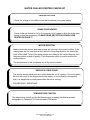
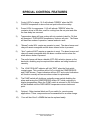
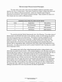
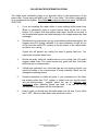
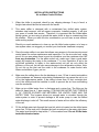
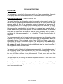
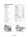
INSTALLATION, OPERATION & MAINTENANCE
OWNERS MANUAL
Dimplex Thermal Solutions
Schreiber 400AC Chiller
TABLE OF CONTENTS
Model ………………………………………………………………………………………………
1
Caution ………………………………………………………………………………………….…
2
Starting Check List ……………………………………………………………………………….
3
Wiring Diagram ……………………………………………………………………………………
5
Setting Solid State Controls & Solid State Control Panel……….………………………….….
6
Chilled Water Distribution Piping ………………………………………………………………..
8
Installation Instructions …………………………………………………………………………..
9
Special Instructions ………………………………………………………………………………
11
Fan Motors ………………………………………………………………………………………..
14
Water Pump ………………………………………………………………………………………
15
Refrigeration System …………………………………………………………………………….. 19
Service Bulletin …………………………………………………………………………………..
20
Crank Case Heaters ……………………………………………………………………………
23
Maintenance Information ………………………………………………………………………...
24
Trouble Shooting – Part I ………………………………………………………………………... 25
Trouble Shooting – Part II ……………………………………………………………………….. 26
Chiller Parts Identification ……………………………………………………………………….
27
Parts ………………………………………………………………………………………………
28
Limited Warranty ……………………………………………..…………………………………... 29
Special Feature(s)
Appendix
www.dimplexthermalsolutions.com
Phone: 800-968-5665
www.dimplexthermalsolutions.com
Phone: 800-968-5665
ELECTRICALJ
HAZARDS
1) TURNOFF MAIN POWERDISCONNECT
SWITCHON THIS MACHINE
BEFOREATTEMPTING
TO SERVICETHIS EQUIPMENT.
2) THIS MACHINEIS PORTABLE.DISCONNECT
ALL POWERSOURCES
BEFOREREMOVINGCONTROLCOVE
RS.
3) USERIS RESPONSIBLEFORLOSSOF (OR FAILURETO USEAND
MAINTAIN) ANTI-HAZARD PROTECTIVECOVERSFOR ELECTRICAL
EQUIPMENT AS FURNISHED BY THE MANUFACTUREROF THIS
MACHINE.
4) SHOULDYOUFIND IT NECESSARY
TO MAKEANY REPAIRSTO THE
REFRIGERATION,
BECAUSEREPAIRCAN BE HAZARDOUS,READTHE
UNIT MANUALUNDERREFRIGERATION,
OR CALLTHE MANUFACTURER
AND SELLER. PLEASENOTETHE DANGEROF OVERCHARGING
THE
REFRIGERATION
SYSTEM.
Failure to read and observe above precautionary warnings are serious
offenses under Public Law 91-596. All employees are hereby notified
that the employer (and owner of this equipment) under OSHA must
take immediate disciplinary action up to and including dismissal for
failure to read and comply with this notice.
To Comply With OSHA, All Warning Signs Must Not Be Removed From This
www.dimplexthermalsolutions.com
Phone: 800-968-5665
Water Chilling
Equipment
WATER CHILLER STARTING CHECKLIST
PROPER VOLTAGE
Check the voltage on the chiller to see that it matches your power supply.
CRANK CASE HEATER
Power to the unit should be on for 3 hours prior to full usage to allow the crank case
heater to heat the compressor. PLEASE READ SECTION ON CRANK CASE
HEATER ON PAGE 17.
MOTOR ROTATION
Make sure the fan motors and water pumps are running in the correct rotation. If the
water pumps run for more than a short period in the wrong direction, the seal might
back off the shaft. To test if the water pumps are rotating in the correct direction, turn
the pump switch on and off quickly. The compressor switch is used to test the fan
motors rotation.
The compressors to this unit always run in the correct rotation.
SERVICE ACCESS PANEL
The service access panel must be in place when the unit is running. If it is not in place,
the unit will cut off on the high-pressure limit switch, or be inefficient in its capacity.
Also, it is dangerous to install panels while the unit is running.
PLEASE READ - IMPORTANT
TEMPERATURE CONTROL
The temperature control and the dial thermometer is reading the discharge water
temperature in Fahrenheit. All controls read in Fahrenheit.
3
www.dimplexthermalsolutions.com
Phone: 800-968-5665
CONT. WATER CHILLER STARTING CHECKLIST
ELECTRIC – POWER
A good test to make sure power is off to the unit is to turn on the water pump switch. If
power is on, the light on this pump will be on. We recommend you take caution in all
judgments about the power being on. The best test to find if the power is on is to use a
voltmeter. Please Note: A single-phase condition can cause a pilot light to be out and still
have voltage to the unit.
TESTING STANDARDS
All components on the chiller meet UL's standards. The system is tested under 250
pounds of pressure. All motors have internal overload protection except where
noted.
ANTIFREEZE
Keep the water tank filled at the proper level. Add antifreeze if you are going to operate
the unit at 380 F or lower.
DEIONIZED WATER
DO NOT USE DEIONIZED WATER IN THE TANK. Deionized water will cause
damage to the copper evaporator.
TANK FILL
Use the 2” Top Fill located on top of the unit to fill the chiller.
www.dimplexthermalsolutions.com
Phone: 800-968-5665
24V
RED
RED
L3
L2
L1
BLACK
Black
T1
T3
RET U RN
1C
+ - + -
T1
T3
T3
RED
T1
BLACK
Pressure Swich Conn.
T2
Pressure Switch Conn.
Float - Low Level Cutout
TC (-)
TC (+)
TC (-)
TC (+)
Pre Low Level Warning
Pump Contactor
Comp Contactor
24 Vac (+)
24 Vac (-)
Terminal Block Connections
R ed
T2
Ye llo w
T2
Y ellow
T1
ALARM
4
2 TIME
1 DELAY
0
TC INPUTS
D ISC H AR GE
T3
24 VAC
G round
Low Lev
Pum p
T2
Comp 1
T2
NC
CO M
NO
T1
Black
1W
Temp. Probes
T3
FLOAT - NO
White / Black
Note: Water cooled units
are not equipped
with FAN motors
Water Pump Starter
Coil
PURPLE
WHITE
1W
BLUE
BF
White
Pink
RED
RED
Compressor 1 Starter Coil
BLUE
LP Switch
Orange
1C
HP Switch
RED
LLVS
1S
RED
Purple / White
Orange
Dry Contacts (NO)
Yellow
W hite / Black
Black
Ret. Temp Senor
Yellow
Red
Disch. Tem p Senor
Yellow
Pink
White
Purple
Black
Power Supply
Red
RED
PRE - LOW LEVEL
WARNING LIGHT
FLOAT
NC
Models:
Voltage
LLSV - Liquid Line Solenoid Valve
Mydoc/electrical/newelectrical/singlestagemedical/single stage Philips 4 Ton
BF - Back Flow
Kit Solenoid Valve
www.dimplexthermalsolutions.com
Phone: 800-968-5665
200 -500 AC /WC
230-460
Phase: 3
PHILIPS 4 TON
Marks:
Type:: Air Cooled/Water
Cooled
Cooled
Notes:
All motors have internal overload protection unless otherwise shown
On all connections: L1 - Blue L2 - Black L3- Red
Schreiber Engineering
(562)-926-3855
12111 Park St. Cerritos, CA 90703
(562)-926-0969 Fax
Options:
MEDICAL CHILLER WITH HEAD
PRESSURE CONTROL VALVE
Low Ambient
Electronic Controls
Back Flow kits
SPECIAL CONTROL FEATURES
1)
Control LED’s for stage 1 & 2 will indicate "GREEN" when the DISCHARGE temperature is above their set point without time delay.
2)
Power LED's for compressor 1 & 2 will indicate "GREEN" when the
contactor driver is ON after a call for cooling from the set point and after
the time-delay has occurred.
3)
Temperature alarm will have a relay with dry contacts (rated for 7A) that
will energize if DISCHARGE temperature is above set point. The Alarm
will have two modes of operation, manual and auto reset.
4)
"Manual" mode WILL require an operator to reset. The alarm buzzer and
relay will remain energized and the alarm silence button is pressed.
5)
"Auto" mode will NOT require an operator to reset. The alarm buzzer and
relay will remain energized while the alarm condition exists unless the
alarm silence button is pressed.
6)
The audio buzzer will have a disable (OFF-ON) selection jumper on the
back side, disabling may be required when alarms are being monitored
remotely.
7)
The LOW COOLANT indicator will light "RED" when the float switch
contacts open. This condition will turn off or inhibit the COMPRESSOR
and PUMP drivers. Power indicators will turn OFF and control indications
will function normally will resume when coolant is replenished.
8)
The PUMP switch will double as a standby power switch disabling the
alarm and turning the COMPRESSOR drivers OFF while continuing to
display temperatures When the PUMP switch is returned to ON, the alarm
will be disabled until the DISCHARGE temperature returns below setpoint.
9)
Optional - Relay terminal block and 3 pos switch for remote power
applications These components can be assembled for an extra charge.
10)
Fuse will be of the 5 x 20MM that can be replaced easily.
www.dimplexthermalsolutions.com
Phone: 800-968-5665
SETTING SOLID STATE CONTROL
This unit has a solid-state control that controls the temperature on the refrigeration
system. After the unit is wired to the proper voltage the control temperature and high
temperature alarm can be set.
1.
On the front of this control is the temperature display, to set the temperature
press and hold button #2 while turning the set point screw above button #2. The
temperature display will indicate the set temperature as you turn the set point
screw.
2.
To set the high temperature alarm press and hold button #3 while turning the set
point screw above button #3. The temperature display will indicate the set
temperature for the high temperature alarm as you turn the set point screw.
We suggest you keep the differential, between the temperature and the alarm, at 50 F
then set the alarm temperature at 60o F. The alarm will sound at 60o F.
3.
Press button #4 to turn the alarm off if necessary. After the cause of the alarm
has been found, be sure to turn the alarm back on.
4
Alarm Feature. – The high temperature alarm does not function when the
compressor and water pump switch is in the “off” position., for example, during
the night shut down. When the compressor and water pump switch is turned on
in the morning, the alarm will not sound even if the water temperature is above
the set point, however, the red fault light (number four on page 8) will remain on
until a temperature below the set point is reached. The audible alarm will sound
again unless the water temperature rises again above the set point.
CHECKING TEMPERATURE SET POINTS
To check temperature set points just press #2 for compressor and #3 for alarm set
points.
CAUTION
Check low voltage, this is a 24 Volt system. Be sure you check the 24 Volt circuit at the
main panel and remote panel.
REMOTE WIRING – SOLID STATE CONTROL
This unit is designed for remote control. We have supplied the wire to connect the main
water chiller control panel to the remote panel. Make sure you connect the remote wire
colors to match the terminal block. in the electrical enclosure. There is a diagram insert
with colors to match the numbers on the terminal block.. The thermocouple wire is a
special wire and cannot be spliced to other types of wiring. The main control panel has
pilot
www.dimplexthermalsolutions.com
Phone: 800-968-5665
www.dimplexthermalsolutions.com
Phone: 800-968-5665
www.dimplexthermalsolutions.com
Phone: 800-968-5665
CHILLED WATER DISTRIBUTION PIPING
The chilled water distribution piping is an important factor in the performance of the
water chiller. Proper piping will add to the LIFE of your chiller. This chiller is designed to
be a containment free system. The chilled water piping should be the same. NO BLACK
IRON PIPE.
1.
If you are installing this water chiller to some existing chiller water lines
(Black or galvanized) there is a good chance there will be rust in this
system. If you cannot flush this system clean then it should not be used. A
rust contaminated system will cause damage to the copper evaporator heat
exchanger.
2.
Should this be a new system and you are installing chilled water piping. We
suggest using PVC piping if allowed. It is a poor conductor of heat, so you
do not loose as much BTU capacity in the movement of the chilled water
and there is no rusting.
Copper line will prevent any rusting but there is greater heat loss. You
might want to insulate these li nes.
3.
Should the water chiller be installed next to your cooling load. We would
suggest rubber hose. This would prevent any great heat loss. And there
would also be no contamination.
4.
If black pipe, galvanize, iron, and steel pipe are your piping of choice, you
should be aware of the corrosiveness of these materials. Black Iron will
damage the watering system.
5.
Female connections to chiller are brass. If your connections to the chiller
are anything other than, PVC, copper, or rubber hose you should consult
with your local plumbing
supplier about the use of dielectric pipe
connections when dissimilar metals are used. If we can be of any
assistance with this please call the manufacturer.
6.
Keep in mind you should keep all chilled water lines full size. If your chiller
has 1" NPT, then the chilled water lines should be no less.
8
www.dimplexthermalsolutions.com
Phone: 800-968-5665
INSTALLATION INSTRUCTIONS
Air or Water Cooled Chillers
1.
When the chiller is received, check for any shipping damage. If any is found, a
freight claim should be filed at once with the carrier.
2.
This water chiller is designed with a contaminant free chilled water system,
stainless steel reservoir, and all copper evaporator. Installed properly, it will give
you years of trouble free service. Therefore, it is important that the chilled water
piping system you are using to plumb this water chiller is also as contaminant free
as possible. When you take this into consideration you will have a most efficient
water cooling system
Should you need assistance to clean up an old chilled water system or to keep a
new system clean, we suggest you contact your local water treatment company.
3.
Place the water chiller in an area that allows easy access to the service doors and
control panel for routine maintenance and inspection. For the air-cooled unit, make
sure it is in an area where there is good air circulation over the condenser inlet, 24"
from any obstruction. For the water-cooled unit, make sure it has a good water
supply by keeping the piping to the condenser 1" in size. Restriction of air to the
air-cooled condenser or water to the water-cooled unit will not only affect the
efficiency of the unit, but will also cause damage to the refrigeration system. Note:
Do not mix up the inlet and the outlet to the condenser on water-cooled units.
Water-cooled takes 3 gpm, per ton.
4.
Make sure the ceiling above the fan discharge is over 12 feet to avoid recirculation
of the condenser air, because recirculating condensed air can cause the unit to cut
off on the high-pressure switch. If the ceiling is lower than 12 feet, a straight duct
out of the ceiling should be installed in order to prevent the air from recirculating
over the condenser.
5.
Make up two chilled water lines, a discharge and a return line. The fitting on the
chiller for these lines is 1" pipe coupling. IT SHOULD BE NOTED THAT THERE IS
A 1/4" COPPER BY-PASS LINE BETWEEN THE WATER PUMP AND THE
WATER TANK. This by-pass allows just enough water to circulate through the
water system in order to prevent damage to the water pump in case the chilled
water discharge is shut off. This small amount of water will not affect the efficiency
of the unit.
6.
Fill the chilled water tank through the hose bib, which is located on the chilled water
return line. Fill the tank until it reaches the level as marked on the water sight glass.
The water level should be kept within 1" of the marked level. Do not fill the water
tank with deionized water.
9
www.dimplexthermalsolutions.com
Phone: 800-968-5665
7.
Check the voltage on the chiller to see that it matches your supply. When applying
power to the water pump (by turning the manual switch on), make sure all the
switches on the control panel are in the "off" position. It is necessary to check the
rotation of the water pump. The motors on all pumps have an internal overload
protection.
8.
Power to the unit should be on for 3 hours prior to full usage to allow the crank
case heater to heat the compressor. PLEASE READ SECTION ON CRANK CASE
HEATER ON PAGE 18.
9.
The water pump manual switch controls the operation of the water pump. After
checking the rotation of the water pump. PLEASE NOTE when the water pump is
turning the proper rotation. The water pump switch must be on in order to check
rotation of fan motor. The refrigeration system will not run unless the water pump
switch is in the on position. Set the temperature controller to the desired
temperature. If the temperature is set below 36° F, antifreeze must be added to the
water supply tank. Use non-automotive antifreeze which can be added through the
overflow pipe. Never add more antifreeze than necessary, since it is a poor
conductor of heat the cooling capacity of the chiller will be reduced.
10. With the temperature controller set, the compressor can be turned on by the
manual switch. The refrigeration system is now running. It should be noted that
there could be a two to three degree difference between the temperature control
setting and the dial thermometer. Use the dial thermometer as a guide. Once set,
the temperature controller will control the temperature of the water automatically.
10
www.dimplexthermalsolutions.com
Phone: 800-968-5665
WATER PUMP
SPECIAL INSTRUCTIONS
The water pump is controlled by the manual switch for off and on operations. The motor
on this pump has a built-in overload protection, as do all the motors in our system.
ELECTRICAL CONTROLS - Control Circuit 24 Volts
The control circuit for the refrigeration system has several controls wired in series. First
are the high and low-pressure switches that are mounted in the control panel. The highpressure switch will shut off the refrigeration system in the event the pressure is too
high. High pressure can be caused by the condenser becoming restricted, by foreign
material on the outside surface of the condenser, or if the fan motor is not running. If the
high-pressure limit switch should cut out, there is a manual reset switch, which is
located at the control panel on the right side. In order to reset this switch, the disconnect
switch and the switch must be turned off and the control panel door must be open. If
and when the high-pressure switch is off, check the "Trouble Shooting" cha rt for
diagnosis.
The low-pressure switch will cut out at any time the pressure in the refrigeration system
is below 25 psi. Low psi can be caused by a freeze up in the water tank, a leak in the
refrigeration system, if the system is low on Freon (R-22), or if there is any sort of
restriction in the system. If the switch cuts out, it will automatically reset. Never try to
adjust the high and low-pressure switches or by-pass them, or serious damage to
the system will result. Adjustment should only be made after the internal pressure of
the refrigeration system has been read.
The second control of the circuit is the temperature controller. It controls the cycling of
the refrigeration system. Once this control is set, it will control the cycling of the unit
automatically. Do not set it below freezing unless the proper amount of antifreeze is put
into the unit. Since antifreeze is a poor conductor of heat, never add more than
necessary.
The third control on the circuit is the manual compressor switch. It is only used to turn
the refrigeration system on or off.
The fourth part on the circuit is the overload protection on the compressor. It will open if
the unit becomes low on refrigeration or if the improper voltage is used. This part of the
circuit is an automatic reset.
11
www.dimplexthermalsolutions.com
Phone: 800-968-5665
CHILLED WATER CIRCUIT
The chilled water is pumped from the chiller's water tank to the discharge outlet of the
chiller. Then from the discharge outlet, the water travels to the object to be cooled,
through the heat exchanger, and returns through the chillers return line into the water
tank. Be sure to keep all lines full size (1"). If the size of the lines are reduced, then the
flow of water will be restricted, and thus resulting in improper chilling.
12
www.dimplexthermalsolutions.com
Phone: 800-968-5665
REFRIGERATION SYSTEM:
The refrigeration system is a medium temperature system with a range from 35°F to
70°F. This is the most efficient range. If temperatures below or above this range are
required, they should be discussed with our engineering department. The refrigeration
system also includes a hermetically sealed refrigeration system and all parts, except the
evaporator coil, are standard to the refrigeration industry. The evaporator coil is installed
in a stainless steel tank and the tank on each unit has a large area. This large area
allows better control of water temperature and causes the water flow not to be
restricted, resulting in better water circulation. Any repairs to the refrigeration system
should be done by a qualified refrigeration company. Schreiber Engineering will always
have a service engineer available to answer any questions regarding chiller service.
This unit has a service valve on the suction and discharge line. The suction line has its
valve on the suction line. The high pressure or discharge service line is on the receiver.
This unit is charged with R-22. DO NOT OVERCHARGE because this will cause
damage to the compressor. The refrigeration sight glass is fuzzy until the unit reaches
its proper temperature.
MAINTAINING THE CHILLER:
Very little maintenance is required on this unit. It might be necessary to clean out the
heat exchanger located within the water tank, only depending on the condition of the
water used in the chilled water circuit. It might also be necessary to blow out the
condenser from time to time, depending on the environment of the installed unit. Finally,
the water-cooled condenser needs to be flushed out once in a while. The frequency of
this process depends on the condition of the condenser's water supply.
13
www.dimplexthermalsolutions.com
Phone: 800-968-5665
FAN MOTOR SPECIFICATIONS
Refer to your model number & voltage
Model #
H.P.
Voltage
50AC
100AC
100AC
150AC
200AC
300AC
400AC
500AC
600AC
750AC
800AC
1001AC
1000AC
1250AC
1500AC
2000AC
2500AC
3000AC
1/4 Hp
1/4 Hp
1/4 Hp
1/4 Hp
1/2 Hp
1/2 Hp
1/2 Hp
1/2 Hp
1/2 Hp
1/2 Hp
1/2 Hp
1/2 Hp
1/2 Hp
1/2 Hp
1 Hp
1 Hp
1 Hp
1 Hp
115/208/230-1 Ph.
115/208/230-1 Ph.
460-3 Ph.
208/230/460-3 Ph.
208/230/460-3 Ph.
208/230/460-3 Ph.
208/230/460-3 Ph.
208/230/460-3 Ph.
208/230/460-3 Ph.
208/230/460-3 Ph.
208/230/460-3 Ph.
208/230/460-3 Ph.
208/230/460-3 Ph.
208/230/460-3 Ph.
208/230/460-3 Ph.
208/230/460-3 Ph.
230/460-3 Ph.
460-3 Ph.
Hz R.P.M. Overload Frame Mounting Rotation
60
60
60
60
60
60
60
60
60
60
60
60
60
60
60
60
60
60
1725
1725
1140
1140
1140
1140
1140
1140
1140
1140
1140
1140
1140
1140
1725
1725
1725
1725
Automatic
Automatic
Automatic
Automatic
Automatic
Automatic
Automatic
Automatic
Automatic
Automatic
Automatic
Automatic
Automatic
Automatic
Automatic
Automatic
Automatic
Automatic
G48
G48
L48
L48
F56
F56
F56
F56
F56
F56
F56
F56
F56
F56
E56
E56
E56
E56
Rigid O.D.P.
Rigid O.D.P.
Rigid O.D.P.
Rigid O.D.P.
Rigid O.D.P.
Rigid O.D.P.
Rigid O.D.P.
Rigid O.D.P.
Rigid O.D.P.
Rigid O.D.P.
Rigid O.D.P.
Rigid O.D.P.
Rigid O.D.P.
Rigid O.D.P.
Rigid O.D.P.
Rigid O.D.P.
Rigid O.D.P.
Rigid O.D.P.
CW
CW
CW
CW
CW
CW
CW
CW
CW
CW
CW
CW
CW
CW
CW
CW
CW
CW
Blade
QTY.
14" x 16 Pitch
16" x 26 Pitch
16" x 26 Pitch
16" x 26 Pitch
18" x 24 Pitch
18" x 24 Pitch
18" x 24 Pitch
18" x 24 Pitch
18" x 24 Pitch
18" x 24 Pitch
18" x 24 Pitch
18" x 24 Pitch
18" x 24 Pitch
18" x 24 Pitch
24" x 16 Pitch
24" x 16 Pitch
24" x 16 Pitch
24" x 16 Pitch
1
1
1
1
1
1
1
1
2
2
2
2
2
2
2
2
3
3
SAFETY:
Avoid personal injury or equipment damage by disconnecting electrical power before working on the motor(s).
Do not remove the door(s) while the unit is connected to electrical power.
MAINTENANCE:
1. There are no lubrication points; therefore, no lubrication is necessary
2. Make sure the blade runs in the correct direction.
3. Clean the outside of the motor as necessary.
14
www.dimplexthermalsolutions.com
Phone: 800-968-5665
14
Installation, Operation and
Maintenance Instructions.
Model NPE/NPE-F
DESCRIPTION & SPECIFICATIONS:
The models NPE (close-coupled) and NPE-F (framemounted) are end suction, single stage centrifugal
pumps for general liquid transfer service, booster
applications, etc. Liquid-end construction is all AISI Type
304 stainless steel, stamped and welded. Impellers are
fully enclosed, non-trimable to immediate diameters.
Casings are fitted with a diffuser for efficiency and for
negligible radial shaft loading.
Close-coupled units have NEMA 48J or 56J
motors with C-face mounting and threaded shaft
extension. Frame-mounted units can be coupled to
motors through a spacer coupling, or belt driven.
1. Important
1.1. Inspect unit for damage. Report any damage to
carrier/dealer immediately.
1.2. Electrical supply must be a separate branch circuit
with fuses or circuit breakers, wire sizes, etc., per
National and local electrical codes. Install an all-leg
disconnect switch near pump.
CAUTION
Always disconnect electrical power when handling pump
of controls.
1.3. Motors must be wired for proper voltage. Motor
wiring diagram is on motor nameplate. Wire size must
limit maximum voltage drop to 10% of nameplate voltage
at motor terminals, or motor life and pump performance
will be lowered.
1.4. Always use horsepower-rated switches, contactor
and starters.
1.5. Motor Protection
1.5.1. Single-phase: Thermal protection for
single-phase units is sometimes built in (check
nameplate). If no built-in protection is provided,
use a contactor with a proper overload. Fusing
is permissible.
1.5.2. Three-phase: Provide three-leg protection
with properly sized magnetic starter and thermal
overloads.
1.6. Maximum Operating Limits:
Liquid Temperature: 212F (100C) with standard seal.
250F (120C) with optional high
temp seal.
Pressure:
75 PSI.
Starts Per Hour:
20, evenly distributed.
1.7 Regular inspection and maintenance will increase
service life. Base schedule on operating time. Refer to
section 8.
2. Installation
2.1. General
2.1.1. Locate pump as near liquid source as
possible (below level of liquid for automatic
operation).
2.1.2. Protect from freezing or flooding.
2.1.3. Allow adequate space for servicing and
ventilation.
2.1.4. All piping must be supported
independently of the pump, and must “line-up”
naturally.
CAUTION
Never draw piping into place by forcing the pump suction
and discharge connections.
2.1.5. Avoid unnecessary fittings. Select sizes to
keep friction losses to a minimum.
2.2. Close-Coupled Units:
2.2.1. Units may be installed horizontally,
inclined or vertically.
CAUTION
Do not install with motor below pump. Any leakage or
condensation will affect the motor.
2.2.2. Foundation must be flat and substantial to
eliminate strain when tightening bolts. Use rubber
mounts to minimize noise and vibration.
2.2.3. Tighten motor hold-down bolts before connecting
piping to pump.
2.3. Frame-Mounted Units:
2.3.1. Bedplate must be grouted to a foundation with
solid footing. Refer to Fig. 1.
15
www.dimplexthermalsolutions.com
Phone: 800-968-5665
2.3.2. Place unit in position on wedges located at
four points (two below approximate center of driver
and two below approximate center of pump). Adjust
wedges to level unit. Level or plumb suction and
discharge flanges.
2.3.3. Make sure bedplate is not distorted and final
coupling alignment can be made within the limits of
movement of motor and by shimming, if necessary.
2.3.4. Tighten foundation bolts finger tight and build
dam around foundation. Pour grout under bedplate
making sure the areas under pump and motor feet
are solid. Allow grout to harden 48 hours before
fully tightening foundation bolts.
2.3.5. Tighten pump and motor hold-down bolts
before connecting the piping to pump.
4. Discharge Piping:
4.1. Arrangement must include a check valve located
between a gate valve and the pump. The gate valve is
for regulation of capacity, or for inspection of the pump
or check valve.
4.2. If an increaser is required, place between check
valve and pump.
4.3. Use 3 -4 wraps of Teflon tape to seal threaded
connections.
5. Motor-To-Pump Shaft Alignment:
5.1. Close-coupled Units:
5.1.1. No field alignment necessary.
5.2. Frame-Mounted Units:
5.2.1. Even though the pump-motor unit may
have a factory alignment, this could be
disturbed in transit and must be checked prior
to running.
3. Suction Piping:
3.1. Low static suction lift and short, direct, suction piping is
desired. For suction lift over 10 feet and liquid temperatures
over 120 F, consult pump performance curve for Net Positive
Suction Head Required.
3.2. Suction pipe must be as large as the suction connection
of the pump. Smaller size will degrade performance.
3.3. If larger pipe is required, and eccentric pipe reducer (with
straight side up) must be installed at the pump.
3.4. Installation with pump below source of supply:
3.4.1. Install full flow isolation valve in piping for
inspection and maintenance.
CAUTION
Do not us e suction isolation valve to throttle pump.
3.5. Installation with pump above source of supply:
3.5.1. Avoid air pockets. No part of piping should be
higher than pump suction connection. Slope piping
upward from liquid source.
3.5.2. All joints must be airtight.
3.5.3. Foot valve to be used only if necessary for
priming, or to hold prime on intermittent service.
3.5.4. Suction strainer open area must be at least
triple the pipe area.
3.6. Size of the inlet from liquid source and minimum
submergence over inlet, must be sufficient to prevent air from
entering pump through vortexing. See figs. 2-5.
5.2.2 Tighten all hold-down bolts before
checking the alignment.
5.2.3. If re-alignment is necessary, always
move the motor. Shim is required.
5.2.4. Parallel misalignment – shafts with axis
parallel but not concentric. Place a dial
indicator on one hub and rotate this hub 360°
while taking readings on the outside diameter
of the other hub. Parallel alignment occurs
when Total indicator reading is .005”, or less.
5.2.5. Angular misalignment – shafts with axiz
parallel but not concentric. Place dial
indicator on one hub and rotate this hub 360°
while taking readings on the face of the other
hub. Angular alignment is achieved when
Total Indicator Reading is .005”, or less.
5.2.6. Final alignment is achieved when
parallel and angular requirements are
satisfied with motor hold-down bolts tight.
CAUTION
Always recheck both alignments after making any
adjustment.
6. Rotation:
6.1. Correct rotation is right-hand (clockwise when
viewed from the motor end). Switch power on and off
quickly. Observe shaft rotation. To change rotation:
16
www.dimplexthermalsolutions.com
Phone: 800-968-5665
6.1.1. Single-phase motor: Non-reversible.
6.1.2. Three-phase motor: Interchange any two
power supply leads.
9.4.4. Remove impeller (101) by turning counterclockwise when looking at the front of the pump.
Protect hand with rag or glove.
CAUTION
Failure to remove impeller in a counter-clockwise
direction may damage threading on the impeller, shaft
or both.
7. Operation:
7.1. Before starting, pump must be primed (free of air
and suction pipe full of liquid) and discharge valve
partially open.
CAUTION
Pumped liquid provides lubrication. If pump is run
dry, rotating parts will seize and mechanical seal will
be damaged. Do not operate at or near zero flow.
Energy imparted to the liquid is converted into heat.
Liquid may flash to vapor. Rotating parts require
liquid to prevent scoring or seizing.
7.2. Make complete check after unit is run under
operating conditions and temperature has stabilized.
Check fro expansion of piping. On frame-mounted units
coupling alignment may have changed due to the
temperature differential between pump and motor.
Recheck alignment.
9.4.5. With two pry bars 180° apart and inserted
between the seal housing (184) and the motor
adapter (108), carefully separated the two parts.
The mechanical seal rotary unit (383) should
come off the shaft with the seal housing.
9.4.6. Push out the mechanical seal stationary
seat from the motor side of the seal housing.
9.5. Disassembly of Bearing Frame:
9.5.1. Remove bearing cover (109).
9.5.2. Remove shaft assembly from frame (228).
9.5.3. Remove lip seals (138 & 139) from bearing
frame and bearing cover if worn and are being
replaced.
9.5.4. Use bearing puller or arbor press to remove
all ball bearing. (112 & 168).
8. Maintenance:
10. Reassembly:
8.1. Close-coupled Unit. Ball bearings are located in and
are part of the motor. They are permanently lubricated.
No greasing required.
8.2. Frame-Mounted Units:
8.2.1. Bearing frame should be re-greased
every 2,000 hours or three month interval,
whichever occurs first. Use a #2 sodium or
lithium based grease. Fill until grease comes out
of relief fittings, or lip seals, then wipe off
excess.
8.2.2. Follow motor and coupling manufacturers’
lubrication instructions.
8.2.3. Alignment must be rechecked after any
maintenance work involving and disturbance of
the unit.
10.1. All parts should be cleaned before assembly.
10.2. Refer to parts list to identify required replacement
items. Specify pump index or catalog number when
ordering parts.
10.3. Reassembly is the reverse of disassembly.
10.4. Observe the following when reassembling the bearing
frame:
10.4.1. Replace lip seals if worn or damaged.
10.4.2. Replace ball bearings if loose, rough or
noisy when rotated.
10.4.3. Check shaft for runout. Maximum
permissible is .002” T.I.P.
10.5. Observe the following when reassembling the liquidend:
10.5.1. All mechanical seal components must be
in good condition or leakage may result.
Replacement of complete seal assembly,
whenever seal has been removed, is a good
standard practice.
10.5.2. Inspect casing O-ring (513) and replace if
damaged. This o-ring may be lubricated with
petroleum jelly to ease assembly.
10.5.3. Inspect guidevane O-ring (349) and
replace if worn.
CAUTION
Do not lubricate guidevane O-ring (349). Insure it is not
pinched by the impeller on reassembly.
9. Disassembly:
Complete disassembly of the product will be described.
Proceed only as far as required to perform the
maintenance work needed.
9.1. Turn off Power.
9.2. Drain system. Flush if necessary.
9.3. Close-Coupled Units: Remove motor hold-down
bolts. Frame-Mounted Units: Remove coupling, spacer,
coupling, spacer, coupling guard and frame hold-down
bolts.
9.4. Disassembly of Liquid End:
9.4.1. Remove casing bolts (370).
9.4.2. Remove back pull-out assembly from
casing (100).
9.4.3. Remove impeller locknut (304).
10.6. Check reassembled unit for binding. Correct as
required.
10.7. Tighten casing bolts in a star pattern to prevent Oring binding.
CAUTION
Do not insert screwdriver between impeller vanes to
prevent rotation of close-coupled units. Remove cap
at opposite end of motor. A screwdriver slot or a pair
of flats will be exposed. Using them will prevent
impeller damage.
www.dimplexthermalsolutions.com
Phone: 800-968-5665
17
18
www.dimplexthermalsolutions.com
Phone: 800-968-5665
WARNING
Overcharging a refrigeration or air conditioning system can be dangerous.
****
If a system refrigerant overcharge is sufficient to immerse the major parts of the motor
and compressor in liquid refrigerant, a situation has been created which, when followed
by unusual circumstances can lead to compressor housing seam separation or rupture.
The sequence of circumstances which can lead to compressor housing seam
separation or rupture may occur in the following manner:
(a)
The system overcharge immerses the compressor motor, piston,
connecting rods, cylinder, etc., in liquid refrigerant, thereby effectively
forming a hydraulic block preventing the compressor from starting. This
condition is known as locked rotor.
(b)
Electric current continues to flow through the compressor motor windings
that become, in effect, electric resistance heaters. The heat produced
begins to vaporize the excessive refrigerant liquid overcharge, causing a
rapid increase in system pressure.
(c)
If the system compressor protective devices fail for any reason prior to or
during this locked rotor heating cycle, or cycles, liquid refrigerant may be
vaporized sufficiently fast enough to raise the pressure within the system to
extremes far in excess of the housing or weld seam design limits.
(d)
In some instances where the amount of refrigerant overcharge is critical in
proportion to the system internal volume, the pressure reached can cause
a compressor housing seam separation or rupture, which can be
hazardous.
The remedy to eliminate this exceedingly rare but potential hazard is to use correct
refrigerant charging amounts and techniques.
Tecumseh Products Company urges that all individuals responsible for training,
teaching, or advising installation mechanics and service personnel, must emphasize
proper charging techniques and strict adherence to limiting refrigerant charge amounts
to those specifically recommended by the manufacturer of the refrigeration, air
conditioning, or heat pump system.
19
www.dimplexthermalsolutions.com
Phone: 800-968-5665
SERVICE BULLETIN
HERMETIC COMPRESSOR ELECTRICAL TERMINAL VENTING
CAN BE DANGEROUS
****
When the insulating material, which supports a hermetic compressor electrical terminal,
suddenly disintegrates due to physical abuse or as a result of an electrical short
between the terminal and the compressor housing, the terminal may be expelled,
venting the vaporous and liquid contents of the compressor housing and system.
If the hermetic compressor terminal PROTECTIVE COVER is not properly in place with
its weatherproofing gasket (if required) and bale strap fastening device secured, there is
a remote possibility if a terminal vents, that the vaporous and liquid discharge can be
ignited, spouting flames several feet, causing potentially severe or fatal injury to anyone
in its path.
The discharge from a venting terminal can be ignited external to the compressor if the
terminal PROTECTIVE COVER is not properly in place and if the discharge impinges
on a sufficient heat source such as, but not limited to, an open flame, electric heater, or
an electrical spark.
Ignition of the discharge can also occur at the venting terminal or inside the motorcompressor enclosure, if there is sufficient contaminant air present in the system and an
electrical arc occurs as the terminal vents.
Ignition cannot occur at the venting terminal without the presence of contaminant air,
and cannot occur externally from the venting terminal without the presence of an
external ignition source.
It is, therefore, essential that any air in a refrigeration, air conditioning, or heat pump
system be completely removed when the system is manufactured - when the system is
installed - and whenever the system is field processed as a result of field service. Field
service includes, but is not limited to, leak repairs or compressor replacement.
Eliminating air within the system prevents ignition at, or in, the hermetic compressor if a
terminal should vent, thereby reducing the hazard potential.
To reduce the possibility of external ignition, all open flame, electrical power, and other
heat sources should be extinguished or turned off prior to servicing a system.
Before using a soldering or welding torch to remove or repair tubing, make sure all the
system refrigerant charge has safely been released.
A venting terminal presents no danger to servicing personnel or anyone else in the
vicinity if the compressor terminal PROTECTIVE COVER is properly in place as shown
on Tecumseh Products Company drawings and diagrams using the parts as shown on
Tecumseh Products Company bills of material.
20
www.dimplexthermalsolutions.com
Phone: 800-968-5665
Hermetic compressors can be properly serviced without unnecessarily removing the
terminal PROTECTIVE COVER by adhering to the following service procedures:
1.
If the branch circuit, short circuit, and ground fault protective device, i.e., fuse or
circuit breaker, is open, this is a strong indication that an electrical problem exists
and must be found and corrected.
The circuit protective device rating must first be checked as required by the
National Electrical Code, and its maximum rating should coincide with that marked
on the equipment nameplate and/or on the unit wiring diagram and/or instructions.
This breaker or fuse rating should be as low as practical. A rule of thumb is 175%
times the motor-compressor RLA (FLA on older units) as shown on the unit
nameplate.
It is acceptable to first replace the fuse or reset the circuit breaker ONE TIME to
determine if it was just a nuisance opening. WARNING! The terminal
PROTECTIVE COVER must be securely in place.
2.
If the fuse or circuit breaker again opens, DO NOT continue to replace or reset, as
the equipment obviously has an electrical problem. CAUTION! Continual resetting
may cause the terminal to vent.
3.
DISCONNECT all power to the unit, making sure all power legs are open.
4.
Without removing the terminal PROTECTIVE COVER, disconnect the three leads
going to the compressor terminals at the nearest point to the compressor, and
identify them as Common (C), Start (S), and Run (R). Identification can generally
be made through the unit-wiring diagram. DO NOT disconnect at the compressor
terminals at this time.
5.
With a Megger, Hi-Potential Ground Tester, or other suitable instruments which
puts out a voltage between 300 and 1500 volts, check for a ground separately
between each of the three C, S, & R leads and ground (such as an unpainted tube
on the compressor). Do not use a low voltage output instrument such as a voltohmmeter or other such continuity instruments, as these will not detect a low level
fault (ground).
6.
If a ground is indicated, then carefully remove the compressor terminal
ROTECTIVE COVER and inspect for loose leads or insulation breaks in the lead
wires.
7.
If #6 indicates no visible problem, carefully remove the leads at the compressor
terminals. CAUTION: Damage can occur to the glass embedded terminals at this
point if the leads are not properly removed, which can result in the terminal venting
and hot oil discharging. No ignition, however, can occur if all power is
disconnected and no external ignition source is present.
www.dimplexthermalsolutions.com
21
Phone: 800-968-5665
8.
Repeat #5 testing, carefully checking for ground, directly between each
compressor terminal (C, S, & R) and ground.
9.
If once again a ground is indicated, proceed to properly replace the compressor,
as it has failed and cannot be repaired.
10. It is important to note that a volt-ohmmeter may be used only to check the
resistance and/or continuity of the motor windings. This may be done as follows:
(a)
For internal overload protected motor-compressor, the overload is located
between the common terminal of the compressor and the common motor
lead inside the compressor. If the resistance reading between Common
and Start or Common and Run is open (infinity) and the resistance reading
between Start and Run indicates winding Resistance Values in the
Tecumseh Hermetic Compressor Service Data Book, then the internal
protector is open and time must be allowed for it to reset. Any Common
and Start, Common and Run, and Start and Run resistance reading must
be within the values shown in Tecumseh Hermetic Compressor Service
Data Book.Three phase internal overloads open all three phases.
Therefore, allow time for reset.
(b)
For external overload protected motor-compressors, the continuity of the
overload may be checked. The resistance of all winding may also be
checked, i.e., C-S, C-R, and S-R.
(c)
Any lack of continuity (other than test indicating an open internal protector)
or improper resistance, indicates a faulty or damaged motor and the
compressor must be properly replaced, as it has failed and cannot be
repaired.
If the above indicates no problem with the compressor, then carefully reconnect the
leads to the proper compressor terminals (C, S, & R); correctly replace the terminal
PROTECTIVE COVER, gasket (if required), and the bale strap.
Then proceed to conduct similar ground and continuity test from the three lead
connection points which you previously disconnected, forward toward the incoming
power connections, to find the electrical problem. DO NOT reset the ground fault
protective device until you have located and corrected the problem. Refer to the Unit
Wiring Diagram and Service Manual for the proper procedure and wiring checkout.
The text of step-by-step procedures uses language and symbols which refer to the
electrical supply as single phase. Three-phase equipment should be given equally
cautious consideration when service is necessary.
22
www.dimplexthermalsolutions.com
Phone: 800-968-5665
Again, we want to stress that it is essential that WHENEVER ELECTRIC POWER is
applied to the motor-compressor, the terminal PROTECTIVE COVER must be properly
in place.
Servicing refrigeration and air conditioning systems can be dangerous, and extreme
caution in all respects should be exercised by the personnel servicing such equipment.
The precautions discussed in this bulletin deal only with those dangers associated with
VENTING TERMINALS.
CRANK CASE HEATERS
This unit has a CRANK CASE HEATER on the compressor. It is important to the life of
this compressor that you follow the instructions. This low wattage heater protects the
compressor when it is idle by producing just enough heat to keep the Freon from
accumulating in the compressor. Under certain specific conditions this heater will
prevent the compressor from slugging causing damage to its internal parts.
These Heaters are wired at our factory in such away that allows the heater to be on any
time the disconnect switch on the chiller is on. When you want to turn the water pump or
refrigeration compressor off, you must only use the manual switches on the electrical
enclosure as marked. When you use the disconnect to turn the unit off you kill the
power to the crank case heaters. ONLY use the disconnect to turn off power if you are
going to work on the electrical system.
AN IMPORTANT FACTOR - READ
SPECIAL INSTRUCTIONS FOR CRANK CASE HEATER
When the unit is first received, the power to the chiller should be on for 3 hours. That
means you must at this time have the unit disconnect on. The manual water pump and
refrigeration switches should be off. This will allow the refrigeration compressor to warm
up, driving out the freon (R22) that had migrated to the compressor.
This start up time is necessary if you have all the power off for 12 hours or more. Then
you must allow this same warm up time. It is okay to turn the unit off by the manual
switch only and not the main power. Then you do not need to be concern about a warm
up time.
The crank case heater is HIGH VOLTAGE. But it is only very low wattage. Caution
should be taken when working on the crank case heater to make sure the POWER is
off.
Any question call for more details Schreiber Engineering Corporation 562-926-3855.
23
www.dimplexthermalsolutions.com
Phone: 800-968-5665
MAINTENANCE INFORMATION
1.
There are no lubrication points on the chiller. All motors have permanent
lubrication in the bearings.
2.
The water that is used in the chilled water circuit has no special requirements,
except that deionized water cannot be used. The water should be clean and some
type of water conditioner can be used. Nothing should be used in the chilled water
circuit that could damage the all copper Heat Exchanger. THIS INCLUDES THE
USE OF DEIONIZED WATER.
3.
The air-cooled condenser should be cleaned on a regular basis, depending on the
environment the chiller is installed in.
4.
The water level should be maintained as close to the level as marked on the water
sight glass. You cannot damage the refrigeration system by the water being at a
low level, it will only affect the efficiency of the unit.
5.
Caution: The compressor receivers and water pump could be hot enough to injure
one touching these components.
6.
The dial thermometer is reading the temperature of the discharge-chilled water.
7.
Please note: This is a hermetically sealed compressor. There are no necessary
maintenance requirements. Please read the service bulletins before making any
repairs.
NOTICE ON EXPANSION VALVE
This is a standard Alco Expansion Valve, Model #TLCE (size) HW.
These valves come from the factory pre-set. For the proper super heat,
do not try to adjust the super heat on this valve unless you call the
factory service department. This Alco valve is one of the most reliable
parts. If this valve needs to be changed out, do it without losing the R-22
charge. To do this, turn the receiver off at the liquid line to the expansion
valve. Then pump the system down until there are two or three pounds of
gauge pressure. Remove the power element and install the replacement
power element, open the receivers liquid line valve. TEST FOR LEAKS
and restart the unit. Remember; call the factory before you do any work
on the expansion valve.
www.dimplexthermalsolutions.com
Phone: 24
800-968-5665
TROUBLE SHOOTING - PART I
SYMPTOM
DIAGNOSIS
REMEDY
Check
Power supply
Electrical circuit
Correct circuit breaker
Repair or replace bad circuit
Line load voltage
Temperature control
Compressor overload
Low pressure switch
High pressure switch
Manual switch
Compressor
All control circuit
Correct voltage condition
Repair or replace
Replace
Repair or replace
Repair or replace
Replace
Replace
Repair
Check
Compressor won't run
Compressor runs
No refrigeration
Refrigerant leak
Stuck expansion valve
Repair leak and recharge
Replace expansion valve
High pressure trips
Condenser motor
Air over condenser restricted
Service panel not in place
Repair or replace motor
Clean condenser
Install service panel
Low pressure switch
Cutting out
Defective expansion
Refrigerant leak
Replace expansion valve
Repair leak
Temperature too high
Dial thermometer
Temperature controller
Water pump off
Re-adjust or replace
Replace
Check controls circuit
Temperature too cold
Temperature controller
Dial thermometer
Water pump
Repair or replace
Out of adjustment
Not circulating water
25
www.dimplexthermalsolutions.com
Phone: 800-968-5665
TROUBLE SHOOTING - PART II
REFRIGERATION SYSTEM INTERNAL PRESSURE USING REFRIGERANT R-22
* High Pressure Switch: Manual Reset - Cut out at 425 P.S.I.
* Low Pressure Switch: Automatic Reset - Cut out at 25 P.S.I.
WORKING REFRIGERANT PRESSURES R-22
* High Pressure: 185 to 325 P.S.I.
* Low Pressure: 45 to 70 P.S.I.
***NOTE***
These pressures are under normal ambient temperatures and chilled water
temperatures.
26
www.dimplexthermalsolutions.com
Phone: 800-968-5665
CHILLER PARTS IDENTIFICATION
www.dimplexthermalsolutions.com
27
Phone: 800-968-5665
PARTS LIST
400AC/WC - 460/3 or 230/3
MRI UNITS ONLY
If this unit has special feature(s) installed, see appendix for part number(s).
Part Number
Description
460/3
230/3
Qty.
9
1
1
1
1
1
1
1
1
1
1
1
1
1
Refrigeration
R117
R118
R124
R124-W
R132
R140-4
R141-1
R146-1
R153
R168
R180
R184
R185
Compressor – 220/3 – 4 HP
Compressor – 440/3 – 4 HP
Condenser – Air Cooled
Condenser – Water Cooled
Receiver 5 Ton
Expansion Valve – 4 HW
Expansion Valve Flange
Refrigeration Sight Glass
Refrigeration Drier – 3/8”
Evaporator – SAC-5
Suction Line Heat Exchanger
High Pressure Switch – OP/410 – CL/MR
Low Pressure Switch – OP/15 – CL/30
Electrical
E101
E101-H-CE2
E101-S
E103
E104
E112
E113
E115
E122
E124-3
E126
E128A-BK
E128P-D
E128P-R
E129
E130
E136-30
E145
E148
E153-20
Disconnect 80 Amp
Disconnect Handle Only
Disconnect Shaft Only
Contactors – 30 Amps
4 Point Terminal Block
Transformer – 220/3
Transformer – 440/3
Grounding Screw
Off / On Switch
Pilot Light Bulb – 24v
Pilot Light Assembly
Solid State Control Board Half thru 4 Ton
Discharge Probe & Wire
Return Probe & Wire
Low Ambient Controls
Thermostat – High Temperature
Water Pressure Gauge – 2.5” Liquid Filled
Fan Motor – ½ HP
Fan Blade – 18”
Fan Guard for 18” Blade
9
9
9
9
9
9
9
9
9
9
9
9
9
9
9
9
9
9
9
9
9
9
9
9
9
9
9
9
9
9
9
9
9
9
9
9
9
9
9
9
9
9
9
9
9
9
9
9
9
9
9
9
9
9
9
9
9
9
9
9
9
9
9
1
1
1
2
3
1
1
1
2
2
2
1
14 ft
14 ft
1
1
1
1
1
1
9
9
9
9
9
9
9
9
9
9
9
9
9
9
9
9
1
1
1
1
1
1
1
1
Plumbing
P124-S
P145-2S
P149-WSGA
P151-WSG
P151-1.0
P153
P160-1.0
P160-2
2 HP Stainless Steel Water Pump
Seal & “O” Ring Kit for Water Pump
Water Sight Glass Assembly
Water Sight Glass Only
Solenoid Valve – Black Flow Kit
Float Switch – ⅛” NPT
Check Valve
Stainless Steel Tank – 5 Ton
www.dimplexthermalsolutions.com
Phone: 800-968-5665
Schreiber Limited Warranty
Schreiber warrants the product described herein
against defective material or workmanship for one
year from the date of purchase.
If any part is found to be defective within the warranty period, Schreiber, or its authorized service
agent, will replace, or at Schreiber's options, repair the part free of charge for materials and labor.
This warranty does not cover damage caused by
misuse, accident, abuse, incorrect installation or
operation. In addition, it does not cover damage
occurring during transit, or damage caused by or
resulting from repair or modifications carried out
by anyone other than Schreiber or its Authorized
Service Agent.
(562) 926-3855
www.dimplexthermalsolutions.com
Phone: 29
800-968-5665
APPENDIX
SPECIAL FEATURE
www.dimplexthermalsolutions.com
Phone: 800-968-5665
SPECIAL FEATURES
Manual Bypass
This unit has an adjustable water by-pass. It can be adjusted in the field. This feature
cuts down the amount of flow of water coming out of the water pump.
Kit Number: K08.12
:
Discharge Pressure Gauge
There is a water pressure gauge on the water discharge line of the water pump, reading
the water pressure.
Kit Number: k08.19
Pump Upgrade
The standard water pump in this unit has been upgraded to a 2 HP stainless steel
pump.
Part Number: P124-S:
Low Level Warning and Cut-Out
The low level float is mounted in the chiller water reservoir. It is a single float and
installed normally closed (opens at low water.) On models with electronic control
panels, the chiller ceases operation when a low water situation occurs, a warning light
on the control panel will illuminate. On models with standard controls, a low level
condition illuminates the “low level warning” lamp only. There is no cut-out . Water
must be added immediately or the unit can be severely damaged. For both control
styles, normal operation will resume when the tank is filled.
Kit Number: K08.23
Top Fill
A 2 “ top fill port has been added to the top of this unit instead of automatic water level control.
This should allow the customer to pour water or other treatment products directly into the chiller.
No Kit Number
Pump Operation Auxiliary Contact
A pressure switch is mounted on case of the pump. This switch will be closed when the pump is
operating. In the event of a pump failure, the switch will open
(The switch is also open when the power is off to the pump.)
Kit Number: K08.34
High Temperature Auxiliary Contact
High Temperature auxiliary contact opens when the temperature exceeds the high temperature
ser point on the control panel.
Kit Number: K08.33
www.dimplexthermalsolutions.com
Phone: 800-968-5665
www.dimplexthermalsolutions.com
Phone: 800-968-5665
www.dimplexthermalsolutions.com
Phone: 800-968-5665
www.dimplexthermalsolutions.com
Phone: 800-968-5665
www.dimplexthermalsolutions.com
Phone: 800-968-5665
www.dimplexthermalsolutions.com
Phone: 800-968-5665


![ECT[DIN] [DIN] - Moore Industries International](http://vs1.manualzilla.com/store/data/005778735_1-93255c4f7d497ff32afcfe496e72d982-150x150.png)