1
INST ALLATION, OPERATION & MAl NTENANCE
OWNERS MANUAL
Model:
Serial No.:
.I\II..CR P I\II~
...
Voltage:
Ref. Charge:
Tel:
.
.
..i1.+11g
..36a
, ..1...A~P
R134A
~
12111
...
.
SCHREIBER
a Division
E. Park
(562)
Street,
926-3855
ENGINEERING
of DovaTech
Cerritos,
CA 90703
Fax:(562)
926-0969
..
,.p ~
.
TABLE OF CONTENTS
Model ………………………………….……………………………….….………………………..
1
Table of Contents…………………….…………………………….……………………………....
2
Caution ………………………………………………………………………………………..……
3
Specifications…………………………….………………………………………………………….
4
Starting Check List …………….……….……………………………………..…………………..
5
Wiring Diagram ……………………………………………………………………………………
6
Instruction /Information …………………………………………………………………………..
7
Installation / Operation ………………………..……………………..……………………………
8
Electrical / Controller Setting .…………...………………………………………………………..
9
Refrigeration System
10
……….…..……………………………………………….………………
Chilled Water System …………………………………………………………………………….. 10
Special Features……...…………………………………………………………………………….
12
Service Bulletin.. ………………………………………………………………………………….
13
Maintenance Information ………………………………………………………………….……..
17
Trouble Shooting – Part 1 …………………………………………………………………….….
18
Trouble Shooting – Part 2 ………………………………………………………………………...
19
Parts List………………….…………………………………………….……...…….……………... 20
Limited Warranty……………………………………………………………………………………
2
21
ELECTRICALJ
HAZARDS
1) TURNOFF MAIN POWERDISCONNECT
SWITCHON THIS MACHINE
BEFOREATTEMPTING
TO SERVICETHIS EQUIPMENT.
2) THIS MACHINEIS PORTABLE.DISCONNECT
ALL POWERSOURCES
BEFOREREMOVINGCONTROLCOVE
RS.
3) USERIS RESPONSIBLEFORLOSSOF (OR FAILURETO USEAND
MAINTAIN) ANTI-HAZARD PROTECTIVECOVERSFOR ELECTRICAL
EQUIPMENT AS FURNISHED BY THE MANUFACTUREROF THIS
MACHINE.
4) SHOULDYOUFIND IT NECESSARY
TO MAKEANY REPAIRSTO THE
REFRIGERATION,
BECAUSEREPAIRCAN BE HAZARDOUS,READTHE
UNIT MANUALUNDERREFRIGERATION,
OR CALLTHE MANUFACTURER
AND SELLER. PLEASENOTETHE DANGEROF OVERCHARGING
THE
REFRIGERATION
SYSTEM.
Failure to read and observe above precautionary warnings are serious
offenses under Public Law 91-596. All employees are hereby notified
that the employer (and owner of this equipment) under OSHA must
take immediate disciplinary action up to and including dismissal for
failure to read and comply with this notice.
To Comply With OSHA, All Warning Signs Must Not Be Removed From This
Water Chilling Equipment
Specifications:
GENERAL
90 °F
Max rated ambient temp.
60 °F
Min. Chilled water temp.
85 °F
Max Water Temp.
REFRIGERATION
R134A
Refrigerant
3 lbs.
Charge
1 HP
Compressor HP
ELECTRICAL
Voltage
Full Load Amps
230/1
13.8 AMPS
PUMP
Pump Specifications:
Nominal Flow Rate
Nominal Pressure
Pump Horsepower
Pump Type
Pump Material
5.5 g.p.m. @ 60 p.s.i.
4.0 g.p.m.
60 p.s.i.
½
Positive Displacement
Brass
PHYSICAL
Overall Dimensions
Reservoir Capacity
Weight
Discharge/ Return Connections
Tank Fill
Tank Drain
4
21.500Wx 26.500Dx30.750H
8 Gallons
350 lbs.
½ NPT
½ NPT
3/8 NPT Ball Valve
STARTUP CHECKLIST
•
•
•
•
POWER SUPPLY: Verify that the power supplying to the chiller matches the
requirements as stated on the nameplate. Connecting chiller to the wrong power
supply will damage system components and void the warranty.
FILL THE RESERVOIR: Using the fill port on the top of the chiller to add
water until the level reaches the red line marked on the sight glass.
DO NOT USE DEIONIZED WATER!!
Connect Discharge and Return Piping: Connect your piping to the two female
fitting on the front of the chiller. Rubber Hose, PVC, and copper are acceptable
piping materials. Do not use any ferrous piping material, as they will damage the
chiller’s water loop system. Doing so will cause damage to the chiller that is not
covered by warranty.
Check for proper rotation: (Not applicable for this model)
5
Love Controller
Temp. Sensor
1000 Ohms@ 25 DegreesCelsius
230/1 Power Supply
1C
Compressor
CPRC
sw
1C
WPRC
Water Pump
Models:Micro
Chiller
Voltage: 230
#MICROOO01R1
Options:
Marks:
IPhase: 1
LOVEElectronicController
Type: AirlWater Cooled Chiller
Notes: All motors have internal overload protection unless otherwise shown
On all connections: L1 - Blue L2 - Black L3- Red
..
562-926-
8:
. 12mSchreiber
Park St.Engineering
Cerritos,
CA
90703
3855
562 -926-0969
Fax
Schreiber Engineering – Air Cooled Water Chiller
Model MICRO MAX series
This unit is pre-wired for 230/1.
To test unit as follows. NOTE: Make sure the switch on the panel is at “OFF” position.
Connect the water system loop as follows. The discharge from chiller water pump to heat
exchanger being cooled, then connect the return water to the chiller return as marked.
These discharge and return fittings are 1/2” NPT. The connecting hose can be rubber or
plastic. However, using rubber hose will require make adaptor at the chiller’s discharge
and return for connection. The pump is factory set to discharge water 4.4 gpm (gallon
per minute) at 60psi. Adjusting the relief valve located at pump discharge can modify
this flow condition. Be sure you use a non-contaminate hose.
Fill the reservoir through the fill pipe on top of the unit. Be sure you replace the cap
when the reservoir’s filled. The water sight glass is marked at the reservoir proper fill
level.
The unit is equipped with a 220v female power plug. A male power plug is supplied with
the unit. Proper wire connection is required with a certified electrical technician.
With input power, 220/1 voltages, supplied to the unit, the controller will display the
discharge water temperature. Turning the main panel switch to “ON” position will starts
the system. This switch activates the control to turn on the pump and the refrigeration
system. The unit leaves the factory with discharge temperature setting at 600F. A 10second delay is programmed to the controller to start the refrigeration unit. The
minimum temperature is set 40oF and the maximum temperature set is 900F. Refer to the
control setting page for changing discharge temperature.
With the controller set at the proper temperature it will control this temperature within
±1° F.
The unit is equipped with a low-pressure switch and high-pressure switch. These
switches are inter-connected to the controller. These switches are there to protect the
refrigeration system from leaking or overload. The low-pressure switch is set at 25 PSI
and the high-pressure switch is set at 425 PSI. If any of the situations is occurring, the
controller will automatically turn off the condensing unit. The controller will display
“L1” or “H1”, which indicate the refrigeration system is being shut off due to pressure.
If the system is off at low pressure, display “L1”, fix the leak and recharging the system
will reset the switch. If the system is off at high pressure, correct the problem and press
the red button to reset the switch.
7
A NOTE OF CAUTION: Always keep the fluid in the reservoir at its proper level. If
the unit condenser becomes clogged it must be cleaned. Be sure you check the condenser
often. Does not take much dirt in condenser to cause a problem.
The refrigeration system is a medium temperature. Never set the controller below 45°F.
INSTALLATION
1. Place chiller on level ground.
2. Allow 3-in of clearance in the front and in the back of the unit. This clearance
is necessary for air circulation through to the unit. If the airflow in and out of
the chiller is restricted the chiller’s cooling capacity is reduced.
3. Connect chiller to power supply. Refer to the nameplate for electrical circuit
requirements.
4. Connect chilled water piping.
5. Fill tank with water to proper level at the fill port. Note the when the chiller is
started the water level will drop slightly as the pipes are filled. Add more
water after the unit is started.
3’
3’
OPERATION
1. After all electrical and plumbing connections are made, and the reservoir is filled,
You are ready to start the unit.
2. Turn the main power switch to the “ON” position.
3. The temperature displayed is the chiller discharge temperature. Refer to controller
page to modify the setting. Do not set the temperature less than 40°F. You will
damage the unit.
8
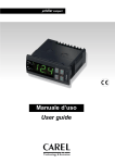
TEMPERATURE DISPLAY
SET POINT BUTTON
INSIDE YOUR CHILLER
Electrical System:
•
•
This chiller requires a power input of 220-volt single phase. The power supplier
to the controller is 24 VAC through a step-down transformer. The chiller can
operate at both 60Hz and 50Hz, however, there is a 12% reduction if cooling
capacity, and a 17% reduction in flow capacity at 50 Hz
High voltage electrical components stored in the control box. Take careful
precaution when open the door. Door must be secure in place when the unit is
operating.
CONTROLLER SETTING:
Parameters overview:
9
The Carel uchiller has many parameters available. Only a few will ever need to
be adjusted.
Parameter
R1
R2
R6
Function
Cooling Set point
Cooling Differential
Return Temperature Reading
Changing Set points:
Cooling Set point:
1. Press the “SEL” key for 5 seconds. “R1” will appear on the screen.
2. Press the “SEL” key and adjust the desire cooling value. Press the “SEL” key
to store the value.
3. Hit the “PRG” key to return to normal operation.
Refrigeration System
•
•
•
The refrigeration system is factory charged with R-134A. If the refrigeration
system has to be serviced and recharged with refrigerant, do not use any other
than R-134A.
The MICRO MAX series chiller is equipped with a refrigerant low-pressure and
high-pressure refrigerant switches. The low-pressure switch is an automatic reset
switch that will protect the compressor in the event of a refrigerant leak. It is set at
25-psi. The high-pressure switch is a manually resetting switch. The controller
turns off the refrigeration unit when it detects a high-pressure condition in the
refrigeration system. Chiller shut off at he refrigerant high pressure due to a dirty
condenser, excessive ambient temperature, or a blockage in the refrigerant line.
The high-pressure switch is set at 425-psi. Pressing the red button on the switch
will reset the circuit.
This is a medium temperature chiller. The temperature range is 45 to 90°F. The
chiller will not operate to its full capacity outside of this temperature range.
Chilled Water System
•
•
A 265 GPH (Gallons per Hour) positive displacement pump is equipped with this
chiller. Because of its design, the flow rate is not adjustable. The pressure can be
adjusted by throttling the discharge. If the discharge is throttled too much, the
internal pressure relief valve will open and bypass water back through the tank.
The pressure relief valve is factory set at 60-psi.
The water used to fill the chiller must be absolutely free of any particulate matter.
If any particles or sediment is run through the pump it will score the inside,
10
•
•
•
•
resulting in a marked decrease in pump performance. This failure is not covered
by warranty. A filter is available as an option to install to the chiller. However
the water initially placed in the reservoir must be clean.
The reservoir level must be maintained to the level marked on the sight glass.
Damage to the evaporator can result due to low water level.
Plumbing must be rubber hose, PVC, or copper. Use of any other material will
increase the chance of contamination in the chilled water system.
The chilled water reservoir is not pressurized. Do not plumb two chillers in series.
The MICRO MAX chiller is installed with a strainer on the return line to keep
foreign particles out of the system.
11
SPECIAL FEATURES
12
SERVICE BULLETIN
HERMETIC COMPRESSOR ELECTRICAL TERMINAL VENTING CAN BE
DANGEROUS
******
When the insulating material, which supports a hermetic compressor electrical terminal,
suddenly disintegrates due to physical abuse or as a result of an electrical short between
the terminal and the compressor housing, the terminal may be expelled, venting the
vaporous and liquid contents of the compressor housing and system.
If the hermetic compressor terminal PROTECTIVE COVER is not properly in place with
its weatherproofing gasket (if required) and bale strap fastening device secured, there is a
remote possibility if a terminal vents, that the vaporous and liquid discharge can be
ignited, spouting flames several feet, causing potentially severe or fatal injury to anyone
in its path.
The discharge from a venting terminal can be ignited external to the compressor if the
terminal PROTECTIVE COVER is not properly in place and if the discharge impinges
on a sufficient heat source such as, but not limited to, an open flame, electric heater, or an
electrical spark.
Ignition of the discharge can also occur at the venting terminal or inside the motorcompressor enclosure, if there is sufficient contaminant air present in the system and an
electrical arc occurs as the terminal vents.
Ignition cannot occur at the venting terminal without the presence of contaminant air, and
cannot occur externally from the venting terminal without the presence of an external
ignition source.
It is, therefore, essential that any air in a refrigeration, air conditioning, or heat pump
system be completely removed when the system is manufactured - when the system is
installed - and whenever the system is field processed as a result of field service. Field
service includes, but is not limited to, leak repairs or compressor replacement.
Eliminating air within the system prevents ignition at, or in, the hermetic compressor if a
terminal should vent, thereby reducing the hazard potential.
To reduce the possibility of external ignition, all open flame, electrical power, and other
heat sources should be extinguished or turned off prior to servicing a system.
Before using a soldering or welding torch to remove or repair tubing, make sure all the
system refrigerant charge has safely been released.
A venting terminal presents no danger to servicing personnel or anyone else in the
vicinity if the compressor terminal PROTECTIVE COVER is properly in place as shown
13
on Tecumseh Products Company drawings and diagrams using the parts as shown on
Tecumseh Products Company bills of material.
Hermetic compressors can be properly serviced without unnecessarily removing the
terminal PROTECTIVE COVER by adhering to the following service procedures:
1.
If the branch circuit, short circuit, and ground fault protective device, i.e., fuse or
circuit breaker, is open, this is a strong indication that an electrical problem exists
and must be found and corrected.
The circuit protective device rating must first be checked as required by
the National Electrical Code, and its maximum rating should coincide with
that marked on the equipment nameplate and/or on the unit wiring
diagram and/or instructions. This breaker or fuse rating should be as low
as practical. A rule of thumb is 175% times the motor-compressor RLA
(FLA on older units) as shown on the unit nameplate.
It is acceptable to first replace the fuse or reset the circuit breaker ONE TIME to
determine if it was just a nuisance opening. WARNING! The terminal
PROTECTIVE COVER must be securely in place.
2.
If the fuse or circuit breaker again opens, DO NOT continue to replace or reset, as
the equipment obviously has an electrical problem. CAUTION! Continual
resetting may cause the terminal to vent.
3.
DISCONNECT all power to the unit, making sure all power legs are open.
4.
Without removing the terminal PROTECTIVE COVER, disconnect the three
leads going to the compressor terminals at the nearest point to the compressor, and
identify them as Common (C), Start (S), and Run (R). Identification can generally
be made through the unit wiring diagram. DO NOT disconnect at the compressor
terminals at this time.
5.
With a Megger, Hi-Potential Ground Tester, or other suitable instruments which
puts out a voltage between 300 and 1500 volts, check for a ground separately
between each of the three C, S, & R leads and ground (such as an unpainted tube
on the compressor). Do not use a low voltage output instrument such as a voltohmmeter or other such continuity instruments, as these will not detect a low level
fault (ground).
6.
If a ground is indicated, then carefully remove the compressor terminal
PROTECTIVE COVER and inspect for loose leads or insulation breaks in the
lead wires.
7.
If #6 indicates no visible problem, carefully remove the leads at the compressor
terminals. CAUTION: Damage can occur to the glass embedded terminals at this
14
point if the leads are not properly removed, which can result in the terminal
venting and hot oil discharging. No ignition, however, can occur if all power is
disconnected and no external ignition source is present.
8.
Repeat #5 testing, carefully checking for ground, directly between each
compressor terminal (C, S, & R) and ground.
9.
If once again a ground is indicated, proceed to properly replace the compressor, as
it has failed and cannot be repaired.
10.
It is important to note that a volt-ohmmeter may be used only to check the
resistance and/or continuity of the motor windings. This may be done as follows:
(a)
For internal overload protected motor-compressor, the overload is located
between the common terminal of the compressor and the common motor
lead inside the compressor.
If the resistance reading between Common and Start or Common and Run
is open (infinity) and the resistance reading between Start and Run
indicates winding Resistance Values in the Tecumseh Hermetic
Compressor Service Data Book, then the internal protector is open and
time must be allowed for it to reset.
Any Common and Start, Common and Run, and Start and Run resistance
reading must be within the values shown in Tecumseh Hermetic
Compressor Service Data Book.
Three phase internal overloads open all three phases. Therefore, allow
time for reset.
(b)
For external overload protected motor-compressors, the continuity of the
overload may be checked. The resistance of all winding may also be
checked, i.e., C-S, C-R, and S-R.
(c)
Any lack of continuity (other than test indicating an open internal
protector) or improper resistance, indicates a faulty or damaged motor and
the compressor must be properly replaced, as it has failed and cannot be
repaired.
If the above indicates no problem with the compressor, then carefully reconnect the leads
to the proper compressor terminals (C, S, & R), correctly replace the terminal
PROTECTIVE COVER, gasket (if required), and the bale strap.
Then proceed to conduct similar ground and continuity test from the three lead
connection points which you previously disconnected, forward toward the incoming
power connections, to find the electrical problem. DO NOT reset the ground fault
15
protective device until you have located and corrected the problem. Refer to the Unit
Wiring Diagram and Service Manual for the proper procedure and wiring checkout.
The text of step-by-step procedures uses language and symbols, which refer to the
electrical supply as single phase. Three-phase equipment should be given equally
cautious consideration when service is necessary.
Again, we want to stress that it is essential that WHENEVER ELECTRIC POWER is
applied to the motor-compressor, the terminal PROTECTIVE COVER must be properly
in place.
Servicing refrigeration and air conditioning systems can be dangerous, and extreme
caution in all respects should be exercised by the personnel servicing such equipment.
The precautions discussed in this bulletin deal only with those dangers associated with
VENTING TERMINALS.
16
MAINTENANCE INFORMATION
1.
There are no lubrication points on the chiller. All motors have permanent lubrication
in the bearings.
2.
The water that is used in the chilled water circuit has no special requirements,
except that deionized water cannot be used. The water should be clean and some
type of water conditioner can be used. Nothing should be used in the chilled water
circuit that could damage the all copper Heat Exchanger. THIS INCLUDES THE
USE OF DEIONIZED WATER.
3.
The air-cooled condenser should be cleaned on a regular basis; depending on the
environment the chiller is installed in., check often.
4.
The water level should be maintained as close to the level as marked on the water
sight glass. You can damage the refrigeration system by the water being at a low
level, and will affect the efficiency of the unit.
5.
Caution: The compressor receivers and water pump could be hot enough to injure
one touching these components.
6.
The dial thermometer is reading the temperature of the discharge-chilled water.
7.
Please note: This is a hermetically sealed compressor. There are no necessary
maintenance requirements. Please read the service bulletins before making any
repairs.
17
TROUBLE SHOOTING - PART I
SYMPTOM
DIAGNOSIS
REMEDY
Check
Power supply
Electrical circuit
Correct circuit breaker
Repair or replace bad circuit
Line load voltage
Temperature control
Compressor overload
Low pressure switch
High pressure switch
Manual switch
Compressor
All control circuit
Correct voltage condition
Repair or replace
Replace
Repair or replace
Repair or replace
Replace
Replace
Repair
Check
Compressor won't run
Compressor runs
No refrigeration
Refrigerant leak
Stuck expansion valve
Repair leak and recharge
Replace expansion valve
High pressure trips
Condenser motor
Air over condenser restricted
Service panel not in place
Repair or replace motor
Clean condenser
Install service panel
Low pressure switch
Cutting out
Defective expansion valve
Refrigerant leak
Replace expansion valve
Repair leak
Temperature too high
Dial thermometer
Temperature controller
Water pump off
Re-adjust or replace
Replace
Check controls circuit
Temperature too cold
Temperature controller
Dial thermometer
Water pump
Repair or replace
Out of adjustment
Not circulating water
18
TROUBLE SHOOTING - PART II
REFRIGERATION SYSTEM INTERNAL PRESSURE USING REFRIGERANT R134A
* High Pressure Switch : Manual Reset - Cut out at 425 P.S.I.
* Low Pressure Switch : Automatic Reset - Cut out at 15 P.S.I.
WORKING REFRIGERANT PRESSURES R-134A
* High Pressure : 185 to 325 P.S.I.
* Low Pressure : 45 to 70 P.S.I.
***NOTE***
These pressures are under normal ambient temperatures and chilled water temperatures.
19
PARTS LIST
Micro Max Series - 230/1
If this unit has spe~ial feature(~)installed, see al!pendix for part number(s}.
Part Number
Refrigeration
RtOOC - cu
R102C - cu
R114C - cu
R146 - .5
R 146 1
R150
R152
R140 - .5
R140 - 1
R140 - 2
R160-BP
R 162-BP-C
R184
R185
Electrical
6108
E104
E109
E 109-F25
61 09-F 12
E170-1
E170
E115
6122
E400
Plumbing
P.t32
P132 - M
P132 - C
E136-30
P146
P149 - wsga
Accessories
C101
CA 1 OOMM
C100
Description
Condensing unit--MM50AQ
Condensing Unit - MM1OOAC
CondensingOnit -tyltyl1pOAC
Refrigeration Sight Glass-1/4" for MM50AC
Refrigeration.SightGlass--3/8!'{orMM4I10/150AC
Drier %" for MM50AC
Drier 3/8!!forMM1001150AC.
Expansion Valve %" x 3/8" for MM50AC
ExpansionV~.lve 3Ia!~x ~!!forMM1OOAC..
Expansion Valve 3/8" x ~" for MM150AC
Evaporator -BraledPlate"-MMpOAC
Evaporator - Brazed plate - MM100/150AC
High .Pressure$witghMM5QAC. only
Low Pressure Switch - MM50AC only
2~0/
Qty.
1
1
../.
../
1
1
1
1
1
1
1
1
1
1
1
1
1
1
3
3
1
Contactors< ~G)...Ampt440""~Qil.
4 Point Terminal Block
Fuse Block>--30>Amp
25 Amp Fuse
12 Amp Fuse
Relay Base
Ground
~witch
Love Control
../
1
../
1
Pump Motor
Clamp
Water Pressure Gauge
Water Relief>\t'alve . .
Water Level
../
1
1
1
1
1
Casters
Cabinet
Crate
../
../
..
Note:
Some water connection parts are not listed
../
../
4
1
1
Schreiber Lim ited Warranty
Schreiber warrants the product described herein
against defective m aterial or workm anship for one
year from the date of purchase.
If any part is found to be defective within the warranty period, Schreiber, or its authorized service
agent, will replace, or at Schreiber's options, repair the part free of charge for m aterials and labor.
This warranty does not cov er dam age caused by
m isuse, accident, abuse, incorrect installation or
operation. In addition, it does not cover dam age
occurring during transit, or dam age caused by or
resulting from repair or m odifications carried out
by anyone other than Schreiber or its Authorized
Service Agent.
(562) 926-3855
21