1
C.
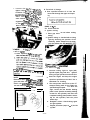
L o o s e n t h e IOU W. ,, ~“, ~~, To
tighten chain tur* ‘,W
_
2, 61 @lusters
clockwise. To Irfn *,W
,fl’ Mjustars
counterclockmw a/,
)* U,W! f o r ward. Turn ta7 vqnn
?/=?I / the
same amount ti FW+.
rv ‘l++f,t axle
alignment. (There VS. W5J”S ,,, 3ivh side
H. Front fork oil change
8. Pour specified amount of oil into the
inner tube through the upper end opening.
of rear arm and cf TV/ #,*, 9,,,rr. uoe
them to check for p--H -4;
(PAGE 14 - 15)
2-5. E L E C T R I C A L
C. Ignition timing
1. Point gap must be set before setting
timing.
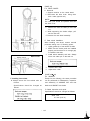
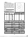
2. Ignition timing is checked with a timing
light by observing the position of the
stationary marks stamped on the stator
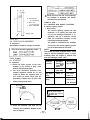
6. bewp+ - - 2. Adjuster
3. Marks for alipnant
d. After adjusting, 8~ ,..,+ .,
c ‘j’t#ten the
3. Advanced mark
1. Too dead center
2.15” BTDC at 1,200 rlmn
CAUTION:-. .*,_
3.
NOTE:
-I_
Excessive chain tense ~1) ,,W,M the en_
gine and other vita, m
’ ‘W tlu: ternion
within the specifti iir& h, ,~~ the
rear axle cotter pin * * + k
-‘--
4.
5.
“_
6.
7.
-114-
.
Connect timing light to right (left)
cylinder spark plug lead wire. Ignition
timing of right cylinder must be set first.
Start the engine and keep the engine
speed as specified on the label. Use a
tachometer for checking.
The rotor pointer should line up the “F”
stamped timing mark on the stator at a
specified engine speed. If it does not
align, loosen the two breaker backing
plate screws (breaker assembly holding
screws for left cylinder) and move the
complete backing plate (breaker assembly for left cylinder) until the point
marks align.
Retighten screws. Check timing again
for right cylinder.
Repeat procedure (steps 2 - 6) for left
cylinder.