1
Umted States Patent [19]
[111
4,120,629
Christian et al.
[45]
Oct. 17, 1978
[54]
PRODUCTION CONTROL APPARATUS
_
[75]
_
_
lnventom John Hunt Chns?an, Tucson, Arm;
James Leroy Overacker, Morgan
Hill, Calif.
[73] Assignee:
International Business Machines
Corporation, Armonk, NY.
[21]
702,638
Appl. No.:
_
[22] Flledi
[51]
3,716,128
2/1973
Edge et a1. ....................... .. 214/11 c
3,753,237
8/1973
Koontz et al.
3,909,171
3,945,790
9/1975
3/1976
Weber et al.
. 425/385 x
Puech ................................. .. 425/385
214/11 c x
Primary Examiner-Robert L. Spicer, Jr.
Attorney, Agent, or Firm—-Herbert F. Somermeyer
[57]
ABSTRACT‘
_ _
_
_
.
.
.
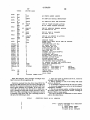
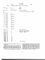
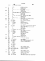
Ut1l1zat1on of product1on equlpment wlth diverse
Jul- 6’ 1976
throughput rates is optimized by a central random ac
Int. (:1.2 ....................... .. 1329c 3/00; B65G 47/48
9685 article storage apparatus disposed centrally of pc
[52] us. 01. .................................. .. 425/135; 425/317;
ripherally positioned production equipment Computer
425/385; 425/403.1; 101/27; 214/ 16.4 C;
214/11 C
controls enable fully automatic sequencing of produc
tion ?ow. The storage apparatus provide transient stor
Field of Search ................... .. 214/16.4 A, 16.4 C,
age and article queuing during intermediate successive
[58]
214/11 C; 425/137, 403.1, 385, 317; 101/27
[56]
production steps. The computer control enables auto
References Cited
matic article tracking for quality control as well as
diagnosis of automatic production equipment problems.
U.S. PATENT DOCUMENTS
3,659,974
5/1972
Neugroschl ............. ., .... .. 425/317 X
3 Claims, 3- Drawing Figures
"
20
.ARTICCES
L
TO BE
30
2 T
REJECT PORT .
HOT
14A
WRITER
'4
STAMP
IIEs DEGAUSSER
[h
<15 FINISHED
J ARTICLES
RANDOM ACCESS ARTICLE STORAGE >
F3’Rogz?ggw
82
12
-
IoI
TU
AND RETRIEVAL APPARATUS
SHIPPING
3833280; 3584284;3854605; 3054004
-
TU
TU
TU
TU
TU
TU
TU
DATA INPUT
ON ARTICLE
TO BE PROCESSED
CONTROL
PROCESSOR
3!
SBCA
2|
SERIAL
_
NUMBER
(I6
,7
CRT DISPLAY
SUPERVISORY
CONSOLE
PROCESSOR' '
AND
KB /
KEYBOARD
(‘OPERATOR
STATION
US. Patent
Oct. 17, 1978
Sheet 1 of2‘
FIGJ
S"
20
LARTICLES
<
BE
PRgsczEggfl)
HOT
30
I”22 F“ ~- R REJECT PORT)
QM
wRITER
STAMP MES DEGAUSSER
RANDOM ACCESS ARTICLE STORACE
AND RETRIEVAL APPARATUS
10f
W14
15
[I
<?
—- SHIPPING
3833280; 3584284;3854605; 3854604
TU
OATA IMPuT
0N ARTICLE
TO BE PROCESSEO
4,120,629
TU
Tu
TU
_
3|
TU
TU
Tu
TU
COMTROL
PROCESSOR
/SBCA~/ ('6
_/ /
21
SERIAL
//
NUMBER
I
17
CRT OISPLAY
SIIPERvISORY
CONSOLE
PROCESSOR
AND
KB/
ARTICLE
ID
21A
I
ARTICLE TO
CONVEYOR f 20/‘
RANDOM
H62
SM ASSIGNED
A ,4
22
STORAGE J
—
I R5)
HOT STAMP
HA
OPERATIOM
)_——%____>
(R5) \—'—//T
vwRITER
DEGAUSS
/ 1“
OPERATIOM
IRSI\JIM_+T
TEST
I
/ 23
OPERATIOM
(RS)
ISA-f
%—__q"“ "
ARTICLE TO
F'N'SHED
CONVEYOR
REJECT
ANALYSIS
‘ S
PACKAGE
FOR
SHIPMENT
24
f
I 25
KEYBOARD
U.S. Patent
I
ENTRY
Oct. 17, 1978
)
Sheet 2 of 2
4,120,629
1 DISALLOW OIIIT
SERVICE
—-~»-
PACKAGING IF
AGTIvE
.
#-
MASK ALL BUT
SERVICE
NEEDED
CARTRIDGE
INTERRUPTS
'
TESTERS IF
SERVICE REJECT
AGTIvE
PORT IF AcTIvE
POST MESSAGE IF
MICRO CHECK
S
SERVICE A4
INPUT IE ACTIVE
CHECK QUEUE
|_|M|T5
BRANCH T0
KEYBOARD H:
SERVICE HOT
SERVICE MANUAL
REQUESTED
STAMP IF ACTIVE
ENTRY/EX”
SERVICE cm‘ H:
SERVICE SERVO
WRITER
ACTIVEIF
SERVICE TIME
OIIT MONITOR
MESSAGES
PEMOIMG
SERvIGE TEST
ROUTINE
GO TO GENERAL
RvI
SE
CE
SERVICE X Y IF
ACTIVE
I
UTS—TO—UTS
SERVICE
CHANNEL
AcTIvE
"SERvIGE SBGA
(HOST) IF
SERvIGE OuAEITY
TESTER IF
' ACTIVE
ACTIVE
SERVICE LINE
PRIMTER
SERvIGE TRAcE
REAOER IF
'
'
CHECK 370
CHANNEL FOR
POLL REQUEST
SERvIcE A4
OUTPUT IF
ACTIVE
SERVICE 3830
CHANNEL IF
SERvIGE TIMER
ACTIVE
SERVICE wIMOER
IF AcTIvE
HG 3
1
4, 120,629
2
retest is called for ensuring that the appropriate yield of
the magnetic material is achieved. Such retesting results
in variable test times for tape containing cartridges
PRODUCTION CONTROL APPARATUS
U.S. PATENTS INCORPORATED’ BY
being automatically produced. Accordingly, seriatim
REFERENCE
testing is not a viable production solution.
In an attempt to solve variable production and test
U.S. Pat. No. 3,825,208 shows an article to be advan
tageously processed by apparatus and methods of the
present invention.
rates, production lines have placed slow operating ma
chines in parallel such that a single-?ow production line
U.S. Pat. No. 3,833,280 shows a random access article
may have a plurality of parallel paths through the slow
machines, and a single serial path through a high pro
duction machine. Such solutions appear to be expensive
and exhibit a limited degree of ?exibility. A better solu
storage and retrieval apparatus employable as the arti
cle random access storage apparatus for practicing the
present invention.
tion for high-speed production of articles, particularly
U.S. Pat. No. 3,584,284 shows an article transport
control apparatus usable with the U.S. Pat. No.
3,833,280 illustrated apparatus.
magnetic tape and related articles, is desired.
15
U.S. Pat. No. 3,854,605 shows an article autoloader
and associated recorder usable in connection with the
U.S. Pat. No. 3,833,280 illustrated apparatus.
SUMMARY OF THE INVENTION
It is an object of the invention to provide a highly
?exible, fully computerized production apparatus hav
U.S. Pat. No. 3,854,604 shows an article transporter
ing a maximal degree of production rate ?exibility,
usable with the U.S. Pat. No. 3,833,280 illustrated appa 20 while enhancing monitoring capabilities.
An apparatus incorporating the present invention is
ratus.
characterized by a random access article storage and
BACKGROUND OF THE INVENTION
retrieval unit with various diverse production units
The present invention relates to production apparatus
including test units, disposed about the periphery of
particularly, to computerized control of such apparatus. 25 such random access storage unit. A programmed com
The production and quality control of large numbers
puter controls the transfer of articles within the storage
of product or articles incurs substantial cost in labor and
apparatus and between the diverse manufacturing appa
capital equipment. For controlling such cost, it is imper
ratus in a manner that quality control is facilitated while
ative that a certain amount of automation be employed.
maintaining each of the diverse manufacturing and test
Depending upon the manufacturing process, as well as 30 apparatus, utilization to a maximal extent. Queues for
the product being produced, such automation can be
the various diverse manufacturing and test apparatus
consists of article sto'rage cell locations within the stor
age apparatus, each article having but one storage cell
achieved with various degrees of success. As an exam
ple, the assemblage of two diverse parts having close
tolerance requirements can result in very expensive
location for facilitating article tracing.
production costs. A prior solution to such a problem 35 In another aspect of the invention, the computerized
was to measure each of the parts and separately store
control of such apparatus, includes a simple program
same in two different random access article storage
driver loop for selectively invoking one of a plurality of
units. Storage would be in accordance with the mea
control computer programs which not only control and
surements made such that all parts having like toler
monitor operation of the central random access article
ances are stored together. Then, under computer con
storage and retrieval unit, but also the diverse manufac
trol, parts having matching tolerances would be sup
turing and test apparatus, as well as generating a trace
plied from the random access storage unit to an auto
record for each article being processed through the
manufacturing apparatus. Quality control of the diverse
apparatus is also provided by computer program con
matic assembler, wherein the parts would be mated
based upon their tolerance measurements.
In other automatic production equipment such as in 45 trol.
semi-conductor manufacturer, classi?cation of compo
The foregoing and other objects, features and advan
nents produced in accordance with predetermined elec
tages of the invention will be apparent from the follow
trical test criteria, was a major portion of a production
process. The produced electrical components were
categorized in accordance with a plurality of tests and
ing more particular description of preferred embodi
ments of the invention, as illustrated in the accompany
ing drawings.
sorted, all under computer control. The testing opera
tions were such that all of the components could be
tested in seriatim, i.e., the test procedures for one com- .
facility employing the present invention.
ponent required the same amount of time as for any
other component. Accordingly, with such simpli?ed
test procedures, a seriatim approach to the automation
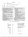
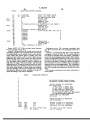
THE DRAWINGS
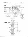
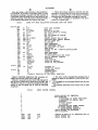
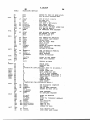
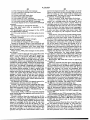
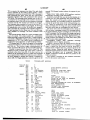
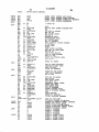
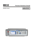
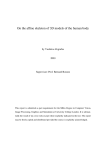
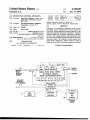
FIG. 1 is a block diagram of an article production
55
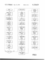
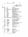
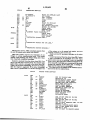
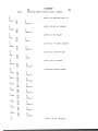
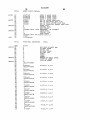
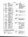
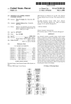
FIG. 2 is a ?ow diagram illustrating operation of the
of testing for the satisfactory solution. However, not all
FIG. 1 illustrated apparatus.
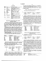
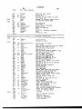
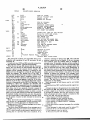
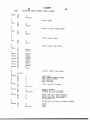
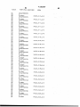
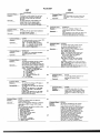
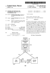
FIG. 3 is a ?ow diagram of the computer control
components are subject to such easy and predictable
test times. As an example, magnetic tape cartridges
program driver aspects for automatically operating the
have a plurality of characteristics, all of which can be
tested. The degrees of magnetic recording and high
quality control considerations require that various pa
FIG. 1 illustrated apparatus.
DETAILED DESCRIPTION
Referring now more particularly to the attended
drawings, like numerals indicate like parts and struc
tural features in the various views and diagrams. FIG. 1
rameters be tested. Such parameters may interact such
that retesting or more extensive testing may be called
for. For example, if a particular area of a magnetic 65 illustrates a typical apparatus incorporating the present
medium was scanned by a test transducer, lack of a
invention. It includesa centrally controlled and located
successful test may be due to debris disposed intermedi
random access article storage and retrieval apparatus 10
ate the test transducer and the medium. Accordingly, a
surrounded by a plurality of manufacturing and test
3
4,120,629
4
apparatus. The present apparatus is designed to produce
unit 11, is as shown in the referenced patents, for appa
an article as shown in U.S. Pat. No. 3,825,208, which
ratus 10.
shows the physical construction of the article and as
shown in U.S. Pat. No. 3,932,894, which shows the
format on the magnetic medium in the article of U.S.
Servo writer 12 consists of a multiple head magnetic
tape recorder for recording signals along the length of
Pat. No. 3,825,208, which is advantageously produced
the medium. The article is received with the signals
and tested by the FIG. 1 illustrated apparatus. A ?rst of
recorded thereon using known magnetic recording
the peripheral manufacturing apparatus is a hot stamp
unit 11 which receives under program control, articles
to be produced. After hot stamping which will be later
gaussed prior to the recording. This is achieved by
passing the article physically through a magnetic ?eld
Subsequently, servo writer 12 receives the article.
techniques. It is preferred that the tape may be de
such as that provided by a permanent magnet or AC
described, the article may be placed in a queue within
apparatus 10 for transfer to servo writer degausser 12.
Servo writer degausser 12 adds a format to the magnetic
media in the article of U.S. Pat. No. 3,825,208, as shown
magnetic ?eld. Subsequent to the writer 12 operation as
at- 12A, the cartridge is returned to apparatus 10 for
enqueuing to a test unit (TU). Upon entry into a test unit
(TU) the test operation at 23 is performed. Such test
in U.S. Pat. No. 3,932,894. Subsequently thereto, the
verifying that the appropriate format has been recorded
operation veri?es the continuity of the magnetic coding
of the magnetic medium of the data cartridge. Also, the
ability of the magnetic medium to be unspooled and
on the magnetic medium. If the test is unsuccessful, the
spooled is verti?ed. In the event a certain percentage of
article is transferred from the writer degausser 12 to
apparatus 10, or to one of the many test units (TU) for
article is supplied to reject port 14 for further analysis 20 the coating is unsatisfactory for magnetic recording
purposes, particularly of the data processing type, the
beyond the scope of the present invention. If the test
article is rejected and sent to reject port 14. Control
was successful, the article is returned to apparatus 10
processor 16 tallies the number of articles being rejected
awaiting transfer via conveyor 15 as a ?nished article to
for input to quality control (QC). Following the test
be shipped. All of the above described apparatus is
operation 23, the article is returned to storage, awaiting
sequenced, operated and monitored by control proces
transfer to a packing machine (not shown) via conveyor
sor 16 which'contains microcode as will be described,
15. Upon accumulation of a predetermined number of
for effectuating the manufacture of the articles. Control
articles within apparatus 10, all of the articles to be
processor 16 is'connected to a supervisory processor,
packaged are transferred over conveyor 15 at step 15A,
such as an IBM 370 Model 155 or 168, (manufactured
and sold by International Business Machines Corpora
30
and packaged for shipment at 24. The packaging appa
ratus is not shown.
tion, Armonk, N.Y.), which serves as a factory control
computer. The supervisory processor 17 is connected to
To assist in quality control, manual entry station 14A
receives articles to enable analyzing random samples of
articles received by apparatus 10 at various stages of the
products.
The description assumes that the magnetic medium in 35 above described manufacturing operation. As shown in
FIG. 2, raw received articles can be analyzed, as well as
the form of an elongated tape and the various portions
articles at any stage of the operation.
of the article, have been assembled by apparatus (not
Control processor 16 is responsive to an input sensing
shown) and supplied to a suitable conveyor line 20 for
switch 30 for verifying that an article has been received,
transfer to apparatus 10. Upon the completion of the
initial assembly of the physical parts, the article is deliv 40 in accordance with the serial number assigned at 21, for
transfer to the assigned storage location within appara
ered to conveyor 20 and a serial number is assigned to
tus 10. The addressing and identi?cation of such ‘storage
each of the articles. This is achieved in the illustrated
other apparatus (not shown) for manufacturing diverse
locations can be as shown in the referenced patents and
as indicated later in the microcode listings.
apparatus via a punched card or unit record reader
represented by symbol 21. The serial number is inter
nally recorded by the control processor which, at that
time, assigns a storage location within apparatus 10, to
the article to be processed. In FIG. 2, the ?ow-chart
showing the flow of articles through the FIG. 1 illus
trated apparatus, shows the assignment of serial number
at 21A, whereupon the article is placed on conveyor 20
at 20A, and the serial number recorded by the control
processor 16. The control processor 16 then determines
whether or not hot stamp unit 11 is available. If it is not
available, the article is received by apparatus 10 and
45
Further, reject port 14 is adapted to receive articles
after reject analysis as at 25. In such a situation, control
processor 16 maintains a serial number from 21, and
assigned storage location, until a console (not shown)
entry orders control processor 16 to erase the serial
number from the manufacturing operation. In this man
ner, integrity of the entire manufacturing operation is
maintained through'diverse forms of tests and functions.
It is to be understood that additional diverse testing and
control may be achieved by adding additional units to
the FIG. 1 illustrated apparatus. Further, in a practical
embodiment, control processor 16 monitors operations
of the parts assembly apparatus (not shown) as indicated
by lines 31. Such apparatus takes all of the parts of the
transferred to the assigned storage location, as repre
sented by the spaced lines at 22. Such stored articles are
a queue of work to be performed by hot stamp unit 11.
If the queue is empty, the article is immediately trans
cartridge and assembles them together. Additionally,
ferred to the hot stamp unit 11. Normally, the queue is
not empty, requiring the article to reside in apparatus 10 60 magnetic medium is slit to the appropriate width and
automatically wound on a spool of the cartridge by a
for a short time.
The cartridge is hot stamped to visually record the
assigned serial number at the free end of the tape as
shown in U.S. Pat. No. 3,932,894. Hot stamping is
achieved by a heated die pressed against the polyester
based magnetic medium. Such an operation is well
known and not described for that reason. Transfer of
the article from the storage apparatus to the hot stamp
winder (not shown) before being transferred to input
conveyor 20.
Before going into the details of the program control,
65 control processor 16 is described. The architecture of
the processor is as shown in FIG. 3 of U.S. Pat. No.
3,654,617 but using the instruction words and as de
?ned and mnemonics as listed hereinafter, rather than
4, 120,629 '
5
6
the limited instruction repertoire used in the referenced
US. Pat. No. 3,654,617. The A and B bus of US. Pat.
No. 3,654,617 is the X and Y bus of the control proces
sor 16. As described herein, the machine instruction
level description, is based upon an assembler language
When indirect addressing is speci?ed for a register
?eld, it means that the address of the register to be
operated on is contained in the register Rl.
for assemblying the actual numeric instructions (binary
contained in the register speci?ed in the Al ?eld.
l’s and O’s) such that any machine architecture can be
In this document, operand ?elds will be numbered
left to right, from 1 to 3. An alphabetic character is also
When a Control Store or Main Store operand ?eld is
addressed indirectly, the CS or MS effective address is
employed using the later described microcode elements.
used to indicate what type of operand is being speci?ed.
INSTRUCTION WORDS AND MNEMONICS FOR 10 The following characters are used:
CONTROL PROCESSOR 16
R ; Register Field (in LSR)
Each instruction word in source language form in
I = Immediate Data Field (contained in instruction
cludes:
word)
Label: Identify machine instructions, etc. (data ac
A = A control Store or Main Store Address Field
cess). The label is useful when an assembler converts
X = An Index Register used as an Address Field or
‘the source statements into machine coding. The label
as a Sub?eld
?eld includes only symbols, de?ned below:
S = A Shift Control Field
N = A decimal or hexadecimal self-de?ning term
Storage areas, instructions, and other elements may
be given symbolic names for the purpose of referring to
them in a program. All symbols must conform to the 20
following rules:
1. The symbol must not consist of more than six char
acters. The ?rst character must be alphameric. The
other characters may be combinations of alpharneric
and numeric digits.
LANGUAGE
The source language to assembler constraints are set
forth herein for achieving one machine instruction for
each symbolic language instruction. -
RELATIVE ADDRESSING
25
2. No special characters may be included in a symbol.
3. No blanks are allowed in a symbol.
4. A symbol may be de?ned only once in an assembly.
Relative addressing is ‘the technique of addressing
instructions or data areas by designating their respective
locations in relation to the Control Store Address Reg
ister CSAR or to some symbolic location (label). Rela
ment is assigned the value designated in the operand 30 tive addressing can be effected using the current'value
?eld. If the label ?eld is left blank, it is ignored by the
of the CSAR by specifying an asterisk as the first char
assembler. If column 1 contains an asterisk ("), the en
acter of the operand ?elds. ‘Data areas can be referred ‘to
tire statement is treated as a comment and appears only
by their symbolic name + or — some value.
5. A symbol used as a name entry in an equate state
in a program listing and is not used as a machine instruc
35
tion.
CHARACTER SET
Source language instructions and comments are writ
OPERATION
ten using the following characters:
'
'
Each machine instruction has a unique mnemonic
Alphameric: A through Z and S, #, @
operation'code associated with it. The mnemonics are
Numeric: 0 through 9
40
indicated below with the various instructions.
Special Characters: + — , " ( ) ' blank
Each machine ALU function has been assigned a
In addition, any of the 256 punch combinations may
unique mnemonic. An ALU function may be speci?ed
be used anywhere that characters may appear between
with all instruction mnemonics except BRANCH and
BRANCH AND LINK. If an operation mnemonic is
coded and no ALU functin mnemonic is coded, the
assembler defaults to the PASS X (PX) ALU function.
All extended mnemonics have an implied ALU function
associated with them, as later described.
'
OPERAND
paired apostrophes and in comments.
INSTRUCTIONS
Instructions in the source language activate the pro
grammable machine to execute one machine instruc
tion. There are three program controlling type instruc
tions:
50
The operand ?eld is used to specify sub?elds in in
structions and constants. Operand ?elds are discussed in
Section 6.2.
The comment ?eld appears to the right of the oper
and ?eld and must be separated from it by at least one 55
blank.
OPERAND FIELDS AND SUBFIELDS
Some symbolic operands are written as a single ?eld,
others as a single ?eld with sub?elds, and still others as
multiple ?elds. Fields and sub?elds in a symbolic oper
and may be represented either by symbolic names or by
decimal or hexadecimal self-de?ning terms. Operand
Mnemonic
Instruction
ORG
MORG
De?ne origin in control store
De?ne origin in main store
END
End of source program
The ALU functions to be named in an instruction
word are as follows:
Mne
monic
Name
X]
XD
X incremented The contents of the X register plus 1
X Decremented The contents of the X register minus 1
Resulting ALU Output
?elds are separated by a comma. Up to three ?elds may
ADD
Add
be coded for some UTS machine operations. Operand 65
sub?elds must be enclosed in parentheses. Operand
?elds enclosed in parentheses indicate that indirect ad
dressing is to be used.
SUB
Subtract
The algebraic sum of the X and Y
registers
_ The Y register subtracted from the
X register
ADC
Add with carry
The algabraic sum of the X and Y
registers plus the contents of the
carry latch
4,120,629
7
-cont1nued
Mne
monic
Name
Subtract with
SBD
Subtract and
decrement
Resulting ALU Output
The Y register subtracted from the
X register minus the contents of
the borrow latch
The Y register subtracted from the X
register minus I
TC
Two's comple-
The two's completement ofOOOl
ment
(FFFFY
PX
PY
PZ
AND
Pass X
Pass Y
Pass Zero
AND
The contents of the X register
The contents of the Y register
Zero
The logical “And“ of the X and Y
SBB
borrow
registers
The logical
registers
OR
OR
EOR
Exclusive Or
‘
‘
,
B
the control store address contained in X1. Examples 3,
4, and 5 are all “displacement” branches. The EA is
generated by adding the displacement of +N, —N, or
Al to the current setting of the Control Store Address
Register CSAR.
TEST AND BRANCH INSTRUCTIONS
The format of these instructions is:
.
LABEL
A symbol
"Or“ of the X and Y
OPERATION
ALU-
OPERAND
See below
Any ALU
Rt, 12, A3
or blank
function
The logical "Exclusive Or" of the X
and Y registers
XNY
X and Not Y
The logical “And“ of the X register
and the one‘s complement of the Y
YNX
Y and Not X
The logical "And" of the Y register
and the one‘s complement of the X
TEST and BRANCH instructions place either the
high order byte or the low order byte of the speci?ed 2
register
byte (16 bit) register (R1) into the X register and the 8
bits of immediate data (I2) into the Y register. The spec
?ed ALU function is performed and the resulting condi
20 tion code is compared to the condition code of the
instruction. The signal contents of registers X and Y are
BRANCH AND BRANCH AND LINK
not changed. If the condition codes match, the branch
INSTRUCTIONS
(to A3) it taken. If there is not a match, the next sequen
tial instruction is executed. The displacement of A3
BRANCH and BRANCH AND LINK instructions
are very similar. The only difference between the two is 25 must not be greater than + 127 or — I28. The TEST and
BRANCH mnemonics are:
that when a BRANCH AND LINK is speci?ed, the
Control Store Address Register CSAR contents are
stored in the X register. The instructions operate as
High Order Byte Low Order Byte Meaning
follows:
register
If the BRANCH or BRANCH AND LINK is un 30
conditional or if the condition code implied by the in
struction mnemonic matches the condition code of the
ALU output at the start of instruction execution, a
branch is taken to the effective control store address
(EA). If the condition code of the instruction does not 35
match that of the ALU output, the next sequential in
struction is executed.
The list below shows the eight BRANCH mnemonics
and the eight BRANCH AND LINK mnemonics
Branch
Branch and Link
Mnemonic
Mncmonic
THB
TLB
THBO
THBP
THBN
TLBO
TLBP
TLBN
Branch unconditional
Branch on over?ow
Branch on plus
Branch on negative
THBZ
TLBZ
Branch on zero
THBNP
THBNN
TLBNP
TLBNN
Branch on not plus
Branch on not negative
'I'HBNZ
TLBNZ
Branch on not zero
READ AND WRITE REGISTER MASKED
INSTRUCTIONS
The format of the READ and WRITE REGISTER
MASKED instructions is:
Meaning
B
BO
BP
BN
BAL
BALO
BALP
BALN
Branch
Branch
Branch
Branch
Unconditional
on over?ow
on plus
on negative
82
BALZ
Branch on zero
BNP
BNN
BALNP
BALNN
Branch on not plus
Branch on not negative
BNZ
BALNZ
Branch on not zero
BRANCH and BRANCK AND LINH instructions
control store effective addresses (EA) are generated
depending on the operand format used.
The following examples illustrate effective address
generation for these instructions.
LABEL
45
A symbol
OPERATION
ALU
See below
Any ALU
R1. I2. or
function
(RI), I2
or blank
OPERAND
Both the READ REGISTER MASKED and the
WRITE REGISTER MASKED instructions read the
50 contents of the speci?ed register (RI) into either the X
or the Y register as indicated by the operation tnne
monic. The immediate data (12) is read into the opposite
register (X or Y). The speci?ed ALU function is per
formed and in the case of the READ REGISTER
55
MASKED instruction, this completes the operation.
The WRITE REGISTER MASKED instruction re
Example
Label
Operation
ALU
Operand
l
A symbol
Any valid
Blank
Al
2
or blank
Branch or
Al (XI)
3
Branch
(XI)
4
and
'+N
5
Link
' —N
6
Mnemonic
‘Al
writes the speci?ed register (Rl) with the output of the
ALU completing the operation. if the RI ?eld of the
operand is enclosed in parentheses, it indicates indirect
register addressing.
The following operation mnemonics have been de
?ned for the READ and WRITE REGISTER
MASKED instructions:
Example 1 above shows a “direct" branch to the
control store address represented by the value Al. Ex 65
ample 2 is an “indexed” branch. The EA is generated by
adding the control storage address Al to the contents of
index register XI. Example 3 is an "indirect" branch to
Mnemonic
Function
LDX
LDY
STX
Read (load) Rl to X. Mask to Y
Read (load) R1 to Y. Mask to X
Read and write (store) R1 to X. Mask to Y
4, 120,629
-continued
.
Mnemonic
Function
-
STY
Read and write (store)4Rl to Y, Mask to X
MOVE/MODIFY DOUBLE and the MOVE/
MODIFY DOUBLE with SWAP. Formats for these
.
instructions are:
,
5
MOVE/MODIFY REGISTER INSTRUCTIONS
The MOVE/MODIFY REGISTER instructions
have several variations. The basic form .of the MOVE/
MODIFY instructions will be explained ?rst. All other
forms of the instruction will be explained later. The
format of the basic MOVE/MODIFY instructions is
-
LABEL
OPERATION
ALU
OPERAND
A symbol
MDX or MDY
Any ALU
R1, R2, S3
LABEL
Asymbol
or blank
OPERATION
MDXD
ALU
or Any ALU
OPERAND
R1
or
MDYD
_
MDXDS
or function
or
R1, R2
or
LDXD
LDYD
LDXDS
R1
R1, R2
R1. (R2)
or
or
LDYDS
(R1), R2
MDYDS
or
The double forms of the MOVE/MODIFY instruc
tions move the contents of the “From” register (R2)
into either the X or Y register as implied by the opera
function
or blank
10
The last MOVE/MODIFY instructions are the
tion mnemonic. The contents of the “To” register are
These instructions move the contents of the “from”
moved into the opposite register (X or Y). The speci?ed
register (R2) into either X or Y register as implied by 20 ALU function is performed and in the case of the “Load
the operation mnemonic. The speci?ed ALU function is
performed and then the speci?ed shift function is done
Double” (LDXD/LDYD) instruction, this completes
the operation. If a MOVE DOUBLE SWAP or a
on the output of the ALU. The output of the ALU is
then stored in the “To” register (R1). This is the only
LOAD DOUBLE SWAP is coded, bits 0-7 and bits
8-15 of the ALU output are swapped. The MOVE
instruction that has a shift function. A shift, left or right, 25 DOUBLE and MOVE DOUBLE SWAP instructions
logical or rotate, from 1 to 4 bit positions may be done.
rewrite the resulting ALU output back into the “To”
The S3 ?eld of the operand de?nes the type of the shift
register. Either the “from" or the "To” register may be
to be done. The list below shows the valid forms of the
addressed indirectly, but not both. No shifting is permit
operand shift ?eld.
ted with the MOVE/MODIFY DOUBLE instructions.
RLL'r] = Rotate left logical
WRITE MAIN STORE INSTRUCTIONS
RRL'r; = Rotate right logical
SLL'q = Shift left logical
Write main store instructions use any one of three
SRL'r] = Shift right logical
different sources of data. They are:
Note: 1] is a decimal number from 1 to 4.
l. The previous contents of the X and Y registers.
Indirect addressing is permitted on either the “From”
2. Immediate data.
register or the “To” register but not both. If any register
3. An LSR or external register.
is addressed indirectly, no shift function is allowed.
The format of the WRITE MAIN STORE instruc
tions that use the previous contents of the X and Y
If only .the R1 ?eld of the operand is coded, the RI
registers is:
?eld becomes both the “From” and the “To” register.
The following chart shows all of the valid operand
formats for the MDX/MDY instructions.
OPERATION
WS
or blank
OPERAND
FORMAT
MEANING
R1
R1, R2
R1 = From and To reg.
R1 ‘ To reg., R2 = From Reg.
RI, S2
R1 ' From and To Reg. with shift
R1, R2, S3
(R1), R2
R1, (R2)
R1 ’ To reg., R2 = From reg. with shift
R1 = Indirect, R2 = Direct
R1 ’ Direct, R2 = Indirect
OPERATION
MDXS or MDYS
ALU
Any ALU
function
'
ALU
Any ALU
function
OPERAND
Al
or
Al (X1)
or
(X1)
WSI or WSD
(X1)
In all of the examples above the speci?ed ALU func
tion is performed and the resulting ALU output is
Another form of the MOVE/MODIFY instructions
is a MOVE/MODIFY with SWAP. The format of this
instruction is:
LABEL
A symbol
or blank
LABEL
A symbol
OPERAND
R1 or
R1, R2 or
(R1), R2 or
stored in the main store effective address EA. The main
store EA is generated depending on the format of the
operand used. If the operand coded is like the ?rst ex
ample above, the main store EA is the main store ad
dress represented by Al. In the second example, the EA
is the value of Al plus the contents of the index register
X1. If the third example is used, the main store EA is
contained in the register SI.
If the WRITE STORAGE and INCREMENT
(W S1) or the WRITE STORAGE and DECREMENT
(W SD) mnemonic is used, the third operand type (Xl)
R1, (R2)
These MOVE/MODIFY instructions operate the
same as the MDX/MDY operations. Then, after the
ALU function is performed, bits 0-7 bits 8-15 of the '
must be used and the contents of the register are incre
mented or decremented by one after the instruction is
executed.
WRITE MAIN STORE MASKED (immediate
ALU output are swapped. The examples above show all 65 data) instructions have the following format:
valid operand formats for the MDXS and MDYS in
structions. When a shift operand is speci?ed, the shift is
done ?rst, then the swap.
‘
LABEL
A symbol
OPERATION
ALU
WSM
or Any ALU
OPERAND
(Xl). l2
4,120,629
11
continued
LABEL
0 P ERATION
or blank
WSMI
ALU
or function
WSMD
12
The EXTENDED MNEMONICS fall into three
classe s. They are :
OPERAND
.
.
.
1. RR — Register
to Reglster
Operations.
’
5
RI —— Register/Immediate Operations.
3. RS — Register/Storage Operations.
_
The format for all extended mnemonics is:
These three instructions place the immediate data (I2)
into the Y register. The speci?ed ALU function is per
formed and the ALU output is stored in the main store
EA. In all cases, the main store EA is contained in the 10
LABEL OPERATION
A Symbol Extended
register x1. If the WSMI or the WSMD mnemonic 15
°' "18"“
used, the contents of the register R1 will be incremented
ALU
Blank
‘““""°“‘°
OPERAND
1- I
-
I
or decremented after the main store EA is generated.
Because of the format indicated above, only the oper
The third type of write main store instruction uses
ation and basic operand ?elds are shown. The class of
signals stored in LSR. The formats are;
15 instruction (RR, R1, or RS) will be shown as well as the
equivalent unextended instruction. All indirect address
ing rules that are applicable to the basic operand for
LABEL
OPERATION
ALU
OPERAND
A symbol
or blank
WSR, LDS
Any ALU
function
RI. Al
Rl. (XI)
'
WSRI ' LDSI or
\V RD, LDSD
S
_
R
l. Xl
(
mats are valid for the extended codes.
or
20
LOAD INSTRUCTIONS
———-—-—-—'—
)
Mnemonic
.
.
These 1nstruct1ons load the contents of the speci?ed
.
.
.
-
register (R1) into the Y register. The spec1?ed ALU
.
Operand
Class
Equ1valent
LR
Rl, R2
RR
MDX PX RI. R2
LRl
R1. 12
RI
STX PY R1- 12
L
R1. A2
RS
STS PY R1. A2
UN
Rl (x2)
RS
STS] W R], on)
function is performed and the ALU output is stored in 25
the main store EA. The LDS instruction can have a
direct main store EA (A1) or an indirect main store EA
The LOAD INSTRUCTIONS place the colnents of
(contained in X1) TheLDSI and LDSD instructions
the second operand 1n the ?rst operand location. The
can only have an indirect EA. As with the WSMI and
Second opera"? ‘5 not chzlnged' The Load and Incm'
WSMD instructions’ the LDSI and LDSD instructions 30 ment Instruction (LIN) mcrements the contents of
increment or decrement the contents of the register X1
at the end of the instruction.
“X2” after the load ‘5 parformed'
READ MAIN STORE INSTRUCTIONS
————*:4T°RE
INSTRUCT‘ONS
nemomc
Operand
Class_
READ MAIN STORE instructions read the con- 35
tents of the main store effective address into the Y regis-
ST
STIN
-
RL A1
R5
.
Equ1valent
LDS PY R1, A2
R1- 043)
R5
LDS‘ W R" (X2)
ter or through the Y register directly to a LSR. The
“Read Storage" instructions shown below have the
The sToRE INSTRUCTIONS place the contents of
same effective address generation as their correspond’ 40 the ?rst operand in the second operand main store loca
ing “write storage" instruclions-
tion. The ?rst operand is not changed. The Store and
The formal of {he READ MAIN STORE I0 ALU
instructions isi
Increment Instruction (STIN) increments the contents
of “X2" after the store is performed.
LABEL
A symbol
OPERATION
RS
ALU
Any ALU
°' blank
OPERAND
Al
or
A‘ ix‘)
45
°'
R8] or RSD
so
The format of the READ MAIN STORE TO REG
ISTER instructions is:
LABEL
OPERATION
ALU
OPERAND
A symbol
RSR. STS
Any ALU
RI. Al
or blank
RSR], STS] or
function
RSRD' STSD
or
COMPARE INSTRUCTIONS
Mncmonic
Operand
Class
Equivalent
cR
CLR
R1. R2
R1. R2
RR
RR
LDYD sun R1, R2
LDYD EOR R1. R2
CRI
CLRI
R1. 12
R1. 12
R1
R1
LDX SUB R1,12
LDY EOR R1. 12
The ?rst operand is compared with the second oper
and and the result determines the setting of the condi
“on code‘
55
Rl- (XI)
5ND INSTRUCTIONS
R!‘ (XI)
nemome
NR
NR1
LEVEL EXIT INSTRUCTION
‘
V ’
Operand
Class
Equwalent
R1. R2
R1. 12
RR
R1
MDXD AND RI. R2
sTx AND R1. 12
6O
The second operand is AND’ed with the ?rst oper
and and the result is placed in the ?rst operand location.
The LEVEL EXIT instruction is used to exit from an
interrupt level. All that is required is an operation mne
monic of LEX.
The second operand is unchanged.
65
EXTENDED MNEMONICS
Extended mnemonics make the hardward register (X,
Y, and ALU) transparent to the user.
(QB-INSTRUCTIONS
Wwmvnic
operand
A oR
R1. R2
C11“
Equivalent
RR
MDXD 0R R1. R2
4,120,629
13
-continued
14
I
OR INSTRUCTIONS
,.
\ -continued
SHIFT AND ROTATE INSTRUCTIONS
Mnemonic
Operand
Class
Equivalent
Mnemonic
ORI
RI, I2
RI
STX OR R1, I2
vRRL
Operand
Class
- . R1, I2
RI
Equivalent
' MDX PX R1, RRL'!)
The contents of the ?rst operand (R1) are shifted or
rotated left or right the number of bits speci?ed by the
12 operand. The I2 operand must be a decimal number
The second operand is OR’ed with the ?rst operand
and the result is placed in the ?rst operand location. The .
second operand is unchanged.
10 from 1 to 4.
EXCLUSIVE OR INSTRUCTIONS
Mnemonic
Operand
Class
Equivalent
XR
XRI
R1, R2
R1, I2
RR
Rl
MDXD EOR R1, R2
STX EOR R1, I2
SPECIAL INSTRUCTIONS
15
Mnemonic
Operand
SP]
11
' ' RI
Class
DIL
EIL
11
11
RI
RI
Equivalent
STX OR GLX'OOXO'
STX OR 6|,X’000X'
STX AND 6I,X'FFFX'
The second operand is exclusive OR’ed with the ?rst
operand, and the result is placed in the ?rst operand
location. The second operand is unchanged.
These three instructions are provided to allow the
programmer to manipulate interrupt levels. In all cases,
the T1 ?eld is a decimal number 0 to 3 representing
interrupt levels 0 to 3.
SP1 = Set Programmed Interrupt
ADD INSTRUCTIONS
Mnemonic
Operand
Class
Equivalent
AR
ARI
R1, R2
R1, 12
RR
RI
MDXD ADD R1, R2
srx ADD R1, 12
25
DIL = Disable Interrupt Level
EIL = Enable Interrupt’ Level
MICROCODE FOR CONTROL PROCESSOR 16
The second operand is added to the ?rst operand, and
the sum is placed in the ?rst operand location. The sign
and magnitude of the sum determine the condition code.
Source code is included only for the important oper
ating routines which perform functions not readily ap
30 parent or known from the brief description and the
The second operand is not changed.
present state of related arts. Driver Loop, DR, scans
active ?ags and gives control to later described service
SUBTRACT INSTRUCTIONS
routines as needed.
Mnemonic
Operand
Class
Equivalent
'
SR
SRI
R], R2
R1, 12
RR
RI
MDYD SUB R1, R2
STX SUB R1, I2
The driver loop is a closed set of microcode instruc
35 tions which checks various indicators and gives control
to service and functional microcode routines as de
scribed below.
Service or function steps performed are:
' The second‘operand is subtracted from the ?rst oper
and, and the di?'erence is placed in the ?rst operand
location. The sign and magnitude of the difference de
. Sets channel interrupt mask
termine the condition code. The second operand is not
. Detects operator request
. Operator display
. Detects micro checks
changed.
INCREMENT INSTRUCTIONS
45
Mnemonie
Operand
Class
Equivalent
IR
R1, R2 ‘Note
RR
MDX XI R1, R2
. Test routine ‘service
. General Service
. Printer Service
. Cartridge Tester Service
. A4 Input Port Service
10. Hot Stamp Service -
The contents of the second operand are incremented
by +1 and the result is placed in the ?rst operand loca 50
tion. The second operand is not changed.
l1. Servo Writer Service
. XY Carriage Service
. Host Service
. 370 Channel Poll Service
. TU Channel Service
DECREMENT INSTRUCTIONS
. Winder Service
Mnemonic
Operand
Class
Equivalent
DR
R1, R2 ‘Note
RR
MDX XD R1, R2.
55
The contents of the second operand are decremented
. Manual Entry Station Service
. Device Time Out Service
by +1 and the result is placed in the ?rst operand loca
tion. The second operand is not changed.
Y
. Trace Reader Service
7
‘Note: If only the R1 ?eld is coded; that register will be
incremented or decremented.
,
,
. Packaging Service
. Reject Port Service
. Queue Limit Service
. Quality On Line Tester Service
. Special Channel Service
. A4 OutputIPort Service (output from unit 10)
_
. Timer Service
SHIFT AND ROTATE INSTRUCTIONS
Mnemonic
Operand
Class
SIL
R1, 12
RI
SRL
RLL
R1, 12
Rl, I2
RI
‘RI; a‘
Equivalent ‘
MDX PX R1,‘ SLL'q
. MDX. PX R1, SRL'I)
65
Steps 8 through"2_6 are executed only if the driver
loop is running. START and STOP commands with no
operands are used to control the driver loop. For most
of the service routines, a check is made of the active ?ag
4, 120,629
15
and if on, control is passed to the requested routine. If
the active ?ag is off, the service is skipped. Each service
16
Items 1, 2, 3, 5, 16, 22, 23, and 24 are not further
mentioned because explanation would not further the
understanding of the present invention.
branch to the routine. The active ?ags are controlled by
FIG. 2 is a flow chart showing the operations of the
the START and STOP commands with appropriate 5 Driver Loop, DR. The machine instruction level source
operands. The last instruction in the driver loop is an
microcode is shown in the tables below. The remarks in
the table ties the ?ow chart into the table.
unconditional branch to the top, thus' closing the loop.
routine returns control to instruction following the
D800
D1225
DBO?
DR“)
TITLE
DRIVER LOOP
EQU
.
ESE
STX
P! R55,CHHASK
AND SRCR'LX'OPYP'
THBZ
no!
AND $BCR2,X'01',DH25
PX nnsscaz
BAL
LDX
IS
PX
P!
ssucr PAGE 15
LOAD can HASK or on! neon rir'rznnuns
sure‘: nos 0
HEX!
8.1,C'
'
0826410
sup 1? no nrcso csscxs
PUT cnzcxs INTO n1
POINT TO HESSAGE AREA
CONVERT
LOAD BLAHK HASK
BLANK OUT SECOND HALF
LXI
87,0826
POINT TO MESSAGE
BAX.
STX
non
OR
PSTHSG
$RCR3,X'0100'
s‘
POST
RESET ERROR
RS
BOB KElIN
DZ
CONDO
EQU
BS
BIZ
800
HSR
LOAD INT REQ CODY
SEE IF OPER EEO SERVICE
GO SERVICE CONSOLE
'
P!
P!
CRTO
CRTO'O
'
B1,TSTPTN
a
um
D815
BQU
*
0R1?
B
EOU
SBV01
P
SEE IF AN!THING II CRT OUEUE
GO SERVICE
GET ADD 0? TEST ROUTINE
GO TO TEST ROUTINE
GO TO GENERAL SERVICE ROUTINE
GO SERVICE LINE PRINTER
BIZ
D523
0301
IOU
RS
HZ
IS
is
BIZ
non
85
5N2
0000
P!
PZ
P!
‘
START
D800
SAVEO'I
CTACI‘
C100
0202
not:
a
AQIACT
A0100
o
M103
BIZ
BQU
5500
a
BIZ
390
is
S‘IOO
e
XIACT
D80!
D805
D806
D808
D809
unit
P!
P!
BIZ
B00
BS
BN2
E00
BA].
RS
BIZ
EQU
85
BIZ
200
BS
X!00
0
P!
P!
P!
P!
SBACT
5800
0
CHPOLL
CHACT
C5800
0
IDACT
"D00
a
PKACT
BNZ
PKOO
son
a
BIZ
RJOO ,
SEE IE U'l‘S-UTS CHAI ACTIVE
SERVICE I! 50
SEE I? START HAS
BEEN SET
I? NOT‘DOENOTHING BUT WAIT FOR IT
DIS-ALLOW QUIT TILL SAVE DOIE
CHECK CART TESTERS
GO SEHVICE I? ACT
CHECK AR INPUT
GO SERVICE
CHECK HOT STAMP
G0 SERVICE
CHECK SERVO WHITE!
GO SERVICE
CHECK 1-! HECH
GO SERVICE
CHECK SHCA
GO SERVICE
CHECH CHAN POH HEQ.
CHECK CHAN
GO SERVICE
CHECK "INDEX
GO SERVICE
CHECK PACKAGING
GO SERVICE PACKAGING
I
SEE IF HEJECT PORT ‘ACTIVE
60 SERVICE
>
4,120,629
‘17
18
TITLE
carver LOOP
sou
a
son
B _
sou
B
e
01.00
e
B2500
8‘
'i-osoo
nine
sou
v
PY
TRACT
@1200
a
SEE 1? Trance READER rc'rrvs
so To 'raAcr HEADER aourrwn
mezu
as
snz
son
as
P!
OHM-02
522 IF QUALITY ras'rza ACTIVE
0'1‘00
a
51-09
croo
G0 SERVICE 11’ S0
can
9313
new
nazi
BEN
ago
as
ssz
P!
M122
sou
‘
P!
01124
as
em.
not!
s
i so cnacr Quasi: Lnurs
so SERVICE HARUBL ENTRY/EXIT
co szrwrcx use our aonrron
a
see rr rare r s-raa'rxn
so norr Ir so
a
'
more?
uooo
a
see I? an OUTPUT rs ACTIVE
co ssavrcz Ir so
rcoo
seavrcn TIHER
not:
5
CTRC'X' nc
Aunc'r cc
nsac'r Dc
ssac'r nc
xncr me
‘1'
mzoo
a
0
0
o
e
rrasa can. 5051' B2 A1- zsn or nerves
cross LOOP
can 'rzsrens ACT PLG
an INPUT not‘ etc
nor snap ACT rm;
si-mvo warren ACT rm;
x-r czuzsncr ac'r rm;
oars
,
ssac'r
nc
t
sscs ACT no
cnscr
space
PKAC'I'
naacr
LPRACT
nc
cc
nc
DC
DC
#1
0
o
0
a
CHANNEL ACT rucuaao's)
HINDER ac'r FLG
pncncrrc, Ac'r FLAG
azure-r roar rc'rrvz rue
pam'rza rc'rrv'r rue
s'rasr
cc
0
srs'ren sma'r run;
rarer nc
uuacr 0c
Auoiicr cc
0
-0
0
TRACE READER ACTIVE run;
urs-ro-urs can“ acrrvr rue
M ou'rpu'r TO usx'r srs ACTIVE mu:
'rs'rsra nc
oars
run‘ res'r aourrua=sop
aunts ‘no
cmmsx nc
DR15
X'BJQO' _
nzs'roaz son
‘
LEVEL-0,
suB LEVEL 0,1,2
2*
a
maze
nc
nc
0
o
'
LEVEL-‘i,
sun raver. 3
raver-2,
sus LEVEL 1
‘
sacs
Pamrnn
nrsonn
cans worm
Permxac use
inc
8
nc
c'mcso cnncr=xxxxv
,
worm couu'r
, Input Port Service, AM, processes cartridges from
input conveyor 20 into apparatus 10.
1. Input port pause is checked and if set, control is
returned to the driver DR.
2. Moves pending to cell or hot stamp will cause
Control is received from the driver loop DR if the 50 return to the driver.
3. A cartridge is dequeued from the conveyor queue.
driver loop DR and input port are active (START and
START A). Control is returned to the driver DR if no
move queue elements are available. If the input con
4. A move is requested to a cell or to the hot stamp if
immediately available.
‘
veyor 20 is not on-line, then the service is made inac 55
5. For an even system number, cartridge is placed in
tive, a message is posted and control returned to driver
the testing queue. For odd system number, cartridge is
DR. If no, then a cartridge is at the input port, control
placed in the hot stamp queue.
is returned to the driver DR. For a cartridge present at
The above functions are illustrated in source micro
the port, the following is done:
code in the tables below.
TITLE
CORlYEYOR INPUT T0 N5 SERVICE
AQDI — IEIPUT CONVEYOR D/I REGISTER
BIT-8
Gill-1N8
9 CONV IEPUT CBUTE
1O COlW TO All FULL
1'5 CART AT A" I! GET!
19
TITLE
4, 120,629
20
CONVEYOR INPUT TO A“ SERVICE
12 CART AT A" INPUT POR'!
13 SPARE
1'4 INTERVENTION REQUIRED
A'JDO - INPUT CONVEYOR D/O REGISTER
BIT-ll
R51
R35
D/I REG
D902
SEE 1? MOVE QUBUE ELI‘! AVAIL
RETURN TO DRIVER IF NOT
PI
AND
AND
PI
D302
PI
PV
GO/STOP
DROZ
Aums
D902
couvo
0202
R1,CONVO
ozone
M8102
nsPnus
H3102
slmso
A0102
xxss
AND
AND
D/O REGISTER
BR I1’ ONLINE MISSING
RETURN IF NO CART AT PORT
SEE IF PLUSED
RETURN I!’ 50
SEE I1’ MOVE REQUESTED ‘1'0 X!
RETURN TO DRVR
SEE 1? MOVE REQUESTED TO HOT STAMP
RETURN I? 50
SEE IF CABT'S LOGICALLY IN QUEUE
RETURN IF NOT
POINT TO 0 CONTROL
GO GPT QUBUB ELE
SEE 1!‘ HOT STAMP ACTIVE
IF NOT SKIP DIRECT MOVE
SEE IF RO-T STAMP PNUSED
IF SO SKIP
SEE IF QUEUE BEFORE RS IS EMPTY
NO-MOVE TO CELL
SE8 I? MOVE FROM CELL TO HS PENDING
YES—MOVB TO CELL
CHECK NOT STRMP IN PORT
CHECK I? HOT STAMP ONLINE
EVERYTHING OK‘MOVB DIRECTLY TO HS
SEE IF MILLIONTE! CARTRIDGE
POST A“ I! TO RS MOVE
ADD 0? ADD 0!’ QUEUE ELE
POINT TO HOT STAMP QUEUE
T0 1-! ADD
GO COMPLETE MOVE BBQ
PY
“$102
POST MOVE REQ
POINT TO 10D 0? ADD 0? CART OUEUE E12
LOAD ADD 0? DEST QUBUB
SEE IF EVEN SYSTEM NUMBER
SKIP IF NOT
POINT TO TESTER QUEUE
GET TO X-!
PUT IN R7
P1
b10101
A4103
DROZ
EQU
US
US
STX
LEI
BN1.
LRI
8A1.
AQIOo
LOAD X-Y ADD OP All; IN PORT
GO POST MOVE REQ
AVOID SKIP
RETURN TO DRIVER
DC
DC
DC
DC
P2
All!)
DROP so an
Porn ‘:0 nsssmz
POST
POINT 'ro 'STOPPED' MESSAGE
POST
arm-um: 'ro DRIVER
can“ now
PENDING FLAG
uonn couu'r
C'INP'JT CONVEYOR NOT ONLINE. '
4, 120,629
21
TITLE
CONVEYOR INPUT To an SERVICE
,
Alum
DC
0
32
g
control is given to the output service; if not, control is
returned to the driver DR.
I
I
'
DC
22
5. If more move queue elements are available, then
C' I} IN UT STO
A
P
_
PPRD.‘
_
For the output port of hot stamp unit 11:
5
1. If no cartridge is at the output port the timer is
.
.’
allowed and control 1s
returned to the driver
DR.
2. If a cartridge is present at the output port, the
'
following is done:
Hot stamp servlce, HS, processes cartridges mto and
out of the hot stamp “mt 1110
Control is received from the driver DR’ if the driver
loop DR and hot stamp unit 11 are active (START and
START H) The hot Stamp mm 11 15 made ma°_t1ve' _a
A_ The time, is held_
B. If the cartridge is a calibration cartridge, it is
moved to the manual exit station, MES (not
shown).
C. If no I/O queue elements for supervisory proces
messag‘? Issued and control returned t°_ the dnYel' ff
sor 17 are available, control is returned to driver
on-line is not present. If manual intervention required is 15
DR_
PrFSem, a message is ls§ued to CRT qlsplay 01' thF
Printer, the hot stafnp “Int 11 made mflctlv? Control 15
D. If cartridge is a reject, it is moved to the reject
port 14 or reject queue if XY carriage (not shown)
returned to the drlver DR. The cartridge move queue
(later described) is checked and if no elements are available, control is returned to the driver. The remaining 20
move is not pending‘
E_ For a good cartridge, checks are made of any xy
carriage moves pending, if so, control is returned
service is unique for the input pot and the output port.
For the input port of hot stamp unit 11:
to driver DR.
F. Good and bad cartridges are reported to the
1. If no cartridges are waiting to be hot stamped or
.
the hot stamp unit 11 is paused, control is given to the
output port service (later described»).
25
2. If a cartridge is present at the hot stamp input port
(not shown), control is given to the output service.
shown).
3. If no XY carriage (not shown) moves are pending,
a cartridge is dequeued and a move requested to the
input port of hot stamp unit 11.
yield/throughput routine which sends the informa
tion to supervisory processor 17.
G. If a visual check command, a good cartridge will
be sent to the manual exit station, MES (not
H. Good cartridges will be moved to a apparatus 10
storage cell or to servo writer 12, if immediately
30
4. The assigned serial number is checked and if the
next number will be an even million, the hot stamp unit
11 is paused and a message requesting manual indexing
iS iSSued-
available.
>
3. After a move is‘posted, control is returned to the
driver DR.
'
’
The above functions are detailed at the machine in
troduction source microcode level below.
TITLE
HOT STE'HP SERVICE
‘
‘i
HOT STAMP D/I REGISTER
*
BIT-O-OULINE
‘I
*
*
*
1-CLRTBIGGE AT INPUT PORT
2-CARTBIDGE AT OUTPUT PORT
3-RBJECT
Q‘INTBRVBNTIOI REQUIRED
#
Q.
*
HOT STAHP D/‘O REGISTER
‘F
BIT-0*GO/STOP
a:
HSDI
BQU
R52
HOT STAHP D/I REG
HSDO
EQU
R36
HOT STAMP D/O REG
HSOO
BQU
*
*¥*#‘##*?iii‘i???**#?iii?*ii“‘*O§¥¥¥OO‘*‘QO‘OO‘##‘OO‘O‘OOOOO‘OO‘OQO'Q'
*
ssavrcr: rnur PORT
*
iii?¥l$$i¥$$$Oiitttti§i$¥¥$¥i$i¥$$$*#$‘#O‘iO$O#$OOOOQO*OO$QOOO$¥Q#OQC.‘
THBZ AND HSDI,X'S0' ,HSZB
CHECK IF BDY AND ONLINB
T'JBNZ AND ‘iSDI,X'O8' ,3523
CHECK I? INTERVENTION REQUIRED
RS
BZ
55
BZ
HS
BNZ
THBNZ
RS
BNZ
RS
BNZ
LRI
DAL
BAL
“SR
LEI
P!
PI
P!
HVBPR
D803
_BllRSO
H501
HSPAUS
P501
AND FISDI,X"40',HSO1
L’!
PY
PI
XIHS
9.501
ARIES
H501
RLPRHSQ
DBOUE
HILLO‘I
R2,XY‘3S
R??lYHS
‘ .
CHECK IF FREE HOV‘! QUEUE ELE AVAIL
RETURE TO DRIVER IF “OT
SEE IF CART'S AVAIL FOR BOT ISTAHP
CHECK OUT IF NOT
SEE IF PAUSED
YES TRY OUTPUT ORLI
BR 1? CART AT HS INPUT PORT
SEE IF MOVE REQUESTED
BR 1'? SO
SEE IF DIRECT MOVE PENDING
SKIP IF SO
POINT TO QUEUE CONTROL
I
GO GET QUE'UB ELEHBNT
SEE IF HILLIONTH CARTRIDGE
PUT IN HOVE RE'O
POIYT TO ADD 0? ADD 0? CART QUBUE BL!
23
TITLE
HOT S'I'AHP SERVICE
LEI
8S
125,930
BDX
R6
3 (R2)
RSR
8502
BAX.
B
B
R528
EQU
US
US
US
STX
LXI
BAL
LRI
HAL
B
PAGE
4, 120,629
POINT TO DEST QUEUE
GET PROP! X-Y
PUT IN R6
X-Y ADD OP HOT STAHP II PORT
POST HOVE REQ
RETURN IF NO MORE QUEUB ELB'S
GO SERVICE OUTPUT PORT
SET INACTIVE
SET PAUSE
ALLOW 'EHP'I‘Y' HESSAGE
DROP GO BIT
POINT TO MESSAGE
POST
POINT TO 'STOPPED' MESSAGE
PSOT
RETURN TO DRVR
SERVICE OUTPUT PORT
i
TOHS+1
SEO?
H501
BQU
‘[852
95
BS
BZ
RS
BNZ
HS
BZ
US
THBNL
RS
BIZ
RS
BIZ
RS
BHZ
RS
BIZ
LEI
US
BAL
HDX
DB
HS
B!
LEI
HA1.
HDX
BP
RS
BIZ
HSIA
AND
TC
P!
cazcx cAR'r AT OUTPUT
Row TIMER
521-: 1r cAR'r LosIcALu IR Ro'r STAHP
Rz'ruRx 'ro DRIVER IF NOT
sex-2 IF THIS A cAL cAR'r
HANDLE I? so
PY
PY
$22 I? SBCA 001202 zLRnzR'rs AVAIL
new“ ‘r0 DRvR IF Rom"
CLEAR arazc'x c002
51-22 1? THIS IS A nzaz'cr
PZ
AND
PY
581-3 1! nova nzquxs'ran
DROI!
RBTURI 1'0 muvn 11' so
SE! I? HOV! PERU HS TO 5"
RETURN TO DRVR I? SO
PY
5552
P!
FISREJ
P!
D203
HSn'S
D803
SEE IF
RETURN
SEE IF
RETUR!
R1,!!S0
POINT T0 oulzuz con-r1201.
P!
'roRsn
DEQUE
GET QUEUE EL!
PX
816,82
SAVE Rona-rm
couR'r 'rRIs CART 00'! not snap
cm- FIRST uoRD or 5212 Run
RBJBCT I? use an‘ OR
Rom-r To 501 STAHP nun TABLE
REPORT soon CART
$22 I? VISUAL cszcx an!
D803
R21
P!
1 (R2)
5510
R28,HSYLD
PX
YLDG
R21
H511
BOVE PEIIDIIG HS TO RBJ
IF SO
HS TO HES MOVE PENDING
I? SO
RO-SKIP
P!
HESRBO
H512
R2,H‘ZSP.E0
POST Rzouzs'r
Bscon
HS
USEHS
PY
PZ
PX
F!
P!
TC
8
HDX
XI
£27,222
R28,3!S13+1'I
CLEAR conPLAIRRn HORD
POLNT T0 su ouzur: As 025T
'rzu. HES SERVICE
POST novz REQUEST
POST VISUAL caxcx PENDING
SKIP SERIAL RumazR INTO MESSAGE
pozx'r 'ro SERIAL xunRzR
pom'r TO MESSAGE AREA
SECVRT
CONVERT
H513+1
H522
R 1,8813
SEE IF REQUEST PENDING
R2,CRTO
POINT T0 CRT QUEUB
ENODB
POST REQUEST
HS
LDX
LRI
BAL
B527
ALLOW TIMING
RETURN TO DRVR
RLMSRO
HFSPBO+1
R2,!!SHES
v1su23
‘1527
YES-SEE I!’ CART our 0? SYS
res-co COBPLAIN
EOU
RS
BNZ
LRI
LRI
BBL
PY
SKIP IF SO
POI‘lT TO HESSAGE
‘
25
TITLE
H522
4; 120,629
26
HOT STAR? SERVICE
TC
POST PENDING
PI
ADD OP ADD OF QDEUE ELE
DESTINATION OUBUB
X-Y ADD 0]? HOT STAMP OUT PORT
X-Y ADD 0? HES EXIT (TO)
POST MOVE REQ
EQU
PI
HSCOH
B523
B512
R21,BSVER
AVOID SKIP
RESET VISUAL CHECK LIHIT
DR03
RETURN TO DRVR
o
ssos
COHPLAINT REGISTERED FLAG
.
GO TO ERROR PRINT
#
asnmvvrrr
nspms
nsac'r
savun
ascon
H511
HSCOH
aunsmanz
ps'rnsc
31,5526
Ps'rnsG
PX
E511
R2,R16
PI
TURN OFF GO BIT
PAUSE HOT STAMP
TURN HOT STAMP OFF
ALLOW 'EHPT!‘ MESSAGE
SEE II’ COMPLAINT REGISTERED
MOVE CART TO CELL SO
POST COHPLAINT
POINT TO HESSAGE
POST THIS REQUEST
POINT TO 'STOPPED' MESSAGE
POST
GET SAVED QUEUE POINTER
522 IF can. T0 szavo wanna nova
YES-MOVE TO cBLI.
AND
AND
PI
‘
zovz TO can. I? can AT sw In P021
5212 I? ssnvo annzx Is ovum:
$121: Ir smvo warren ACTIVE
IF no SKIP DIRECT novz
522 1r snnvo WRITER muszn
SKIP Ir so
PI
PI
GET corm'r or cn'ras In snvo wn'ra
s32 11* ‘u ALREAD!
5."?
SKIP I!’ so
nova DIRECTLY TO sw IN PORT
ADD or um or omzm: 21.2
PUT IN sxavo nun-En QUEUE
sxavo wanes I! PORT X-Y ADD
conpzmz non: nnouzs'r
E507
POST HOVE BBQ
ADD 0? ADD 0!’ CART QUEUE ELE
ADD 01' BEST QUEUE
5509
3 (R2)
R7
R505
PY
R6,HSO
HOVEIT
PI
D203
asnza
PI
nsx!
3x03
D803
9.1.1
PUT IN 117
_
X-Y ADD 0? HOT STAHP ou'r PORT
9051- none RE
AVOID SKIP
RETURN TO DRIVER
s22 11> nova nnouzs'rzn
RETURN 'ro muvsn Ir IF YES
SEE I? 30': s'rAnP 'ro X! REQUESTED
xm'mm 'ro mum IF so
sm must: com: or 1
nsacnz
21,250
PI
TOBS+1
020w‘:
s2s,nsn.u
v1.9a
221
8510
l
PI
TC
RJAC'I
‘I508
REJAV
R22
R5,CLPOOL
POINT 'ro QUEUE CONTROL
cucm. TIHER
I
so GET cum}: .“LE
POINT T0 50'1- snap YIELD new
REPORT REJECT CART
'
couw'r THIS CART our 01’ as
WAS TEST OF REJAV
SEE IF REJECT ACTIVE
MOVE TO CELL I1" NOT
‘
YES-BAKE NOT AVAIL
COUNT THIS CART TO REJECT PORT
RETURN TO FREE POOL
27
TITLE
RSR
HSR
LEI
PY
PI
R7,REJ1
REJECT POR'II X-Y ADD
32,5532.)
PRJISF‘EJ
POST MOVE REQ
EQU
nzmsn
sums"
smug
R509
H506
annssmn
PSTHSG
R1,!!S26
PSTMSG
DROS
RS211
PI
LEI
BAL
RS3
B5
Lhl
RS
BN2.
HS
LR].
LBI
BAL
nssam
SEE I?’ CANT OUT OF SYSTEM
$1525
SKIP IF 50
X-‘! ADDRESS 0? MRS OUTPUT
POINT TO DUMM! OUEUE
POINT TO HOT STAMP QUEUE
57,525011
nsmvsnun
121,550
'ronsn
DBOUB
3235:1125
CALCO‘HB
masses
TC
@2001
"505
012041
s.1,c‘r20
E2,c!>'ro
591002
5505
EQU
BIZ
CT63
M03
c163
R1,c16u
HSVER
H520
CANCEL TIMER
REMOVE OUEUE ELEMENT
POST MOVE! REQUEST
REHOVE CAL CART IND
POINT TO MOVE IN PROGRESS
SEE IF MESSAGE PENDING
SKIP I? SO
POST PENDING
POINT TO MESSAGE
POINT TO CRT QUBUB
POST REQUEST
COMPLETE MOVE REQUEST
O
PI
H513
SET HOT STAMP INACTIVE
DROP G0 51']:
SET HOT STAMP PAUSE
ALLOH ‘BMPTI' MESSAGE
POINT TO ERROR MESSAGE
POST THIS REQUEST
POINT TO 'STOPPBD' MESSAGE
POST
RETURN TO DSVN
O
PI
852832
POST MOVE‘ TO CELL REQUEST
ADD 01’ ADD 0? OUEUB ELB
PUT IN REJBCT OUEUB
COMPLETE MOVE TO CELL
#
F2
asnc'r
AND RSDO,X'7PPP'
HSPAUS
TC sRv1n7
8532111
ADD 0? ADD 0? CART QUEUB ELE
GO COMPLETE MOVE REQ
*
PI
5525
SEE IF MESSAGE SET
OUT I? SO
58'!‘ MESSAGE SENT
POINT TO 'SYS WAIT FOR CAP'I" MESSAGE
POST MESSAGE
RETURN TO DRVP.
CHAIN HORD
PSTHSG
D503
0
0
PENDING FLAG
17
'IOBD COUNT
C'INTHRVHNTION REQUIRED OI HOT STAMP’
O
0
CHAIN HOHD
PENDING FLAG
HORD COUNT
C'VISUAL CHECK DUE BUT CANT OUT OF SYSTEM.‘
O
CHAIN HORD
O
PENDING FLAG
20
'IOHD COUNT
A
C'H'S
VISUAL CHECK TO MANUAL EXIT STATION.‘
100
HOT STAMP VISUAL CHECK LIMIT
0
CHAIN “0RD
O
PENDING
9
HORD COUNT
C'HOT STAMP STOPPED. '
H530
28
HOT STAMP SERVICE
r2505
H508
4,120,629
O
O
11
C'SOT STAMP NOT ONLINPI. '
4,' 120,629
29
ing operation, it provides a convenient point to count
the inputted cartridges. Included with this operation is
a subroutine of the hot stamp service that checks for the
30
1. When intervention required is detected, the next
Since hot stamp is a ?rst function in the manufactur
cartridge to be processed out of the servo writer 12 is
removed. A message is sent to the operator (console)
requesting that the offending cartridge be removed.
millionth cartridge. That subroutine is illustrated below
I 2. Onlythree cartridges are permitted in the servo
in the machine instruction level source code chart.
writer 12 at a given time.
TITLE
CHECK FOR EACH HILLIONTH CARTRIDGE INTO BOT STAMP
HILLON EQU
1*
HDY
XI
R15
SAVE LINK ADDRESS
BDX
PX
[(14,752
SAVE 32
1.31
RS
HDX
P!
PI
31, 10000
1 (R2)
R3
DIVIDE BY 10,000 .
GET HIGH ORDER 0? SERIAL
PUT IN R3
R5
PY
2 (R2)
GET LON ORDER 0]? SERIAL
STX
BBL
LDX
BNZ
HDX
ADC R3,0
DVD
PX RH
HIL01
PX 110,133
BDX
PZ
LRI
BAL
ZERO HIGH
R1,100
DIYIDB B! 100 -(100*10,000=HILLION)
.
DVD
DIVIDB
TEST RBHAINDER
SOT ZERO SKIP
IS HILLIONTH-PAUS HOT STAMP’
’
PX
TC
RU
HILO‘I
RSPAUS
RS
PY
?ll-0241
SEE IF BBSSAGE PENDING
HIL01
HILOZ'FY
R1,!!IL02
R2,CRTQ
YES-SKIP
DARK PENDING
POINT TO HESSAGE
POINT TO CRT QUEUBUB
TC
BA}.
311.02
R3
LDX
BRZ
95
BN2
NS
LR].
LRI
HIL01
RBHOVE RBJECT BIT IF SET
CONSIDER NEXT SERIAL NUMBER
PUT IN CARR! TOO
GO DIVIDB
TEST REHAINDER
NOT ZERO-SKIP OUT
GET QUOTIBRT IN LOIBR
BQU
HDX
8
DC
'DC
DC
DC
»
EVQU‘B
PX
‘'
122,913
(R15)
0
0
19
RESTORE R2
RETURN TO CALLER
CHAIR HORD
PENDING FLAG
WORD COUNT
C'HARUAL INDEXING 0? HOT STAMP REQUIRED‘
SERVO WRITER SERVICE, SW, processes car
tridges into and out of the servo writer 12.
‘
Control is received from the driver DR if the driver
and the servo writer 12 are both active (START and
START S). The servo writer 12 is handled in the same
manner as the hot stamp unit 11 with the following
exceptions:
TITLE
3. The reject code is encoded for processor 17. A
message is issued for lD/SERVO LOW LEVEL RE
‘ JECT.
4. Cartridges are not processed directly into the next
device TU.
'
The machine instruction level source code is listed
below.
SERVO WRITER CONTROL
ssavo warren n/r' sncrsrsn
nr'r-o-ouunr
-
i-cnrnrncz n INPUT pour in:
z-cn'rnrnee n ou'reu'r soar
a-anasc'r
;
u-ssrn! REJEC'I‘
5-8 SPARES
e
s-senvo/rn LOI LEVEL nearer
10~rrnzn THREAD azazc'r
11-rnrnnvenuon nzournzn
servo warren n/o nzcrsrxn
err-o-co/srop
SIIDO
300
R00
R00
R52
R53
R37
SW00
EQU
*
OUTPUT TO‘ NEXT All DI REGISTER BIT~13
SERVO WRITER D/I
SERVO WRITER D/O
4, 1 20, 629
-31
TITLE
32
SERVO NRITHR CONTROL
SERVICE’ INPUT PORT
'raaz AND
TLBNZ AND
as
P!
as
52
as
arm
was“
as
as
an
ass
Lox
a?
nu
an.
as:
LRI
1.111
P!
P!
TEST READ! AND ONLINE
CHECK IF INTENVEN REQUIRED
SEE IF MOVE OUEUE ELE 'S AVAIL
RETURN TO DRIVER IF NONE AVAIL
SEE II’ CART'S AVAIL TO SERVO NR1‘
11115110
51101
IF NOT CHECK OUTPUT PORT
51191105
SE8 1? PAUSED
DO OUTPUT ONLY IF S0
B8 I? CANT AT INPUT PORT $3!
51401
11.10 swnLx'uo ' ,swol
xYsw
'
121
51101
‘15511
P!
$1101
P! 338,5"0
sue 118,2
$1101
nnauswo
712002
P!
Rmnsw
115,5110
as
P!
no:
2!
3 (1121
96
27,511!
SE02
an
B
a
SN29
1:00
SN30
200
‘'
sovzrr
D900
51101
51106
'
SEE IF HOV}! REQUESTED
BRANCH I? YES
SEE IF DIRECT HOV! PENDING
SKIP IF SO
LOAD COUNT OP CABTS IN SERVO WRITER
SE! 11’ 3 ALREADY
SKIP IF SO
POINT TO QUEUF CONTROL
GO GET OUEUE ELE
POST HOVZ RED
ADD 0!’ AD!) 01’ CART OUEU'Z ELL’
ADD OP DEST OUEUP
GET PRO! 1-!
PUT IN R6
X-Y ADD 0? SERVO WRITER IN PONT
POST HOV! REQ
RETURN II’ NO HOB! QUEUB 8L8 AVAIL
GO SERVICE OUTPUT PORT
GO SET INT REQUIRED
O
as
us
us
s'rx
PZ
SNACT
TC SIPAUS
we
52.1!150
n10 SNDO,X'7P?P'
1.111
an.
1.21
BAL
91,5832
PS'I‘HSG
31,51118
PSTHSG
D1100
8
PAGE
SET INACTIVE
SET PAUSE
ALLOV 'EHPT! ' NESSAGE
DROP GO ‘BIT
POINT TO NBSSAGH
POST
POINT TO 'STOPPRD' MESSAGE
POST
RETUPN TO DNVR
SERVICE OUTPUT PORT
F2
TOS'M 1
D8015
AND
TC
P!
D5100
P!
CALCO109
SE15
P!
1-580
PZ
DROI-I
NEJCDE'
AND SNDI,X'10',SNOB
P!
SNX!
P!
DNUH
SNAO
DNOQ
'
SNNES
DBO“
81,5110
T08R41
DIODE
R28,SN!LD
P2
SPV110§9
YLDG
[11
816,!‘2
'
ALLON TIMING
RETURN TO DNVR
SEE I? CANT AT OUT PORT
HOLD ‘PINES.
SEE I? CANT IS LOGICALL! IN SERVO WRITER
NETUB TO DRIVEN IF NOT
SEE IF THIS IS CAL CART
HANDLE I? SO
SEE IF SBCA QUEUH ELBBZNTS AVAIL
RETURN TO DRVR I? NONE
CLEAR RBJBCT CODE
SEE IF THIS IS A RBJECT
SEE IF HOVB REQUESTED
RETURN TO DRIVEN I!’ 50
SEE IF DOVE PENDING TO NEXT All
RETURN TO DRIVER I! SO
SB! I? SN OUT TO HIS NOV! PENDING
RETURN TO DNVR I? SO
POINT T0 OUBUE CONTROL
CANCEL TIHBN
GET QUEUB 8L!
POINT TO SERVO NBITBR IIBLD TBLB
SAVE REJECT CODE
REPORT GOOD CART
SAVE.‘ OUEU‘Z ELEMENT‘ POINTER
4; 120,629
33
TITLE
Rsa
nDx
HSB
smzvo warren CONTROL
PY
xD
P!
LOAD VISU CRK COURT
PY
SEEv IF CART OUT OF SISTER
ROLLER IF SO
DECREHERT
SAVE BACK
SKIP IF NOT DUE
BP
RS
snz
wsn
LDX
5'5
HSR
HS
1.111
BAL
LEI
P!
91:
P! RESREQH
P! n.2,swnzs
TC VISU23
'
RS,HESO
DESTINATION QUEUE
P!
P!
no?
RS
ws
XI ADDRESS 0? SR OUTPUT
X! ADDRESS 01? NA" EXIT STATION
BAKE HOVE REQUEST
‘ AVOID
P!
PY
S'dVFR
SHVIS
DROll
B
EQU
R1,SR18
PSTNSG
PX
R2,R16
\
1;
P! RB,BUCTQ
SUB R8, 16
RS
82
P!
SE25
ABOACT
PY
UUI23+ll
9!
SW25
XYAO
SW25
S325
‘
BN2
RS
BRZ
'I-Lbuz
USE
LEI
Lin
353
B
'
AND
PY
wsn
LE1
LE1
B
B5
BN7.
.
.
POINT TO ‘CART OUT OF SIS‘ NESSAGE
POST
POINT TO ‘SR STOPPED‘ HESSAGE
POST
RESTORE OUEUE SLEHINT POINTER
LOAD RUBBER OP CARTS IR TESTER QUEUE
SEE IF AT LEAST 16
SKIP IF NOT
SEE IF NEXT A" OUT ACTIVE
SKIP I1’ NOT
SEE IF LAST TRANS STILL PENDING
SKIP IF SO
SEE IF CELL TO All OUT HOV! PENDING
SKIP IF SO
POST NOVE PENDING TO NEXT A“
POIRT TO ADD 0? QUEUE ELEMENT
POINT TO QUEUL TO REXT A“
LOAD XY ADDRESS 0? PORT
P!
COMPLETE NOVE REQUEST
P!
POST NOVE REQUEST
ADD 0? ADD OP CART QUEUE EL!
ADD 0? DEST QUEUE
EQU
as
nnx
RSR
BAL
n09
P!
P!
P!
31122! S
n7
R6,SIO
HOVEIT
P!
DPOQ
SHREJ
DROll
RS
PY SUI!
BM.
DROM
LE1
R28,8
TLBHZ AND
nnx
PZ R28
THBZ
AND
STX
TLBZ
ADD
ARD
R28,1
ADD
223,22
s'Ix
PAUS SERVO WRITER
5m INACTIVE
ALLOR 'EHPTI' NESSAGE
SKIP IF CART IR A" OUTPUT PORT
SE25
Lnx
DROP SW GO BIT
PSTHSG
BRP
SRO"
RETURN TO DRVR
.
R1,!!SERR2
B5B
LDX
SE05
RESTORE
AND
Tc SRPAUS
PZ SIACT
‘H: SRV15O
EQU
SKIP
LOAD CRR EREQUERCI
‘
s'l'x
HS
ws
is
LRI
BAL
LBI
BAL
unx
RS
Ru,swn1zs
POIRT TO HESSAGE
POST
ADD OF QUEUE ELEHERT
PSTHSG
RSR
BSR
HAL
SE26
POST NOVE REQUEST
POST VISUAL CHECK PENDING
21,5w28
LRI
SW27
POST HES REQUEST
RETURN TO CT OUEUE
TELL HES SERVICE
‘ PX
GET TO 1-!
PUT IN R7
X-Y ADD OF SERVO WRITER OUT PORT
POST MOVE REQ
ASSUME SERVO/ID LOW LEVEL REJ
SKIP IE LOW LEVEL
CLEAR R28
ESEE I1’ RETRI REJECT
‘SET IT
TIRED THREAD?
1225
‘1+2
B82.
LRI
828,50
B
sun
-
AVOID SKIP
RETURN TO DRIVER
SEE IF HOVE REQUESTED
RETURN ‘1'0 DRIVER I? YES
SEE IF HOVE REQ TO CELL
RETURN TO DRVR I!’ SO
SET‘ IT
TEST
SKIP IF NOT ZERO
SET REJECT OF 50
SKIP
‘