1
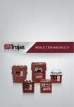
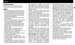
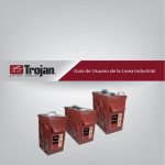
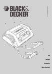
U S E R ’ S
G U I D E
Congratulations
on your purchase from Trojan Battery Company, the manufacturer of the
world’s most trusted deep-cycle batteries. The battery you purchased was
engineered by Trojan to deliver superior power, performance, durability
and reliability for use in a broad range of demanding applications. From the
T2 Technology™ in our flooded batteries to the C-Max Technology™ in the
Reliant™ AGM line, our goal is to provide clean and reliable energy storage
solutions that enhance the way people live and work around the world.
This User’s Guide
was created by Trojan’s application engineers and contains vital information
regarding proper care and maintenance of your new battery. Please read through
this User’s Guide carefully and completely before using your battery. It will help
you achieve optimum performance and long life from your new investment.
TECHNICAL SUPPORT
800-423-6569 Ext. 3045 / +1-562-236-3045
Contents
01Safety
02
03
. . . . . . . . . . . . . . . . . . 5
Equipment Needed . . . . . . . . . . .
5
Battery Installation . . . . . . . . . . .
6
3.1 Battery Connections . . . . . . . . . . . . . 6
How to Maximize the Performance of your Trojan Battery . . . . . . . . . . . . . . 24
07
What to Expect from your Trojan Battery . 25
08Trouble-Shooting .
. . . . . . . . . . . 26
3.2 Terminal Types . . . . . . . . . . . . . . . 6
8.1 Preparation for Testing . . . . . . . . . . . . 26
3.4 Cable Size . . . . . . . . . . . . . . . . 10
8.2 On-Charge Voltage Testing . . . . . . . . . . 26
3.5 Torque Values . . . . . . . . . . . . . . . 11
8.3 Specific Gravity . . . . . . . . . . . . . . 27
3.6 Terminal Protection . . . . . . . . . . . . . 12
8.4 Open Circuit Voltage Testing . . . . . . . . . 27
3.7 Connecting Batteries to Increase System Power . . 12
8.5 Discharge Testing . . . . . . . . . . . . . . 28
3.8 Ventilation . . . . . . . . . . . . . . . . 13
3.9 Battery Orientation . . . . . . . . . . . . . 13
3.10 Battery Environment . . . . . . . . . . . . 13
3.11 Temperature . . . . . . . . . . . . . . . 13
04
06
Preventative Maintenance . . . . . . . . 14
4.1 Inspection . . . . . . . . . . . . . . . . 14
4.2 Watering . . . . . . . . . . . . . . . . . 14
4.3 Cleaning . . . . . . . . . . . . . . . . . 16
4.4 Charging & Equalizing . . . . . . . . . . . . 16
4.4.1 Boost Charging . . . . . . . . . . . . . 16
4.4.2 Charging . . . . . . . . . . . . . . . . 18
4.4.3 Equalizing . . . . . . . . . . . . . . . 22
05Storage .
. . . . . . . . . . . . . . . . 24
5.1 Storage in Hot Environments . . . . . . . . . 24
5.2 Storage in Cold Environments . . . . . . . . . 24
09
Battery Recycling . . . . . . . . . . . . 29
10
Battery Acronyms . . . . . . . . . . . . 30
01 Safety
Since batteries deliver large amounts of power that can cause injury and even death, observing safety
rules is of paramount importance. For your safety and the safety of those around you, please observe the
following checklist when working on or around batteries.
Always
Never
Always wear protective clothes, gloves & safety goggles
Never smoke near batteries
Always use insulated tools when working on batteries
Never wear jewelry or other metal objects when working on
or around batteries
Always check connections for proper torque
Never make direct contact with the electrolyte (sulfuric acid). If this occurs,
flush with large amounts of water.
Always charge batteries in well-ventilated areas
Never place objects on top of batteries, which can cause a short circuit
Always keep sparks and flames* away from batteries
Never add acid to a battery
Always use largest cable size of shortest length to minimize voltage drop
Never charge a frozen battery
Always ensure plates are covered in water before charging
Never charge a flooded battery without securing vent caps on the cells
Always make sure charger is set for the appropriate battery type (flooded,
AGM or gel)
Never charge a battery when the temperature is above 122°F (50°C)
Always charge batteries before installing
Never store batteries unless they are fully charged
Always neutralize acid spills with baking soda and water
Never leave an acid spill unattended
W A R N I N G Risk of fire, explosion, or burns. Do not disassemble, heat above 70° C (160° F),
or incinerate.
E X C E P T I O N This statement may be included in the instructions provided with the
battery, rather than be marked on the battery.
02 Equipment Needed
Before installation or maintenance of your batteries, have the following equipment available:
îî
îî
îî
îî
îî
îî Voltmeter (deep-cycle flooded/wet, AGM and gel batteries)
îî Hydrometer (deep-cycle flooded/wet batteries)
îî Discharge tester (if available)
îî Battery charger
Proper personal protective equipment (eye protection and acid resistant gloves)
Distilled or treated water (i.e. de-ionized, reverse osmosis, etc.)
Insulated wrench
Baking soda
Terminal protector spray
U
S
E
R
’
S
G
U
I
D
E
5
03 Battery Installation
To ensure you install your batteries properly and safely, please use the following guidelines.
3.1 Battery Connections
Battery cables provide the link between the batteries, equipment and charging system. Faulty
connections can lead to poor performance and terminal damage, meltdown or fire. To ensure proper
connections, please use the following guidelines for cable size, torque values and terminal protection.
3.2 Terminal Types
Below are the various terminal types found on Trojan batteries. Refer to the appropriate terminal type
when determining proper torque in Section 3.5 below.
1
ELPT
2
Embedded Low
Profile
8
EHPT
3
Embedded High
Profile
AP
9
Automotive Post
EAPT
4
Embedded Auto
Post
WNT
10
Wingnut
EUT
Embedded
Universal
DWNT
11
Dual Wingnut
ST
5
LT
L-Terminal
14
Stud
IND
Industrial
6
DT
7
Automotive Post
& Stud
15
M6/M8
UT
Universal
15
6mm/8mm Insert
3.3 Correct Hardware* Installation
If using washers, it is very important to ensure the battery cable lug connection is contacting the lead
surface of the terminal, and the washer is placed on top of the wire connection. Do not place washer
between the terminal lead and the battery wire, which creates high resistance and can cause
terminal meltdown.
6
T
R
O
J
A
N
B
A T
T
E
R
Y
Flooded
ELPT
EUT
Cable Lug
Nut - Torque to 95-105 (in-lbs), 11-12 (Nm)
Washer*
Terminal
Bolt
Nut - Torque to 95-105 (in-lbs), 11-12 (Nm)
Washer*
Cable Lug
Terminal
EHPT
EAPT
Nut - Torque to 95-105 (in-lbs), 11-12 (Nm)
Washer*
Stud Portion
Terminal
AP Connector
AP Connector
Torque to 50-70 (in-lbs), 6-8 (Nm)
Terminal
Torque to 50-70 (in-lbs), 6-8 (Nm)
Cable Lug
DT
LT
Nut - Torque to 95-105 (in-lbs), 11-12 (Nm)
Washer*
Cable Lug
Bolt
Terminal
Cable Lug
Nut - Torque to 95-105 (in-lbs), 11-12 (Nm)
Washer*
AP Terminal
AP Connector
Torque to 50-70 (in-lbs), 6-8 (Nm)
Stud Terminal
IND
Cable Lug
Nut - Torque to 100-120 (in-lbs), 11-14 (Nm)
Washer*
Bolt
Terminal
Images shown reflect correct hardware placement. *Hardware not supplied by Trojan Battery Company.
U
S
E
R
’
S
G
U
I
D
E
7
AGM
LT
Nut - Torque to 70 (in-lbs), 8 (Nm)
Washer
Cable Lug
Bolt - 20 mm
M8 Terminal
Bolt - 16mm - Torque to 85-95 (in-lbs), 10-11 (Nm)
Lock Washer
LT Adapter
Lock Washer
ST
DT
Torque to 50-70 (in-lbs), 6-8 (Nm)
Washer
Stud Terminal
M8
Nut - Torque to 120-180 (in-lbs), 14-20 (Nm)
Cable Lug
Terminal
AP (RELIANT)
Nut - Torque to 95-105 (in-lbs), 11-12 (Nm)
Cable Lug
Lock Washer
APTerminal
AP Connector
Lock Washer
Bolt - Torque to 85-95 (in-lbs), 10-11 (Nm)
Washer
Cable Lug
Terminal
AP
AP Connector
Torque to 50-70 (in-lbs), 6-8 (Nm)
AP Connector
AP Adapter
Torque to 44-62 (in-lbs), 5-7 (Nm)
Torque to 85-95 (in-lbs), 10-11 (Nm)
M8 Terminal
Terminal
Images shown reflect correct hardware placement. All hardware supplied for Reliant AGM. Hardware for non Reliant AGM is optional.
8
T
R
O
J
A
N
B
A T
T
E
R
Y
Gel
LT
UT
Nut - Torque to 95-105 (in-lbs), 11-12 (Nm)
Cable Lug
Washer*
Terminal
Bolt
Washer*
Nut - Torque to 95-105 (in-lbs), 11-12 (Nm)
Terminal
Cable Lug
Bolt
DT
AP
Nut - Torque to 95-105 (in-lbs), 11-12 (Nm)
Cable Lug
Washer*
AP Terminal
AP Connector
AP Connector - Torque to 50-70 (in-lbs), 6-8 (Nm)
Terminal
Torque to 50-70 (in-lbs), 6-8 (Nm)
Stud Terminal
Images shown reflect correct hardware placement. *Hardware not supplied by Trojan Battery Company.
U
S
E
R
’
S
G
U
I
D
E
9
3.4 Cable Size
Battery cables should be sized to handle the expected load. Refer to Table 1 for the maximum amps
based on the cable/wire gauge size.
Table 1
10
Cable/Wire Gauge Size (AWG)
Ampacity (amps)
14
25
12
30
10
40
8
55
6
75
4
95
T
R
O
J
2
130
1
150
1/0
170
2/0
265
4/0
360
A
N
B
A T
T
E
R
Table values are for cable lengths
less than 6 feet (1829 mm). In
series/parallel battery banks, it
is preferable for all series cables
to be the same length, and all
parallel cables to be the same
length.
For more information refer to the
National Electric Code for correct
cable/wire size, which can be
located at www.nfpa.org.
Y
3.5 Torque Values
Tighten all cable connections to the proper specification to make sure there is good contact with the
terminals. Over-tightening terminal connections can cause terminal breakage and loose connections
can result in terminal meltdown or fire. Refer to Table 2 for the proper torque values based on the type of
terminal on your battery.
Table 2
Terminal Type
Torque (in-lb)
Torque (Nm)
95 - 105
11 - 12
Flooded
DWNT, ELPT, EUT, LT, UT, WNT
EAPT, AP
DT, EHPT
50 - 70
6-8
50 - 70 (AP Connector)
6 - 8 (AP Connector)
95 - 105 (Stud Portion)
11-12 (Stud Portion)
100 - 120
11 - 14
IND
AGM
M8
AP (Adapter) Reliant
85 - 95
10 - 11
50 - 70 (AP Connector)
6 - 7 (AP Connector)
95 - 105 (AP Adapter)
11 - 12 (AP Adapter)
44 - 62
5-7
50 - 70 (AP Connector)
6 - 8 (AP Connector)
95 - 105 (Stud Portion)
11-12 (Stud Portion)
70 (Nut)
6 - 8 (Nut)
AP
DT
LT (Adapter)
85 - 95 (Bolt)
10 - 11 (Bolt)
M6
30
3-4
ST
120 - 180
14 - 20
AP
50 - 70
6-8
LT, UT
95 - 105
11 - 12
50 - 70 (AP Connector)
6 - 8 (AP Connector)
95 - 105 (Stud Portion)
11-12 (Stud Portion)
Gel
DT
W A R N I N G Use an insulated wrench when making battery connections.
U
S
E
R
’
S
G
U
I
D
E
11
3.6 Terminal Protection
Corrosion can build up on terminals if they are not kept clean and dry. To prevent corrosion, apply a thin
coat of terminal protector spray that can be purchased through your local battery dealer.
3.7 Connecting Batteries to Increase System Power
EXAMPLE
You can increase capacity and voltage, or both, by configuring your batteries as follows:
Series Connect
Parallel Connect
Series/Parallel Connect
To increase voltage, connect batteries in
series. This will not increase the system
capacity.
To increase capacity, connect batteries
in parallel. This will not increase the
system voltage.
To increase both voltage and capacity,
connect additional batteries in series
and parallel.
Two T-105, 6V Batteries rated at 225AH
Connected in Series
Two T-105, 6V Batteries rated at 225AH
Connected in Parallel
Four T-105, 6V Batteries rated at 225A
Connected in Series/Parallel
Voltage 6V + 6V = 12V System
Capacity = 225AH
Voltage 6V System
Capacity = 225AH + 225AH = 450AH
Voltage 6V + 6V = 12V System
Capacity = 225AH + 225AH = 450AH
Call Tech Support for Additional Configurations
12
T
R
O
J
A
N
B
A T
T
E
R
Y
3.8 Ventilation
Deep-cycle flooded/wet lead acid batteries release small amounts of gas during usage, particularly
during the charging process. Deep-cycle AGM and gel batteries do release gas, but at a much lower rate
than the flooded types. It is critical to charge batteries in a properly ventilated area. For more assistance in
determining ventilation needs, please contact Trojan Battery Company’s technical support engineers.
3.9 Battery Orientation
Deep-cycle flooded/wet batteries must be placed upright at all times. Fluid in the battery will spill if the
battery is placed on its side or at an angle. Deep-cycle AGM or gel batteries are non-spillable and can be
placed either upright or on their side.
3.10 Battery Environment
Batteries should be stored and installed in a clean, cool and dry place, keeping water, oil, and dirt away
from the batteries. If any of these materials are allowed to accumulate on the batteries, tracking and
voltage leakage can occur, resulting in self-discharge and possible short-circuits. Battery chargers should
also be installed in well-ventilated, clean areas that are easily accessible.
3.11 Temperature
The recommended operating temperature range is between -4°F to 122°F (-20°C to +50°C) with a
humidity of <90%. Elevated battery electrolyte temperatures of >80°F (27°C) will reduce operating life,
while lower battery electrolyte temperatures of <80°F (27°C) will reduce battery performance.
It is important to minimize temperature variations between the cells, therefore, do not arrange the
batteries where they are too tightly packed together which restricts airflow. The batteries should have a
minimum of 0.50” (12.7 mm) of space between them to allow for adequate airflow.
U
S
E
R
’
S
G
U
I
D
E
13
04 Preventative Maintenance
4.1 Inspection
îî
îî
îî
îî
Examine the outside appearance of the battery. The tops of the batteries and terminal connections should be clean and dry, as well as free of dirt and corrosion. Refer to Cleaning Section 4.3.
If fluids are present on the top of a deep-cycle flooded/wet battery, it may mean that the battery is being over-watered or overcharged. Refer to Watering Section 4.2 for the proper watering procedure.
If fluid is present on the top of a deep-cycle AGM or gel battery, it may mean that the battery is being overcharged, which can reduce battery performance and life.
Check battery cables and connections. Replace any damaged cables and tighten any loose connections. Refer to Torque Values Section 3.5.
4.2 Watering (flooded/wet batteries only)
Deep-cycle flooded/wet batteries need to be watered periodically. The
frequency depends on battery usage, charging and operating temperature.
Check new batteries every few weeks to determine the watering frequency for
your application. It is normal for batteries to need more watering as they age.
Water should NEVER be added to deep-cycle AGM or gel batteries.
Standard Batteries
îî Fully charge the batteries prior to adding water. Only add water to
discharged or partially charged batteries if the plates are exposed. In this
case, add just enough water to cover the plates and then charge the
batteries. Once completed, continue with the watering procedure below.
îî Check the electrolyte levels by removing the vent caps and placing them
Plus Series™ batteries
upside down so that dirt does not accumulate on the underside of the cap.
For Plus Series™ batteries, simply flip open the cap.
îî If the electrolyte level is well above the plates, then it is not necessary to add more water.
îî If the electrolyte level is barely covering the plates, add distilled or de-ionized water to a level of
1/8” (3 mm) below the vent well. See right.
îî After adding water, secure vent caps back onto batteries.
îî Tap water may be used if the levels of impurities are within acceptable limits. Refer to Table 3 for Water
Impurity Limits.
14
T
R
O
J
A
N
B
A T
T
E
R
Y
Table 3
Recommended Maximum Allowable Impurities in Water for Battery Use
Parts Per Million
Effects of Impurity
Color
Impurity
Clear and “White”
-
Suspended Matter
Trace
-
Total Solids
100.00
Organic and Volatile Matter
50.0
Corrosion of positive plate
Ammonia
8.0
Slight self-discharge of both plates
Antimony
5.0
Increased self-discharge, reduces life, lower on-charge voltage
Arsenic
0.5
Self-discharge, can form poisonous gas at negative plate
Calcium
40.0
Increase of positive plate shedding
Chloride
5.0
Loss of capacity in both plates, greater loss on the positive plate
Copper
5.0
Increased self-discharge, lower on-charge voltage
Iron
3.0
Increased self-discharge at both plates, lower on-charge voltage
Magnesium
40.0
Reduced life
Nickel
None Allowed
Intense lowering of on-charge voltage
Nitrates
10.0
Increased sulfation on the negative plate
Nitrites
5.0
Corrosion of both plates, loss of capacity, reduced life
Platinum
None Allowed
Increased self-discharge, lower on-charge voltage
Selenium
2.0
Positive plate shedding
Zinc
4.0
Slight self-discharge of negative plate
-
U
S
E
R
’
S
G
U
I
D
E
15
4.3 Cleaning
Check the battery for cleanliness at regular intervals and keep terminals and connectors free of corrosion.
Terminal corrosion may adversely affect the performance of the battery and present a safety hazard.
îî
îî
îî
îî
îî
Check that all vent caps are secured properly on the battery.
Clean the top of the battery, terminals and connections with a cloth or brush, and a solution of baking soda and water (1 cup of baking soda to 1 gallon of water).
Do not allow cleaning solution to get inside the battery.
Rinse with water and dry with a clean cloth.
Apply a thin coat of terminal protector spray that can be purchased through your local battery dealer.
Keep the area around batteries clean and dry.
4.4 Charging & Equalizing
4.4.1 Boost Charging
The term boost charging refers to fully charging your batteries before they are used or when they are in
storage.
Flooded Batteries
Two methods can be used to boost charge flooded batteries, either automatically or manually. If
using the automatic method (charger is preprogrammed), simply allow the charger to go through the
complete charge cycle.
If you use the manual method (charger has adjustable settings) follow the steps below:
îî Boost charge at CONSTANT CURRENT, without voltage limit, at 3% of C₂₀ until the voltage stops increasing for three consecutive hourly readings. If using CONSTANT VOLTAGE, the recommended boost charge voltage is 2.58Vpc with the charger output current limited to 3 – 5% of C₂₀. The minimum recommended value is 2.45Vpc; however, this will result in an extended boost time.
îî The boost charge is not complete until the specific gravity readings of each cell remain constant over three successive hourly readings and all cells are gassing freely. If you have questions concerning boost charging, contact Trojan Battery Company Technical Support.
16
T
R
O
J
A
N
B
A T
T
E
R
Y
AGM / Gel Batteries
Similarly, two methods can be used to boost your AGM/gel product, automatically or manually. If using
the automatic method (charger is preprogrammed), just allow the charger to go through the complete
charge cycle. Make sure the proper battery type, AGM or gel, is selected on the charger.
If you use the manual method (charger has adjustable settings) follow the steps below:
îî Boost charge at a CONSTANT VOLTAGE of (2.40 VPC) with the current limited to 20% of C₂₀.
Example: 20 amps for a battery with a C₂₀ of 100Ah.
îî The time needed to boost charge the cells can be determined using the equation below.
Boost Charge Time in Hours =
DOD X Capacity at 20Hr Rate
Maximum Charge Current
+ 5 Hours
For example, a 100Ah battery taken down to a 25% depth of discharge (DOD) or 75% state of charge
(SOC) will need to be boost charged for 7½ hours with a 10A charger, or for 6¼ hours with a 20A charger.
U
S
E
R
’
S
G
U
I
D
E
17
4.4.2 Charging
Proper charging is imperative to maximize battery performance. Both under- or over-charging batteries
can significantly reduce the life of the battery. Most chargers are automatic and pre-programmed, while
others are manual and allow the user to set the voltage and current values.
AGM and gel batteries should always have temperature compensated charging.
îî Batteries should be fully charged after each use. “Use” is defined of at least 30 minutes
of runtime.
îî Deep-cycle flooded/wet charging guidelines: Refer to Table 4 and Diagram 4.
îî Deep-cycle AGM charging guidelines: There are various ways to charge AGM batteries. For optimum performance and life, Trojan recommends a 3-step profile as shown in Diagram 5 and following the guidelines in Table 5.
îî Deep-cycle gel charging guidelines: Refer to Table 6 and Diagram 6.
îî Before charging, make sure the charger is set to the appropriate program for deep-cycle flooded/wet, AGM or gel, depending on the type of battery you are charging.
îî Lead acid batteries (deep-cycle flooded/wet, AGM or gel) do not have a memory effect and therefore
and do not need to be fully discharged before recharging.
îî Charge only in well-ventilated areas.
îî Check electrolyte levels in deep-cycle flooded/wet batteries to make sure plates are covered with water before charging. Refer to Section 4.2.
îî Check that all vent caps are secured properly on the battery before charging.
îî Deep-cycle flooded/wet batteries will gas (bubble) towards the end of charge to ensure proper mixing of the electrolyte.
îî Never charge a frozen battery.
îî Avoid charging at temperatures above 122°F (50°C).
18
T
R
O
J
A
N
B
A T
T
E
R
Y
Table 4
Deep-Cycle Flooded/Wet Batteries - Charger Voltage Settings (@25°C, 77°F)
System Voltage
6 Volt
8 Volt
12 Volt
24 Volt
36 Volt
48 Volt
7.4
9.9
14.8
29.6
44.5
59.3
7.05 – 7.35
9.4 – 9.8
14.1 – 14.7
28.2 – 29.4
42.3 – 44.1
56.4 – 58.8
Finish Charge (2.70 VPC)
8.1
10.8
16.2
32.4
48.6
64.8
Equalize Charge (2.70 VPC)
8.1
10.8
16.2
32.4
48.6
64.8
Float Charge (if desired 2.25 VPC)
6.75
9.0
13.5
27
40.5
54
Bulk Charge (2.47 VPC)
Absorption Charge (2.35 – 2.45 VPC)
The chart below illustrates a typical recharge profile:
Diagram 4
Recommended Deep-Cycle Flooded/Wet Charging Profile
Voltage
(per cell)
Current
(Amps)
Charge Current
10-13% C20
2.45V to 2.70V
(@25°C, 77°F)
2.35V to 2.45V
(@25°C, 77°F)
Charge Voltage
1-3% C20
20%
90%
100%
State of Charge (%)
Note: Charging time will vary depending on battery size, charger output, and depth of discharge.
U
S
E
R
’
S
G
U
I
D
E
19
Table 5
Deep-Cycle AGM Batteries - Charger Voltage Settings**
System Voltage
6 Volt
8 Volt
12 Volt
24 Volt
36 Volt
48 Volt
7.2
9.6
14.4
28.8
43.2
57.6
6.75 – 6.9
9.4 – 9.8
14.1 – 14.7
28.2 – 29.4
42.3 – 44.1
56.4 – 58.8
Finish Charge (2.45 VPC)
7.35
9.8
14.7
29.4
44.1
58.8
Float Charge (2.25 – 2.3 VPC)
6.75
9.0
13.5
27
40.5
54
Bulk Charge (2.40 VPC)
Absorption Charge(2.35 – 2.45 VPC)
** AGM batteries should always use temperature compensated charging per the following rule:
5.0 mV per cell / °C or 2.8 mV per cell / °F
Subtract 0.005 volt per cell from the voltage reading for every 1°C above 25°C, or add 0.005 volt per cell for every 1°C
below 25°C. Subtract 0.0028 volt per cell for every 1°F above 77°F, or add 0.0028 volt per cell for every 1°F below 77°F.
The chart below illustrates a typical recharge profile:
Diagram 5
Recommended Trojan Deep-Cycle AGM Charging Profile
Voltage
(per cell)
Current
(Amps)
Charge Current
20% C20
2.35V to 2.45V
(@25°C, 77°F)
Charge Voltage
Approximately
C20/200
20%
80%
100%
State of Charge (%)
Note: Charging time will vary depending on battery size, charger output, and depth of discharge.
20
T
R
O
J
A
N
B
A T
T
E
R
Y
Will increase
with age
Table 6
Deep-Cycle Gel Batteries - Charger Voltage Settings**
System Voltage
6 Volt
8 Volt
12 Volt
24 Volt
36 Volt
48 Volt
Bulk Charge (2.40 VPC)
7.2
9.6
14.4
28.8
43.2
57.6
Float Charge (if desired 2.25 VPC)
6.75
9.0
13.5
27
40.5
54
** Gel batteries should always use temperature compensated charging per the following rule:
5.0 mV per cell / °C or 2.8 mV per cell / °F
Subtract 0.005 volt per cell from the voltage reading for every 1°C above 25°C, or add 0.005 volt per cell for every 1°C
below 25°C. Subtract 0.0028 volt per cell for every 1°F above 77°F, or add 0.0028 volt per cell for every 1°F below 77°F.
The chart below illustrates a typical recharge profile:
Diagram 6
Recommended Trojan Deep-Cycle Gel Charging Profile
Voltage
(per cell)
Current
(Amps)
Charge Current
10-13% C20
2.40V
(@25°C, 77°F)
Charge Voltage
20%
80%
100%
State of Charge (%)
Note: Charging time will vary depending on battery size, charger output, and depth of discharge.
U
S
E
R
’
S
G
U
I
D
E
21
4.4.3 Equalizing (deep-cycle flooded/wet batteries only)
Equalizing is an overcharge performed after fully charging deep-cycle flooded/wet batteries. An
equalizing charge prevents battery stratification and reduces sulfation which are leading causes of
battery failure. Trojan recommends equalizing every 30 days or when batteries have a low specific
gravity reading after fully charging, below 1.235, or have a wide ranging specific gravity of >0.030 points
between cells.
Deep-cycle AGM or gel batteries should NEVER be equalized.
Equalization can be performed either automatically (as programmed on the charger) or by following the
procedure below:
îî
îî
îî
îî
îî
Check the battery’s electrolyte level in each cell to make sure the plates are covered before charging.
Check that all vent caps are secured properly on the battery before charging.
Set charger to equalizing mode.
The batteries will gas (bubble) during the equalization process.
Measure the specific gravity every hour. Refer to Table 7 for specific gravity and voltage measurements. Discontinue the equalization charge when the specific gravity no longer rises.
W A R N I N G Do not equalize deep-cycle AGM or gel batteries.
22
T
R
O
J
A
N
B
A T
T
E
R
Y
Table 7
Flooded/Wet State of Charge as a Measure of Specific Gravity and Open-Circuit Voltage
Percentage Charge
Specific Gravity
Cell
6 Volt
8 Volt
12 Volt
100
1.277
2.122
6.37
8.49
12.73
90
1.258
2.103
6.31
8.41
12.62
80
1.238
2.083
6.25
8.33
12.50
70
1.217
2.062
6.19
8.25
12.37
60
1.195
2.04
6.12
8.16
12.24
50
1.172
2.017
6.05
8.07
12.10
40
1.148
1.993
5.98
7.97
11.96
30
1.124
1.969
5.91
7.88
11.81
20
1.098
1.943
5.83
7.77
11.66
1.073
1.918
5.75
7.67
11.51
10
AGM State of Charge as a Measure of Open-Circuit Voltage
Percentage Charge
Specific Gravity
Cell
6 Volt
8 Volt
12 Volt
100
NA
75
NA
2.14
6.42
8.56
12.84
2.09
6.27
8.36
12.54
50
NA
2.04
6.12
8.16
12.24
25
NA
0
NA
1.99
5.97
7.96
11.94
1.94
5.82
7.76
11.64
Gel State of Charge as a Measure of Open-Circuit Voltage
Percentage Charge
Specific Gravity
Cell
6 Volt
8 Volt
12 Volt
100
NA
75
NA
2.14
6.42
8.56
12.84
2.11
6.33
8.44
12.66
50
NA
2.06
6.18
8.24
12.36
25
NA
2.00
6.00
8.00
12.00
0
NA
1.97
5.91
7.88
11.82
U
S
E
R
’
S
G
U
I
D
E
23
05 Storage
îî
îî
îî
îî
îî
îî
Charge batteries before placing in storage.
Store in a cool, dry location, protected from the elements.
Disconnect from equipment to eliminate potential parasitic loads that may discharge the battery.
Batteries gradually self-discharge during transit and storage, so monitor the specific gravity or voltage in flooded batteries every 4 - 6 weeks. Monitor the open circuit voltage for AGM or gel batteries every
2 - 3 months.
Batteries in storage should be given a boost charge when they are at 70% SOC for flooded and 75% for AGM or gel. Refer to Table 7 for specific gravity (flooded only) and voltage measurements for flooded batteries and AGM or gel batteries. If boosting is needed, refer to Section 4.4.1 for boosting instructions.
When batteries are taken out of storage, recharge before use.
5.1 Storage in Hot Environments (greater than 90°F or 32°C)
Avoid direct exposure to heat sources, if possible, during storage. Batteries self-discharge faster in high
temperatures. If batteries are stored during hot summer months, monitor the specific gravity or voltage
more frequently (approximately every 2 - 4 weeks).
5.2 Storage in Cold Environments (less than 32°F or 0°C)
Avoid locations where freezing temperatures are expected, if possible, during storage. Batteries can
freeze in cold temperatures if they are not fully charged. If batteries are stored during cold winter
months, it is critical that they are kept fully charged at all times.
06 How to Maximize the Performance of your Trojan Battery
îî
îî
îî
24
T
Follow all the procedures in this User’s Guide for proper installation, maintenance and storage.
Do not discharge your battery more than 80%. This safety factor will eliminate the chance of over-
discharging and damaging your battery.
If you have any questions or concerns about battery care, please contact Trojan Battery Company’s technical support engineers at 800-423-6569 Ext. 3045 or +1-562-236-3045 before a
problem develops.
R
O
J
A
N
B
A T
T
E
R
Y
07 What to Expect from your Trojan Battery
îî
îî
îî
îî
îî
îî
A new deep-cycle battery will not immediately deliver its full rated capacity. This is normal and should be expected since it takes time for a deep-cycle battery to reach maximum performance or peak capacity.
Trojan’s deep-cycle AGM and gel batteries will reach rated capacity in less than 10 cycles.
Trojan’s deep-cycle flooded batteries take between 50 – 100 cycles to achieve full, peak capacity.
When operating batteries at temperatures below 80°F (27°C), they will deliver less than the rated capacity. For example at 0°F (-18°C) the battery will deliver 50% of its capacity and at 80°F (27°C) it will deliver 100% of its capacity.
When operating batteries at temperatures above 80°F (27°C), they will deliver more than the rated capacity but will reduce battery life.
The life of a battery is difficult to predict and will vary by application, frequency of usage and
level of maintenance.
60
120
50
100
40
30
80
20
60
10
40
0
20
Temperature (C)
Temperature (F)
Capacity vs. Temperature
140
-10
0
-20
-20
-30
-40
-40
0%
20%
40%
60%
80%
100%
120%
Percent of Available Capacity
U
S
E
R
’
S
G
U
I
D
E
25
08 Trouble-Shooting
These battery testing procedures are guidelines only for identifying a deep-cycle battery that may need
to be replaced. Unique situations may be observed that are not identified within this procedure. Please
contact Trojan Battery Company’s technical support engineers at 800-423-6569 Ext. 3045 or +1-562-2363045 for help interpreting the test data.
8.1 Preparation for Testing
îî
îî
îî
îî
îî
Check that all vent caps are secured properly on the battery.
Clean the top of the battery, terminals and connections with a cloth or brush and a solution of baking soda and water (1 cup of baking soda to 1 gallon of water). Do not allow cleaning solution to get inside the battery. Rinse with water and dry with a clean cloth.
Check battery cables and connections. Replace any damaged cables. Tighten any loose connections with an insulated wrench. Refer to Torque Values Section 3.5.
For deep-cycle flooded/wet batteries, check the electrolyte level and add water if necessary. Refer to Watering Section 4.2.
Ensure batteries are fully charged before discharge testing to obtain accurate results.
8.2 On-Charge Voltage Testing
îî
îî
îî
îî
îî
îî
26
T
Disconnect and reconnect DC plug to restart charger.
While the batteries are on-charge, record the current in the last ½ hour of charge cycle (if possible), and measure the battery set voltage.
If the current at the end of the charge is below 5 amps, and the battery set voltage is above the following readings, proceed to the next step:
îî 56V for a 48V system
îî 42V for a 36V system
îî 28V for a 24V system
îî 14V for a 12V battery
îî 9.3V for a 8V battery or 7V for a 6V battery
If the current at the end of the charge does not match these readings, check the charger for proper output and recharge the batteries. If the set voltages are still low, you may have a failed battery.
While the batteries are on-charge, measure the individual battery voltages.
If any battery voltage is below 7V for 6V battery, 9.3V for 8V battery and 14V for 12V battery, and a voltage variation is greater than 0.5V for 6V battery or 1.0V for a 12V battery, from any other battery in set, it may be a failed battery.
R
O
J
A
N
B
A T
T
E
R
Y
8.3 Specific Gravity (flooded/wet batteries only)
îî Fill and drain the hydrometer 2 - 3 times before drawing a sample from the battery.
îî Measure specific gravity readings for all battery cells.
îî Correct specific gravity readings for temperature by adding 0.004 for every 10°F (5°C) above 80°F (27°C), and subtract 0.004 for every 10°F (5°C) below 80°F (27°C).
îî If every cell in the battery set is below 1.235, the batteries may be undercharged and require recharging.
îî If any battery has a specific gravity variation of more than 0.030 between cells, equalize the set.
îî If there is still a variation there may be a failed battery.
8.4 Open Circuit Voltage Testing
This is the least preferred method of evaluating the condition of a deep-cycle flooded/wet battery, but is
the only method for AGM and gel batteries.
îî For accurate voltage readings, batteries must remain idle at least 6 hours, preferably up to 24 hours.
îî Measure the individual battery voltages.
îî If any battery voltage is greater than 0.3V compared to other batteries in set, equalize the set (deep- cycle flooded/wet batteries ONLY). Refer to Equalizing Section 4.4.3.
îî Measure the individual battery voltages again.
îî If any battery voltage is still greater than 0.3V compared to any other battery in the set, you may have a failed battery.
U
S
E
R
’
S
G
U
I
D
E
27
8.5 Discharge Testing
îî
îî
îî
îî
Follow the procedure below to determine battery capacity.
Connect and start discharger.
Record the runtime (minutes) when discharge is complete.
Correct runtime minutes for temperature using the following formula (valid between 75°F (24°C) and 90°F (32°C):
Mc = Mr [1 – 0.005* (T1 - 80*)] *(For Celsius, use 0.009 & 27°C)
Where Mc = Discharge time corrected to 80°F (or 27°C)
Mr = Actual discharge time
T1 = Battery temperature at end of discharge (°F or °C)
îî
îî
îî
If the discharge runtime is greater than 50% of the batteries’ rated capacity at that discharge rate, then all the batteries are operational.
Restart the discharger to record the individual battery voltage while still under load
(current being drawn).
If the discharge runtime is less than 50% of the batteries’ rated capacity, the battery with a voltage that is 0.5V lower than the highest voltage may be a failed battery.
There are other methods of testing batteries including internal resistance (i.e. C.C.A. testers) and carbonpile discharge testers. However these are not suitable testing methods for deep-cycle batteries.
28
T
R
O
J
A
N
B
A T
T
E
R
Y
09 Battery Recycling
Lead acid batteries are the environmental success story of our time since more than 97% of all battery
lead is recycled. In fact, lead acid batteries top the list as one of the most highly recycled consumer
products. Trojan Battery supports proper recycling of your battery to keep the environment clean.
Please contact your nearest Trojan Distributor, at www.trojanbattery.com, to learn how to properly
recycle your batteries.
Below is the process in which your Trojan battery will be recycled:
Transportation
Recycling For A
Better Environment
Plastic
Plastic pellets recycled from
battery cases and covers are
used to manufacture new
cases and covers
Crush the case
and covers
Lead
Lead ingots recycled from
battery grids, other battery
parts (e.g., posts and terminals)
and lead-oxide are used to
manufacture lead for new
grids, parts, and lead oxide
Melt grids
The same network that distributes
new batteries also safely collects and
returns used batteries for recycling
At the recycling facility, used batteries are
broken apart and separated into components
to begin the recycling process
Electrolyte: Option 1
Electrolyte: Option 2
Sodium sulfate crystals
separated from used electrolyte
(dilute sulfuric acid) is recycled
and sold for use in textiles,
glass and detergent
manufacturing
At some recyclers, used
electrolyte is reclaimed and
reused in manufacturing new
batteries. At others, it is
neutralized and managed
according to federal and state
water permits
Neutralize
electrolyte
Lead ingots
Plastic pellets
New Grids and
Lead Oxide
New Covers
and Cases
New battery covers and cases
are manufactured using
recycled plastic pellets
Sodium
sulfate
crystals
New battery grids are
manufactured from recycled
lead. Recovered lead oxide
is also used in new
battery manufacturing
New grids
Lead Oxide
New cases
and covers
OR
Electrolyte
is neutralized
and sent to
a water
treatment
plant
Glass, textiles,
detergent
Electrolyte
is chemically
treated and
reused
New Battery
Graphics provided by Battery Council International
U
S
E
R
’
S
G
U
I
D
E
29
10 Battery Acronyms
AGM
°FFahrenheit
Absorbed Glass Mat
AMPAmperage
IND AHAmp-Hours
LT L-Terminal
AWG
American Wire Gauge
M6/M8
6mm - 8mm Teminal
AP Automotive Post Terminal
Industrial Terminal
Mc
Corrected Minutes
°CCelsius
Mr
Minutes Recorded
C.C.A.
Cold Cranking Amps
SOC
State of Charge
DT Automotive Post & Stud Terminal
ST Stud Terminal
DWNT Dual Wingnut Terminal
TTemperature
EAPT Embedded Automotive Post Terminal
UT EHPT Embedded High Profile Terminal
VVolt
ELPT Embedded Low Profile Terminal
WNT
EUT Embedded Universal Terminal
Notes
30
T
R
O
J
A
N
B
A T
T
E
R
Y
Universal Terminal
Wingnut Terminal
Trojan Battery Company
would like to thank you for selecting our battery. With over 85 years of experience, Trojan Battery is the
world’s most trusted name in deep-cycle battery technology backed by our outstanding technical
support. We look forward to serving your battery needs.
T R O J A N B AT T E R Y C O M PA N Y
12380 Clark Street, Santa Fe Springs, CA 90670 USA
Call 8 0 0 - 423 - 6569 E x t . 30 45 or +1-562-236 -30 45
or V isit w w w.trojanb at ter y.com
This publication is protected by copyright and all rights are reserved. No part of it may be reproduced or transmitted by any means or in any form, without
prior consent in writing from Trojan Battery Company.
Trojan Battery Company is not liable for direct, indirect, special, exemplary, incidental or consequential damages that may result from any information
provided in or omitted from this manual, under any circumstances.
Trojan Battery Company reserves the right to make adjustments to this manual at any time, without notices or obligation.
Trojan Battery Company and the Trojan Battery logo are registered trademarks of Trojan Battery Company.
T2 Technology, C-Max Technology, Reliant AGM, and Plus Series are trademarks of Trojan Battery Company in the United States and other countries.
U
S
E
R
’
S
G
U
I
D
E
31
Trojan batteries are available worldwide
through Trojan’s Master Distributor
Network. We offer outstanding technical
support, provided by full-time
application engineers.
t r o j a n b a t t e r y. c o m
800.423.6569 or + 1.562.236.3000
12380 Clark Street, Santa Fe Springs, CA 90670 • USA
© 2015 Trojan Battery Company. All rights reserved. Trojan Battery Company is not liable for damages that may result from any information provided in or omitted from this publication, under any circumstances. Trojan Battery Company reserves
the right to make adjustments to this publication at any time, without notices or obligation. Please check the Trojan Battery website (www.trojanbattery.com) for the most up-to-date information.
Users Guide EN 2015_0812