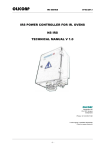
1
SC5000 System View Version 3.42 and up Operation Manual 2004 Mercury Marine 90-895200 MARCH 2004 CONTENTS Section 1 - Introduction Section 2 - Getting Started • Starting Up the System View • Display Screens Section 3 - Propulsion • Engine RPM and Speed • Engine RPM Synchronizer – Twin Engines • Engine Data Screens • Supercharger Boost • Trim Position • Troll Control • Peak Speed at RPM Section 4 - Vessel • Steering Position • Fuel, Water, and Waste Tank Level Status • Vessel Status Data • Estimated Fuel Range Section 5 - Navigation • Vessel Course • Next Waypoint • Trip History • Depth • Air Temperature • Seawater Temperature Section 6 - Settings • Contrast/Lighting/Clock • Units/Language/Offsets • Home Page Data • Sensors • Preferences • Favorites/Page Status INTRODUCTION 1 GETTING STARTED 2 PROPULSION 3 VESSEL 4 NAVIGATION/FUEL 5 SETTINGS 6 SYSTEMS INSTALLATION A to Z INDEX 7 8 9 Section 7 - Systems • System Calibration • Maintenance Log • Active Alarms • Alarm History Section 8 - Installation • System View Installation • Wiring Information Section 9 - Index 2004 Mercury Marine 90-895200 MARCH 2004 INTRODUCTION Introduction The SC5000 System View Display is a comprehensive boat information center. System View allows the boat operator to receive a wealth of critical operational information, displayed clearly and instantly at the helm on the LCD display. The System View continuously monitors and reports information ranging from basic operating data to detailed vessel environment information. System View covers water temperature and depth, engine trim status, boat speed, steering angle, system preventive maintenance reminders and systems diagnostics. System View also can be fully integrated with the boat’s GPS, if equipped, to provide up to the minute course, speed, and fuel-to-destination information. System View Displays Detailed Information in These Important Categories: NOTE: The detailed information listed which is standard on some models may be optional on others, or may not be available on some models based on engine and system configuration. Propulsion Information Section 3 • Engine rpm combined with boat speed • Twin engine synchronizer display • Peak boat speed in conjunction with peak engine RPM • Engine data screens • Supercharger boost • Troll control • Trim position Vessel Information Section 4 • Steering angle display • Fuel tank, oil tank, water tank, and waste water tank level display • Vessel status • Estimated fuel range Navigation Section 5 • Direction to target waypoint information shows present course and current speed on a graphic compass rose • Shows distance, time, speed, and fuel to next waypoint • Resettable trip history shows miles per hour, miles per gallon, elapsed drive time, and amount of fuel consumed on current trip • Water depth with depth history graph • Sea water temperature with temperature history graph Alarm, Diagnostic, and Maintenance Information Section 7 • Displays alarms and helpful information concerning alarm causes • Log recorder for periodic propulsion maintenance 90-895200 MARCH 2004 Page 1-1 1 INTRODUCTION Keypad Usage SYSTEM VIEW • Arrow trackpad – Can be used to operate the up and down and side to side movement for System View on-screen function promps. • Select key – Is used to select screen options and confirm data entry. • Home key – The HOME (power) key has two different functions: a. Pressing the home key will return the System View display back to the home page directory. b. The HOME key can be used to power-up or turn off the System View. Pressing and holding in the home key for 3 seconds with key switch turned off will power-up or turn off the System View. a b c a - Arrow trackpad b - Select key c - Home key CONSOLE REMOTE CONTROLS – ELECTRONIC THROTTLE AND SHIFT MODELS 1. Arrow trackpad – Can be used to operate the up and down and side to side movement for System View on-screen function promps. 2. Select key – Can be used to select System View on-screen options and confirm data entries. Pressing the Select switch for 2 seconds will return the System View display back to the Home page. a b a b a - Arrow trackpad b - Select key Page 1-2 90-895200 MARCH 2004 GETTING STARTED GETTING STARTED Section 2 Table of Contents Starting up the System View . . . . . . . . . . . . . . . . . . . . . . . . . . . . . . . . . . . . . . . . . . . . . . . . . Display Screens . . . . . . . . . . . . . . . . . . . . . . . . . . . . . . . . . . . . . . . . . . . . . . . . . . . . . . . . . . . . Start-up Screens . . . . . . . . . . . . . . . . . . . . . . . . . . . . . . . . . . . . . . . . . . . . . . . . . . . . . . . . Home Page Screen . . . . . . . . . . . . . . . . . . . . . . . . . . . . . . . . . . . . . . . . . . . . . . . . . . . . . . Data Display Screens . . . . . . . . . . . . . . . . . . . . . . . . . . . . . . . . . . . . . . . . . . . . . . . . . . . . Alarm Message Screens . . . . . . . . . . . . . . . . . . . . . . . . . . . . . . . . . . . . . . . . . . . . . . . . . . 90-895200 MARCH 2004 2 2-2 2-2 2-2 2-3 2-5 2-9 Page 2-1 GETTING STARTED Starting Up the System View Turning on the main engine switch will start up the System View. The System View will move through a sequence of start-up screens shown below. Pressing SELECT will pause the screen. Display Screens Start-Up Screens The start-up screens can be set to display home page (Step 1) or the last display shown before power off (Step 2). To select a setting, refer to “Setting/Preferences/Start-up Page” menu in Section 6. 1. Start-up screens will appear in sequence ending at the home page. 2. If set by owner, start-up screens will appear in sequence to the last display viewed before powering down. 3. Calibration screen – This screen only appears if initial setup calibration has not been performed. Press SELECT to perform calibration procedures. Please refer to System Calibration located in the SmartCraft System View installation instructions provided with the System View or engine service manual. 1 Page 2-2 2 3 90-895200 MARCH 2004 GETTING STARTED Display Screens Home Page Screen Across the bottom half of the home page you will find six on-screen main directory selections. Use the trackpad to highlight the directory choice. Press SELECT to accept your choice and to open the directory screen. NAVIGATION (See Section 5) PROPULSION (See Section 3) • Direction to target waypoint information • Engine RPM combined with boat speed • Twin engine synchronizer display • Peak boat speed in conjunction with • • • • shows present course and current speed on a graphic compass rose Shows distance, time, bearing, and fuel to next waypoint Resettable trip history shows miles per hour, miles per gallon, elapsed drive time and amount of fuel consumed on current trip Water depth with depth history graph Sea water temperature • • • • peak engine RPM Engine data Troll control Trim position Supercharger boost FAVORITES (See Section 6) VESSEL (See Section 4) • Steering angle display (sensor on Sterndrive• Collection of Screens Selected • models only) Fuel tank, water tank, and waste water tank level display Vessel information by the User • • Estimated fuel range SYSTEM (See Section 7) SETTINGS (See Section 6) • • • • • • 90-895200 MARCH 2004 Contrast/Lighting/Clock Units/Language/Offsets Sensors Favorites/Page Status Home page data preferences • • • • Maintenance Log Active Alarms Alarm History System Calibration Page 2-3 GETTING STARTED Display Screens Home Page Screen (Continued) The top half of the home page displays engine data and vessel data. The engine data is received from sensors on the engine and the vessel data is received by vessel sensors. The initial screen layout takes one of two forms depending on whether one or two engines are installed. Defaults for the engine data include engine RPM and engine temperature. Default for vessel data is water depth. The data displays can be selected by the user to display the functions. Refer to “Settings/ Preferences/Home Page Data” Menu in Section 6. TWIN ENGINE DISPLAY SINGLE ENGINE DISPLAY 7 6 3 4 5 1 4 1 2 1 RPM H20 PSI ENG TEMP Oil PSI Oil TEMP FUEL FLOW 1 2 3 4 5 6 7 Page 2-4 3 2 RPM H20 PSI ENG TEMP Oil PSI Oil TEMP FUEL FLOW 5 2 3 VOLTS SPEED DEPTH FUEL LEVEL RANGE AIR TEMP SEA TEMP DTW COG SOG BTW COG/BTW - Engine Line 1 – Refer to Section 6 for selection - Engine Line 2 – Refer to Section 6 for selection - Vessel Data – Refer to Section 6 for selection - Engine gear position or run arrow - Clock – Refer to Section 6 for setting - Flashing Bell Icon – Warning alarm is activated - Flashing Fuel Icon – Low fuel alarm 90-895200 MARCH 2004 GETTING STARTED Display Screens Data Display Screens The data display screens can be selected from the main directory menu choices which are selected from the home page. The current directory menu selection icon is displayed in top-left of the display. The presentation of information on-screen will be shown in the information window located at the bottom on the screen. Alarm Notice – When a problem is detected, the name of the offending alarm will appear in the information window and a bell symbol at the bottom of the screen flashes. The bell symbol will continue to flash as long as the alarm condition is still present. If there are multiple alarms, these will cycle on the display screen. 1 Directory Menu Indicator Icon Propulsion Vessel Navigation/Fuel 4 Settings System Home 3 Alarm Notice Alarm Notice 2 Normal Operation 1 2 3 4 90-895200 MARCH 2004 - Directory identification icon - Alarm window - Information window - Display screen Page 2-5 GETTING STARTED Display Screens Data Display Screens Glossary Data Screen Directory Location Engine Data Screens Engine data screens are a group of displays showing various engine data. Engine RPM and Speed Displays engine RPM and boat speed. Engine RPM Synchronizer Twin Engines – Displays the difference in engine speed (RPM) between the port and starboard engines Peak Speed at RPM This screen records the top speed the boat reached and associated engine rpm as measured since the last reset. Trim Position Display indicates the propulsion unit position achieved by setting trim and trailer position. Troll Control Maintain a trolling speed without using the throttle. Supercharger Boost Displays the supercharge boost of supercharged engines. Page 2-6 90-895200 MARCH 2004 GETTING STARTED Display Screens Data Display Screens Glossary Data Screen Directory Location Steering Position Displays steering position in degrees. Tank Status Shows level of the vessel’s tanks. Tank Levels Displays the level of each tank. Vessel Status Displays engine run time Total fuel remaining Additional tank levels Air temperature Estimated Fuel Range Displays estimated range and fuel remaining, as well as current total fuel flow. Trip History Log Displays average fuel economy, average boat speed, total drive time, along with a corresponding distance traveled and fuel used. 90-895200 MARCH 2004 Page 2-7 GETTING STARTED Display Screens Data Display Screens Glossary Data Screen Directory Location Depth Displays the depth of water. Depth Plot Line Displays a plot line of depth vs. time as recorded over the last 16 seconds. Environment Displays speed, depth, air temperature, and sea water temperature. Navigation Screen 1 Displays a compass and shows direction to a targeted waypoint. Navigation Screen 2 Displays navigating data to a waypoint. Seawater Temperature Plot LIne Displays a plot line of seawater temperature vs. time as recorded over the last 80 seconds. Also displays the current water temperature. Page 2-8 90-895200 MARCH 2004 GETTING STARTED Display Screens Alarm Message Screens When a problem is detected, the System View will alert the operator. Use the following steps to determine the cause of the problem: 1. A pop-up screen will appear displaying an alarm message. If there are multiple alarms, the display will show the last alarm activated. 2. Press SELECT to clear the pop-up screens and return back to the display screen that was being viewed. Bell icon will now be flashing and alarm message will be displayed on the bottom of the screen. 3. A number of different problems may be grouped together under one alarm message. To determine the exact cause of the problem, return back to the home page and access the SYSTEM directory. The SYSTEM directory will show the active alarms causing the problem. 4. Refer to the “Active Alarms” in Section 7 or the Engine Operation, Maintenance Manual for further explanation of the problem and the correct action to take. If the problem can cause immediate engine damage, the engine guardian system will respond to the problem by limiting engine power. 2 1 3 90-895200 MARCH 2004 Page 2-9 PROPULSION PROPULSION Section 3 Table of Contents Propulsion Information . . . . . . . . . . . . . . . . . . . . . . . . . . . . . . . . . . . . . . . . . . . . . . . . . . . . . . Entering the Propulsion Directory . . . . . . . . . . . . . . . . . . . . . . . . . . . . . . . . . . . . . . . . . . . . . Propulsion Data Screens . . . . . . . . . . . . . . . . . . . . . . . . . . . . . . . . . . . . . . . . . . . . . . . . . . . . Engine RPM/Speed . . . . . . . . . . . . . . . . . . . . . . . . . . . . . . . . . . . . . . . . . . . . . . . . . . . . . . Peak Speed at RPM . . . . . . . . . . . . . . . . . . . . . . . . . . . . . . . . . . . . . . . . . . . . . . . . . . . . . Engine RPM Synchronizer – Twin Engines . . . . . . . . . . . . . . . . . . . . . . . . . . . . . . . . . . Engine Data Screens . . . . . . . . . . . . . . . . . . . . . . . . . . . . . . . . . . . . . . . . . . . . . . . . . . . . Trim Position . . . . . . . . . . . . . . . . . . . . . . . . . . . . . . . . . . . . . . . . . . . . . . . . . . . . . . . . . . . Supercharger Boost . . . . . . . . . . . . . . . . . . . . . . . . . . . . . . . . . . . . . . . . . . . . . . . . . . . . . . Troll Control . . . . . . . . . . . . . . . . . . . . . . . . . . . . . . . . . . . . . . . . . . . . . . . . . . . . . . . . . . . . . 90-895200 MARCH 2004 3-2 3-2 3-3 3-3 3-3 3-4 3-4 3-5 3-5 3-6 3 Page 3-1 PROPULSION Propulsion Information This Section will give a complete description of the display screens in the PROPULSION directory of the System View. Some of the propulsion functions are: • Troll control • Engine RPM combined with boat speed • Twin engine synchronizer display • Peak boat speed in conjunction with peak engine RPM • Trim position • Engine data screens • Supercharger boost Entering the Propulsion Directory To access the PROPULSION directory, use the trackpad to highlight the PROPULSION directory from the menu choice. Press SELECT to accept and to open the directory. Page 3-2 90-895200 MARCH 2004 PROPULSION Propulsion Data Screens Engine RPM/Speed This screen displays engine speed (RPM) and boat speed. TWIN ENGINE SINGLE ENGINE 1 1 - Speed Sensors – This window shows the sensor that is currently sending the speed signal. The speed sensor is automatically selected based on what sensors are available. Peak Speed at RPM This screen records the top speed the boat reached and associated engine RPM as measured since the last reset. To Reset the Peak Speed and corresponding RPM, press and hold the SELECT button momentarily. TWIN ENGINE SINGLE ENGINE 1 1 - Speed Sensors – This window shows the sensor that is currently sending the speed signal. The speed sensor is automatically displayed based on what sensors are available. 90-895200 MARCH 2004 Page 3-3 PROPULSION Propulsion Data Screens Engine RPM Synchronizer – Twin Engine This screen displays the difference in engine speed (RPM) between the port and starboard engines. Allows throttle adjustments to keep each engine running uniformly. Starboard Engine Port Engine Engine Data Screens Engine data screens are a group of displays showing various engine data. NOTE: Not all screens listed may be available for your type of engine. 1. ENGINE TEMP (Temperature) – Displays engine temperature. The temperature will vary with air temperature, water temperature and operating conditions. 2. H20 PRESSURE (Water) – Displays engine water pressure when engine is running. 3. BATTERY – Displays battery voltage level (condition) of battery. 4. FUEL FLOW – Displays current estimated engine fuel consumption in U.S. Gallons per hour (Gal/hr) or Liters per hours (Ltr/hr). 5. OIL PRESSURE – Displays engine oil pressure when the engine is running. The oil pressure may vary with engine speed, outside temperature and oil viscosity. While the engine is warming up, the oil pressure will be higher than when the engine is at normal operating temperature. 1 4 2 5 3 Page 3-4 90-895200 MARCH 2004 PROPULSION Propulsion Data Screens Trim Position Display indicates the propulsion unit position achieved by setting trim and trailer position. SINGLE ENGINE TWIN ENGINE Supercharger Boost Displays the supercharger boost of supercharged engines. SINGLE ENGINE 90-895200 MARCH 2004 TWIN ENGINE Page 3-5 PROPULSION Propulsion Data Screens Troll Control NOTE: Depending on your engine type, Troll Control feature may not be available. TWIN ENGINE SINGLE ENGINE BASIC OPERATION IMPORTANT: User must maintain constant helm control while using troll control to avoid obstacles. With troll control, you can maintain a trolling speed within a range specific to engine type without using the throttle. You must stay in the troll control screen while using troll control. If you leave the troll control screen, troll will automatically disengage. You can shut off troll control anytime by pushing SELECT, moving the throttle, or shifting engine into neutral. NOTE: Avoid using a very low rpm trolling speed for an extended period of time. Doing so could result in a low-battery voltage condition. SETTING TROLL CONTROL 1. Press to display the TROLL CONTROL display screen. 2. With the engine running, shift engine into gear. 3. Set engine speed at idle. 4. Single Engine – Press SELECT to engage (turn on) the troll control. Twin Engine – Press SELECT to choose which engine is to be in troll control. Press to select STBD, PORT, or BOTH. Flashing “Selected” indicates chosen engine. Press SELECT a second time to engage troll control. 5. Press to set desired RPM. NOTE: On dual station installations (2 System Views), you can hand-off the current troll control configuration from the troll control screen from one unit to the other by pressing SELECT to engage on the opposite unit. TURNING OFF TROLL CONTROL There are three ways to turn off the troll control: Page 3-6 • Press SELECT • Move the throttle to a different speed • Shift engine into neutral 90-895200 MARCH 2004 VESSEL VESSEL Section 4 Table of Contents Vessel Information . . . . . . . . . . . . . . . . . . . . . . . . . . . . . . . . . . . . . . . . . . . . . . . . . . . . . . . . . . Entering the Vessel Directory . . . . . . . . . . . . . . . . . . . . . . . . . . . . . . . . . . . . . . . . . . . . . . . . Vessel Data Screens . . . . . . . . . . . . . . . . . . . . . . . . . . . . . . . . . . . . . . . . . . . . . . . . . . . . . . . Steering Position . . . . . . . . . . . . . . . . . . . . . . . . . . . . . . . . . . . . . . . . . . . . . . . . . . . . . . . . Tank Status . . . . . . . . . . . . . . . . . . . . . . . . . . . . . . . . . . . . . . . . . . . . . . . . . . . . . . . . . . . . . Fuel Tanks . . . . . . . . . . . . . . . . . . . . . . . . . . . . . . . . . . . . . . . . . . . . . . . . . . . . . . . . . . . . . . Water and Waste Tanks . . . . . . . . . . . . . . . . . . . . . . . . . . . . . . . . . . . . . . . . . . . . . . . . . . Vessel Status . . . . . . . . . . . . . . . . . . . . . . . . . . . . . . . . . . . . . . . . . . . . . . . . . . . . . . . . . . . Estimated Fuel Range . . . . . . . . . . . . . . . . . . . . . . . . . . . . . . . . . . . . . . . . . . . . . . . . . . . . 90-895200 MARCH 2004 4-2 4-2 4-3 4-3 4-3 4-4 4-4 4-5 4-5 4 Page 4-1 VESSEL Vessel Information This Section will give a complete description of the display screens in the VESSEL directory of the System View. Some of the vessel functions are: • Steering angle position • Tank status for fuel, oil, waste, and water • Vessel status • Estimated fuel range Entering the Vessel Directory To access the VESSEL directory, use the trackpad to highlight the VESSEL directory from the menu choice. Press SELECT to accept and to open the directory. Page 4-2 90-895200 MARCH 2004 VESSEL Vessel Data Screens Steering Position This screen displays steering position in degrees. NOTE: Depending on your type of engine, this feature may not be available. NOTE: If steering angle position is opposite the direction that it should be, it can be reversed so it is displayed properly. Refer to “Settings/Sensors/Invert Steering” Menu in Section 6. Tank Status NOTE: If your vessel installation includes tank level sensors, System View will display fullness level that is provided by the sensors. The display screens show the level of the vessels tanks. The bar gauges and digital readouts indicate the level of fullness of each tank. SCREEN 1 90-895200 MARCH 2004 SCREEN 2 Page 4-3 VESSEL Vessel Data Screens Fuel Tanks Displays the level of each tank. Water and Waste Tanks Displays the level of each tank. Page 4-4 90-895200 MARCH 2004 VESSEL Vessel Data Screens Vessel Status Displays the current vessel information. 1. Displays run time in hours. 2. Displays the total fuel remaining. 3. Displays additional tank levels. Fresh water and waste water if connected. 4. Displays air temperature at sensor. 1 2 3 4 Estimated Fuel Range This screen displays estimated range and fuel remaining, as well as current fuel flow. 1. The estimated fuel range is based on boat speed, fuel consumption, and fuel remaining in the tank. The number displayed indicates an estimate of the distance you can travel on the remaining fuel. Speed input required (paddle wheel, pitot pressure, or GPS). 2. Displays the current vessel fuel consumption in U.S. gallons per hour or liters per hour. 3. Displays amount of fuel remaining. NOTE: Do not solely rely on fuel used or amount remaining. These are estimations only. 1 2 90-895200 MARCH 2004 3 Page 4-5 NAVIGATION NAVIGATION Section 5 Table of Contents Navigation/Fuel Information . . . . . . . . . . . . . . . . . . . . . . . . . . . . . . . . . . . . . . . . . . . . . . . . . . Entering the Navigation/Fuel Directory . . . . . . . . . . . . . . . . . . . . . . . . . . . . . . . . . . . . . . . . Navigation/Fuel Data Screens . . . . . . . . . . . . . . . . . . . . . . . . . . . . . . . . . . . . . . . . . . . . . . . Vessel Course – Course Up . . . . . . . . . . . . . . . . . . . . . . . . . . . . . . . . . . . . . . . . . . . . . . . Next Waypoint Data . . . . . . . . . . . . . . . . . . . . . . . . . . . . . . . . . . . . . . . . . . . . . . . . . . . . . . Trip History Log . . . . . . . . . . . . . . . . . . . . . . . . . . . . . . . . . . . . . . . . . . . . . . . . . . . . . . . . . Depth . . . . . . . . . . . . . . . . . . . . . . . . . . . . . . . . . . . . . . . . . . . . . . . . . . . . . . . . . . . . . . . . . . Depth Plot Line . . . . . . . . . . . . . . . . . . . . . . . . . . . . . . . . . . . . . . . . . . . . . . . . . . . . . . . . . . Environment – Speed, Depth, Air and Sea Water Temperature . . . . . . . . . . . . . . . . Seawater Temperature Plot . . . . . . . . . . . . . . . . . . . . . . . . . . . . . . . . . . . . . . . . . . . . . . . 5-2 5-2 5-3 5-3 5-4 5-4 5-5 5-5 5-6 5-6 5 90-895200 MARCH 2004 Page 5-1 NAVIGATION Navigation Information This Section will give a complete description of the display screens in the NAVIGATION directory of the System View. Some of the navigation functions are: • • • • • • • Navigation screens Next waypoint data Trip history log Depth Depth plot line Depth, speed, air temperature, and water temperature Seawater plot line Entering the Navigation Directory To access the NAVIGATION directory, use the trackpad to highlight the NAVIGATION directory from the menu choice. Press SELECT to accept and to open the directory. Page 5-2 90-895200 MARCH 2004 NAVIGATION Navigation Data Screens Navigation Screens IMPORTANT: This device is intended as a navigation aid and should not take the place of paper charts. A careful navigator never relies on one method to obtain position information. NOTE: For use of the navigation screens, your vessel must include a GPS receiver with NMEA 0183 V1.5 or V2.0+ output and be connected to the System View. The System View features two different navigation screens: Vessel Course and Next Waypoint Data. Next Waypoint Data provides course guidance to a destination waypoint, if programmed into your GPS navigation electronics. SCREEN # 1 – VESSEL COURSE – COURSE UP This vessel course – course up screen has a rotating compass ring that not only shows your direction of travel, but also the direction to a targeted waypoint. When you are not navigating to a waypoint, the compass will show your direction of travel. The boat pointer in the center of the compass ring shows current direction. When a waypoint is set using a separate GPS unit, an X mark will appear on the compass ring. This X mark will indicate your waypoint. For instance, if the X mark lines up with the center of the boat pointer, you are going directly to the waypoint. If the boat pointer does not line up with the X mark, steer toward the X mark until it lines up with the center of the boat pointer– then continue in this direction until you reach your current target waypoint. The middle of the compass shows the current cross track error (XTE). This is the distance you are off-course relative to the desired course. Anytime a compatible GPS is connected, the current Speed Over Ground (SOG) as well as the Course Over Ground (COG) are displayed on the screen. 3 2 5 7 6 1 2 3 4 5 6 7 90-895200 MARCH 2004 4 1 - Compass ring - Boat pointer - X – Mark (Gives the irection to steer) - Cross track error - Course over ground (COG) - Speed over ground (SOG) - GPS Heading – True or Magnetic – Refer to “Settings/Preference/GPS Heading” menu in Section 6 Page 5-3 NAVIGATION Navigation Data Screens Navigation Screens SCREEN # 2 – NEXT WAYPOINT DATA When navigating to a waypoint, this screen will give you the following navigation information: 1. DIST TO GO – Remaining distance to the next waypoint. 2. TIME TO GO – Is the time that it will take to reach your waypoint at your present speed. 3. FUEL TO GO – Is the fuel it will take to get to your waypoint. 4. BRG TO WPT – Bearing towards your waypoint. 1 2 3 4 Trip History Log This screen tracks your boat’s progress since last reset. Displays average fuel economy, average boat speed, total drive time, along with a corresponding distance traveled and fuel used. To Reset trip history log, press and hold down SELECT for 5 seconds. 1. Displays the average distance per U.S. gallon or liter of fuel since the unit was last reset. 2. Displays the average speed of the boat since the unit was last reset. 3. Displays the time in hours of the engine usage since the unit was last reset. 4. Displays the total distance traveled since the unit was last reset. 5. Displays the total fuel used since the unit was last reset. 1 2 Page 5-4 3 4 5 90-895200 MARCH 2004 NAVIGATION Navigation Data Screens Depth This screen displays the depth of water. NOTE: To set depth and shallow water alarm levels, refer to “Settings/Sensors” Menu in Section 6. Depth Plot Line This screen displays a plot of depth vs. time as recorded over the last 16 seconds. NOTE: To set depth and shallow water alarm levels, refer to “Settings/Sensors” Menu in Section 6. 1. Displays depth plot line. 2. Displays current water depth. 3. Displays low water alarm setting. 1 2 90-895200 MARCH 2004 3 Page 5-5 NAVIGATION Navigation Data Screens Environment This screen displays speed, depth, air, and sea water temperature. 1. Displays depth of water. 2. Displays speed of the boat. 3. Displays the air temperature. 4. Displays the sea water temperature. 1 2 3 4 Seawater Temperature Plot This screen displays a plot of seawater temperature vs. time as recorded over the last 80 seconds. Also displays the current water temperature. 1. Displays sea water plot line. 2. Displays current water temperature. 1 2 Page 5-6 90-895200 MARCH 2004 SETTINGS SETTINGS Section 6 Table of Contents Settings Information . . . . . . . . . . . . . . . . . . . . . . . . . . . . . . . . . . . . . . . . . . . . . . . . . . . . . . . . Entering the Settings Directory . . . . . . . . . . . . . . . . . . . . . . . . . . . . . . . . . . . . . . . . . . . . . . . Settings Directory . . . . . . . . . . . . . . . . . . . . . . . . . . . . . . . . . . . . . . . . . . . . . . . . . . . . . . . . . . Settings Options . . . . . . . . . . . . . . . . . . . . . . . . . . . . . . . . . . . . . . . . . . . . . . . . . . . . . . . . . . . Contrast/Lighting/Clock . . . . . . . . . . . . . . . . . . . . . . . . . . . . . . . . . . . . . . . . . . . . . . . . . . . Units/Language/Offsets . . . . . . . . . . . . . . . . . . . . . . . . . . . . . . . . . . . . . . . . . . . . . . . . . . Home Page Data . . . . . . . . . . . . . . . . . . . . . . . . . . . . . . . . . . . . . . . . . . . . . . . . . . . . . . . . Sensors . . . . . . . . . . . . . . . . . . . . . . . . . . . . . . . . . . . . . . . . . . . . . . . . . . . . . . . . . . . . . . . . Preferences . . . . . . . . . . . . . . . . . . . . . . . . . . . . . . . . . . . . . . . . . . . . . . . . . . . . . . . . . . . . . Favorites/Page Status . . . . . . . . . . . . . . . . . . . . . . . . . . . . . . . . . . . . . . . . . . . . . . . . . . . . 6-2 6-2 6-2 6-3 6-3 6-4 6-5 6-6 6-7 6-8 6 90-895200 MARCH 2004 Page 6-1 SETTINGS Settings Information This Section will give a complete description of the Settings screens in the SETTINGS directory of the System View. In this Section you can configure your System View to display the information the way you prefer. Some of the Settings functions are: • • • • • • Customizing the home page data Contrast/Lighting/Clock Units/Language/Offsets Sensor settings Favorites/Page status Setting your preferences Entering the Settings Directory To access the SETTINGS directory, use the trackpad to highlight the SETTINGS directory from the menu choice. Press SELECT to accept and to open the directory screen. Settings Directory Settings Directory Screen Page 6-2 90-895200 MARCH 2004 SETTINGS Settings Options Contrast/Lighting/Clock To adjust a setting: 1. Press to highlight the desired menu selection. 2. Press to edit the menu box. 3. Press SELECT to accept settings. CONTRAST – Provides a slide bar to adjust the display screen contrast to compensate for changes in temperature or lighting conditions. BRIGHTNESS – Provides a slide bar to adjust the display screen lighting level. TIME – If no GPS is connected, press the horizontal arrows to the set the current time. If GPS is connected, follow time zone setting below. TIME ZONE – Time zone setting is how many hours you are behind or ahead of Greenwich Mean Time (GMT). The chart below gives approximate GMT time zone settings for various longitudinal zones. Add one hour to the setting for daylight savings time. CLOCK MODE – Select 12 hour or 24 hour clock set. Longitudinal Zone Time Zone DayLIght Setting Saving Time Longitudinal Zone Time Zone DayLIght Setting Saving Time Zone Setting Zone Setting W180.0° to W172.5° –12 –11 E007.5° to E022.5° +1 +2 W172.5° to W157.5° –11 –10 E022.5° to E037.5° +2 +3 W157.5° to W142.5° –10 –9 E037.5° to E052.5° +3 +4 W142.5° to W127.5° –9 –8 E052.5° to E067.5° +4 +5 W127.5° to W112.5° (Pacific Standard Time) –8 –7 E067.5° to E083.5° +5 +6 W112.5° to W097.5° (Mountain Standard Time) –7 –6 E082.5° to E097.5° +6 +7 W097.5° to W082.5° (Central Standard Time) –6 –5 E097.5° to E112.5° +7 +8 W082.5° to W067.5° (Eastern Standard Time) –5 –4 E112.5° to E127.5° +8 +9 W067.5° to W052.5° –4 –3 E127.5° to E142.5° +9 +10 W052.5° to W037.5° –3 –2 E142.5° to E157.5° +10 +11 W037.5° to W022.5° –2 –1 E157.5° to E172.5° +11 +12 W022.5° to W007.5° –1 0 E172.5° to E180.0° +12 +13 W007.5° to E007.5° 0 +1 90-895200 MARCH 2004 Page 6-3 SETTINGS Settings Options Units/Language/Offsets To adjust a setting: 1. Press to highlight the desired menu selection. 2. Press to edit the menu box. 3. Press SELECT to accept settings. UNITS ENG – Lets you select English or metric format for unit measurements. UNITS SPD – Lets you select the units at which speed is displayed. You may select from MPH (Miles Per Hour), KM/H (Kilometers Per Hour) or Knots. LANGUAGE – System View displays only English at this time. SEA TEMP OFFSET – The sea water temperature sensor can be calibrated to match actual sea water temperature. Calculate the difference in degrees that the sea water temperature is off and enter it into the menu window. STEERING OFFSET – The steering sensor can be calibrated to compensate for inaccuracies. Calculate the difference in degrees that the steering sensor is off and enter it into the menu window. DEPTH OFFSET TO – Normally, this unit measures water depth from the face of the transducer (sensor). Since the transducer is below the water, this distance is not the exact water depth. You can change the depth reading using this depth offset feature. You have three depth offsets selections: 1. SENSOR – Will measure water depth from the face of the transducer. No setting to depth offset is necessary. 2. WATERLINE – Will give water depth from the surface of the water. You will need to change the depth offset setting below. Measure the distance between the face of the transducer and the water line. Add this measurement into depth offset menu box below. 3. KEEL – Will give water depth from the keel of the boat. You will need to change the depth offset setting below. Measure the distance between the transducer and the lowest part of the boat. Place this measurement into depth offset menu box below. This offset will be a negative value. DEPTH OFFSET – Activate the depth offset feature by adding the measurement taken above to compensate for waterline or keel offset. SHALLOW ALARM – The shallow water alarm can be set to sound a warning at a depth determined by the user. Activate the shallow water alarm by inputting the desired depth into the menu box. The depth range can be from 0.0 – 650.0 feet. Deactivate the shallow alarm by setting the shallow alarm to “0”. For the alarm to operate, the alert horn setting will have to be activated. Refer to “Setting/Preferences”. DEPTH ALARM – The deep water alarm can be set to sound a warning at a depth determined by the user. Activate the depth alarm by inputting the desired depth into the menu box. The depth range can be from 0.0 – 650.0 feet. Deactivate the depth alarm by setting the depth alarm to “0”. For the alarm to operate, the alert horn setting will have to be activated. Refer to “Setting/Preferences” Menu Section 6 FUEL OFFSET – If fuel tank level does not read ’“0” when the fuel tank is completely empty, the fuel offset can be calibrated to correct the reading. When tank is completely empty, enter the fuel amount that is shown on the fuel tank status screen. This amount will be subtracted from the screen reading. This should change the tank level screen so it reads “0”. Page 6-4 90-895200 MARCH 2004 SETTINGS Settings Options Home Page Data 4. Look at the HOME PAGE DATA and determine if there is any data that you would like to change. Press to select function. Press to edit the function. RPM H20 PSI Oil PSI Oil TEMP FUEL FLOW ENG TEMP SINGLE ENGINE 90-895200 MARCH 2004 RPM H20 PSI Oil PSI Oil TEMP FUEL FLOW ENG TEMP VOLTS SPEED DEPTH FUEL LVL RANGE AIR TEMP SEA TEMP DTW COG SOG BTW COG/BTW TWIN ENGINE Page 6-5 SETTINGS Settings Options Sensors To adjust a setting: 1. Press to highlight the desired menu selection. 2. Press to edit the menu box. 3. Press SELECT to accept settings. PITOT SENSOR – Select the PSI input of the Pitot water pressure sensor on the engine. NOTE:The standard speed input on production Mercury engines is 100 PSI. Certain High Performance applications may require a 200 Psi input. PITOT MULT (Multiplier) – The pitot pressure sensor can be calibrated for correcting display readings that read to high/low. Calculate the percentage that the speed is off and enter it into the menu window. PADDLE FREQ – Frequency can be changed to match requirements of different sensors. 4.9 Hz per mile or 5.7 Hz per knot is the frequency of the paddle wheel speed sensor provided by Mercury Marine. TRANSITION SPD – Transition speed is the boat speed at which System View stops looking at the paddle wheel and starts using the pitot or GPS (GPS is priority for high speed if connected) to measure boat speed. Default setting is 25 MPH. If desired, this transition speed can be changed. INVERT STEERING – If steering angle displayed is opposite of the direction that it should, the signal can be inverted so the steering angle can be displayed properly. Page 6-6 90-895200 MARCH 2004 SETTINGS Settings Options Preferences To adjust a setting: 1. Press to highlight the desired menu selection. 2. Press to edit the menu box. 3. Press SELECT to accept settings. WARNING HORN – The System View has a warning horn alarm. You can set an alarm to sound a warning tone for various fault alarms and shallow or deep water depth warning. To use this alarm, press the right arrow to ON. START-UP PAGE – You have two options for what start-up page you want to view. You can select the home page or you can select the last page that’s showing at power off. Press the right arrow to select HOME or LAST USED. FAVORITE SLIDE SHOW – This feature if desired, will automatically scroll through your selection of favorite screens. This allows the user to view each screen for the pause time selected below. Hold SELECT button for 3 seconds to pause the scrolling. FAVORITE SLIDE PAUSE – Select the pause time you would prefer for viewing each favorite screen in the Favorite Slide Show. Select between 5 and 30 seconds. GPS HEADING – Choose TRUE or MAGNETIC for the GPS Heading display. NOTE: To receive BTW in both TRUE and MAGNETIC, System View must see a valid BWC sentence. If System View sees an RMB sentence, System View will display TRUE BTW only. TRIM POPUP TIME – Set the length of time you want the trim pop–up window to be displayed. POP–UP WARNINGS – Select whether you would like the alarm message pop-up screen to appear if an alarm is activated. 90-895200 MARCH 2004 Page 6-7 SETTINGS Settings Options Favorites/Page Status The favorites/page status allows you to select one of the two following options: 1. Allows you to choose your preferences screens and place them into the FAVORITES directory for quick viewing. Screens will still be shown in their respective menus. 2. Allows you to turn off any unwanted screens from all directories in System View. To adjust a setting: 1. Press to scroll through the list of screens. 2. Press to edit the setting as follows: Flagging the selected screen with a heart will add the screen to the FAVORITES directory. It will also be available in its directory. Flagging the screen selection with a check mark will turn the screen on in its directory and off in the FAVORITES directory. X Flagging the screen selection with a “X” mark will turn the screen off in its directory and also off in the FAVORITES directory. Page 6-8 90-895200 MARCH 2004 SYSTEM SYSTEM Section 7 Table of Contents System Information . . . . . . . . . . . . . . . . . . . . . . . . . . . . . . . . . . . . . . . . . . . . . . . . . . . . . . . . . 7-2 Entering the System Directory . . . . . . . . . . . . . . . . . . . . . . . . . . . . . . . . . . . . . . . . . . . . . . . 7-2 System Directory . . . . . . . . . . . . . . . . . . . . . . . . . . . . . . . . . . . . . . . . . . . . . . . . . . . . . . . . . . . 7-2 System Calibration . . . . . . . . . . . . . . . . . . . . . . . . . . . . . . . . . . . . . . . . . . . . . . . . . . . . . . . . . 7-3 Tank Configuration . . . . . . . . . . . . . . . . . . . . . . . . . . . . . . . . . . . . . . . . . . . . . . . . . . . . . . . 7-4 Trim Calibration . . . . . . . . . . . . . . . . . . . . . . . . . . . . . . . . . . . . . . . . . . . . . . . . . . . . . . . . . 7-6 Factory Defaults . . . . . . . . . . . . . . . . . . . . . . . . . . . . . . . . . . . . . . . . . . . . . . . . . . . . . . . . . 7-7 Maintenance Log . . . . . . . . . . . . . . . . . . . . . . . . . . . . . . . . . . . . . . . . . . . . . . . . . . . . . . . . . . . 7-8 Recording Run Time . . . . . . . . . . . . . . . . . . . . . . . . . . . . . . . . . . . . . . . . . . . . . . . . . . . . . 7-8 Active Alarms . . . . . . . . . . . . . . . . . . . . . . . . . . . . . . . . . . . . . . . . . . . . . . . . . . . . . . . . . . . . . . 7-9 Active Alarms . . . . . . . . . . . . . . . . . . . . . . . . . . . . . . . . . . . . . . . . . . . . . . . . . . . . . . . . . . . 7-9 Alarm History . . . . . . . . . . . . . . . . . . . . . . . . . . . . . . . . . . . . . . . . . . . . . . . . . . . . . . . . . . . . . 7-15 Alarm History . . . . . . . . . . . . . . . . . . . . . . . . . . . . . . . . . . . . . . . . . . . . . . . . . . . . . . . . . . 7-15 7 90-895200 MARCH 2004 Page 7-1 SYSTEM System Information This Section will give a complete description of the screen settings in the SYSTEM directory of the System View. Some of the system functions are: • Maintenance log • Active alarms • Alarm history • System calibration Entering the System Directory To access the SYSTEM directory, use the trackpad to highlight the SYSTEM directory from the menu choice. Press SELECT to accept and to open the directory. System Directory System Directory Screen Page 7-2 90-895200 MARCH 2004 SYSTEM System Calibration System Calibration The system calibration consists of the following menus: • Tank configuration • Trim calibration • Factory defaults Entering into System Calibration IMPORTANT: Entering into the system calibration menus will require the engine to be shut down in order to reactivate the System View. 90-895200 MARCH 2004 Page 7-3 SYSTEM System Calibration Tank Configuration NOTE: System View allows the name of the tank for each level sensor chosen to appear on the screen. Two tanks may be chosen per engine. 1. Choose the name of the tank to appear for each level sensor desired. Highlight the tank and press to display the list of available names. Select a name. Press SELECT to continue. 2. Enter the capacity of the tanks. Select the tank and press to enter the tank capacity. Press SELECT to continue. 1 2 Page 7-4 90-895200 MARCH 2004 SYSTEM System Calibration Tank Configuration (Continued) NOTE: The fuel tank will have to be calibrated in order for System View to display fuel range. 3. There are two methods for calibrating fuel tank level: a. Method 1 – Select DEFAULT – The System View will automatically supply an estimated range value based on default sensor values. This mode does not factor in irregular tank shapes. Press SELECT to save. b. Method 2 – Select ADD FUEL – This method requires adding fuel at certain calibration points. System View will display an estimated range value that factors in the tank shape. NOTE: When using method 2, start with an empty fuel tank and manually fill the tank to the values given per instruction. 4. If using Method 2, add fuel as shown in illustration below. 3 Method 2 Method 1 4 90-895200 MARCH 2004 Page 7-5 SYSTEM System Calibration Trim Calibration CALIBRATING THE TRIM SCREEN To calibrate trim: 1. Open the TRIM CALIBRATION menu. 2. TRIM ENG DOWN: Press the SELECT key to open the DOWN screen. Trim the engine all the way down. Press SELECT to save and move to next screen. 3. TRIM ENG UP: The TRIM ENG UP screen should be open. Trim the engine all the way up. Press SELECT to save and move to next screen. 4. TRIM ENG MAX TRAILER: the TRIM ENG MAX TRAILER screen should be open. Trim the engine to maximum trailer position. Press SELECT to save. NOTE: If trim calibration is correct, trim range should be displayed in units from 0.0 to 10.0 and 10.1 to 25.0 will correspond to the trailer range. 1 2 4 3 10.0 Page 7-6 90-895200 MARCH 2004 SYSTEM System Calibration Factory Defaults RESET SETTINGS DIRECTORY Restores all settings back to System View’s original setup values. To restore settings back to original setup values: 1. Open FACTORY DEFAULTS menu. 2. Press to highlight RESET SETTINGS DIRECTORY selection. 3. Select YES to reset or NO if you want to cancel. RESET SENSOR DETECTION At first power up, the System View will automatically detect all the sensors connected to it. Use the following procedure to re-start the sensor detection process again. To reset sensor detection: 4. Open FACTORY DEFAULTS menu. 5. Press to highlight RESET SENSOR DETECTION selection. 6. Select YES to reset or NO to cancel. 1-4 2 5 90-895200 MARCH 2004 3 6 Page 7-7 SYSTEM Maintenance Log Maintenance Log RECORDING RUN TIME The maintenance log allows is used to record the current engine run time at each service interval. Service intervals should be performed at the time periods specified in your Engine Operation, Maintenance Manual. Recording engine run time at maintenance intervals: 1. Open the MAINTENANCE LOG directory. 2. Use the trackpad to select the desired RUN-TIME interval box. The engine run time in the box you selected will be blinking. If this is the desired interval to record current engine run time, press SELECT to save. When trying to overwrite a previously recorded interval, confirmation is required before proceeding. 1 Page 7-8 2 90-895200 MARCH 2004 SYSTEM Active Alarms Active Alarms The ACTIVE ALARMS screen displays all active alarms. The active alarm message will alert the operator to the potential problem. When a problem is detected with the system, the System View will alert the operator to the potential problem by displaying the alarm data in the information window, located at the bottom of the view screen. Refer to the Engine Operation, Maintenance Manual for explanation of the problem and the correct action to take. If problem can cause immediate engine damage, the Engine Guardian System will respond to the problem by limiting engine power. Immediately reduce throttle speed to idle. Refer to the Engine Operation, Maintenance Manual or alarm messages following, for further explanation of the problem and the correct action to take. To view active alarms: 1. Open the ACTIVE ALARMS directory. The directory will displays all active alarms. 1 Active Alarms NOTE: Not all active alarms listed may be available for your type of engine. Alarm Message (Pop-Up Screen) Active Alarm Description PUMP ALARM OIL PUMP OUTPUT The oil pump has stopped functioning electrically (2-cycle outboards). No lubricating oil is being supplied to the engine. INJECTOR ALARM DINJ 1–6 OPEN/SHORT FINJ 1–6 OPEN/SHORT Engine problem occurred. Have the engine checked by your dealer. SENSOR ALARM Active alarm will display the sensor that is at fault Engine problem occurred. Have the engine checked by your dealer. IGNITION ALARM Active alarm will display the ignition component that is at fault Engine problem occurred. Have the engine checked by your dealer. 90-895200 MARCH 2004 Page 7-9 SYSTEM Active Alarms Alarm Message (Pop-Up Screen) Active Alarm PORT HEAD OVRHT STBD HEAD OVRHT COMPRESS OVRHT HEAD OVRHT BLOCK OVRHT The engine has overheated. Refer to the Engine Operation and Maintenance Manual for information on overheating. ALL TPS ERR TPI problem occurred. Have the engine checked by your dealer. BATTERY VOLT HI Battery voltage is above the allowable limit. Have the electrical system checked by your dealer. BATTERY VOLT LO Battery voltage is below the allowable limit. Have the electrical system checked by your dealer. BLOCk PRESSURE IS LOW The water pressure in the engine is low. Failed water pump. Check for blockage at the water intake holes in the gear case. Have the engine checked by your dealer. BOOST VALVE ERR Supercharger problem occurred. Have the engine checked by your dealer. CAN ERR_ CAN _ FAULT CAN system circuit problem. Have the system checked by your dealer. DRIVER POWER LOW Possible faulty or low battery condition. Have the system checked by your dealer. ESC-NS POS DIFF ESC-ERC POS DIFF Electronic remote control circuit problem. Have the system checked by your dealer. ESC CONTROL LOST Electronic remote control problem occurred. Have the system checked by your dealer. ETC CONTROL ETC STICKING Engine problem occurred. Have the engine checked by your dealer. FUEL IN VENT Vent canister switch is activated. Have the engine checked by your dealer. FUEL LVL CKT HI/LO Fuel level circuit problem. Have the system checked by your dealer. SYSTEM ALARM Page 7-10 Description 90-895200 MARCH 2004 SYSTEM Active Alarms Alarm Message (Pop-Up Screen) SYSTEM ALARM 90-895200 MARCH 2004 Active Alarm Description FUEL PUMP RLY CKT Fuel pump problem. Have the system checked by your dealer. HORN OUTPUT Warning horn is not functioning correctly. Have the system checked by your dealer. IAC OUTPUT Idle air control is not functioning correctly. Have the system checked by your dealer. LEVER 1 or 2 FAULT_ Remote control not functioning correctly. Have the system checked by your dealer. LIFT PUMP TIMEOUT LIFT PUMP OUTPUT Fuel lift pump problem occurred. Have the engine checked by your dealer. LOW BATTERY Battery voltage is below the allowable limit. Have the electrical system checked by your dealer. LOW DRIVE LUBE Drive lube low or faulty low lube switch. MAP IDLE ERR MAP sensor is not functioning correctly. Have the engine checked by your dealer. MPRLY BACKFEED Something unintended in supplying voltage back to the ECM. Have the engine checked by your dealer. OIL LVL CKT HI/LO Oil level circuit problem. Have the system checked by your dealer. FUEL PUMP RLY CKT Fuel pump problem. Have the system checked by your dealer. HORN OUTPUT Warning horn is not functioning correctly. Have the system checked by your dealer. IAC OUTPUT Idle air control is not functioning correctly. Have the system checked by your dealer. LEVER 1 or 2 FAULT_ Remote control not functioning correctly. Have the system checked by your dealer. LIFT PUMP TIMEOUT LIFT PUMP OUTPUT Fuel lift pump problem occurred. Have the engine checked by your dealer. LOW BATTERY Battery voltage is below the allowable limit. Have the electrical system checked by your dealer. Page 7-11 SYSTEM Active Alarms Active Alarms Alarm Message (Pop-Up Screen) SYSTEM ALARM Page 7-12 Active Alarm Description PITOT CKT HI/LO Pitot sensor circuit problem. Have the system checked by your dealer. PRT COOL OVRHT The engine has overheated. Refer to the Engine Operation and Maintenance Manual for information on overheating. PWR RELAY OUTPUT/BACKFD Main power relay is not functioning correctly. Have the engine checked by your dealer. SEA TEMP CKT HI/LO Boat mounted water temperature sensor circuit problem. Have the system checked by your dealer. SHIFT POS CKT HI/LO Shift position sensor circuit problem. Have the system checked by your dealer. SMARTSTART ABORTED Starter failed to engage. Have the system checked by your dealer. START SOLENOID Start solenoid circuit problem. Have the system checked by your dealer. STEERING CKT HI/LO Steering sensor problem. Have the system checked by your dealer. TPI ALL ERR TPI _ DIFF ERR Throttle position sensor circuit problem. Have the system checked by your dealer. TRIM CKT HI/LO Power trim sensor circuit problem. Have the system checked by your dealer. THERMOSTAT FAULT Failure to reach engine operating temperature. Have the engine checked by your dealer. WATER IN FUEL Water in the engine water-separating fuel filter reached the full level. Water can be removed from the filter. Refer to the Engine Operation and Maintenance Manual.0 5 VDC PWR LO Sensor circuit problem. Have the system checked by your dealer. 90-895200 MARCH 2004 SYSTEM Active Alarms Alarm Message (Pop-Up Screen) SWITCH ACTIVITY 90-895200 MARCH 2004 Active Alarm Description OIL LVL ENG LO Oil level is critically low in the engine mounted oil reservoir tank (2-cycle engines). The engine mounted oil reservoir tank along with the remote oil tank will have to be refilled. Refer to the Engine Operation and Maintenance Manual. OIL LVL BOAT LO Oil level is low in the boat mounted oil tank (2-cycle engines). The oil tank will have to be refilled. Refer to the Engine Operation and Maintenance Manual. ESC-ERC POS DIFF Electronic shift control is not functioning correctly. Have the engine checked by your dealer. ESC-NS POS DIFF Neutral switch is not functioning correctly. Have the engine checked by your dealer. HSHIFT PRESS _ Hydraulic shift problem occurred . Have the system checked by your dealer. SHIFT POS MISMATCH Hydraulic shift problem occurred . Have the system checked by your dealer. SHIFT NO ADAPT Shift actuator problem. Have the engine checked by your dealer. BLK PSI CKT HI/LO Block pressure sensor circuit problem. Have the engine checked by your dealer. CAN _ FAULT CAN ERR_ CAN system circuit problem. Have the system checked by your dealer. ESC TIMEOUT Shift actuator problem. Have the system checked by your dealer. ECT OVRHT Water temperature in engine is too hot. Cooling problem. Have the engine checked by your dealer. GUARDIAN Guardian is trying to protect the engine by reducing engine speed. MAP DIFF ERR MAP INPUT HI/LO MAP sensor is not functioning correctly. Have the engine checked by your dealer. Page 7-13 SYSTEM Active Alarms Alarm Message (Pop-Up Screen) Active Alarm Description NEUTRAL OVERSPEED Recommended engine over speed in neutral has been exceeded. OVERSPEED Recommended engine rpm range has been exceeded. PRT EMCT OVRHT Port exhaust manifold is overheating. Cooling problem. Have the engine checked by your dealer. REVERSE OVERSPEED Recommended engine over speed in reverse has been exceeded. STB EMCT OVRHT Starboard exhaust manifold is overheating. Cooling problem. Have the engine checked by your dealer. LOST COMMUNICATION TO THE ENGINE STBD MED SPD DATA LOST STBD BACKUP ETCESC DATA STSD ETCESC DATA LOST STBD LOW SPD DATA LOST DUAL CAN ERR System View does not see the engine computer. Usually indicates that no data is being transferred from the engine’s computer to System View. Check wiring, also make sure both terminator resistors are installed in the bus. BREAK–IN __MIN REMAINING BREAKIN STR Engine break-in oiling period has not yet been completed. DTS MODULE ALARM & SYSTEM ALARM PRIMARY CTRL SOH CROSSCHECK SOH Problem in the SmartCraft wiring system COMMUNICATION LOST TO ENGINE & DTS MODULE ALARM STBD MED SPD DATA LOST STBD LOW SPD DATA LOST Problem in the SmartCraft wiring system ENGINE POWER LIMITED Page 7-14 90-895200 MARCH 2004 SYSTEM Alarm History Alarm History The ALARM HISTORY displays all alarms that are, or have been active since last engine key-up. To view alarm history: 1. Open the ALARM HISTORY directory. The directory will display alarm history. 1 90-895200 MARCH 2004 Page 7-15 INSTALLATION INSTALLATION Section 8 Table of Contents Components . . . . . . . . . . . . . . . . . . . . . . . . . . . . . . . . . . . . . . . . . . . . . . . . . . . . . . . . . . . . . . . Special Instructions . . . . . . . . . . . . . . . . . . . . . . . . . . . . . . . . . . . . . . . . . . . . . . . . . . . . . . . . . Installation Information . . . . . . . . . . . . . . . . . . . . . . . . . . . . . . . . . . . . . . . . . . . . . . . . . . . . . . System View Installation . . . . . . . . . . . . . . . . . . . . . . . . . . . . . . . . . . . . . . . . . . . . . . . . . . . . Wiring Connections . . . . . . . . . . . . . . . . . . . . . . . . . . . . . . . . . . . . . . . . . . . . . . . . . . . . . . . . . Connecting Optional GPS Unit to the System View . . . . . . . . . . . . . . . . . . . . . . . . . . . . . 8-2 8-2 8-2 8-3 8-4 8-7 8 90-895200 MARCH 2004 Page 8-1 INSTALLATION Components : 1 9 2 10 11 8 3 4 12 5 6 7 REF. QTY. 1 1 Cover 2 1 Bezel 3 1 System View with seal 4 1 Seal 5 4 Screw 6 4 Flat washer 7 4 Wing nut 8 1 Mounting adaptor 9 1 Washer 10 1 Nut 11 1 Temperature sensor 12 1 SmartCraft harness DESCRIPTION PART NUMBER 879948T04 879947T03 79-888923K05 NSS 10-66687 12-56681 11-816874 859021 12-859029 11-859022 885342001 84-882755T02 Special Instructions Clean lens with water only. Installation Information WARNING Disconnect both battery cables at battery before attempting to install gauges Before cutting any holes, check area behind dashboard for obstructions (braces, cables, wiring, etc.) CUTTING TIPS: a. Fiberglass – Apply masking tape to area to be cut to prevent dashboard from cracking. b. Vinyl Covered – Remove vinyl from area to be cut with razor blade to keep vinyl from tearing. Page 8-2 90-895200 MARCH 2004 INSTALLATION System View Installation 1. Select a location for the System View that affords good visibility and accessibility from behind dashboard. 2. Cut out mounting hole to the given dimensions. 3. Place System View along with seal into dashboard and secure with 4 screws. b a c a - Screw (4) b - Flat washer (4) c - Wing nut (4) 4. Install the outside air temperature sensor as follows: a. Mount sensor where it will be exposed to outside air and will not be in direct sunlight. b. Select a location and drill a 3/4 in. (19.0 mm) mounting hole. c. Install the mounting adaptor as shown. d. Thread the air temperature sensor into the mounting adaptor. a b c d a - Mounting Adaptor b - Gasket 90-895200 MARCH 2004 c - Nylon Nut d - Air Temperature Sensor Page 8-3 INSTALLATION Wiring Connections MODELS WITHOUT ELECTRONIC THROTTLE/SHIFT NOTE: Extension wiring harnesses for the System Link gauges are available from 152 mm (6in.) to 9.14 m (30 ft) lenghts. a d i j b c g h e l k f a b c d e f g h i j k l Page 8-4 - System view - Display harness - System link gauge connection – (starboard) - System link gauge connection – (port) - GPS (Optional) connection - Horn – (provided with display harness) - Terminator - Weather cover - Junction box - SC data cable – (from engine) - Air temperature sensor – (provided with display harness) - Not used (seal connection with weather cap) 90-895200 MARCH 2004 INSTALLATION MODELS WITH ELECTRONIC THROTTLE/SHIFT MODELS – SINGLE ENGINE NOTE: Extension wiring harnesses for the System Link gauges are available from 152 mm (6in.) to 9.14 m (30 ft) lenghts. a b e c d f g 3945 a b c d e f g 90-895200 MARCH 2004 - System View - System Link gauges - Air temperature sensor - GPS connection - Display harness - Weather caps - Junction box Page 8-5 INSTALLATION MODELS WITH ELECTRONIC THROTTLE/SHIFT MODELS – TWIN ENGINES NOTE: Extension wiring harnesses for the System Link gauges are available from 152 (6in.) to (9.14 m to (30 ft) lenghts. a b e c d 3309 a b c d e Page 8-6 - System View - System Link gauges - Air temperature sensor - GPS connection - Display harness 90-895200 MARCH 2004 INSTALLATION Connecting Optional GPS Unit to the System View NOTE: The GPS unit must comply to the National Marine Electronic Association NMEA 0183 Interface Standard v1.5, v2.0 or later compatible version. Look at the GPS wiring diagram to determine what two leads are the GPS output leads. Locate the white and blue wires coming from the System View wiring harness. Connect the GPS output leads to the white and blue wires. If no data is received, switch the wire connections around. If no data is still received, refer the GPS owner’s manual and see if the GPS has to be calibrated to turn on the output signal or needs to be grounded differently. 90-895200 MARCH 2004 Page 8-7 INDEX INDEX Section 9 A H Alarms– Active . . . . . . . . . . . . . . . . . . 7-11 Home Page Data . . . . . . . . . . . . . . . 6-5 Air Temperature . . . . . . . . . . . . . . . . 5-6 Home Page Screens . . . . . . . . . . . . 2-3 Alarm History . . . . . . . . . . . . . . . . . . 7-15 I Alarm Message Screens . . . . . . . . . 2-9 Installation . . . . . . . . . . . . . . . . . . . . . 8-2 B Invert Steering . . . . . . . . . . . . . . . . . 6-6 Boat Speed . . . . . . . . . . . . . . . . . . . . 5-6 K Brightness . . . . . . . . . . . . . . . . . . . . . 6-3 Keypad Usage . . . . . . . . . . . . . . . . . 1-2 C L Clock Settings . . . . . . . . . . . . . . . . . . 6-3 Language . . . . . . . . . . . . . . . . . . . . . . 6-4 Connecting GPS Unit to the System View . . . . . . . . . . . . . . . . 8-7 M Contrast . . . . . . . . . . . . . . . . . . . . . . . 6-3 Maintenance Log . . . . . . . . . . . . . . . 7-8 D N Data Display Screen . . . . . . . . . . . . 2-5 Navigation Screens . . . . . . . . . . . . . 5-3 Depth . . . . . . . . . . . . . . . . . . . . . . . . . 5-5 Navigation/Fuel Directory . . . . . . . . 5-2 Depth Alarm . . . . . . . . . . . . . . . . . . . 6-6 Next Waypoint Data . . . . . . . . . . . . . 5-4 Depth Offset . . . . . . . . . . . . . . . . . . . 6-4 P Depth Plot LIne . . . . . . . . . . . . . . . . . 5-5 Paddle Frequency . . . . . . . . . . . . . . 6-6 Display Screens . . . . . . . . . . . . . . . . 2-2 Peak Speed at RPM . . . . . . . . . . . . 3-3 E Pilot Multiplier . . . . . . . . . . . . . . . . . . 6-6 Engine Data Screens . . . . . . . . . . . . 3-4 Pilot Sensor . . . . . . . . . . . . . . . . . . . . 6-6 Engine RPM Synchronizer . . . . . . . 3-4 Pop-up Warnings . . . . . . . . . . . . . . . . 6-7 Engine RPM/Speed . . . . . . . . . . . . . 3-3 Preference Settings . . . . . . . . . . . . . 6-7 Environment . . . . . . . . . . . . . . . . . . . 5-6 Propulsion Directory . . . . . . . . . . . . 3-2 F R Favorite Page Screen Selection . . 6-8 Resetting Sensor Detection . . . . . . . 7-7 Favorite Page Status . . . . . . . . . . . . 6-8 Restoring Factory Settings . . . . . . . 7-7 Favorite Slide Pause Setting . . . . . 6-7 S Favorite Slide Show Option . . . . . . 6-7 Seawater Temperature Offset . . . . 6-4 Fuel Flow . . . . . . . . . . . . . . . . . . . . . . 5-7 Seawater Temperature Plot . . . . . . 5-6 Fuel Range . . . . . . . . . . . . . . . . . . . . 4-5 Sensors . . . . . . . . . . . . . . . . . . . . . . . 6-6 Fuel Remaining . . . . . . . . . . . . . . . . 5-7 Setting Directory . . . . . . . . . . . . . . . . 6-2 Fuel Tanks . . . . . . . . . . . . . . . . . . . . . 4-4 Settings Information . . . . . . . . . . . . . 6-2 G Setup for Engine Location . . . . . . . 8-7 GPS Heading Selection . . . . . . . . . 6-7 Shallow Alarm . . . . . . . . . . . . . . . . . . 6-6 90-895200 MARCH 2004 9 Page 9-1 INDEX Start–up Page Preference . . . . . . . 6-7 Start–up Screens . . . . . . . . . . . . . . . 2-2 Starting Up the System View . . . . . . 2-2 Steering Offset . . . . . . . . . . . . . . . . . 6-4 Supercharger Boost . . . . . . . . . . . . . 3-5 Steering Position . . . . . . . . . . . . . . . 4-3 System Calibration . . . . . . . . . . . . . . 7-3 System Directory . . . . . . . . . . . . . . . 7-2 System Information . . . . . . . . . . . . . . 7-2 T Tank Configuration . . . . . . . . . . . . . . 7-4 Tank Status . . . . . . . . . . . . . . . . . . . . 4-3 Time Settings . . . . . . . . . . . . . . . . . . 6-3 Transition Speed . . . . . . . . . . . . . . . 6-6 Trim Calibration . . . . . . . . . . . . . . . . . 7-6 Trim Pop-up Time . . . . . . . . . . . . . . . 6-7 Trim Position . . . . . . . . . . . . . . . . . . . 3-5 Trip History Log . . . . . . . . . . . . . . . . 5-4 Troll Control . . . . . . . . . . . . . . . . . . . . 3-6 Turning Off Troll Control . . . . . . . . . 3-6 Troll Control Setting . . . . . . . . . . . . . 3-6 U Units (English or Metric) . . . . . . . . . 6-4 V Vessel Course . . . . . . . . . . . . . . . . . . 5-3 Vessel Directory, . . . . . . . . . . . . . . . . 4-2 Vessel Status . . . . . . . . . . . . . . . . . . 4-5 W Warning Horn . . . . . . . . . . . . . . . . . . 6-7 Water and Waste Tanks . . . . . . . . . 4-4 Water Temperature . . . . . . . . . . . . . 5-6 Wiring . . . . . . . . . . . . . . . . . . . . . . . . . 8-4 Page 9-2 90-895200 MARCH 2004