1
i.'qt-41
OPERATING AND SERVICE MANUAL
MODEL 5262A
TIME INTERVAL UNIT
SERIALS PREFIXED:
,{
516-
This manual applies directly to @ tvtodet 5262A
Time Interval Unit having serial number prefix
516. This manual with changes provided in the
Appendix also applies to Models having serial
prefix numbers 450, 229, and2l7.
*L
copyrighr
I5OI PAGE
01
290.4
HEtv!€Tr-pact(aRD cotlpANy
1962
ROAD. PArO A!TO, CATIfORNIA, U.5.A
'$ITI.
Printed: trlAY lg65
N4odei 5262A
,k
Table of Conrenrs
Lists of Illustrations and Tables
TAITE
Section
Title
I GENERAL INFdRMATION.
1-1. Introduction.
L-4. Description.
1-6. Applications.
1-11. Unpacking and Inspection
1-1-3. Storage and Reshipment
Ii
page
I-I
I_l
l_1
l- 1
I-2
Section
Title
III PRINCIPLES OF OPERATION .
3-1. Inrroducrion
3-3. Trigger Generaror.
ry
4-1.
4-3.
4-5.
4-8.
2-l
2-l
2-l
2-l
from
4-10.
4-L4"
V
pase
. . S--T
. 3_f
. 3_i
MAINTENANCE
L_2
OPERATING INSTRUCTIONS
2-1. Introduction.
2-3. Insrallation
2-5. Controls
2-I0. Eliminating DC Componenr
Sine Wave Input
2-14. Phase Measuremenr
OF CONTENTS
Introduction
Tesr Equipment
Troubleshooring.
4-L
.
4-I
4-L
.
4-I
4-I
ServicingPrintedCircuitBoards.
Adjustments After Repair.
In-CabinetPerformance Check
4-2
4-2
REPLACEABLE PARTS.
Introduction.
Ordering Information.
5-1
5-1
5-1
5-1.
5-4.
APPENDD(
LIST OF IILUSTRATIONS
Number
1-1.
r-2.
I -3.
1-1
.)
-a
J-A
3- 1.
2-t
Tirle
Model 52624 Time Interval Unit
Basic Starr-Stop Signals
Delay Measuremenr
page
.
f IO
b2
L-2
Trigger Level Settings .
2_I
Os.c-ilioscope Display of Trigger Levels
(tronr pane_l slopecontrols settoneg. 2_2
)
^Removing DC Component from
Wave
Input
4-2.
2_2
.
?-9.
3-6.
4-L.
Sine
Operating the Mode1 5262A .
Procedure for phase Measurement
Number
Title
Amplirude Limirer
l-3.
3-4.
Feedback
4-3.
4-4.
2-g
2-4
4-5.
Overall Block Diagram of Model5262A B-O
Block Diagram of Model S262ATrigger
Generator Assembly .
4-6.
Page
Operation.
3-r
Ampiifier Circuir
Trigger Circuit Operation
Diode Switch
3-
Circlit.
5-l
Waveforms Resulting from Input Sine
Wave ar 1 voir peak-to-peaii
. 4_2
^
Uomponenr
Location, Trigger Generator
^ Assembly (A3, A4)
_LomponenrLocarion, Mode] 5262A.
Vo]tage Step Coincident wirh Trigger
Pulses.
Overall Functional Diagram
(schematic).
^
Switch
and Trigger Generator
(schematic).
.
. 4_g
. 4_4
.
4_5
.
4_6
. 4_7
LIST OF TA3tES
Number
1-1. Specifications
Title
4-L. Test Equipment .
5-1. Components Located on Chassis
(No Prefix)
Attenuator Switch Assy, 52624-l9A
_(designarions prefixed Al or 42)
5-3. Trigger Generator Assy, 5262A-65A
_(designations prefixed A3 or 44)
5-4. Replaceable parts
5-5. Manufacturer's Code List
1.
3-2
Page
1-1
4-l
5-2
5-3
s-3
5-b
5-9
or290-2
t11
Sectio;r I
Figurc:
1
r\LOO€I CZOZIT
-1
modea 5262A
;
.eS
& I *'
..
*
'cc
$TA8T
-&
-...--er*-!1
bnc - bnc cable
L.)
q/t
1-0
0t29a-2
Model 5262A
Sectiorr I
Paragraphs 1-1 ro 1-7
v
sEcTtoN
I
GENERAT INFORffIATION
I-I. INTRODUCTION.
I-2. CONTENT. This manual provides insrrucrions
on\ operation and maintenance of rhe @ vooel 5262A
Time Inrerval Unit.
1-3. SERIAL PREFIX. The Model 5262A carries a
five-digit serial number witit a three digir prefix
(000-00000). If rhe prefix number on rhe insrrumenr
agrees, rvith rhe prefix number orr the title page, this
manual applies to rheinstrumenrdirecrlv. If the serial
prefixes do not agree, change sheets with the manual
describe changes which are necessarv so that the
manual can be used with the instrument.
inten,ai measurements. Time intervals from I microsecond to 108 seconds are m3asured with a resolution
of 0.1 microsecond using frequencies available ir.r rhe
Model 5243L or exrernal frequencies of20mc or less.
When the counter counts a signal derived from its
crystal oscillator, counter time base accuracy is retair.red. Specifications are given in table l-1. The
Model 5262A has two independent channels, each with
its own controls. A function switch permits selectior-r
of three modes of operation.
l-6.
l-7.
APPUCATTONS.
DIRECT ELECTRICAL MEASUREMENTS.Basic
time interval measurements can be made between
r-4.
l-5.
DESCR!PTtON.
The Model 5262A, shown in figure l-1, provides
start and stop pulses, initiated by electrical inp.rts,
ro open and close rhe main gate of rhe @ Model 5243L
or similar electronic counter enabling it tomaketime
Table
1-1.
Range:
1 prsec
to 108 sec (Starr and stop pulses must be
separated by I prsec to give useful readings.)
pulses on isolared cables, berween leadingandtrailini
edges of a pulse, or between consecutive pulses on i
single cable (figure I-2). Starr,-stop signals may be
initiated by inputs of either posiril'sorne"gativepoi"rity; positive or negative siope and at a predetermined
voltage.
Specifications
Trigger Amplitude:
Both channels conrinuously adjustable from - 2b0
volts to +250 volts
Accuracy:
* 1 period of standard frequency counred * rime
base accuracy
Registration: On 5243L counrer
Input Voltage:
0.3 volt, peak-to-peak, minimum, direcr coupled
input
Frequency Range ot 5262A when used as an inpur
signal discriminator:
0to2mc
Standard Frequency Counred:
102 to I cps in decades from 5243L,
nally applied frequency
or exter-
Input impedance:
lOK ohms, less than 80 pf, on X.l and X.2 mulconstant up to +40 volts peak
times multiplier position
tiplier positions;
l00K ohms rimes multiplier position on X.3 to
Xl00 posirions, less than 40 pf on X.3, and less
Xl roX100;consranrup to +40 volts
times multiplier position
than 20 pf on
Overload:
50 volts rms, or * 150 volts peak on X.l, .2, and
.3 multiplier positions is tolerable; 150 volts rms,
or +250 volts peak, on Xl andX3;250 volts rms,
or *250 volrs peak, on Xl0, 30 and 100
Start Stop:
Independent or common channels
Trigger Slope:
Positive or negative on Start and Stop channels,
independently selected
01290-
3
Markers:
Separate output voltage steps, 0.5 volts peak-tofrom source impedanceof approximatelyTK
ohms, 100 pf; available ar rear panel of 5243L
with negative srep coincident wirh trigger points
or input waveforms for positive slope and positive
step coincident for negative slope
peak
Reads In:
ps, ms, sec with m3asurement units indicatedand
decimal point positioned
Accessories Furnished:
@eC-tOrc Cable Assembly, male BNC to male
BNC 48 inches long
Net Weight:
2lb
i-i
Section I
Model 5262A
Paragraphs 1-8 to 1-15
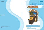
1-8. DELAY. Figure 1-3 shows a circuir arrangement of measurement of dela1' for a fixed delay line.
l-9. VELOCITY. Velocity of an object canbedetermined by measuring the time required for it to pass
from one transducer to another.
1-10. ROTATIONAL SPEED. High-speed rotarion can
be measured using a photomultiplier pickup to scan
a shaft which has been prepared with a:r alternately
reflective and non-reflective surface. Speed determinations for slow-speed shafts can be made in a
small fraction of a revolution from an optical pickup
scanning a pattern of closely spaced lines.
A. PULSES ON ISOLATED CABLES
I.II. UNPACKING AND INSPECTION.
B. PULSE DURATION
1-12. If the shipping-carton is damaged, ask tttat the
carrier's agent be present when theinstrumentis un-
packed. Inspect the instrument for damage (scratches,
dents, broken knobs, etc). If the instrument isdamaged or fails to meet specifications (Performance
Check, Pata4-14), notify the carrier and the nearest
Hewlett-Packard field office immediately (field offices.
are listed at the back of this manual). Retain the ship ping carton and the padding material for t}te carrierrs
inspection. The field office will nrrange for the repair or replacement of your instrument without waiting
for the claim against the carrier to be settled.
tl
l.----4{
1l
C. CONSECUTIVE PULSES
l+--l
I-I3.
tt
LD
-S- 563
Figure 1-2. Basic Start-Stop Signals
STORAGE AND RESHIP'NENT.
1-14. PACKAGING. To protect valuable electronic
equipment during storage or shipment always use the
best packaging methods availabie. Your HewlettPackard f ield off ice can provide packing material su ch
as that used in original factory packaging. Cor*ract
packaging companies in many cities can provide
dependable custom packaging on short notice. If
original material.s are unavailable, proceed as follows:
a. Cover panel with soft wrapping paper.
b. Wrap corrugated cardboard completely
around
instrument.
c. Pack instrument securely in strong corrugated
container (350 lb/square inch bursting test).
OELAY
START
d. Insert filler between wrapped instrument and
container to insure a snug fit on all surfaces of the
instrr:ment.
loSooo
@ trort
Figure 1-3. Delay Measurement
r-2
LO-S-562
1-15. ENVIRONMENT. Conditions duringstorageand
shipment should normally be limited as follows:
a. Maximum altitude 20,000 feet.
b. Minimum temperarure -40oF (-40oC).
c. Maximum temperature
167oF (75oc).
01290-3
-\
Model 5262A
Paragraphs
Section lI
2-I to 2-9
sEcrroN il
OPERATING INSTRUCTIONS
2.I.
INTRODUCTION.
2-2.
The Model 5262A has two independent channels
which determine the beginning and the end of a time
interval. Each channel has its
own TRIGGERSLOPE,
TRIGGER LEVEL, and MULTIPLIER controls. Figures 2-4 and 2-5 show procedures for making a time
interval measurement and a phase measurement. The
following paragraphs describe installation of the Model
5262A and the function of each control.
2-3. rNSTAttATtON.
2-4. Installing the Model 5262A is a simple matter.
Just slide it all the way into the plug-in compartment
of the Model 5243L and turn the knurled knobs on
either side of the compartment clockwise until tight.
Porver is supplied to the Model 5262A from the Model
5243L.
A. SIMPLE SQUARE
WAVE
2-5. CONTROtg.
2-6. FUNCTION SWITCH.
The function switch provides the operator with three modes of operation:
common, separate, and remote.
a. With the function switch in theCOMMONposition
START and STOP input connectors are connected together internally. Thus, if start and stop signals
come from the same source, set function switch to
CONiIMON and apply the signal to either input con-
nector. Adjust MULTIPLIER
and TRIGGER LEVEL
controls for each channel separately.
b. With the function switch intheREMOTEposition,
the time interval function becomes one of the remote
programming operations of the counter.
c. Wirh the function switch in the SEPARATE position the start signal must be applied toSTART input
connector and stop signal must be applied to STOP
input connector.
2-7. TRIGGER SLOPE. The TRIGGER SLOPE controls determine the slope a signal must have as it
B. PULSE ON
PEDESTAL
crosses the voltage level set by the MULTIPLIER
and TRIGGER LEVEL controls to start or stop a
measurement,
2-8. MULTIPLIER
AND TRIGGER LEVEL. These
controls work together to determine the voltage level
il
a signa\ must cross to start or stop a measurement.
For exai'rple with the TRIGGER LEVEL dial set at
+2 and the MULTIPLIER set at .3 the Model 5262A
will trigger as the input crosses the +0.6 volt level.
Suppose you have a pulse as shown in figure 2-1A'
there will be lirtle difference whether measurement
begins at Va or Vb. However, to measure interval
"y" of figure 2-18, you must be more careful. Set
TRIGGER LEVEL dial reading near0as a preliminary
01290-2
Lo-il-55r
Figure 2-1. Trigggr Level Settings
adjustment. Adjust the start and then the stop TRIGGER LEVEL controls. Watch for definite changes in
measured dme. Thus you know that start and stop
voltage levels are above the stepandthatthe indicated
time interval is actually "y".
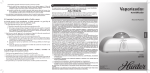
2.9. MULTIPLIER
AND TRIGGER LEVEL USING
OSCLLOSCOPE. This is an easier method because
you can see where the pulses are occurring with respect to the signal. Connectors at the rear of the
2-l
Section II
Model 5262A
Paragraph 2-9 cont'd
TRIGGER
LEVEL ON
(+) sLoPE
(__/_
bz
HYSTE RESIS
--t--LIM ITS
VOLTAGE STEP FROM REAR OF"@5243L
TRIGGER LEVEL
ON {-) SLOPE
|NPUT STGNAL
TO @SZAZa
Figure 2-2. Oscilloscope Display of Trigger Levels (front panel slope control set to neg.)
Model 5243L
ElectronicCounterprovideseparatevolt- d. Connect a cable from
age steps which occur at the same timeas the
pulses. Use the following procedure:
an oscillator to theSTART
input connector of the Model 5262A; frequency is not
important if it is a sine waveandthe range is between
trigger
a. Connect BNC-Io-BNC cable between START input connector on front panel of Model 5262A and EXT
AC S\TIC input of oscilloscope; use tee connector
UG-274A/U ar Model
e. Connect the STOP input connector ofthe@ 5262A
and the other channel of the oscilloscope.
5262A,.
f. Set VERTICAL
volts/cm.
b. Connect the START output connector at the rear
of the Model 5243L and one input channel of the oscil-
Set Model 5262A function switch to
SENSITIVITY controls
ro
.2
g. Set the VERTICAL PRESENTATION selector of
the oscilloscope to CHOPPED or ALTERNATE.
loscope.
c.
0 and 2 mc.
h. Display on the oscilloscope
that shown in figure 2-2.
COM.
will be similar to
INPUT CIRCUIT
@szeza
BLOCKING
CAPACITOR (c.)
--------l
SOURCE
I MPEDANCE
Rs
MULTTI PLIER
SETTTING
o.t
o.2
o.5
I
('id-a)
.237
.?37
355
.592
3
ro
r.30 .o39
30
roo
t8
.39
.r
SIGNAL
SOURCE
cs
-RFF
I
=
K= 4w2RC
L0-r-333
Figure 2-3. Remove DC Component from Sine Wave Input
2-2
01290-
l
Section
\4odel 5262A
lI
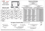
Figure 2-4
E
1. Turn SAMPLE RATE control to POWER OFF.
Plug in Model 5262A, turning knurled
2
desired oper-
Set SAMPLE RATE conlrol
ating rate.
9.
Set start channel SLOPE control to "+" if you
want measurement to start on positive slope'
knobs
cloclorise until tight.
J,
for
8,
Set SENSITIVITY switch to PLUG-IN.
Set to
sloPe.
Set FUNCTION switch to REMOTE OR TIME
"-" if you want tostartcount
on negative
INT.
Connect signai to START or STOP wirh selector
at com*o.t, to START and STOP at other posi-
I0. Adjust start MULTIPLIER
a.
COM
stop channel SLOPE control to "+" if you
want measurement to stop on positive-going
part of signal. Set to "'" if you want to stop
11. Set
if start and stop signals are from
same source.
b. REMOTE i.f the Model
5243L
is
count on negative slope.
being op-
erated frorn a remote control box.
c. SEP if start and stop signals are from
different sources'
1
LEVEL
desired voltage leve1.
tions of selector switch.
6. Set COM-REMOTE-SEP to:
and TRIGGER
controls to set measurement start point at
12.
and TRIGGER LEVEL
controls to set measurement stop points at desired voltage level.
Adjust stop MLLTIPLIER
Set TIME BASE switch to obtain greatest pos-
sible count, or to EXT if an external time unit
is to be used.
Figure
2-4.
13. Read
time interval units.
Opetating the Model 5262A
I
01290- r
_e,
Section II
Figure 2-5
Model 5262A
B1
I
)
Set FUNCTiON to REMOTE OR T]ME INT.
a.
Set SAMPLE RATE to position just
POWER OFF. (MAX SAMPLE RATE)
b.
Note counter reading wich MULTIPLIER
set to 0.1 position.
before
Note counter reading with MULTiPLIER
set to 0.2 positioa.
Set TIME BASE switch to obtain greatest pos-
sible count, or ro EXT if an External Freq is
counted to give an answer in degrees.
c.
4
Set COIv'I-REN'IOTE-SEP to SEP.
5.
Set start and stop TRIGGER SLOPE to same
polarity.
d. If reading in step b is iess than reading in
step a, add result of step c to reading of
step a and adjust TRIGGER LEVEL for
6.
e. If reading in step b is greater than reading
in step a, subtract result of step c from
reading of step a and adjust TRIGGER
start and stop TRIGGER LEVEL controls to 0 posirion.
LEVEL for result.
7, Set both
Note
8. Connect signals whose phase difference
9.
Set start TRIGGER LEVEL control for no dif-
ference in counter reading as start Mt 'I-TIPLIER is switched between the 0.1 and 0.2
positions. Procedure:
/.1i*L o urrr6.
r/^^
result.
Set both START and STOP MULTIPLIER concontrols to 0.1 position.
is tobe
measured to START and STOP inputs. (Note:
For specified accuracy, do notexceed*40vo1ts
peak times mulriplier setting.)
Subrract the smaller readingfromthelarger
The procedure may have to be repeated
to obtain exact zero crossing.
10.
Repeat step 9
for
stop TRIGGER LEVEL con-
tro1.
Il.Read phase difference in units selected
by
TIME BASE switch.
Figure 2-5. Procedure for Phase Measurement
01290-
1
Section II
Model 5262A
Paragraphs 2-10 ro 2-17
].IO. EII'UIINATING DC CONPONENT
\FROM SINE WAYE INPUT.
2-11. As the input circuits of the Model 5262A are dc
coupled it is sometimes easier to set theMULTIPLIER
and TRIGGER LEVEL controls whenanydc component
from the start and/or stop sine wave input signals is
eliminated with blocking capacitors. With the aid of
figure 2-3 you can select the proper value of blocking
capacitor for no readout error. For example' on the
.1 MULTIPLIER range, at 400 cps and with a source
impedance of 10,000 ohms the propervalueof blocking
capacitor is 25 pf.
2-12. However, if the right value of capacitor is not
available, use the following approximate formula to
determine what the error per channel in seconds will
be (for phase shifts less than 10o and signals less than
*40 volts peak times multiplier position):
Error in seconds
=
^'s -R)(2rt)' ffiL
-+::-:7.
-
Cs(R"+
Cs = Biocking capacitor
R. = Signal source imPedance
.\!-
x 10-7for 0. I and 0. 2 MULTIPLIER settings,
9 x 1o-7foro.3, 1.5 x 1o-6 for L,
3.3 x t0-6tor 3, 1 x lO-Sfor 10,
3 x lO-Sfor 30, 1 x t0-4for t00.
RC = 6
2-13. For example, on the .l MULTIPLIER range,
the use of a 10 pf blocking capacitor at 400 cps and
with a source impedance of 600 ohms resulas in an
error of 1.5 microseconds.
2-I4. PI{AsE
Tf,EASUREIIENT.
2-15. Phase measurement is a.special application of
time interval measurement. You measure the time
interval between like points on twosimilarwaveforms
and relate the reading to phase angle. The measurement is made between the points where the signals
cross 0 volt going in the same direction. The zerocrossing is the reference point for two reasons: first,
it is the easiest point to determine accurately on the
counter; and second, for sinewaves it is in the region
of maximum slope, allowing maximum resolution.
2-16. Phase difference is measured in time units if
one of the internal standard frequencies is counted.
The following formula converts time interval (t)
to phase (@) in degrees:
a=
360t
period of either signal
2.17. lf the two signals are not equal in amplitude,
use the larger for the period measurement. You can
measure phise directly in degrees if you apply theappropriate external frequency (360 x frequency of
signals whose phase youare measuring) tothe counters
in place of an internal standard frequency. However,
the external frequency cannot exceed the maximum
counting rate of the instrument. Procedure for phase
measurement is given in figure 2-5.
i;
i:
t;
;r1
T
tl,
il
,i
ti
u
6
0i290-
1
2-5
n
Section
IlI
Model 5262A
Figures 3-1 and 3-2
TRIGGER GENERATOR
START
I NPUT
START
AMPLIFIER
arre nunion
PULSE
AND
TRIGGER
TO
COUNTER
STOP
STOP
INPUT
PULSE
ATT EN UATOR
TO
COUNTER
LO-l-534
Figure
3-1. Overall Block Diagram of Model 5262A
I
EMITTER
FB
I
FOLLOWER
AMPLIFIER
EMITTER
FOLLOWER
I
LIMITER
LIM ITER
cRl,cR2
cR4, CR5
TRIGGER
LEVEL
coNrRoL
|
1
-,5v
DIODE SWITCH
START
I
TR IGGE
I
OR
R
STOP
crRcurT
PULSE
Q6,07
I
TO
COUNTER
I
I
SLOPE
Figure
3-0
3-2. Block Diagram ot @ 5262A-65A Trigger
LD-
U -
535
Generator Assembly
01290-l
Section lll
Paragraphs 3-1 to 3-6
Model 5262A
?
sEcTloN
lll
PRI.NCIPTES OF OPER,ATION
3-7 . The feedback circuit also includes the TRIGGER
3-r. TNTRODUCTION.
LEVEL control (Rl). Varying the dc bias of Q2 cong-2. The Model 5262A has two independentchannels,
trols the trigger level. This effectively shifts the
one for start pulse, the other for stop pulse' Each
channel includ-es an attenuator circuit followed by an
amplifier and Schmitt trigger. The block diagram'
tigure 3-1, shows the miin functionai sections and
si"gnal flow through the Model 5262A- Fqr each time
inierval measurement, the counter receiv€s two negative pulses; a start pulse and a stoppulse. The start
pulse opens a signai gate within the counter, which
ihen counts one of itsinternalfrequenciesoran external frequency until the stop pulse closes the signal
signal with rel-pect to rhehysteresis limits of the trigge? circuit theieby controlling the levels at which the
Model 5262A triggers.
+20v
gate.
3-3. TRIGGER GENERATOR.
3-4. GENERAL. The trigger generator forms the
puises which start or stop the time interval measurement. Signal flow initiating the output pulses can be
traced onlhe block diagram, figure 3-2. Paragraphs
3-5 through 3-12 describe the circuits included in the
s
trigger generator assembly in mcre detail.
3-5. AMPLITUDE LIMITER. Figure 3-3 shows the
circuit with input and output waveforms. Under normal operation diodes CRI and CR2 act as low resistanc" el"-.nts. However, positive peak overloading
o.
'ln
back-biases CR2 and negative peak overloading back-
biases CRl. Thus no signal level beyond the bias
limits reaches Ql.
3.6. FEEDBACK AMPLIFIER ANDTRIGGER LEVEL.
Figure 3-4 shows the circuit with the feedback path'
and Q3 form a feedback amplifier which provides
Qf
j uery siable
gain over a wide band of frequencies'
amplifyingthe
Q2 functions aJa differential amplifier
d-ifference between the input voltage appearing at its
base and the feedback voltage appearing at its emitter'
SIGNAL INPUT
LO-r-55?
Figure 3-4. Feedback Amplifier Circuit
SIGNAL OUTPUT
-r5v
FIXEO
.DC BIAS
,
CURRENTS
s
+13 V
LD
-x- t56
Figure 3-3. Amplitude Limiter Operation
01
290- I
3-1
Section III
Model 5262A
Paragraphs 3-8 to 3-12
3-8.
SCFIN4ITT TRIGGER. The trigger circuit is a
special form of switching circuit (bi-stable multivibrator) lvhich produces fast-risir-rg signals. Figure
3-5 shorrus the trigger circuit with input and output
waveforms. lf initially the input signal becomes more
positive, it will eventually reach a predetermined
level, point a in figure 3-5, at which the circuit
changes state; Q6 turns on and Q7 turns off. If the
input signal then goes negative, the emitter potential
decreases and Q7 base goes positive. When the input
reaches a second predetermined level, point b in figure 3-5, Q7 turns on and the circuit switches back to its
initial state. The output of the circuit is a current
step, either positive or negative depending upon the
slope of the input. (Transformer Tl i41,erts and
differentiates these current steps.)
3-9. HYSTERESIS LIMITS. The trigger circuit
switches at certain input signal levels. Norice that
the circuit does not switch unless the input signal
crosses both limits alternately. However, as shown
in figure 3'5, the trailing edge of Essl occurs at a
lower input volta$e level than that which causes the
leading edge. The reason for this is as follows: The
alternate off and on states of Q7 yields high and low
outputs, respectively. These off and on states of Q7
are caused by the on and off states of Q6. When Q6
is off, Q7 turns on and produces a low output. Current
flow through R26 due to the conduction of Q7 biases
the emitters of both Q6 and Q7 posidvelywith respect
to ground. This positive bias ar the emitter of Q6
necessitates a positive signal of certain amplitude on
the base of Q6 before Q6 will turn on and thereby turn
off Q7. When Q7 turns off, the current will then flow
through Q6 and R26. Since R23 is in the collector
circuit of Q6, the voltage drop acrossR26is less than
when Q7 was on. Consequently, the positive bias on
the emitters is now less than when Q6 was off.
3-10. In lhe meantime, the input signal has progressively (1) gone sufficiently positivetocauseQ6toturn
on, (2) increased to its maximum, and then (3) decreased from maximum to the point where its voltage
level is equal to that whichisnecessaryto turn Q6 on.
This would be the point where Q6mightbe expected to
turn off; but now its emitter is at a lower positive
potential, so Q6 now requires a lower positivevoltage
on its base to suppress the electron flow from its
emitrer and effectively turn it off. Therefore, the delay
in the turn-off of Q6 caused by its lower emitter bias
results in a slight increaseinthelengthof the squarewave output of Q7.
3-11. SHORT PULSES. An input signal
will cause
R?2
OUTPUT
HYSTERESIS
LIMITS
--t--OUTPUT
LO-M-5S
Figure 3-5. Trigger Circuit Operation
+
20v
+t3v
START OR
STOP SIGNAL
TO COUNTER
a
voltage step to appear at the collector of Q7, either
positive or negative depending upon the slope of the
input signal. Transformer T1 forms these voltage
steps into short pulses and inverts them.
3-12. TRIGGER SLOPE. The block diagram (figure
3-1) shows this control symbolically as a switch.
Diode switching places the useful, NEGATIVE start
or stop trigger pulse on the proper slope. Figure 3-6
shows the diode-switch circuit. Forward biasing
either CR6 (for negative slope) or CR7 (for positive
slope) provides trigger pulse for the desired slope.
The TRIGGER SLOPE control on the front panel
switches the bias from one diode to the other.
3-2
+ t3v
-r5v
L O
-r-
559
Figure 3-6. Diode Switch Circuit
01290-1
Model 5262A
Section IV
Paragraphs 4-I to 4-9
SECTION IY
,NAI NTENANCE
4-t. tNTRODUCTION.
4-2, This
section cont_ains troubleshooting information and a performance check for the Model 5262A.
No preventive maintenance is required for the Model
5262A, Time Inrerval Unit excepr an occasional visual
inspection.
4-3. TESr EOUtPmENt.
4-4. Test equipmenr required for troubleshooting,
for the performance check, and for adjustment of the
Model 5262A is lisred in table 4-I. Equipment of
equivalent characteristics may be substituted for
those lisreC.
b. Interchange trigger generator boards to isolate
trouble in a faulty channel to its board. The start and
stop channels of the Model 5262A are independent, and
trouble in one generally will not affect the other.
c. Refer to waveform chart, component location
drawing, and schematic diagrams (figures 4-l through
4-6) for guidance.
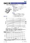
d. Apply a sine wave ro input of Model 5262A and
check points lisred with waveforms in figure 4-I.
4-7. The transistor is the component most likely to
be at fault. For example, a short between the collector and the emitter isolates the base from all following circuits and the applied signalwouldbeblocked
at the base. Another likely faulr is either a shorted
or
4-5. TROUBIESI|OOT|Nc.
4-6. A possible troubleshooting
procedure follows:
a. Remove the Model 5262A, from the Model 5243L
and reconnect it using the AC-16Y extender cable.
open diode.
4.E. SERYICING PRINTED CIRCUIT BOARDS.
4-9. To prevent damage to the board when replacing.
components, apply heat sparingly and work carefully.
The following replacement technique is recommended:
a. Remove defective component.
Table 4-1. Test Equipment
Type
Required
Specifications
Electronic Counter
@
AC Vacuum Tube
0 to 300 vac
voaet s24gL
VOLTMETER
Application
Recommended
Supply power for unit, visualindication ofpperation of unit
@
Voltage Measurements
@Model400D/H/L,
vtooet s24gL,
Electronic Counter
ACVacuum Tube
Voltmeter
DC Vacuum Tube
Voltmeter
0 to 300 vdc
Voltage and resistance
measurements
@ trrtodel
+tZa,
DC Vacuum Tube
Voltmeter
Oscilloscope
Dual Channel,
2mc
General troubl eshooting, checking
out waveforms
@
Model t50A Oscilloscope with
l52B Plug-In, or
Model t60B with
l62A,Plug-In, or
@ Modet tToA with
l62A Plug-In
@
Oscillator
0to2mc
Signal injection, check response of
@
Signal injection, check response of
@ trrtoOet
circuits in unit
f,
Square Wave
l0 cps to
Generator
100 kc
circuits in unit
lrlodet 6s0,t,
Test Oscillaror
Zf f e,
Square Wave
Generator
Test Cab]e
01290-3
Allows unit to be operated outside
of the counter
, (AC-t ny)
Extender cable
@ f OSOOI,
4-L
Section
I\i
Model 5262A
Paragraphs 4-10 to 4-15
b. Melt solder in holes; clean holes with roothpick
wooden splinter. Do not use a meral tool which
or
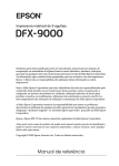
A.
may damage board.
BASE AND EMITTER OF QI AND Q2
+0.3v
c. Bend component leads to correct shape and insert in holes. Solder leads in place from opposite
side of board.
B. EMITTER
*3V-
d. If plating breaks on inside of holes (indicated by
lifting of conductor pad on opposite side of board)
OF Q4
press pad against board and solder component lead
to conductor on each side of board.
.
4-IO.
ADJUSTMENTS AFTER REPAIR.
4-11. As a general rule, unless a transistor or diode
is replaced, no adjustments will be necessary. Paragraphs 4-I2 and 4-13 indicate adjustments that are
necessary if transistors or diodes are replaced.
-2.5V
4-L2. ZERO-SET INPUT. lf repair is made to start
C. BASE OF 06
+o.6v-
channel, proceed as follows:
a. With the counter turned off, connectModel 5262A,
by means of the cable @ AC-16Y.
D. EMITTER
+o.4V-
b. Connect a cable from input of oscilloscope to
START input of Model 5262A. Set oscilloscope ver-
OF Q6 AND Q7
tical sensitivity to .05 v/cm.
c. On Model 5262A set both TRIGGER LEVEL
controls to 0, both MULTIPLIER controls to 100, and
_t.4v
the COM-REMOTE-SEP switch to SEP.
E. COLLECTOR
+2.0V
OF Q6
d. On the START channel circuit
€
board (@5262A-
65,{) adjust R6 for zero volts (plus orminus 10 millivolts) measured between center terminal of START
-
connector and chassis ground.
-
F. BASE
+t.ov-
e. Repeat steps a through d for STOP channel if
repair is made in the STOP channel board.
OF Q7
4-13. ATTENUATOR (MULTIPLIER).
If repair is
made to START channel proceed as follows:
a. Connect square-wave generator (use 75-ohm
-o.6v-
output of Model 211A')output to START input of Model
G. COLLECTOR OF Q7
5262A.
+2.6V
b. Set square wave generator for an output of 100 kc
at a 300 millivolt peak level (Model 21lA generates
only negative pulses).
H. INPUT OF CR6
c. Set start MULTIPLIER switch to .2, and adjusr
C9 on input MULTIPLIER switch so that same shape
square wave is seen at emittor of Q4 as when MULTIPLIER switch is in .1 position (square wave amplitude will decrease by two).
-2.6v
d. Repeat steps a through c for STOP channel if
repair is made in the STOP channel board.
w-M-r68
4.14. IN.CABINET
Figure 4-1. Waveforms Resulting from Input
Sine Wave at 1 Volt Peak-to-peak
4-2
PERFORTTANCE GHECX.
4-15. PRELIMINARY CHECK. Steps a through p
of the following procedure confirm that the feedback
01290-l
Section IV
Paragraphs 4-L6 to 4-I7
lr4odei 5262A
EHQBS@o @,,@@H @EBE
EEEEHB0 B@ffiEEEffiE8EEE
f
E ffi6EEEEgEH
05262 - A- 3
Figure 4-2. Component Location, Trigger Generator Assembly (A3' A4)
amplifier, the trigger circuit, the trigger level controls and the slope controls are working properly.
a. With the SAMPLE RATE control of the Model
5243L in the POWER OFF position plug the MoCel
5262A into the compartment. Now turn SAMPLE
RATE control slightly clockwise turning
it
on.
b. Set STORAGE switch at rear of Model 5243L
to off.
c. Set COM-REMOTE-SEP of Model 5262A to SEP.
d,
Set MULTIPLIEN tO .T.
e.
Set TRIGGER LEVEL to 0.
f
.
Set FUNCTION switch toREMOTE ORTIME INT.
g.
On MoCel 5243L set TIME BASE switch
h.
Set SIGNAL INPUT SWitCh tO PLUG IN.
to I ms.
i. Set start and stop SLOPE controls to "'".
j.--6Rotate start TRIGGER LEVEL control from +6
and back to +6. The Model 5243L will start
to
courting; the display will indicate the count and the
T
gate light
will glow.
k. Rotate stop TRIGGER LEVEL control from +6
The Model 5243L will stop
to -6 and back to +6.
counting indicated by gate light going off.
or290-2
m, Set start and stop SLOPE controls to "+".
n. Ro:ate start TRIGGER LEVEL control from -6
Model 5243L will start
to +6 and back to -6. The
counting.
p. Ro:ate stop TRIGGER LEVEL control from -6
-6. The Model 5243L will stop
ro +6 and back toward
counting.
4-16. MINIMTJM TIME INTERVAL. Thischeckshows
that the gate binary of theModel 5243L will respond to
pulses which are as close as one microsecond.
a. On Model 5243L set TIME BASE to . 1 pts and
FIINCTION to REMOTE or TIME INT.
b. On Model 5262A set start and stop TRIGGER
LEVEL controls to 0.
c. On Model 5262A set MULTIPLIERS to.1' TRIGGER SLOPES to opposite polarity, and COM-REMOTESET to COMMON.
d. Connect 500kc sinewave at 300mv rms to START
input.
e. Slowly adjusting TRIGGER LEVEL controls will
produce readout on Model 5243L
of I microsecold.
4-17. SENSITIVITY AND RESPONSE CHECK. Checks
are identical for START and STOP channels;
a. With the exception of step c follow procedure of
paragraph 4-15 stePs a through h.
4-3
Model 5262A
Section IV
Figure 4-3
Y}
Atct
Atc2
o',cg
o'*z
a2c5
A2C7
A2R7
A2R8
A2C9
A2R2
Figure
4-4
4-3.
Component Location Model 5262A (overall)
01290-
I
Section IV
Paragraph 4-18
Model 5262A
v?
-POSITIVE STEP
ON NEGATIVE
NEGATIVE STEP ON POSITIVE SLOPE
|NPUT STGNAL
TO @SZSZA
Figure 4-4. Voltage Step Coincident with Trigger Pulses
b. Connect START connector at the rear of the
Model 5243L to one input channel of the oscilloscope.
c. Connect a signal from an oscillator of 300millivolts to START connector of the Mo.del 5262A and the
oaher input channel of the oscilloscope.
d. Set VERTICAL PRESENTATION of the oscilloscope to CHOPPED.
e.
Sweep the range
of input frequencies from I
kc
ro above 2 mc at a level of 300 millivolts.
f. Over this range, voltage steps (coincident with
trigger pulses) similar to those shown in figure 4-4
will appear.
g. Repeat steps a through
f for STOP channel of
Mo,Jel 5262A.
4-18. ATTENUATOR (MULTIPLIER) AND TRIGGER
LEVEL CHECK.
a. Corurect negative output square-wave generator
(600 O output of Model 2114) to START input of the
Model 52624and to one of the charurels of the oscilloscope so as to shorr ttre input signal level.
01290 -2
b.
Set square wavegeneratortoapproximately 10kc
c.
Set
d.
Set start TRIGGER LEVEL to 0.
at about 300 millivolts peak.
start MULTIPLIER to 0.1 position.
e. Rotate start TRIGGER LEVEL control slowly
until gate light of Model 5243L goes on.
f. The TRIGGER LEVEL dial calibration should
indicate - 1.5 within plus or minus one division.
g. Change setting of MULTIPLIER control to
.2
and repeat step e.
h. Increase signal level of square wave generator
to 600 millivolts peak.
i. The TRIGGER LEVEL dial calibration should
indicate - 1.5 within plus or minus one divisio;r.
j. Repeat for all MULTIPLIER control settings.
Increase output of square wave generatorandincrease
MULTIPLIER steps, and nole that the attenuation in-
serted by the MULTIPLIER switch agrees with the
in square-wave level,
change
4-5
Section IV
Figure 4-5
A3 TRIGGER GENERATOR ASSEMBLY
------?+l-
AI INPUT SWITCH ASS€MBLY
*
STEP
FARTI
l-.i_-I-
----+-----ATTEN
JI
(FRONT PANEL)
PLUG-IN
ON SIG
t7
i ,1,'
tM-uLJrPLrERl
-l5V
r nr-----
E
r------q Jc--i
b
rm*r
I
lREMorA
L-----I
I
A4 TRIGGER GENERATOR
------f
A2 TNPUT SWITCH ASSEMBLY
I
sroPl
S
ASSEMBLY
'l+*
*
TEP
PLUG.I N
ON SIG
J2
'FRONT PANEL)
-l5Vra^v------
I
I
'' \
tniinr\
I
,/\/\/\
\____l___
I
\- srlnr
TIMF
REF E RENCE
DES16NATIONS
NOTES
I. UNLESS OTHERWISE
INOICATED:
RESISTANCE IT.I OHMS
2. AEBREVIATIONS:
0P.oECIMAL POINT
MU' MEASUREMENT UNIT
RC'REMOTE CONTROL
COPYRIGHT 1962 !Y HEWTET'.PACKATD COTAPANY
52621 /Trf€ rXT UNll a'n'62/7'2t
Figure
4-6
4-5. Overall Functional Diagram
=
TIME TRIG
TR
SraRT rlME
ISIGr
TRIGl
I
@
-('
tREMoril
zu
z
I
ic
'gH
ozo
FJ>
-ou
+oE
d>
<9
Zl
=E
@
,f>
lO
)E
IL
MELY
ENABLING
(+r70v)
STOP SIG
r
\rt
(REAR )\
\
+r3v
it
4s
ltt:l:
ll
,i,n
47
I
t
15
t7
23
\- Srqn , t,u,
r5v
I
_ T _l
,'-J-J
J5
OFF SIG
(.I5V)
45
/\/\,
43
,A
4l
t3
'.1
ENABLING
t/-DP
t+rzov)
ll
,31 /\
29
t'
+I7OV TO RC WHEN PLUG-IN OFF
+I7OV TO RC WHEN PLUG-IN OFF
Model 52624
A3
AI OR A2 INPUT SWITCH ASSEMBLY
PLUG-lN t4
ENABLING
(-I5V FROM
REFERENCE OESIGNATIONS WITHIN
'li";' ;tl+:l, \f
B:Slslll"el:
io
SIB)
*' *.''" *"
"8s,h'.tfi?
oii
(START) OR 44 (STOP) TRIGI
- l5V
!
FEEDBACK
DESIGNATIoN
truorcareo ^lo3*
AMPL
EMITTER
-t5v -l5v
START
OR
27.|K
(r/r0 w)
RI
/
ot
R2
IMULTTPLtERI
ft------------1
FOLLOWER
47
stBr
STOP
r
R4
853-ooo3
tooo
-
+20v
R9
o.oluF
03.
r65l
98.8K
ool
c9
8- 50
INPUT FROM
JI OR J2
E
" 20Krf--l€:--r
tl
^"3+ZZ
TO SIA
(coM-SEP
SWITCH ING)
?l
R3
g *-l-tt[!
R3
34.8K
0
I
/tow
R6
)
2000
,r rr'r/,l
o
+l3v
u
LI
IO UH
+ 20v
+20v
FROM
J3 (UO)
+ t3v
+ 13V
I
to
ll@
4.7UF
OV
fi
h
IM
e--un-l-O
Ice
o--4
15V
FROM
Rz+
3M
/v-#
Lcz
,l t30
-
-
T30
I
I
J3 (r3)
I
R6
vl!
c?
FROM
15V
J3 (r5)
I
I
"r*
loM
O-+aa-t'
Ic8
Io'
I
- r5V
FROM J3 (t5)
I
I
slc
tl
E
I
lsLoPA
- r5v
FROM
(15)
J3
REFERE NCE
DESIGNAT IONS
PRE F IX
AI
NOTES
I
UNLESS OTHERWISE INDICATED
RESISTANCE IN OHMS'
clilcrrance lN PIcoFARADS;
RESISTORS
I/4
WATT
OR A?
r-9
sl
R
PREF IX
A3 OR A4
cr-12
cR
r-10
Ll-3
or-7
Rr-34
TI
:rrrrrrrrrrrrrrrrg":Iy?-1lJ'"t"t"t".lt^Y"iT;li"tlT:,"o*t^*t
lsra
uz l3ftFl
STEP
l
ATTEN
lr
l-l
I
ltrluurtPutrn
I
I
ri-t5V
ii --^A --i
I '-- t r---l
i| - --, br.# ai
-tSv
,-------
i
I
I
I
I
01290-4
TRIGGER GENERATOR ASSEMBLY (5262A-65A)
A3 (START) OR 44(STOP}
-15v
o.5v
R7
2000
AMPL
EMITTER
-l5v -tsv
R4
FOLLOWER
r
853-OOO3
-r5v
FEEDBACK
R9
EMITTER
----
+20v
FOLLOWER
Q4
R?7
?N2044
rooo
Rro
4700
94.8K
toK
EMITTER
OV
FOLLOWER
-l5v
o5
2N2048
z-TRIG ----r.
ov
ddo
t
c9
!19
cR4 CR5
- t9to oot6 00t6
r9 to
Rr5
350
c6
47
+
l3v
R20
4300
+t3v
R2l
rooo
IEST POINT
+
l3v
REFERENCE DESIGNATIONS WITHIN TRIGGER
P - ASSEMBLY ARE ABBREVIATEDi
)MPLETE DESIGNATION, AOD ASSY
TO FO
DESIGI\.*-JN 43 OR A4 AS PREFIX
TO
INDICATEO DESIGNATION
PULSE TO COUNTER INPUT
ON START CHANNEL
NC ON
STOP CHANNEL
A3 OR A4
TRIGGER GENERATOR ASSEMBLY
At OR
A2
-t5v
PLUG - IN
ON SIG
t4
INPUT SwlrcH ASSEMBLY PLUG-iil
Jr
lffiFil
J2 lF6Fl
ENASLTNG I
STEP
ATTEN
lMrrLrrPLrER I
I
START OR
STOP TIME
TRIG
PULSE TO COUNTER
INPUT ON START CHAN.
NC ON STOP CHANNEL.
START OR STOP SIG
sta
J5(I)
t
Section IV
Figure 4-6
\-
GENERATOR ASSEMBLY (5262A-65A)
PLUG
- IN ON
stG ro J3 (4r)
oR J3 (40)
R33
2000
START OR STOP
TIME TRIG TO
J5 il,46) OR J3(47)
EMITTER
FOLLOWER
05
2N2048
--TRIG -.'
START OR STOP
SIG TO
J3 (2r) OR J3 (22)
cR3
r9ro-0016
Rr7
rooo
cR4
t9to0016
CRs
t9to00t6
R20
4300
+t3v
TEST POINT
+ l3V
j
:EFERENCE DESIGNATI0NS wlTHlN TRIGGER
ENEF ' ASSEMBLY ARE ABBREVIATED;
)MPLETE DESIGNATION, AOD ASSY
O FOI
IESIGNLJ'N A3
OR
A4 AS PREFIX
TO
VDICATED DESIGNATION
PULSE TO COUNTER INPUT
ON START CHANNEL
NC ON
J3(I)
STOP CHANNEL
A3 OR 44
TRIGGER GENERATOR ASSEMBLY
-t5v l4
'LUG-
PLUG - IN
ON sIG
START OR
STOP TIME
TRIG
PULSE TO COUNTER
INPUT ON START CHAN.
NC ON STOP CHANNEL.
START OR STOP SIG
05?6?-
D
-
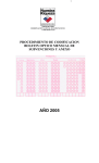
|
\Figure 4-6. Switch and Trigger Generator
4-7
/4-8
Section V
Model 5262A'
Paragraphs 5-1 to 5-6
SECTION Y
REPTACEABTE PAR.TS
5-t.
5-2. This section contains
Miscellaneous parts are listed at the end of
Table 5-1.
5-3.
TNTRODUCTION.
information for ordering
replacement parts. Tables 5-1 thru 5-3 list parts in
alpha-numerical order of their reference designations
and lndicate the description and @ stock number of
eaeh part, together with any applicable notes. Table
5-4 lists'pa"I" in alpha-numeiicat order of their @
stock number and provides the following information
on each part,
a. Description of the part (see list of abbreviations
5-4. ORDERING INFORMATIdN.
5-5. To obtain replacement parts, address order or
inquiry to your local Hewlett-Packard Fieid Office
(see Iist at rear of this manual for addresses).
Identify parts by their Hewlett-Packard stoek numbers.
5-6. To obtain a part that is
not listed' inelude:
a. Instrument model number.
below).
b. Typical manufacturer of the part in a five-digit
list of manufacturers in Table 5-5-
b. Instrument serial. number.
c.
c. Description of the part.
code; see
Manufacfurer's part number.
d. Total quantity used in the instrument
(TQ column).
d. Frnction and location of the part.
RXFERENCE DESIGNATORS
assembly
B=
motor
capacitor
CP
CR
coupling
diode
delay line
device signaling (IamP)
DL
DS
E
= misc electronic Part
F=fuseP=
FL
=filter
I
=jack
K
= relay
L=inductorS=
M=meterT=
mechanical part
MP
plug
a
R
=
=
= terminal board
= test polnt
= vacuum tube, neon
w
= cabie
= socket
= crystal
v
transistor
resistor
thermistor
RT
TB
TP
x
switch
bulb, photocell' etc.
transformer
Y
N/c
normal.Iy closed
NE
neon
RMO = rack mount only
RMS : root-mean-square
NI PL
nickel plate
normally open
negative positive zero
(zero temperature
ABBREI'IATIONS
A
A.F.C
AMPL
B. F. O.
BE
CU
amplifier
GRD
beat Irequency oscilLator
beryliium copper
H
binder
BP
bandpass
bras s
head
BWO
backward wave oscillator
ccw
counter-clockwise
CER
ceramic
cMo
cabinet mour* only
COEF
coefllcient
coM
CW
common
composition
connector
cadmium plate
cathode-ray tube
clockwise
DEPC
deposited carbon
DR
drive
ELECT
electrolytic
ENCAP
EXT
encapsulated
F
FH
farads
FXD
fixed
COMP
CONN
CP
CRT
i
GL
BH
BRS
FIL II
01194-10
01290-4
GE
amperes
automatic f requencY control
external
flat
germanium
glass
ground(ed)
head
N/o
NPO
HG
HR
= henries
= hexagonal
= rnercury
= tour(s)
IF
IMPG
INCD
INCL
INS
INT
= intermediate freq
= impregnated
= incandescent
= include(s)
= insulation(ed)
= internal
NSR
HEX
K
= kilo=1000
OBD
order by descripuon
OH
oval head
ox
PC
peat
printed circuit
Dico.farads
PF
LOG
LPF
= Iogarithmic tape!
= iow Pass filter
PH BRz
M
= milli=10^-3
MEG = meg=10b
METFLM = metal film
MFR = manufacturer
MINAT = miniature
N
=
nano (to-91
oxide
P=
=
Unear taper
LK WASH = lock washer
coefficient)
not recommended for
field replacement
not separately
replaceable
NRFR
LIN
MOM = momentary
MTG = mounting
MY
= "mYlar"
head
fillister
=
=
=
PHL
PIV
P/o
POLY
=
io-12 faraas
=
phosphor bronze
PNUips
peak inverse voltage
part oi
polystyrene
PORC
porcelain
POS
PT
position(s)
trrctentiometer
peak-to-peak
point
RECT
RF
rectifier
radio frequencY
RH
round head
POT
PP
S-B =
SCR =
SE =
SECT =
slow-blow
screw
selenium
section(s)
SEMICON = semiconductor
SI
SIL
SL
SPL
SST
SR
STL
TA
TD
TGL
TI
TOL
=
=
=
=
=
=
=
=
=
=
=
=
TRIM =
TWT =
U
silicon
silver
slide
special
stainless steel
split ring
steel
tanta.lum
time delay
toggle
titanium
tolerance
trimmer
traveling wave tube
= micro=10-6
VAR = variable
VDCW = dc working volts
w/
W
WW
W/O
= with
= watts
= wirewound
= without
5-l
Section V
Table 5-1
Model 5262A
Table
uircuit
Reference
5-1.
Components Located on Chassls (No Prefix)
@ Stock No.
Description
A.1, A2
52624-L9A
A3, A4
5262A-65,4.
Switch, attenuator
A""y., trigger generator
C1
0150-0093
C: txd, cer, 0.01
JL, J2
1250-0083
1251-0099
Connector: female, type UG-l094/V
Corurector: male, 50 pin
2100-0076
R var, comp, 75 ohms +L|Vo
S1
3100-0338
Srvitch,
xA1, XA2
xA3, XA4
1251-0135
Not assigned
Connecton 15 pin, (for pc)
J3
Rl.,
R2
rot:
Note
Y'*
I
plf +80Vo -20V0, 100 vdcw
2 sect, 3 pos
MISCELLANEOUS
0370
0370
0370
0370
-00 76
-0077
-0102
-0110
KNOb: TRIGGER LEVEL
Knob: FIJNCTION
Knob: TRIGGER SLOPE
KNOb: MIILTIPLIER
skirt: TRIGGER LEVEL
skirt: MULTIPLIER
52624-40A
5262A-408
Knob,
Knob,
05262-0001
05262-2002
Board Mounting Bracket
Panel - Front
r*
# See introduction to this section
5-2
0L290-2
Model 52624
Table 5-2.
Section V
Table 5-2 through Table 5-3
prefixed A1 or A2)
(designations
5262A-19A
Attenuator Switch Assy,
0160-01-82
0160-0181
0160-0178
0150-0042
C: fud, mica,
fud, mica,
C: .fud,
47 pf. *570, 500 vdcw
30 pf +5V0, 500 vdcw
mica, 27 Pf. +57o, 300 vdew
TiO2, 4,7 Pf *5V0, 500 vdcw
C:
0150-0029
C: fxd,
C: fud, TiO2r
0140-0203
0160-0183
0140-0149
0130-0008
C: fxd, mica, 30 Pf'+570, 500 vdcw
C: fud, mica, 130 Pf +5V0, 300 vdcw
C: fud, mica, 410 Pf *\Vot 300 vdcw
C: var, cer' 8-50 Pf
0683-1135
0683-2035
0686-9135
0683-3045
0683-1055
1 Pf *l|Vo, 500 vdcw
R fud, comp, llK
R: fud,
R fud,
R fud,
R: fud,
ohms *580, L/ 4 W
comp, 2OKohms +|Vo, t/4W
91K ohms *580, L/ 2 W
comp, 300K ohms +5V0, L/4W
comP, 1M +5/e, L/4W
comp, 3M +5%, L/ 4 W
comp, 10M +570, L/ 4 w
comp, 680 ohms +5V0, L/ 2 W
0683-3055
0683-1065
0686-6815
a.
Optimum value selected at
factory'
average
value shown.
Ta,ble
b-3. Trigger
cL
c2
c3
C4
c5
C6
C7
C8
c9
C10 thru C12
Generator Assy, 5262A-65A (designations prefixed A3 or A4)
0160-0127
0180-0100
0160-0127
0140-0202
0150-0093
C: fud, cer, L 1.tf. *20V0, 25 vdcw
C: fxd, tantalum elect, 4.7 1tf +t\Vo, 35 vdcw
C: fud, cer, L ptf. *20V0, 25 vdcw
C: fud, mlca, 15 Pf +5%, 500 vdcw
C: fud, cer, 0.01 Pf +8AVo -20V0, 100 vdcw
0140-0204
0140-0151
0140-0204
0140-0145
0150-0093
C: fud, mica, 47 Pf. +570, 500 vdcw
C: fud, mica, 820 Pf +2V0, 300 vdcw
C: fud, mica, 47 Pf. +570, 500 vdcw
C: fud, cer, 22 *57o, 500 vdcw
C: fxd, cer, 0.01 prf +80Va '20V0, 100 vdcw
1t'f.
# See introduction to this section
01290-2
5-3
Model 52624
Table
5-3.
A (designations prefixed A3
Trigger Generator AssY' 5262A-65
or
Section V
Table 5-3
A4) (Contrd)
Circuit
Reierence
L/4
R: fud, comP' 220 ohms +58o,
L/4 W
R: fud, comP' 10K ohms *5V0,
L/4W
R: fxd, comP' 16K ohms +58o,
L/4 W
+5E0,
R: fud, comP' Z.IK ohms*580, L/ 4 W
R: fud, comP, 24K ohms
W
0683-2215
0683-1035
0683-1635
0683-2725
0683-2435
0683-2725
0683-2435
0683-2025
0683-3915
9130-001-8
Z.TK ohms +58o, L/4 W
24K ohms +,Va, L/4 W
L/4 W
fud, comP' 2K ohms +5V0,
L/4 W
fud, comP' 890 ohms +580,
R: fud, comP,
R: fud, comP'
R
R:
Transformer, pulse: 10 Pt'h
# See introduction to
0L290-1
this section
5-5
Section V
Table 5-4
Model 5262A
Table
5-4.
Replaceable Parts
Mfr.
Mfr. Part
Iirob: FIINCTION
I{nob: TRIGGEN SLOPE
03?0-01-10
ltuob: MULTIPLIER
0526i-0001 Board Mounting Bracket
05262-2002 Panel, Front
28480
28480
28480
28480
28480
28480
0370-0076
0370-0077
0370-0102
0370-0110
05262-0001
05262-2002
52624-L9A
52624-404
52621'-408
52624-654
Switch, attenuator
Knob, skirt: TRIGGER LEVEL
Knob, skirt: MULTIPLIER
Assy, trigger generator
28480
28480
28480
28480
52624-L9A
52624-40A
2
52624-40E-
2
5262A-65A
2
0130-0008
0140-0145
0140-0149
0r-40-0151
0L40-0202
C: var, cer, 8-50 pf
C: fud, mica, 22 pf. *570, 500 vdcw
C: fud, mica, 470 pf +5V0,300 vdcw
C: fud, mica, 820 pf *2V0, 300 vdcw
C: fud, rniea, 15 pf *570, 500 vdcw
72982
72L36
72L36
72L36
72L36
557 -023U2P034R
DM15C22OJ
2
0140-0204
0150-0029
0150-0042
0150-0093
0160 -0127
C: fud, mica, 47 pf. +570, 500 vdcw
C: fud, TiO2, 1 pf +L|Vo, 500 vdcw
C: ftd, TiO2, 4.7 pf *5V0, 500 vdcw
C: fod, cer, 0.01 plf+80V0-20Vo,100vdcw
C: fud, cer, L pf. +2070, 25 vdcw
72L36
82L42
82L42
0160-o178
0160 -0181
0160-0182
0160-0183
0180-0100
C: fi<d, mica, 27 pf. *570, 300 vdcw
C: fud, mica, 30 pf +5V0, 300 vdcw
C: fud, mica, 47 pf. *570, 300 vdew
C: fud, mica, 130 pf. +5V0, 300 vdcw
C: fud, ta eleet, 4.7 1tf *tlvo, 35 vdcw
72L36
72L36
72L36
72L36
56289
DM15E270J300V
DM15E300J300V
DMl5E470J300V
4
DMl5E13lJ300V
2
150D475X9035B2
2
0683-1025
0683-1035
0683-1055
0683-1065
0683-1135
R fud,
R ftd,
R fxd,
1K ohms +570, L/4W
10K ohms +5Y0, L/4W
1M ohm +5V0, L/4W
10M ohms +5Y0, L/4W
l1K ohms *580, t/ 4W
01121
OLL2L
01121
cB1025
c81035
c81055
c81065
c81135
6
0683-1615
0683-1635
0683-1805
0683-2025
0683-2035
R: ftd, comp, 160 ohms *5V0, L/ 4W
R: fud, eomp, 16K ohms *5V0, L/ 4W
R; fxd, comp, 18 ohms *5V0, L/4W
OLL2L
c81615
c81635
c81805
c82025
c82035
2
Description
@stocx No.
0370-0076
#
I(aob: TRIGGER LEVEL
03 70 -00 ?7
0370 -01'02.
R:
R:
comp,
comp,
comp,
ftd, comp,
fud, comp,
R ftd,
R ftd,
eomp, 2K ohms +5V0, L/ 4W
comp, 20K ohms +5Y0, L/ 4W
#See introduction to
5-6
9l_418
56289
OLLZL
01121
01121
01121
01r_21
01121
No.
w*
rQ
2
1
2
2
,
l_
2
DM15F47lJ
2
2
DM15F821G
DM15C150J500V
2
I
DMl5E47OJ
T'ype JM, obd#
Type JM, obd#
TA, obd#
5C13
6
2
2
9
4
2
2
2
2
2
2
2
2
4
4
this section
01290 -3
Section V
Table 5- 4
Model 52624
Table
5-4.
DescriPtion
Replaceable Parts (Cont?d)
Mfr. Part
#
fxd, comp,
fod, comp'
fud, comp,
R fud, compo
R: fud, comp,
220 ohms +5q0, L/ 4 w
24K ohms $qo, L/ 4 w
z.1K ohms +5V0, L/4w
S0of ohms +5V0, L/ 4 W
3M.+570, L/ 4 W
01121
01121
01121
01121
01121
cB22r5
c82435
c82725
c83045
c83055
fud, comp,
R fxd, comP,
R fud, comp,
R fud, eomp,
R: fud, comp,
830 ohms +5V0, L/ 4 W
390 ohms *5V0, L/ 4 W
4.3K ohms +5V0, L/4 w
4? ohms *5V0, t/ 4 W
4.7K ohms *5V0, L/4W
01121
cB3315
c83915
c84325
c84705
cB4725
0683-5605
0683-5615
0683-6215
0683-6815
683-9135
R fxd, comp,
R fud, c omP,
R: fud, comp,
R ftd, comP'
R: fud, comp,
56 ohms +5V0, L/ 4 W
560 ohms *57o, t/ 4 W
620 ohms +5q0, L/ 4 W
680 ohms *5V0, L/ 4 W
91K ohms *|Vo, t/ 4 w
01121
01121
01121
0686-6815
0686-9135
0757 -0L22
0757 -0L23
0757 -0L24
R fud, comP, 680 ohms +5V0, L/2 W
R fud, comp, 91K ohms *5V0, L/2W
683-22L5
0683-2435
0683-27 25
0683-3045
83-3055
R:
R:
R:
0683-3315
0683-3915
683-4325
0683-4705
0683-4725
R:
OLL2L
01121
01121
01121
01121
OLL2L
OLL2L
01121
R: fi<d, mfgl, 27.IK ohms *LVo, L/LO W 75042
75042
R fud, mfgl, 34.8K ohms +t%o, L/Lo
75042
R: fxd, mfgl, 39.2K ohms +lqo, L/LO
fud, mfgl, 98.8K ohms tLEo, L/LA
0757 -0L25
No.
obd#
1251-0099
1251-0135
02660
57-10500
sD-615UR,
Special
1850-0091
1853-0003
1854-0005
Transistor: 2N2048
Transistor: Si, PNP
Traasistor: 2N708
872L6
?3293
07 263
2N2048
1901-0025
1901-0033
1910-0016
Diode, Si
Diode, Si: 1N459A
Diode, Ge
07933
07910
98925
RD1526
19459A
CGDlOOS
2100-0076
2100-0355
R:
01121
80294
JA1NO56S750UA
Type 220, obd#
#See introduction to
0t290-2
this section
4
2
uc-1094/U
R:
2
E86815
E89135
obd#
obd#
obd#
9t737
var, comp, ?5 ohms +LIVo
var, comp, 2K ohms +?|Vo
4
2
75042
95354
2
cB5605
c85615
c86215
c86815
cB9135
Connector: female, tYPe UG-1094/U
Connector: male, 50 Pin
Connector: 15 Pin, (for Pc)
t_250-0083
2
HAg079
2N708
2
2
4
2
2
2
2
2
Section V
Tabie 5-4
Model 5262A
Table
Description
0)Stock No.
3100 -0338
Switch,
9130 -0018
9140-0146
rot:
5-4.
Replaceable Parts (Contrd)
#
2 sect, 3 pos
Mfr. Part
No.
obd#
1
{lransformer, pulse: 10 ph
01961
PE4502
2
Inductor: fxd,
99800
L025-44
6
10 prh
-'6*
IQ
71590
#See introduction to
5-8
Mfr.
this section
0L290-2
Appendix
Model 5262A
APPENDD(
This manual appties directly to the 5262A Time Interval Units having
prefix 516. This manual with the following changes also
""riJr"*Uer
;;il" to SZOZ4 Time Interval Units having serial prefix numbers 450,
229, and2t1.
prefixes other
To adapt this manuaf to instruments with serial number
changes:
following
the
make
51-6
than
Instrument Serial Prefix
Change No.
1
450
Lr2
229,211
CHANGE 1:
Tables 5-1, 5-4,
CHANGE 2:
Fisure 4-6, Tables 5-3, 5-4,
belete eSCnf o t& part No. 1910-0016.
Change: 05262-0001 to 5262.4'-14'
05262-2002 to 5262A-2A
r$
!
01290 -2
II
f,
I
S
..
.':::!
r!*:'.
li
-:l :-il::''r':
IA-1