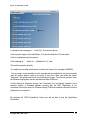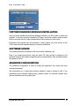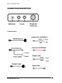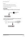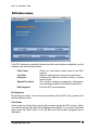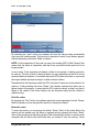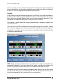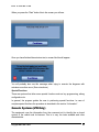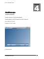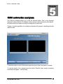
1
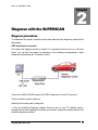
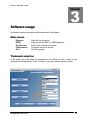
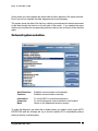
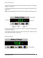
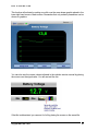
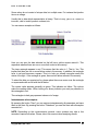
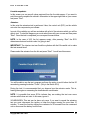
SUPERSCAN II
Always a step ahead.
Operations Manual
DEC Automotive ®
Pedro Lozano 4453
Capital Federal • C 1417 EEY
Argentina
Telephone +54 11 4567 1188 / 3994 • Fax +54 11 4639 8643
http://www.decautomotive.net/
Version 6.0.0
January 1st 2008
[email protected]
Copyright: All material included in this manual is public domain and can be found in the services manual for every
automobile brands. Part of it is also an interpretation by the author and specific details of the DEC products. Please
contact us via mail or email if you have any questions . Thank you.
DEC
AUTOMOTIVE
Table of Contents
PROLOGUE ........................................................................................................................................................ 5
SYSTEM REQUIREMENTS ............................................................................................................................. 5
RECOMMENDED READINGS ........................................................................................................................ 5
WARRANTY ....................................................................................................................................................... 6
CUSTOMER SERVICE ..................................................................................................................................... 6
SOFTWARE INSTALLATION......................................................................................................................... 6
SOFTWARE LOADING .................................................................................................................................... 9
SOFTWARE REMOVAL................................................................................................................................... 9
SOFTWARE CONFIGURATION..................................................................................................................... 9
FURTHER DIAGNOSIS MODULES INSTALLATION.............................................................................. 12
SOFTWARE UPDATE ..................................................................................................................................... 12
ADVANCED CONFIGURATION................................................................................................................... 12
CONNECTIONS DESCRIPTION................................................................................................................... 13
CONNECTION WIRES .......................................................................................................................................... 13
DIAGNOSE PROCEDURES ........................................................................................................................... 14
DEC SUPERSCAN II CONNECTION:.................................................................................................................... 14
FIRST TESTS....................................................................................................................................................... 15
MAIN SCREEN................................................................................................................................................. 16
TRADEMARK SELECTION .......................................................................................................................... 16
ON BOARD SYSTEM SELECTION. ............................................................................................................. 17
LOCATION OF DIAGNOSE SOCKETS ....................................................................................................... 20
ECU DETECTION............................................................................................................................................ 20
DETECTION OF THE DEVICE WHICH IS CONNECTED TO THE USB OR SERIAL RS-232 PORT................................. 21
DETECTION OF THE VEHICLE ECU. ................................................................................................................... 21
CONNECTING.................................................................................................................................................. 22
CONNECTION TO THE DIAGNOSE SOCKET WITH INCORPORATED POWER SUPPLY. ............................................ 22
CONNECTION TO THE DIAGNOSE SOCKET WITHOUT INCORPORATED POWER SUPPLY. .................................... 22
(CABLE TO VEHICLE’S BATTERY MUST BE USED) ............................................................................................... 22
ECU DATA SCREEN. ...................................................................................................................................... 23
END DIAGNOSIS ................................................................................................................................................ 23
Copyright DEC 1995 - 2010
3
DEC
AUTOMOTIVE
FAULT CODES ................................................................................................................................................... 23
Print the codes............................................................................................................................................... 24
Erase the codes ............................................................................................................................................. 24
LIVE DATA ........................................................................................................................................................ 25
Instantaneous values capture. ....................................................................................................................... 28
LIVE DATA SNAPSHOTS ..................................................................................................................................... 29
ACTUATORS ...................................................................................................................................................... 29
SPECIAL FUNCTIONS ......................................................................................................................................... 30
GENERIC SYSTEMS (VW ONLY) ................................................................................................................ 30
OSCILLOSCOPE.............................................................................................................................................. 32
TECHNICAL SPECIFICATIONS. ............................................................................................................................ 32
CAN NETWORKS ANALYZER..................................................................................................................... 34
Copyright DEC 1995 - 2010
4
DEC
AUTOMOTIVE
1
Chapter
Introduction
PROLOGUE
Thank you for purchasing a DEC Superscan!
Our company is proud of developing the second generation of the well known
Superscan. In this new model you will find more specific features for each On board
Electronic System in particular.
It is our wish that this diagnose tool fulfils your expectations. Please note that your
system can always be updated by downloading the latest patches from our web site:
www.decautomotive.net.
System requirements
Before your start installing, you must bear in mind the minimum requirements for this
software. Basic configuration recommended is as follows:
IBM AT Compatible Pentium II 400 MHz or later
512 MB RAM memory
Video SVGA 800 x 600 of 65535 colors (16-bit)
50 MB free space in hard disk.
1 USB or serial port (dedicated).
Windows XP or Vista.
RECOMMENDED READINGS
It is highly recommended to read and use others books related to the automotive
electronic diagnose in order to complement the ideas we provide with this manual. It is
also important to refer to the service manual for each automobile trademark.
Copyright DEC 1995 - 2010
5
DEC
AUTOMOTIVE
WARRANTY
The warranty covering interface failures is unlimited. DEC develops and manufactures all
its products under strict quality standards, with excellent final results.
CUSTOMER SERVICE
Our aim is to collaborate with our customers to provide better usage and appliaction of
our products.
In case of difficulties that cannot be solved with the information provided in this manual,
we offer a 24 hour fax line and two assistance telephone lines available for questions, or
malfunctioning issues from 12 pm until 8 pm (GMT).
It is very important that you register your equipment. You can register on our web site:
www.decautomotive.net or by sending your registration card via fax or mail. Your
registration allows us to keep you well informed about our new updates and our
products.
DEC Technical support.
FAX: (011) 4639 - 8643
Telephones: (011) 4567 – 1188 / 3994
E mail: [email protected]
SOFTWARE INSTALLATION
The software installation is launched from the Windows Desktop (close all other
programs in use) Follow these instructions:
1. Turn your PC on.
2. Insert the dec AutoScan Manager CD and wait a few seconds.
Every CD ROM software contains an AUTORUN program which starts the software
installation automatically.
In some rare occasions this AUTORUN program can be disabled. If this happens, you
can run the program manually by entering the Start menu. Select ‘My Computer’,
CDROM Unit, and run the file named “superscan2005”¨.
3. To continue the installation process you must select the installation wizard language
and press OK in the wizard welcome screen.
Copyright DEC 1995 - 2010
6
DEC
AUTOMOTIVE
4. The next step is to complete the fields (Name, Repair shop, Address, Telephone and
Fax), with the corresponding information. This data will appear in the headings of the
report printouts and will be requested when installing the software. Of course you are
able to change the information you entered from the configuration screen from the
AutoScan Manager if required. (All fields must be completed with at least one character
to be able to continue with the installation)
5. In the welcome screen the version you are installing is shown. Press “Continue” to go
to the next step.
6. Press the “Accept” button in the same screen which shows the license contract. This
step is necessary to continue with the installation and confirms that you agree the terms
and conditions of the contract.
7. The installer will prompt you to specify the modules to install, selecting them in the
check box at the left hand side, followed by its activation key.
This activation code enables the operation of each module independently. If you omit to
select some of them at this moment, you can do this at the end of installation by pressing
the “Configuration” key, entering the “Advanced configuration” option, filling in the code in
and pressing the “Update” button.
Copyright DEC 1995 - 2010
7
DEC
AUTOMOTIVE
8. At the end of the installation process, the wizard will ask you if you want to install the
Adobe Acrobat in your PC. This software is necessary to read the information screens
for the automobile trademark. If it is already installed in your machine press NO,
otherwise press YES.
Copyright DEC 1995 - 2010
8
DEC
AUTOMOTIVE
After completing these steps correctly, the AutoScan Manager will be successfully
installed and an icon will be created in your Desk screen. After this, run the AutoScan
and make the corresponding configuration for the user’s data as well as the designated
COM to the DEC SuperScan. (You will find explanation to this as follows).
NOTE: Do not remove the installation CD until you have completed the configuration of
the communications ports. The drivers for the USB port are inside the CD.
SOFTWARE LOADING
Make a double click on the AutoScan Manager icon on your Windows Desktop screen.
This Icon is automatically generated during the installation process.
or
Press the Start menu button and choose Programs from the menu.
Click on the icon of the AutoScan Manager inside the DEC Automotive Tools menu.
SOFTWARE REMOVAL
Should you want to remove the software you must follow these steps:
Quit the program and choose the option “Add/Remove Programs” from the “Control
Panel”.
In the list, select AutoScan and then press “Remove”.
Warning: To erase correctly the AutoScan Manager does not erase the files from your
hard disk, you must execute the removal procedure.
SOFTWARE CONFIGURATION
After running the software, choose “Configure” in the main screen.
The configuration of the Communications Port is essential for the functioning of the
equipment. In this version we have incorporated an auto detection routine for the
SuperScan. If you want to configure your computer automatically you should follow these
steps.
USB Hub.
Plug in the interface cable. You do not need 12 volt power supply. Windows detects it
automatically and will request a Driver’s selection.
Windows XP: This operating system detects automatically the device and will ask for the
driver.
Copyright DEC 1995 - 2010
9
DEC
AUTOMOTIVE
Windows 9x: After connecting the SuperScan, go to “Control Panel”, “System” and then
“Devices”. Select the corresponding in the USB list and then press “Properties” and then
“Change Controller”.
Select the driver you find inside the folder ¨USB Drivers ¨ in the installation CD or let
Windows select it for you automatically.
RS-232 Port.
Detecting the diagnose Device
Connect your DEC equipment to the free serial port on your PC.
Connect the DEC equipment to a 12 Volt source using the OBD-II wire or with the wire
with alligator clips (remember that the DEC equipment must always be powered, to be
able to communicate with your PC)
If the DEC equipment is properly connected to a 12 Volt source, the red and green lights
on the front should be on, and the blue light should blink. Otherwise, unplug and plug in
the equipment again. If the failure persists, please contact DEC customer service.
Enter the configuration screen and press the “AutoDetection” button.
The software will automatically open all communication ports and scan among them the
one which the SuperScan is connected to.
When you get the message “SuperScan found <serial #>” associated to a port, the
equipment was successfully detected and it is ready to use.
Copyright DEC 1995 - 2010
10
DEC
AUTOMOTIVE
If, otherwise the message is: “…Free Port”, this could be due to:
Lack of power supply to the SuperScan. (You should check the 12 Volts cable).
Lack of or defective serial connection.
If the message is: “ ....failure in…..(Whatever it is )”, then:
The serial connection is faulty.
You might have another serial device connected to the port, for example a MODEM.
You can select a port manually, but be sure that the port selected is not being currently
used by another device, such as a mouse. If that is so, when you select the option
“Diagnose”, the software will inform you that the port is busy. To solve this problem, enter
the software configuration screen and select another COM port.
If after starting a diagnose through the Command Unit and having selected some
injection system; a message appears showing that the DEC SuperScan is not
connected, this can be due to a free and existing COM port selected, other than that the
equipment is connected to.
By pressing the “INFO SuperScan” button you will be able to see the SuperScan
information.
Copyright DEC 1995 - 2010
11
DEC
AUTOMOTIVE
FURTHER DIAGNOSIS MODULES INSTALLATION
Once you have installed the AutoScan Manager software, you will be able to install new
modules. To do this, insert the installation CD again, and in the module’s window check
the box and write the Key Code corresponding to the module you want to add.
Remember that together with the purchase of each module you must receive a Key
Code, which must be available when you make the installation.
SOFTWARE UPDATE
The update procedure is identical to the new modules installation one.
Note: If you install several times using the same CD, there will be no damage to the
software, because the installer recognizes versions automatically. Only updated modules
will replace old ones.
ADVANCED CONFIGURATION
The advanced configuration is used to modify the registration key codes and some
software parameters.
We recommend you to keep these options unaltered, unless a change is vital. If you
experience some software malfunctioning, please contact our technical support team
and we will advise how it may be solved.
Copyright DEC 1995 - 2010
12
DEC
AUTOMOTIVE
CONNECTIONS DESCRIPTION
Connection wires
Copyright DEC 1995 - 2010
13
DEC
AUTOMOTIVE
2
Chapter
Diagnose with the SUPERSCAN
Diagnose procedures
To understand the system operation quickly and make an easy diagnosis, please follow
these steps:
DEC SuperScan II connection:
Find where the diagnose socket is located. It is generally inside the car or in the fuse
board. You can find the location by searching in the software corresponding to each
trademark and pressing the “Connector” button.
Connect the USB or RS-232 output of the DEC Superscan II to the PC input port.
Turn the vehicle’s ignition switch on.
Selecting On board system to diagnose
1. Run the AutoScan Manager software from the icon in your PC desktop screen.
Remember that after installing the software you should configure the system options and
install the diagnose modules.
Copyright DEC 1995 - 2010
14
DEC
AUTOMOTIVE
2. Choose the option “Diagnose” in the main screen.
3. Choose the vehicle trademark you want to diagnose and press “Continue”.
In this screen you can complete the vehicle data which can then be printed if you wish.
Even if you do not complete this data, diagnose can be done anyway.
4. Choose the on board system you need to diagnose. For example, the electronic fuel
injection system.
If you are not sure about the type of system installed in the vehicle, search for this
information in the car’s manual, in the label on the ECU top cover or ask by telephoning
DEC Customer Service. If you choose a system in error, this causes no malfunction in
the vehicle or in the interface, but the equipment will not be able to connect to the ECU.
First tests
Once you have selected the system and established the communication with the ECU
you will see the ECU data screen, in which, appears the name of the system, the
software version according to the engine and vehicle model, ECU part number and
other specific data depending on the car’s trademark.
We recommend you read the rest of this manual carefully before continuing with the
diagnose procedure. We suggest the following::
Make a reading of the failure codes.
Make a quick reading of the live data watching the individual values and check them by
placing the mouse pointer over the value that has been measured.
Make an actuators test.
IMPORTANT: remember to read the rest of this manual in order to learn about the
diagnose data and details, as well as the particular cases.
Copyright DEC 1995 - 2010
15
DEC
AUTOMOTIVE
3
Chapter
Software usage
All software functions and options will be explained in this chapter.
Main screen
Diagnose
EOBD
Oscilloscope
Configuration
Quit
Start with the diagnose.
Start the generic OBD II / EOBD diagnose.
Enter in the oscilloscope screen.
Configure the user’s options.
Quit the program.
Trademark selection
In this screen you must select the trademark of the vehicle you are or about to get
connected to the SuperScan. Press “Continue” to go to the system selection screen.
Copyright DEC 1995 - 2010
16
DEC
AUTOMOTIVE
In this screen you can complete the vehicle data so that it appears in the report printouts.
Even if you do not complete this data, diagnose can be done anyway.
The system saves the data of the last four vehicles you analyzed and creates an access
to this data through the buttons on the left side of the screen. If you analyze the same
vehicle you can press the corresponding button so that you do not have to enter the data
again.
On board system selection.
Auto Detection
Continue
Establish communication automatically.
Establish communication manually.
Information
Connector
Back
To see the ECU connection explanation.
To see the diagnose output connection and location
Return to the trademark selection screen.
To make the diagnosis, just select the on board system you need to verify, press AUTO
DETECTION and the software will try to find the vehicle’s ECU automatically without
having to specify a certain system.
Copyright DEC 1995 - 2010
17
DEC
AUTOMOTIVE
If the system cannot make the connection with the command unit you will see a window
like this:
First of all, verify the screen information, it could simply be a connection failure, such as
not having connected the diagnose cable to the vehicle output.
After checking this, you can retry the procedure by pressing “Retry”. Another option is to
press “Analyze” and you will see this screen:
Copyright DEC 1995 - 2010
18
DEC
AUTOMOTIVE
This screen has two voltage indicators which allow you to check if the diagnose signal
appearing in the connector is correct.
If there is any problem in the vehicle diagnose input, which prevents it from connecting to
the system, the program will provide you with a possible solution to this problem. For
instance, check if the cable has short-circuited.
It is possible that the auto detection is not successful even though the software is
connected to the command unit. In this case the software will inform you about the
problem and you must select the system manually and press the “Continue” button. This
process forces a connection. For this reason you must be sure you have made the right
system selection.
Copyright DEC 1995 - 2010
19
DEC
AUTOMOTIVE
NOTE: If you have selected a system which does not correspond to the vehicle, the
information you see might be incorrect.
IMPORTANT: Under these circumstances, it is important that you press the button
“Generate Report”. Doing this, the vehicle data will be stored and will help us in
developing the software in the future.
Location of diagnose sockets
This screen shows where the diagnose sockets might be, shape of the connectors used
by the vehicle and how to connect the SuperScan to it. Check in the manual, in the
section referring to each car, the different ways to make the connection and the adaptors
that might be necessary.
It may be possible that the connector is not placed as specified, depending on to each
vehicle’s variations.
It should be indicated in the user’s or service manual. If you can not find this information
about the diagnosis socket, please do not hesitate to contact us.
ECU detection
Once you reach this screen, the software will conduct two operations.
Copyright DEC 1995 - 2010
20
DEC
AUTOMOTIVE
Detection of the device which is connected to the USB or serial RS-232 port
The device can be connected either to the diagnose input only or also to the car’s
battery. (See following: types of connection) It must also be connected to the USB hub or
to a serial RS-232 port of the PC, and must be correctly selected in the communications
port in the software configuration screen.
If the software cannot connect to the DEC SuperScan, please verify that the USB or RS232 serial connection as well as the 12 volt power supply to the equipment are correctly
made. If the power supply is 12 volts, a red light will turn on (Device on). The green light
on indicates that the equipment is ready to be used (Device Ready).
Detection of the vehicle ECU.
If the vehicle’s ECU is detected, you will see the data corresponding to it in your screen.
Otherwise, the software will tell you that no connection was made. The causes of this
failure can be:
The vehicle’s ignition is off.
The diagnose cable is not properly connected.
You are trying to detect a system which has not been included in the software.
Turn the ignition off an then on again.
Copyright DEC 1995 - 2010
21
DEC
AUTOMOTIVE
Solutions:
Check the connection cables you are currently using.
Check the connection that shows the connection screen.
Contact DEC customer’s service.
Connecting
Connection to the diagnose socket WITH incorporated power supply.
Connection to the diagnose socket WITHOUT incorporated power supply.
(cable to vehicle’s battery must be used)
Copyright DEC 1995 - 2010
22
DEC
AUTOMOTIVE
ECU data screen.
If the ECU has been successfully detected and the communication established, you will
be able to use the following functions.
Fault Codes
Live Data
Actuators
Special Functions
End diagnosis
Allows you read failure codes stored in the ECU
memory.
Begins reading several component parameters.
Activates the different actuators during a certain
period of time.
This function enables programming, initializations
and encodings related to the different calculators.
Ends the ECU communication.
End Diagnosis
By pressing this option, you end the communication with the ECU and go back to the
system selection screen.
Fault Codes
In this screen you will be able to see the failure codes stored in the ECU memory. When
you enter this screen the codes will be displayed automatically. If you need to read them
again, press the “Read” button. In the list there the code number will appear and its
description.
Copyright DEC 1995 - 2010
23
DEC
AUTOMOTIVE
By activating the “Auto” button the software will read the failure codes automatically
every two and a half seconds. This function is important to watch if new failures appear,
without depressing the button “Read” to refresh.
NOTE: If in the description of the code you see a text reading [INT] or [Not Present], this
means that the failure is intermittent, and that it has occurred at some point but is not
longer present.
In most cases, if the command unit detects a failure in the system, it makes a record in
its memory. The time it takes to detect a failure can vary depending on the ECU and its
system analysis procedures. It is possible that some ECUs take some time or even need
the engine started and kept running for a while to detect a failure.
Remember that the Superscan reads the ECU only when it has some codes stored in its
memory. If after pressing the button “Read”, the software indicates that there are no
failure codes in the memory, it means that the ECU could not detect, by itself, any kind of
failure in the vehicle. Even when failures can be observed easily and the vehicle is
malfunctioning.
Print the codes
By pressing the “Print” button, the software prints the codes appearing in the list. Please,
select the printer you are using and the amount of copies you require.
Erase the codes
To erase the codes, you must press the button “Erase”. Most of the codes filed in the
memory will be erased once the failure is repaired and by pressing the button “Erase”
other codes remain even after being erased. This is because the sensor or actuator must
recognize that the failure has been fixed after you erased it from the memory. Some
Copyright DEC 1995 - 2010
24
DEC
AUTOMOTIVE
sensors are easy to check in their functioning. For example, the engine temperature
sensor. Alternatively,, the idle regime regulation sensor needs more time to be detected
by the ECU. This only depends on the different command units.
Live data
In this screen you will see different groups,each of four blocks, the values calculated by
the ECU and the different signals together with their corresponding titles. We refer to
these values as calculated because they are not values measured physically by the
SuperScan, but data processed by the ECU and stored in its memory.
For example, in several cases the cooling fluid temperature is indicated in degrees, but
not in volts or ohms.
This is due to how the ECU measures the signal value coming from the sensor, making
the conversions programmed in its memory, and then it delivers the value in degrees. It
is important to know this, since in some cases you must take into account the real value
as well as the calculated one.
NOTE: Please remember that the function “Live data” can be used only if the ECU was
successfully detected. If you have selected the system manually and mistaken the
system, it may happen that the information is not reliable and the data not correct.
In the screen you will find two buttons to change the value group. In the top and middle
you will see the value group you are working with, and how many are left. The amount of
value blocks depends on the on board system you are analyzing.
Copyright DEC 1995 - 2010
25
DEC
AUTOMOTIVE
Under each button appears the function key to execute the same function. For example,
Previous = F1, Next = F2.
The Status light indicates when the values in the screen change. This light will turn from
green to red.
NOTE: The refresh speed varies with every ECU due to different communication speed .
We can see in every indicator the title, unit of measure, current value and maximum and
minimum values reached.
The maximum and minimum values will refresh every time you change the screen
group. Double click over them to insert zero.
Graphic chart function
Copyright DEC 1995 - 2010
26
DEC
AUTOMOTIVE
This function will activate by making one click over the wave shape graphic placed in the
lower right hand corner of each screen. Remember that only numeric parameters can be
shown on graphics.
You can also see the correct values indicated in the vehicles service manual by placing
the mouse over the signal value. You will see text like this:
If the title is abbreviated, you can see it in full by placing the mouse on the same title.
Copyright DEC 1995 - 2010
27
DEC
AUTOMOTIVE
Some values do not consist of unique data, but multiple ones. For instance the injection
time or a voltage.
Usually this is data which representation is binary. That is to say, yes or no, correct or
incorrect, valid or invalid, present or absent, etc.
You can see an example as follows.
Here you can see, the data selected on the left has a yellow square around it. This
represents whether there are one or more fault codes in the memory.
The inner rectangle appears in red. This means that the value is 1. That is, Yes. This
implies that there are one or more failure codes in the memory. In addition, the rectangle
turns to red and becomes a square. This is to help you visually recognize easily the
status of the light. If the rectangle is green; there are no failure records in the memory.
To select the data you require text for, please place the mouse cursor over the rectangle
or square and make a click with the left button.
The correct value appears generally as green. This indicates no failure. The colours
make the reading easier. When looking at a binary indicator you must pay attention to
the rectangles in red.
The rectangles in dark grey represent values out of usage.
Instantaneous values capture.
By pressing the button “Save” you can capture instantaneously all parameters and save
them in the chart. By pressing the button “Datasheet" you see the chart with all samples
recorded in it.
NOTE: Depending on the communication protocol, some systems may take a few
seconds to capture all values. Please, take it into account when analyzing results.
Copyright DEC 1995 - 2010
28
DEC
AUTOMOTIVE
Live data snapshots
In this screen you can see all values captured from the live data screen. If you want to
print this screen,complete the vehicle’s information in the upper right field on your screen
and press “Print”.
Actuators
In this point the actuators test is performed. Here, the control unit (ECU) on the vehicle
acts over the components you indicate.
In most of the vehicles you will see a window with a list of the actuators which you will be
able to test. To start the diagnose you must select them with your mouse and then press
“Start”. Once the test is completed you can repeat it several times.
NOTE: in the case of VW, the list appears empty, after pressing “Start” the ECU
determines what and in which order it is going to test.
IMPORTANT: The injectors test can flood the cylinders with fuel. Be careful not to make
this test several times.
Please select the actuator from the list and press “Start”. You will see this screen.
You will be able to see the test progress and have the option to end it before the first 30
seconds by pressing the button “Finish”. (Only in the Bosch ECU)
During the test it is recommended that you observe how the actuator works. This is,
hearing the engine or measuring the terminals with a multimeter.
NOTE: It is possible that some ECUs indicate they are making the test over some
actuator which does not exist. In this case, ignore it.
VOLKSWAGEN: This test can be done only once. If you want to repeat the actuators
test you must disconnect the ignition or keep the engine running for more than 10
minutes. To reset the function unplug the connector for 20 seconds from the command
unit or disconnect the battery from the car.
Copyright DEC 1995 - 2010
29
DEC
AUTOMOTIVE
When you press the “Start” button this is the screen you will see.
Once you have finished the actuators test, a screen like this will appear:
You will probably also see this message when trying to execute the diagnose with
actuators more than once. (See note above)
Special Functions
There are systems that allow some special functions such as key programming, airbag
configuration etc.
In general, the program guides the user in performing special functions. In case of
complex special functions the procedure is described in the section “Information”.
Generic Systems (VW Only)
The equipment uses the information from the command unit to identify the on board
system of the vehicle and its features. This is to say, the tests available and other
characteristics.
Copyright DEC 1995 - 2010
30
DEC
AUTOMOTIVE
When the software does not recognize the system, it can identify the data sent by the
ECU but not the system type. In these cases the software enables the user to fulfill some
functions such as failure codes reading or erasing them, make an actuators test and on
some occasions, live data reading.
By choosing the generic mode, everything works as normal but the live data parameters
will not have titles. In order to identify signals you can use the vehicle’s service manual
searching in the section diagnose the signals description, for each data block.
Copyright DEC 1995 - 2010
31
DEC
AUTOMOTIVE
4
Chapter
Oscilloscope
Technical specifications.
Number of channels: 2 simultaneous channels.
Sampling frequency: 250.000 samples per second, (maximum).
Input voltage: 0 to 50 volts.
Resolution: 15 mV (12 bites).
Channel selection
Copyright DEC 1995 - 2010
32
DEC
AUTOMOTIVE
Scale selection:
Base timing selection:
Trigger selection:
Measure cursors usage:
Copyright DEC 1995 - 2010
33
DEC
AUTOMOTIVE
5
Chapter
CAN networks analyzer.
The CAN bus analyzer allows you to test the network cables. This is very important
because in newer vehicles, the different control units are interconnected by this network.
At physical level, this means to verify the voltage level in each wire.
Thanks to special algorithms, the software automates this process, simplifying the fault
detection task.
To start the analysis of the CAN network press the button “Start” and wait for a minute.
To see the results of the analysis press the button “Results” and a screen containing
information will appear – see following.
Copyright DEC 1995 - 2010
34
DEC
AUTOMOTIVE
The results shown here are:
BUS CAN type:
High Speed: 250kbps -1Mbps
Fault Tolerant: 50 kbps – 125 kbps
Single Wire: 33.3 kbps
BUS status:
Active: there are packet transmissions over the wires
Inactive: there are no packet transmissions over the wires.
Voltage analysis:
The value can be in or out of range. If it’s outside range, verify the reading in not close to
zero (short circuit to gorund), or close to battery voltaje (short circuit to positive).
Copyright DEC 1995 - 2010
35