1
Section:
METERING/DOSING PUMP
Page: 1 of 5
Date: July 2009
SERVICE MANUAL
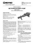
METERING/DOSING PUMP
BARE SHAFT
A4015A, A4050A, A4100A, AND A4190A, A2400A, and A4400A MODELS
DESIGN FEATURES
Suction Housing: Stainless steel
Bearing Housing: Cast iron
Pump Rotor: Chrome plated, 300 series stainless steel
Pump Stator: Nitrile, EPDM, Fluoroelastomer
Shaft: 300 series stainless steel
Bearings: Prelubricated, fully sealed ball bearings
Seal: Single or double mechanical seals, packing
Flexible Joint: Prelubricated and sealed
INSTALLATION
Mounting. Provide the proper alignment between the pump
and drive by mounting both to a common flat base. Pump may
be mounted in any position. When mounting vertically, it is
necessary to keep bearings above seals to prevent possible
seal leakage into bearings. Loosen screws on body support
and stator support to rotate pump to desired position.
Pre-Wetting. Prior to connecting pump, wet pump elements
and mechanical seal or packing by adding fluid to be pumped
into suction port. Turn shaft over several times in a clockwise
direction when viewed from the shaft end to work fluid into
pump elements.
Piping. Piping to pump should be self-supporting to avoid
excessive strain on pump housings. The suction port is 1-1/2"
NPT and the discharge port is 1-1/4" NPT. Use pipe “dope” or
tape to facilitate disassembly and to provide seal.
Drive. On belt driven units, adjust belt tension to point of nonslip. Do not overtighten.
On direct drive units, coupling components should be aligned
and spaced at least 1/16" apart.
– Pump rotation must be clockwise when facing shaft. –
Check direction of rotation before startup.
– Maximum speed is 1750 rpm.
OPERATION
Self-Priming. With wetted pumping elements, the mechanical
seal model pump is capable of 15 feet of suction lift when
operating at 1750 rpm with pipe size equal to port size.
DO NOT RUN DRY. Unit depends on liquid pumped for
lubrication. For proper lubrication, flow rate should be at least
10% of rated capacity.
Storage. Always drain pump for extended storage periods
using pipe plug in suction housing.
Pressure Limits. See Table 1 for maximum discharge
pressure of each model.
Table 1
Models
4015
4050
4100
4190
2400
4400
Max. Pressure 300 PSI, 20 bar
Max. Pressure 300 PSI, 20 bar
Max. Pressure 300 PSI, 20 bar
Max. Pressure 300 PSI, 20 bar
Max. Pressure 175 PSI, 12 bar
Max. Pressure 300 PSI, 20 bar
Temperature Limits. Unit is capable for service at 10°F to
210°F with nitrile, and to 260°F with EPDM, and 350°F with
fluoroelastomer. Note: an undersize rotor may be required for
elevated temperature applications.
TROUBLESHOOTING
WARNING: Before making adjustments, disconnect power
source and thoroughly bleed pressure from
system. Failure to do so could result in
electric shock or serious bodily harm.
Failure to Pump.
1. Belt or coupling slip: Adjust belt tension or tighten set screw
on coupling.
2. Wrong rotation: Rotation must be clockwise when facing
shaft.
3. Excessive suction lift, vacuum or obstruction in suction
piping.
4. Flexible joint broken; possible excessive pressure: Replace
joint, check pressure at discharge port.
Will Not Start.
1. Insufficient horsepower: Check motor starting torque for
minimum model starting torque given on performance
curves.
2. Low voltage: Check power supply.
Page 2
Noisy Operation.
PUMP DISASSEMBLY
1. Starved suction: Check fluid supply, length of suction line, and
obstructions in pipe.
2. Bearings worn: Replace parts; check alignment, belt tension,
pressure at discharge port.
3. Broken flexible joint: Replace part; check pressure at discharge
port.
4. Insufficient mounting: Mount to firm base. Vibration-induced
noise can be reduced by using mount pads and hose on
suction and discharge ports.
WARNING: Before disassembling pump, disconnect power
source and thoroughly bleed pressure from
system. Failure to do so could result in electric
shock or serious bodily harm.
Pump Overloads.
4. Remove stator support clamp screw and remove top half of
stator support (38).
1. Excessive discharge pressure: Check discharge pressure for
maximum rating given in Table 1. Check for obstruction in
discharge pipe.
2. Excessive temperature.
3. Belt or coupling slip: Check pressure at discharge port.
4. Loose bond in stator: High temperature and caustics will cause
bond between rubber and tube to fail. Replace stator. Check
fluid temperature and pressure at discharge port.
5. Fluid viscosity too high: See chart below for recommended
maximum RPM.
Viscosity CP
Limit RPM
1-1,000
1750
1,000-2,500
1200
2,500-5,000
600
5,000-10,000
300
10,000-20,000
175
20,000-50,000
80
Based on 60% min. volumetric efficiency. See PEC449 or consult
Moyno representative for exact values.
6. Motor connected incorrectly: Motor wired for 230 VAC,
connected to 115 VAC service.
Poor Performance.
1. Low pressure; worn stator: Replace stator: Check for
excessive abrasive material in fluid. Check for run dry
condition.
Mechanical Seal Leakage.
1. Leakage at startup: If leakage is slight, allow pump to run
several hours to let faces run in.
2. Persistent seal leakage: Faces may be cracked from freezing
or thermal shock. Replace seal.
Pump Will Not Prime.
1. Air leak on suction side: Check pipe connections. Suction lift
over 15 ft. will cause seal faces to open.
2. Defective mechanical seal: Inspect and repair as necessary.
MAINTENANCE
General. These pumps have been designed for a minimum of
maintenance. The pump is one of the easiest to work on in that
the main elements are very accessible and require few tools to
disassemble.
Bearing Lubrication. The prelubricated, fully sealed bearings do
not require additional lubrication.
1. Disconnect power source.
2. Remove suction and discharge piping.
3. Discharge coupling (9) may be removed from stator (21) by
unscrewing in a counter-clockwise direction (RH thread).
5. Stator (21) may be removed from suction housing (2) by
unscrewing in a counter-clockwise direction (RH thread). Use
strap wrench on stator to avoid crushing with a pipe wrench.
Pull stator (21) from rotor (22). To assist removal of stator, hold
drive shaft (26) from turning and turn stator clockwise when
facing suction housing after disengaging thread.
6. Remove screws (112) holding suction housing (2) to bearing
housing (1) or adapter (74). Remove suction housing and
suction housing gasket (83). Gaskets on cast iron models only.
Remove O-Ring (270) on other models.
7. The rotor (22) and flexible joint (24) may be removed using the
following procedure (do not bend joint more than 15 degrees).
a. Remove rotor (22) from flexible joint (24) by using a punch
to remove rotor shaft pin (46). Support joint while removing
pin.
b. Remove joint (24) from shaft (26) by using a punch to
remove shaft pin (46).
8. Single Mechanical Seal Models. Carefully slide mechanical
seal (69) off shaft (26). Carefully pry seal out of bearing
housing (1), or seal housing (3). Remove seal housing if pump
is a stainless model.
Double Mechanical Seal Models. Carefully slide seal housing
(71) from the drive shaft. Remove rotational part of mechanical
seal from the shaft. Carefully remove seal gland (73) from
adapter. Remove stationary seal faces if required.
If any parts of mechanical seal are worn out or broken, the
complete assembly should be replaced. Seal components are
matched parts and are not interchangeable.
Packing Models. Slide stuffing box assembly from the shaft.
Remove packing gland halves and replace packing.
9. The bearings (29) and shaft (26) assembly can be removed
from bearing housing (1) after snap ring (66) has been
removed. To remove the shaft assembly, lightly tap the shaft at
the flexible joint connection end using a block of wood to
protect the shaft. The bearings may be pressed off the shaft.
PUMP ASSEMBLY
1. Press bearings (29) on shaft (26), and locate slinger ring (77)
on the shaft near the radial bearing.
NOTE: When replacing bearings, always press on the inner race
when assembling to shaft, and on the outer race when
pressing bearings into the housings.
2. Press shaft assembly into bearing housing (1) securing with
snap ring (66).
3. On stainless steel models install seal housing (3) in bearing
housing with O-Ring (270) installed in the O-Ring groove.
On packing models install stuffing box assembly (stuffing box,
packing, and packing gland) on shaft with O-ring (270) installed
in the O-ring groove.
Page 3
4. Install mechanical seal (69) or (70) using the following procedure:
a. Clean and oil sealing faces using a clean light oil (not grease).
CAUTION: Do not use oil on EPDM parts. Substitute glycerin or
soap and water.
b. Oil the outer surface of the seal seat, and push the assembly
into the seal bore in the bearing housing (1), or seal gland and
housing, seating it firmly and squarely. On double seal models
install seal gland on shaft.
c. After cleaning and oiling shaft, slide the seal body along the
shaft until it meets the seal seat.
d. Install seal spring and spring retainer or seal housing with Orings (72 and 270) on shaft.
5. The flexible joint (24) and rotor (22) may be installed using the
following procedure (do not bend joint more than 15 degrees):
a. Pin flexible joint (24) to shaft (26) using the shaft pin (46).
b. Pin rotor (22) to joint using rotor pin (46). Support joint while
installing pin.
6. Secure suction housing gasket (83) (cast iron pumps only) and
suction housing (2) to bearing housing (1) using lock washers
(215) and screws (112).
266
733
NOTE: Apply pipe “dope” on all pipe threads before assembly.
9. Lubricate rotor (22) surface to assist installation of stator
(21). Slide stator on rotor, and screw into suction housing
(2) by turning clockwise (RH threads). An additional assist
in installing stator is to lock the shaft from turning and
rotate the stator counter-clockwise while pushing towards
suction housing.
10. Secure clamp assembly (40) to the stator support (38) and
the support retainer (39) using the clamp assembly (40)
screw.
11. Proceed as in installation instructions.
WARNING: Replace belt or coupling guards before
reconnecting power.
When ordering parts, please specify pump model number,
pump serial numbr, part number, part description and quantity.
Packing Models
Double Seal Models
744
7. Slide stator support retainer (39) on stator (21).
8. Screw coupling (9) on stator (21) in a clockwise direction
(RH thread).
711
722
Note: Item 83 is used on cast iron only.
700
2700
Page 4
BARE SHAFT MODELS PARTS LIST
Item
Type
1
2
3
9
21
22
24
26
29
37
38
39
40
46
66
69
69
70
71
72
73
74
75
76
77
78
79
83
112
215
261
270
300
CD
SS
CD/SS
SS
See Table
See Table
Q,R,B,F
SS
SS
SS
SS
SS
SS
SS
SS
Q,R,B,F
Q,R,B,F
Q,R,B,F
SS
Q,R,B,F
SS
SS
SS
SS
SS
SS
SS
Q,R,B,F
SS
SS
SS
Q,R,B,F
SS
Description
Bearing Housing
Suction Housing
Seal Housing
Discharge Coupling
Stator
Rotor
Flexible Joint
Drive Shaft
Bearing
Body Support
Stator Support
Stator Support Retainer
Clamp Assembly
Rotor/Shaft Pin
Snap Ring
Mech Seal (Cbn vs Cer)
Mech Seal (AR)
Double Mechanical Seal
Seal Housing, Double
O-Ring
Seal Gland, Double
Adapter
Packing Set
Suffing Box
Slinger Ring
Packing Gland Half
Packing Gland Stud
Housing Gasket
Screw
Lock Washer
Drain Plug
O-Ring
Nameplate
Qty
A4015, A4050, A4100, A4190,
A2400, A4400
1
1
1
1
1
1
1
1
2
1
1
1
1
2
1
1
1
1
1
1
1
1
1
1
1
2
2
1
4
4
1
1
1
3308813000
3403932007
3403930007
3205342020
See Stator Table
See Rotor Table
3308811005
3303577002
6300503031
3403947001
3403945001
3201733000
3204277000 and 3201734000
3204069001
3205162000
3206501000
3206503000
3208652002
3403986015
3207902128
3403985015
3501688004
3403396002
3403934007
3206382000
3403933007
3208591000
3203028005
6191520141
6230010401
6100420030
3207905134
3208597000
Page 5
Element
4015
4050
4100
4190
2400
4400
Q (Nitrile)
3403923104
3202145013
3403924104
3403925104
4252489102
4252489104
Stator Material
B (EPDM)
3403923304
3203676013
3403925304
3403925304
4252489302
4252489304
Element
4015
4050
4100
4190
2400
4400
F (Fluoro)
3403923504
3303719013
3403924504
3240392504
425489502
4252489504
Rotor
300 Series
SS and CD
3403927015
4252492015
3403928015
3403929015
4252524015
4252491015
For further information, call:
Inside U.S.A. - 800-845-1310 or 800-325-1331
Outside U.S.A. - 937-327-3553
© 2009 by Moyno, Inc.
® Moyno is a registered trademark of Moyno, Inc.
Moyno, Inc. is part of the Fluid Management Group, of Robbins & Myers, Inc.
Printed in U.S.A.