1
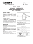
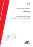
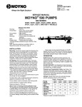
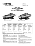
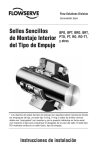
Section:
MOYNO® 500 PUMPS
Page: 1 of 4
Date: March 2002
SERVICE MANUAL
MOYNO® 500 PUMPS
SANITARY/HYGIENIC MOTORIZED
331, 332, 333 AND 344 MODELS
SANITARY MODELS
These pumps include housings polished to a #4 finish
both inside and out. The Durametallic FRO mechanical seal
has carbon/ceramic faces. The elastomers meet the FDA
requirement for food contact. These pumps meet 3A requirements. The universal joint may be dismantled for cleaning.
HYGIENIC MODELS
These pumps provide the quick disassembly features
of the sanitary version for easy cleaning. The housings
are 316 stainless steel construction, however they are
not polished. These pumps utilize rubber-covered
universal joints. The stators are available in non-FDA
nitrile, EPDM and fluoroelastomers. The mechanical seals
are rubber bellows type with carbon/ceramic faces.
INSTALLATION
Mounting Position. Pump may be mounted in any position. When mounting vertically, it is necessary to keep the
motor above the pump to prevent possible seal leakage into
the bearings.
Pre-Wetting. Prior to connecting the pump, wet the pump
elements and mechanical seal by adding fluid to be
pumped into suction and discharge ports. Turn the pump
over several times in a clockwise direction to work fluid
into the pump elements.
port size. Be sure suction lines are air tight or the pump
will not self prime. Self-priming capabilities will vary due to
fluid viscosity.
DO NOT RUN DRY. The unit depends on liquid pumped
for lubrication. For proper lubrication, the flow rate should be
at least 10% of rated capacity.
Pressure and Temperature Limits. See Table 1 for maximum discharge pressure of each model. The unit is suitable
for service at temperatures shown in Table 2.
Storage. Always drain the pump for extended storage
periods by removing the suction housing and stator.
Caution: Suction pressure should never be greater
than discharge pressure.
Piping. Piping to the pump should be self-supporting to
avoid excessive strain on pump housings.
Electrical. Follow the wiring diagram on the motor nameplate or inside the terminal box for the proper connections.
The wiring should be direct and conform to local electrical
codes. Check power connections for proper voltage. Voltage
variations must not exceed + 10% of nameplate
voltage. The motor is provided with internal automatic overload protection.
To prevent damage to the pump, pump rotation must be
clockwise when facing the pump from the motor end.
OPERATION
Self-Priming. With wetted pumping elements, the pump
is capable of 25 feet of suction lift with pipe size equal to
Table 1. Pump Data
Pump Models
331
332
333
344
Discharge
Pressure
(psig) (maximum)
150
100
50
40
Table 2. Temperature Limits
Elastomer
Temperature Limits
*NBR (Nitrile)
10˚-160˚F
*EPDM
10˚-210˚F
FPM (Fluoroelastomer)
10˚-240˚F
*FDA Food Grade on Sanitary Models. FDA Fluoroelastomer
not currently available. Call factory.
Page 2
TROUBLESHOOTING
PUMP DISASSEMBLY
WARNING: Before making adjustments, disconnect
power source and thoroughly bleed pressure from system prior to disassembly.
Failure to do so could lead to electric
shock or serious bodily harm.
WARNING:
Failure To Pump.
1. Motor will not start: Check the power supply. Voltage
must be + 10% of nameplate rating when the motor
is in locked rotor condition. Check for faulty capacitor on
1-phase models.
2. Motor runs and thermally kicks out: Check for excessive
discharge pressure. Check for defective centrifugal switch
on 1-phase models. Increase ventilation to motor. Do not
use less than #14 wire size.
3. Stator torn; possible excessive pressure: Replace
stator; check pressure at discharge port.
4. Flexible joint broken; possible excessive pressure:
Replace joint, check pressure at the discharge port.
5. Wrong rotation (3-phase only): Rotation must be clockwise when facing pump from motor end. Reverse the connections of any two line leads to the motor.
6. Excessive suction lift or vacuum.
Pump Overloads.
1. Excessive discharge pressure: Check pressure at
discharge port for maximum ratings given in Table 1.
2. Fluid viscosity too high: Limit fluid viscosity to 100 CP
or 500 SSU.
Noisy Operation.
1. Excessive suction lift or vacuum: Maximum suction
lift is 25 feet for water.
2. Suction line too small: Check pipe size. Be sure lines
are free from obstructions.
3. Pump cavitates: Pump speed is 1725 rpm. Viscosity
of fluid should not exceed 100 CP or 500 SSU.
4. Flexible joint worn: Replace joint. Check pressure at the
discharge port.
5. Insufficient mounting: Mount securely to a firm
base. Vibration induced noise can be reduced by using
mount pads.
Seal Leakage.
1. Leakage at startup: If leakage is slight, allow pump to
run several hours to let faces run in.
2. Persistent seal leakage: Faces may be cracked from
freezing or thermal shock. Replace the seal.
Before disassembling pump, disconnect
power source and thoroughly bleed
pressure from system. Failure to do so
could result in electric shock or serious
bodily harm.
1. Remove suction and discharge piping.
2. Remove clamp (112) holding suction housing (2) to discharge housing (1). Remove suction housing (2) and stator (21).
3. Remove rotor (22) from flexible joint (24) by turning
counterclockwise (RH thread).
4. Flexible joint (24) can be removed from motor shaft
by using a 3/16 Allen wrench in end of joint and turning
counterclockwise. Sanitary joints can be further disassembled by removing the snap rings, allowing the pins
to be removed.
5. Slide mechanical seal (69) off motor shaft.
6. Remove discharge housing (1) from adapter flange (12)
by removing screws (112B).
7. Carefully pry seal out of discharge housing (1). If any
parts of mechanical seal are worn or broken, the complete
seal assembly should be replaced. Seal components are
matched parts and are not interchangeable.
8. Remove adapter flange (12) from motor (70) by removing screws (112A).
9. Remove slinger ring (77).
PUMP ASSEMBLY
1. Install slinger ring (77).
2. Attach adapter flange (12) to motor housing using
screws (112A).
3. Attach discharge housing (1) to adapter flange (12)
using screws (112B). Be sure to center seal bore on shaft.
4. Install mechanical seal (69) in discharge housing (1)
using the following procedure:
a. Clean and lubricate sealing faces using clean
vegetable oil (not grease).
Caution: Do not use oil on EPDM parts. Substitute
glycerin, soap and water, or approved lubricate.
b. Lubricate outer surfaces of the seal seat, and push
assembly over the motor shaft and into the discharge
housing (1) seating it firmly and squarely.
c. After cleaning and lubricating the shaft, slide the
seal body along the motor shaft until it meets the seal seat.
d. Install seal spring and spring retainer on shaft.
Pump Will Not Prime.
1. Air leak on suction side: Check pipe connections.
5. Assemble sanitary joint by sliding center section
between two ends. Insert pins and retain with snap rings.
Thread flexible joint (24) into motor shaft in a clockwise
direction (RH thread). Tighten with 3/16 Allen wrench.
Page 3
6. Thread rotor (22) onto flexible joint (24) in a clockwise
direction (RH thread).
8. Secure stator (21) and suction housing (2) to discharge
housing (1) using clamp (112).
7. Slide stator (21) on rotor (22). On 331 & 332 models,
insert rounded end of stator ring (135) into end of stator prior
to installing stator on rotor.
9. Lubricate rotor and stator by filling suction housing
and discharge housing with fluid to be pumped.
10. Connect suction and discharge piping and power source.
PARTS LIST
To determine part numbers for all parts except standard motors, enter table with item number from pump illustration.
Then locate part number under applicable model number (first three digits). Parts listed down the center are applicable to
all pump models.
Item
No.
Pump Model Numbers
Description
331
332
333
344
1
Discharge Housing
3403921007 Sanitary Models, 3403922007 Hygienic Models
2
Suction Housing
3403919007 Sanitary Models, 3403920007 Hygienic Models
12
Adapter
*22
Rotor 316 SS, Hygienic
3202933000
3308809000
*22
Rotor 316 SS, Sanitary
3208576000
70
Standard Motor, Hygienic
3304529003- .5HP, 115/230V, 1PH, TEFC
70
Standard Motor, Sanitary
3308807003- .5HP, 115/230V, 1PH, Washdown duty
70
Motor DC, Hygienic
3308808000 .5HP, 90VDC, TENV
70
Motor DC, Sanitary
3308808003 .5HP, 90VDC, TENV, Washdown
77
Slinger Ring
112
Clamp
135
Stator Ring, Hygienic
135
Stator Ring, Sanitary
137
Gasket .62 OD
3308806101 Nitrile, 3308806301 EPDM, 3308806501 FPM
140
Gasket .78 OD
3308806102 Nitrile, 3308806302 EPDM, 3308806502 FPM
141
Seal Driver
3202942000
3202936000
3202934000
3208577000
3208578000
3208579000
3206382000
3621775000
3207812000
—
3621774001
—
3308801015 Sanitary only
PARTS LIST, SANITARY MODELS
Item
Sanitary 331 Models
NBR
Description
*21
• Stator
3403501110
3403501300
3403501520
3403502110
3403502300
3403502520
*24
• Joint Assy.
3308810017
3308810017
3308810017
3308810017
3308810017
3308810017
*69
• Seal
3208580000
3208581000
3208582000
3208580000
3208581000
3208582000
Item
EPDM
Sanitary 332 Models
No.
FPM
NBR
Sanitary 333 Models
EPDM
FPM
Sanitary 344 Models
No.
Description
NBR
EPDM
FPM
NBR
EPDM
FPM
*21
• Stator
3403503110
3403503300
3403503520
3403504110
3403504300
3403504520
*24
• Joint Assy.
3308810017
3308810017
3308810017
3308810017
3308810017
3308810017
*69
• Seal
3208580000
3208581000
3208582000
3208580000
3208581000
3208582000
* Recommended Spare Parts
NBR = Nitrile (FDA Food Grade)
EPDM = Ethylene-Propylene-Diene Terpolymer (FDA Food Grade, not suitable for 3A or dairy requirements)
FPM = Fluoroelastomer (Food Grade not currently available. Call factory)
Page 4
PARTS LIST, HYGIENIC MODELS
Item
Hygienic 331 Models
Hygienic 332 Models
No.
Description
*21
• Stator
NBR
EPDM
FPM
NBR
EPDM
FPM
3403501120
3403501320
3403501520
3403502120
3403502320
3403502520
*24
• Joint
3208574001
3208574003
3208574005
3208574001
3208574003
3208574005
*69
• Seal
3202424000
3621792000
3206501000
3202424000
3621792000
3206501000
Item
Hygienic 333 Models
NBR
EPDM
Hygienic 344 Models
No.
Description
FPM
NBR
EPDM
FPM
*21
• Stator
3403503120
3403503320
3403503520
3403504120
3403504320
3403504520
*24
• Joint
3208574001
3208574003
3208574005
3208574001
3208574003
3208574005
*69
• Seal
3202424000
3621792000
3206501000
3202424000
3621792000
3206501000
* Recommended Spare Parts
Sanitary Joint Assy.
Required Hardware, Not Shown
NBR = Nitrile
EPDM = Ethylene-Propylene-Diene
Terpolymer
FPM = Fluoroelastomer
Assy. No. 3308810017
P/N
Description
ABRASION-RESISTANT SEALS
(Hygienic only)
Elastomer
P/N
Description
Qty.
3206715007
Screw
4
3207314015
Pin
2
6230012410
Lock Washer
4
3208575015
Snap Ring
2
6191522160
Screw
4
3308802017
Joint End
2
6230012400
Lock Washer
4
3308803017
Joint Center
1
All 331-344 Models
NBR
3206460000
EPDM
3206502000
FPM
3206503000
70
12
69
1
112
21
2
24
77
137 141 140
When ordering parts, please specify pump model
number, pump serial number, part number, part
description and quantity.
- Use only on 331 & 332 Models.
© 2002 by Moyno, Inc.
® Moyno is a registered trademark of Moyno, Inc.
Moyno, Inc. is a Unit of Robbins & Myers, Inc.
Qty.
- Use only on Sanitary Models.
22
135
Double The Length Of Your
Moyno Pump Warranty For FREE!
For your free pump warranty extension, choose from one of the three options below:
1. Go to www.moyno.com and fill out the registration form online
2. Mail this form by placing it in an envelope and sending it to: Moyno, Inc.
Attn: Tish Wilson
P. O. Box 960
3. Fax this form to 937-327-3177
Springfield, OH 45501-0960
U.S.A.
Thank you for choosing a Moyno Pump. Please take the time to complete this warranty registration form.Upon receipt
of your form, your standard limited warranty on defective material and workmanship will be extended to twice the standard
period of time at no additional cost to you. We appreciate your business and look forward to serving you in the future.
MOYNO
™
Always Insist on Genuine Moyno Replacement Parts!
Moyno® Pump Warranty Registration
Pump Model #
Pump Serial #
Purchased From
Date Purchased
Your Name
Your Title
Your Company Name
Address
City/State (Province)/Zip Code
Phone Number
Fax Number
E-mail
Application for Which This Pump Was Purchased
Material
Flow Rate
Process Temperature
Operating Speed
Viscosity
pH Value
Hours Operated per Day
Continuous
Intermittent
Discharge Pressure
Suction Pressure
NPSH Available
Percent of Solids
Particle Size
Abrasion Rating
How Did You First Hear of Moyno Pumps?
❑ Advertisement
❑ Distributor Salesperson
Thank You!
❑ Postcard
❑ Trade Show
❑ Previous Experience With Moyno Pumps
❑ Referral
❑ Other – Explain Below