1
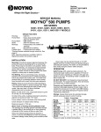
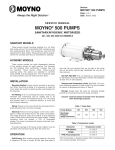
Section:
MOYNO® 500 PUMPS
Page: 1 of 4
Date: March 1, 1998
SERVICE MANUAL
®
MOYNO 500 PUMPS
300 SERIES
30100, 30102, 30104, AND 30105 MODELS
DESIGN FEATURES
Housing:
Phenolic
Pump Rotor: Phenolic
Elastomers: NBR, EPDM, FPM
Shaft:
Carbon steel
Bearings:
Prelubricated, fully sealed ball bearings
mounted on shaft and
integrally cast in pump body.
Seal:
Mechanical (carbon/ceramic)
Mounting:
Resilient mountings for quiet operation
Port Size:
1” OD for hose connections
INSTALLATION
Mounting Position. Pump may be mounted in any
position. When mounting vertically, it is necessary to keep
bearings above seals to prevent possible seal leakage into
bearings.
Pre-Wetting. Prior to connecting pump, wet pump
elements and mechanical seal by adding fluid to be
pumped into suction and discharge ports. Turn shaft over
several times in a counterclockwise direction to work fluid
into elements.
Piping. Install 1” ID hose using adjustable hose clamps. If
hose is lengthy, it should be supported to avoid excessive
strain on pump housings.
Drive. On belt driven units, adjust belt tension to point of
non-slip. Do not overtighten.
On direct drive units, coupling components should be
aligned and spaced at least 1/16” apart.
Note: Pump shaft diameter is .6267”. Pulley or coupling
may have to be hand reamed for proper fit.
Check rotation before startup. Rotation must be
counterclockwise when facing shaft to prevent rotor
unscrewing from shaft.
Maximum speed is 1750 rpm.
OPERATION
Self-Priming. With wetted pumping elements, the pump is
capable of 25 feet of suction lift when operating at 1750
rpm with hose size equal to port size. Be sure suction lines
are air tight or pump will not prime.
DO NOT RUN DRY. Unit depends on liquid pumped for
lubrication. For proper lubrication, flow rate should be at
least 10% of rated capacity at a given rpm.
Pressure and Temperature Limits. Maximum discharge
pressure is 25 psig. Unit is suitable for service at
temperatures shown in Table 1.
Storage. Always drain pump for extended storage
periods by removing suction and discharge lines, loosening
resilient mount clamps and turning discharge port to drain
position.
Table 1. Temperature Limits
Elastomer
*NBR
*EPDM
*FPM
Temperature Limits
10°-160°F
10°-210°F
10°-240°F
*NBR = Nitrile
*EPDM = Ethylene-Propylene-Diene Terpolymer
*FPM = Fluoroelastomer
TROUBLE SHOOTING
WARNING: Before making adjustments, disconnect
power source and thoroughly bleed pressure
from system. Failure to do so could result in
electric shock or serious bodily harm.
Replace belt or coupling guards before reconnecting power.
Failure To Pump.
1. Belt or coupling slip: Adjust belt tension or tighten set screw
on coupling.
2. Stator torn; possibly excessive pressure: Replace stator,
check pressure at discharge port.
3. Wrong rotation: Rotation must be counterclockwise when
facing shaft.
4. Threads in rotor or on shaft stripped: Replace part. Check
for proper rotation.
5. Excessive suction lift or vacuum.
Page 2
Pump Overloads.
1. Excessive discharge pressure: Check discharge pressure
for 25 psig maximum or obstruction in discharge line.
2. Fluid viscosity too high: Limit fluid viscosity to 20,000 CP
or 100,000 SSU.
Viscosity CP
1-300
300-1,000
1,000-2,000
2,000-5,000
5,000-10,000
10,000-20,000
Limit RPM
1750
1200
700
350
180
100
3. Insufficient motor HP: Check HP requirement.
Noisy Operation.
1. Starved suction: Check fluid level, size of piping, and
obstructions in pipe.
2. Bearings worn: Replace pump body.
3. Insufficient mounting: Check base for rigidity. Add support
if necessary.
Seal Leakage.
1. Leakage at startup: If leakage is slight, allow pump to run
several hours to let faces run in.
2. Persistent seal leakage: Faces may be cracked from
freezing or thermal shock. Replace seal.
Pump Will Not Prime.
1. Air leak on suction side: Check hose connections.
PUMP DISASSEMBLY
WARNING: Before disassembling pump, disconnect
power source and thoroughly bleed
pressure from system. Failure to do so
could result in electric shock or serious
bodily harm.
1. Disconnect power source.
2. Disconnect suction and discharge hoses. Loosen support
clamps (146) and remove pump from base (142).
3. Remove screws (112) which secure suction housing (2)
to pump body (1). Remove suction housing (2) and stator
(21).
4. Rotor (22) can be removed from shaft by turning in a
clockwise direction (LH thread).
5. Remove rubber washer and ceramic seal face from
shaft. Lift seal body out of seal bore in pump body. If any
parts of the mechanical seal (69) are worn or broken, the
complete seal assembly should be replaced. Seal
components are matched parts and are not
interchangeable.
6. The bearings and shaft assembly is molded into the
pump body and should not be removed. Pump body and
shaft are a complete part.
PUMP ASSEMBLY
1. Install mechanical seal (69) by oiling edge of seal body
and pressing into seal bore squarely and firmly. Apply
light oil to seal faces and slide ceramic face with rubber
washer onto shaft. Be sure rubber washer is completely
on shaft.
Caution: Do not use oil on EPDM parts. Substitute
glycerin or soap and water.
2. Screw rotor (22) onto shaft in a counterclockwise
direction (LH thread).
3. Install stator (21) on rotor, seating stator flange in
groove on pump body (1).
4. Assemble suction housing (2) to pump body (1). Do not
overtighten screws, and apply even pressure on all
screws so as not to strip threads in plastic housing.
5. Connect hoses and follow installation instructions.
WARNING: Replace belt or coupling guards before
reconnecting power.
Page 3
When ordering parts, please specify pump
model number, pump serial number, part
number, part description and quantity.
PARTS LIST
Item No. Description
30100
1
2
*21
Pump Body (Includes
Bearing and Drive Shaft)
Suction Housing
Pump Model Number
30102
30104
330-5311-000 (Phenolic)
330-0945-000
EPDM
340-3500-320
320-1486-000 (Phenolic)
320-1733-000
320-1734-000
320-6976-000
320-6977-000
320-6936-000
330-1697-000
320-4277-000
NBR
340-3500-120
Stator
*22
Rotor
64
Cushion Ring (2 req.)
64 A
Outer Ring (2 req.)
*69
Mechanical Seal
112
Screws (6 req.)
142
Pump Support
146
Clamp (2 req.)
*Recommended spare parts.
**30100 pump is the same as 30102, less base.
30105
**
**
**
**
NBR = Nitrile
EPDM = Ethylene-Propylene-Diene Terpolymer
FPM = Fluoroelastomer
FPM
340-3500-520
320-6978-000
Double The Length Of Your
Moyno Pump Warranty For FREE!
For your free pump warranty extension, choose from one of the three options below:
1. Go to www.moyno.com and fill out the registration form online
2. Mail this form by placing it in an envelope and sending it to: Moyno, Inc.
Attn: Tish Wilson
P. O. Box 960
3. Fax this form to 937-327-3177
Springfield, OH 45501-0960
U.S.A.
Thank you for choosing a Moyno Pump. Please take the time to complete this warranty registration form.Upon receipt
of your form, your standard limited warranty on defective material and workmanship will be extended to twice the standard
period of time at no additional cost to you. We appreciate your business and look forward to serving you in the future.
MOYNO
™
Always Insist on Genuine Moyno Replacement Parts!
Moyno® Pump Warranty Registration
Pump Model #
Pump Serial #
Purchased From
Date Purchased
Your Name
Your Title
Your Company Name
Address
City/State (Province)/Zip Code
Phone Number
Fax Number
E-mail
Application for Which This Pump Was Purchased
Material
Flow Rate
Process Temperature
Operating Speed
Viscosity
pH Value
Hours Operated per Day
Continuous
Intermittent
Discharge Pressure
Suction Pressure
NPSH Available
Percent of Solids
Particle Size
Abrasion Rating
How Did You First Hear of Moyno Pumps?
❑ Advertisement
❑ Distributor Salesperson
Thank You!
❑ Postcard
❑ Trade Show
❑ Previous Experience With Moyno Pumps
❑ Referral
❑ Other – Explain Below
© 1999 by Moyno, Inc.
® Moyno is a registered trademark of Moyno Inc.
Printed in U.S.A.