1
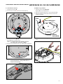
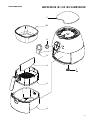
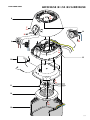
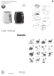
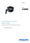
Air Fryer HD9225/50 HD9225/51 HD9225/52 HD9225/53 HD9220/50 Philips Consumer Lifestyle Service Manual PRODUCT INFORMATION TECHNICAL INFORMATION Safety info - This product meets the requirements regarding interference suppression on radio and TV. - After the product has been repaired, it should function properly and has to meet the safety requirements as officially laid down at this moment. - Voltage Frequency Power consumption Product dimensions (W x H x D) Cord length Materials : Outer skin : Pan : Basket : Basket mesh : Coating - Capacity : : : : : : : : : : : - Weight - Coloursetting : : - Temperature - Fuse cut-off temp. Motor TCO : : : - SAP coding : HD9225/50 HD9225/51 HD9225/52 HD9225/53 HD9220/50 OPTIONAL (accessories) - Baking dish 4222 459 52761 220 - 240 V 50 - 60 Hz 1425 W 287 x 315 x 384 mm 1 meter Plastic (PP) Aluminized steel Aluminized steel Stainless steel PTFE coating 2.2 liter (till max indicator) 7.0 kg Star white / Cashmere grey 80 till 200 °C 145 °C 190 °C IMPORTANT: When you replace the pan (basketholder) or basket, first check production week on the bottom of the appliance to find out which part(s) you need to order: HD9225/5x HD9220/5x Pan Basket 1111 4222 459 54161 and 4222 459 54151 Due to compatibility issues, make sure you order both components 1111 1136 4222 459 54161 or 4222 459 52711 Components are compatible no need to be ordered both at once 1136 4222 459 54161 or 4222 459 54151 Components are compatible no need to be ordered both at once Published by Philips Consumer Lifestyle 11/10 Printed in the Netherlands © Copyright reserved Subject to modification TROUBLE SHOOTING Part/ System Timer Thermostat Motor fan assy Heating element HD9225/50 /51 /52 /53/ HD9220/50 Replace (depending of the analyses outcome) Test Possible deviation Analyses Check if the green light is lit, and if you can hear the timer ticking The green light is not lit but the timer is ticking Check the timer-switch and the fuse with a multimeter Timer/Fuse The green light is lit but the timer is not ticking Timer is defective Timer Set the temperature at 80 °C and check if the heating element is getting warm (Check input power approx. 1425 W) The green light should be lit and the orange light should switch off after it reaches 80 °C Both green and orange light are lit but there is no heating Check the heating element with a multimeter Heating element If the green light is lit and the orange light is off Check the thermostat with a multimeter Thermostat If both the green and orange light are off Check the timer and fuse with a multimeter Timer/Fuse The orange light does not switch off after reaching approx. 80 °C Thermostat is defective Thermostat The fan is scraping the housing turning it by hand (Switch off the power when you do this test!) Motor fan assy The fan is not scraping the housing turning it by hand (Switch off the power when you do this test!): Check the motor fan assy, timer and fuse with a multi meter Motor fan assy / Timer/Fuse If the Orange light is on and the heating element does not heat Check the heating element with a multimeter Heating element If the heating element does not heat and the orange light is off Check the timer, fuse and thermostat with a multimeter Timer/Fuse/ Thermostat Green light is not lit Check the timer and fuse with a multimeter Timer/Fuse Set the timer and listen if the Motor is not running motor is running Check if the heating element is getting warm (Check input power approx. 1425 W) Thermal fuse Set the timer and check if the green light is lit 2-9 REPAIR INSTRUCTIONS HD9225/50 /51 /52 /53/ HD9220/50 General remark; When you need to disconnect a wire from the crimp housing, please cut the wire half way (See in the picture below) and always connect the wires with a new 2 wire crimp housing 4222 459 51851. To crimp the housing use the Lobster AK25 No2 or Muromoto Tekko MR30A Nr 2 with Air pressure = 6 kg/cm². Crimp instruction CE2 1) Strip wires: 16mm (0.63 in) Max. 13mm (0.51) Min. 2) Twist the wires together along the entire length of the strip and insert them into crimp housing . 3) Center the crimp tool on the sleeve. 4) Crimp the housing with 6 kg/cm². Route the wire route, using 5 tie-wraps according the picture below; 3-9 DISASSEMBLY- AND RE-ASSEMBLY ADVICE HD9225/50 /51 /52 /53/ HD9220/50 A. Top cover removal 1. Open the cover from the top cover by using a flathead screw driver to open the 6 click connections. 3. Use a flathead screw driver to open the “timer top cover” and pull the knob from the appliance. 4. Unscrew the screw B under the timer top cover. 2. Use a crosshead screw driver to unscrew the 4 screws A. Note: When you close the top cover, use a screw torque off 50 till 80 Nm (5 to 8 kgf.cm) B Note: Replace the timer cover and / or the cover in case of damage and / or scratches. Tip: Open the “timer cover” from the bottom side, to avoid scratches on visible places. A A A A 4-9 DISASSEMBLY- AND RE-ASSEMBLY ADVICE HD9225/50 /51 /52 /53/ HD9220/50 B. Cover housing removal D. Double heat shield removal 1. Follow previous step A 2. Open the motor fan assy from the base by unscrewing the 6 screws C. Be aware of the 2 screws under the filter. 1. Follow previous step A, B and C 2. Remove the double heat shield out of the motor fan assy by unscrewing the 3 screws E. C C C C C E E E C C. Heating element + Fan Removeval E. Timer removal 1. Follow previous step A and B 2. Undo the heating element from the double heat shield by unscrewing the 3 screws D. 1. Follow step A 2. Unscrew the 2 screws F behind the timer knob. D F D F 3. Remove the wires of the timer. D 3. Cut the 2 heating element wires halfway and remove the heating element. 4. Undo the nut from the left screw thread and remove the fan. 5-9 DISASSEMBLY- AND RE-ASSEMBLY ADVICE HD9225/50 /51 /52 /53/ HD9220/50 F. Thermostat removal G. Motor assy removal 1. Follow previous step A 2. Remove the 3 screws G from the thermostat assy. 1. Follow previous step A, B, C, D By step C do not cut the wires. 2. Remove the thermostat sensor (See instruction F 4) 3. Remove the fuse and the earth connection from the double heat shield. Fuse Earth connection G G G Double heat shield 3. Follow previous step B, C, D By step C do not cut the wires. Note: be careful with the wire / heating element connecting, this connection is fragile. 4. Remove the thermostat sensor by undoing the metal band. 4. Cut the motor wires half way and remove the motor fan assy. metal band Note: Please make sure while re-assembling the new thermostat that the routing will be done as shown in below picture. 6-9 HD9225/50 /51 /52 /53/ HD9220/50 PARTS LIST Pos Service code Description 1 2 3 4 5 4222 459 52771 4222 459 52691 4222 459 52701 4222 459 51901 4222 459 52711 4222 459 54151 Cover Timer knob Timer cover Food separator Basket 6 7 4222 459 52721 4222 459 51911 4222 459 54671 4222 459 52731 4222 459 53251 Pan (Basket holder) Rubber foot Rubber foot Top cover Stainless steel timer 4222 459 49181 4222 459 49141 4222 459 49131 4222 459 53391 4222 459 52741 Fuse incl. wires Fan Heating element incl. wires Heating element incl. wires Base incl. wires 4222 459 52751 4222 459 49201 4222 459 53401 4222 459 52761 Thermostat assy Motor, fan assy Motor, fan assy Baking dish 4222 459 51851 10 pieces of 2 wire crimp housing (CE-2) 8 9 10 11 12 13 14 15 16 * Cashmere grey Black Oyster Metellic wk1136 wk1136 wk1116 wk1116 Cashmere grey Star white Star white 220-240 V, 50 Hz 220-240 V, 60 Hz Star white 220-240 V, 50 Hz 60 Hz * Optional for HD9220/50 Electrical circuit When the appliance does not work, check the electrical circuit. Open de lid panel always on the underside. Always replaces this panel in case of damaged, scratches body or broken click connection. L BK RD BK BK BK BL BL Resistor 220 - 240 V 50 - 60 Hz Motor M WT N BL Thermostat BL WT Resistor Heater Green Neon lamp WT WT WT Orange Neon lamp WT Therm. Fuse E YL & GN YL & GN RD BK BL WT YL GN = = = = = = Red Black Blue White Yellow Green 7-9 EXPLODED VIEW HD9225/50 /51 /52 /53/ HD9220/50 1 16 2 3 4 7 4x 5 6 8-9 HD9225/50 /51 /52 /53/ HD9220/50 EXPLODED VIEW A 4x 8 F 2x 14 B G 3x 9 C 6x 15 10 E 3x 11 12 D 3x 13 9-9