1
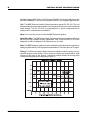
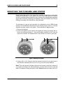
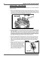
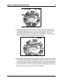
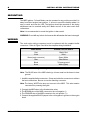
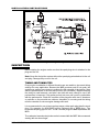
Installation Instructions PN KT4202 Honda TRX 250R The MSD Enhancer Ignition system, PN 4202, for the Honda TRX 250R ATV is designed as a complete system. No part may be substituted nor should any part be used with the stock ignition components. Note: To use the MSD Enhancer Ignition System the stock flywheel and stator assembly must be modified. This modification is not reversible. Parts Included: 1 - MSD Enhancer Control Unit, PN 4202 1 - MSD Pro CD Coil, PN 4295 1 - MSD Super Conductor Spark Plug Wire, PN 31009 1 - Parts Bag 1 - 24" Black 18 Gauge Wire 1 - 26" Violet 18 Gauge Wire 1 - 5/8" Long Heat Shrink 1 - MSD NiCad Battery Pack, PN 4381 Optional Replacement Battery & Charger * 7.2 Volt Radio Controlled (R/C) Car Battery * Radio Shack Slow Charger (120 ACV, wall socket) Radio Shack PN 23-241 (approx. 7 hours to charge) * MSD Fast Charger (12 DCV), PN 4385 (approx. 1 hour to charge) Note: It is recommended that you have the Service Manual for your quad during the installation. TECHNICAL INFORMATION The following explains some of the technical aspects of the Enhancer Ignition System. Modified Stator & Flywheel: The stock ignition stator and flywheel must be modified to obtain the best performance and the highest spark energy. This modification can be done by the installer as outlined later in this instruction manual or you may send your flywheel and stator to MSD Ignition to be modified. Call for pricing and current time for completion. Battery: The Enhancer Ignition depends on a 7.2 volt power source to supply power to the complex adjustable timing feature. The MSD NiCad Battery Pack, PN 4381, is completely sealed in a red Polyurethane potting compound. Although it will not hurt the ignition to leave the battery plugged in, it will put a slight drain on the battery which in time will cause the battery to go dead. The MSD Battery must be completely discharged before recharging. Radio Shack makes a slow charger, PN 23-241, that may be used with MSD NiCad Battery Pack. This charger is a 120 volt wall unit that charges in approximately seven hours. MSD IGNITION 12120 ESTHER L AMA, SUITE 114, EL PASO, TEXAS, 79936 (800) 392-2842 FAX (915) 858-9241 2 INSTALLATION INSTRUCTIONS For field charging MSD offers a Fast Charger, PN 4385. This charger will charge the MSD NiCad Battery in one hour from any automotive 12 volt cigarette lighter outlet. Coil: The MSD Enhancer Ignition System includes a special Pro CD Coil. This coil has an extremely low primary resistance and a high turns ratio to produce maximum spark energy. The Pro CD Coil is encapsulated in a rynite compound that is impervious to contaminates and vibration. Note: Do not use the stock coil with the MSD Enhancer Ignition. Spark Plug Wire: The MSD 8.5mm Super Conductor wire has low resistance (50 ohms per foot) for high voltage carrying capabilities, with a high amount of RF noise suppression that is equivalent to a 1500 ohms per foot wire. Note: The MSD Enhancer Ignition must be used with a helically wound, suppression spark plug wire with RF noise suppression equivalent to 700 ohms per foot or higher. Timing: The Enhancer Ignition allows the user to adjust the ignition timing curve to optimize engine power output. This is done by rotating the potentiometer shaft located on the back of the ignition. Clockwise rotation retards the timing while counterclockwise advances the timing (Figure 1). Figure 1 The Adjustable Ignition Timing Curve. MSD IGNITION 12120 ESTHER L AMA, SUITE 114, EL PASO, TEXAS, 79936 (800) 392-2842 FAX (915) 858-9241 INSTALLATION INSTRUCTIONS 3 MODIFYING THE FLYWHEEL AND STATOR Please review this section of the instructions carefully. If you are not comfortable making this modification to your system, you may contact MSD Ignition for a price quote on completing this procedure for you. You may use an aftermarket adjustable trigger plate instead of modifying your flywheel. These are available from Duncan Racing, part number HR-1008, phone: (619) 258-6306. The following is a step by step instruction for modifying the stock (OEM) Honda flywheel. This modification will advance the stock timing curve a total of 7°. This will optimize the power output of the engine. The modification is not reversible. 1. Remove the flywheel. 2. Position the flywheel so the outside of the flywheel is facing you and the tab on the rim is pointing up (Figure 2). Using a dial caliper, measure in 0.273" from the right side of the tab. This measurement is very critical so be sure to get it right. Figure 2 Modifying the Flywheel. 3. Using a mill or a file, shave the tab from the right to the left. As you get closer to the mark take measurements so you do not go over the correct distance. Note: This is the amount of advance that we have found to work best, however if you require the timing to be advanced further you may shave off more of the tab width. One degree of timing is equal to 0.039". Do not remove more than 0.39" (10°). MSD IGNITION 12120 ESTHER L AMA, SUITE 114, EL PASO, TEXAS, 79936 (800) 392-2842 FAX (915) 858-9241 4 INSTALLATION INSTRUCTIONS MODIFYING THE STATOR Remove the stator assembly from the engine and secure it so it can be worked on without it moving. 1. Place the two black windings (with tape sealer) facing away from you (Figure 3). Locate the two black solder posts directly below the left black winding. The post to the left is the one we will be dealing with. This post may be coated with a black sealer. This will burn off when applying the soldering gun. Figure 3 Locating the Soldering Post of the Stator. 2. Soldered to this post is a very small wire that must be removed. NOTE: DO NOT CUT THIS WIRE. This wire will be reattached to the supplied VIOLET wire which will be run out of the stator cover. Very carefully heat this terminal with a soldering iron until the solder starts to melt. Then take a small pair of needle nose pliers and pinch the terminal teeth together. This will allow the small wire to slide off the post. While still heating the post pull the wire gently off the post. 3. Route the supplied VIOLET wire through all of the stock stator grommets and sleeves. The wire will be run along side one of the stock stator wire grommet holes. This procedure will be easier if a light lubricant is used. Route this wire between the right side black stator winding and the first heavy wire winding (Figure 4). 4. Position the VIOLET wire so it runs flat between the stator windings and up to the wire that you removed from the stator in Step 3. Strip approximately 1/4" of the insulation from the VIOLET wire and slide the supplied heat shrink tubing over the wire (Figure 5). Figure 4 Routing the Violet Wire. MSD IGNITION 12120 ESTHER L AMA, SUITE 114, EL PASO, TEXAS, 79936 (800) 392-2842 FAX (915) 858-9241 INSTALLATION INSTRUCTIONS 5 Figure 5 The Violet Wire in Place on the Stator. 5. Solder the wire that you removed from the stator to the VIOLET wire. With an ohm meter check to make sure you have continuity between the VIOLET wire and the BLACK/RED wire coming out of the stator harness. The correct measurement should be 50 - 250 ohms. Also check that there is no continuity between the VIOLET wire and the steel stator assembly. 5 Figure 6 Sealing the Connection. 6. Slide the heat shrink tubing over the soldered connection. Heat the shrink tubing with a heat gun just enough to induce shrinking. After the connection has cooled, position the connection as close and tight as possible to the stator assembly and cover it with E-6000 or Goop brand sealer (Figure 6). Apply sealer wherever the wire may come loose. This is very important so that the wire doesnt vibrate loose. 7. After the sealer has dried, install the stator and flywheel. MSD IGNITION 12120 ESTHER L AMA, SUITE 114, EL PASO, TEXAS, 79936 (800) 392-2842 FAX (915) 858-9241 6 INSTALLATION INSTRUCTIONS MOUNTING The MSD Ignition, Coil and Battery can be mounted in any position provided it is away from direct engine heat sources. It is best to mount the battery where it is easy to reach and view the LED. The Ignition should be mounted so the timing adjustment can be reached easily also. Make sure all of the wires reach their connections. Note: It is recommended to mount the ignition to bare metal. WARNING: Do not drill any holes in the frame as this will weaken the frames strength. WIRING The stock stator wiring connectors must be replaced with the supplied bullet connectors. Refer to Figure 7and 8 for the complete wiring installation. MSD WIRES Red Violet Green (male connector) Blue Black None HONDA STATOR WIRES Black/ Red Violet Green /White Blue/Yellow To frame ground White (lights) Figure 7 Wiring Installation Chart. Note: The BLACK wire of the MSD should go to bare metal on the frame for best ground. 1. Install the supplied bullet connectors. Crimp and solder the connectors to achieve the best connections. Be sure to use the matching connector. Note: The factory WHITE wire does not connect to the MSD. This wire remains connected for powering the lights. 2. Connect the MSD wires to the Honda stator wires. 3. The BROWN wire of the MSD connects to the coil negative (-). 4. The ORANGE wire of the MSD connects to the coil positive (+). 5. Connect the supplied BLACK jumper to the coil negative to ground on the engine head. MSD IGNITION 12120 ESTHER L AMA, SUITE 114, EL PASO, TEXAS, 79936 (800) 392-2842 FAX (915) 858-9241 INSTALLATION INSTRUCTIONS 7 Figure 8 Wiring the MSD Ignition. INSPECTION Before starting the engine, make sure that the spark plug wire is attached to the plug and the coil. Note: Never fire the ignition system without the spark plug wire attached to the coil and plug. Damage may occur to the coil. TIMING AND TUNING TIPS Every engine combination is different therefore we are unable to give exact timing settings for every application. Because the MSD produces such a hot spark, the engine may require some tuning to achieve the full potential of the ignition. Start with the potentiometer in the full retard position (full clockwise). Begin advancing the timing in small amounts, and take a test ride with each change to see if the performance is improved. Only perform short test runs until you are comfortable with the performance. Check the condition of the plug after each test. If aluminum or particles on the porcelain are obvious, detonation is occurring and the timing must be retarded or serious engine damage will result. It is recommended to run at least one heat range colder spark plug than the stock plug. For example: An NGK B8ES will be replaced with a B9ES plug. The recommended plug gap is 0.032" - 0.036". Resistor plugs are not required with the MSD. The carburetor low and main jet size can be increased with the MSD. We recommend starting with two sizes larger. MSD IGNITION 12120 ESTHER L AMA, SUITE 114, EL PASO, TEXAS, 79936 (800) 392-2842 FAX (915) 858-9241 TECH NOTES ________________________________________________________________________________________________________________________ ________________________________________________________________________________________________________________________ ________________________________________________________________________________________________________________________ ________________________________________________________________________________________________________________________ ________________________________________________________________________________________________________________________ ________________________________________________________________________________________________________________________ ________________________________________________________________________________________________________________________ ________________________________________________________________________________________________________________________ ________________________________________________________________________________________________________________________ ________________________________________________________________________________________________________________________ ________________________________________________________________________________________________________________________ ________________________________________________________________________________________________________________________ ________________________________________________________________________________________________________________________ ________________________________________________________________________________________________________________________ ________________________________________________________________________________________________________________________ ________________________________________________________________________________________________________________________ ________________________________________________________________________________________________________________________ Service In case of malfunction, this MSD component will be repaired free of charge according to the terms of the warranty. When returning MSD components for service, Proof of Purchase must be supplied for warranty verification. After the warranty period has expired, repair service is charged based on a minimum and maximum charge. Send the unit prepaid with proof of purchase to the attention of: Customer Service Department, Autotronic Controls Corporation, 12120 Esther Lama, Suite 114, El Paso, Texas 79936. When returning the unit for repair, leave all wires at the length in which you have them installed. Cutting wires close to the unit will void your warranty. Be sure to include a detailed account of any problems experienced, and what components and accessories are installed on the vehicle. The repaired unit will be returned as soon as possible after receipt, COD for any charges. For more information, call the MSD Customer Service Line 1(800) 392-2842. MSD technicians are available from 8:00 a.m. to 5:00 p.m. Monday - Friday (mountain time). A Limited Warranty utotronic Controls Corporation warrants MSD Ignition products to be free from defects in material and workmanship under normal use and if properly installed for a period of one year from date of purchase. If found to be defective as mentioned above, it will be replaced or repaired if returned prepaid along with proof of date of purchase. This shall constitute the sole remedy of the purchaser and the sole liability of Autotronic Controls Corporation. To the extent permitted by law, the foregoing is exclusive and in lieu of all other warranties or representations whether expressed or implied, including any implied warranty of merchantability or fitness. In no event shall Autotronic Controls Corporation be liable for special or consequential damages. MSD IGNITION FRM18599 12120 ESTHER L AMA, SUITE 114, EL PASO, TEXAS, 79936 (800) 392-2842 FAX (915) 858-9241 Revised 06/97 Printed In U.S.A.