1
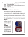
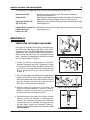
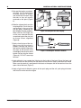
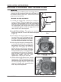
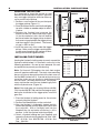
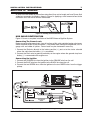
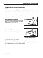
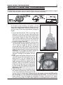
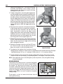
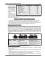
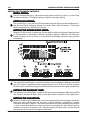
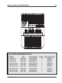
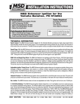
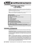
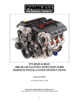
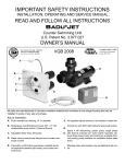
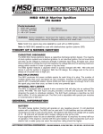
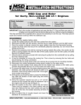
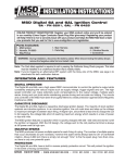
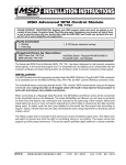
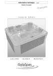
MSD Watercraft Ignition System
PN 4242, 4243, 4244
IMPORTANT: Read these Instructions before attempting the installation!
WARNING:
During installation, disconnect the battery cables. When disconnecting the battery, always remove
the Negative cable first and install it last.
Parts Included In This Kit
1 - MSD Watercraft Ignition PN 4272
1 - Ignition Coil, PN 4292
1 - Ignition Wire Set, MSD Super Conductor, PN 31009
1 - Trigger Pickup, PN 4316
1 - Trigger Plate, Kaw 650/750 PN 4312, Yam: 650/701/760 PN 4311, Sea Doo 720: PN 4328
1 - Flywheel, Kaw. 650/750 PN 4302, Yam. 650/701/760 PN 4303, Sea Doo 720: PN 4304
1 - Shim Kit, 2 - .020 Shims, 1 - .060 Shim, PN 4318
1 - Grommet, Kaw. 650/750 PN 4321, Yam. 650/701/760 PN 4322
1 - 18 ga. Violet Wire
6 - Perma Seal Ring Lug Terminals, 3-No. 6, 2-No. 10, 3 - 5/16"
8 - Perma Seal Butt Connectors, 18-22 Ga.
2 - 4/40 3/8" Phillips Screws
2 - 4/40 1/2" Phillips Screws
1 - 3mm x 5mm Woodruff Key (Kaw. 650/750 Models Only)
1 - 3mm x 3.6mm Woodruff Key (Sea Doo Only)
1 - 5mm x 6.5mm Woodruff Key (Yam. 650/701/760 Models Only)
2 - 6mm x 20mm Button Head Stainless Bolts (Kaw. 650/750 & Yam. 650/701/760 Models Only)
2 - 14 x 6.4mm Compression Washer ( Kaw. 650/750 & Yam. 650/701/760 Models Only)
Parts Not Included But May Be Required
Ignition Mounting Plates:
1 - Starter Relay, MSD PN 4390
Kawasaki 750 SX, SXi, PN 4395
1 - Waterproof On/Off Switch, MSD PN 4370
Yamaha Super Jet, Blaster, VXR,
1 - MSD Ignition Kill Lanyard, PN 43731
Wave Raider, WaveRunner, PN 4396
1 - Momentary On/Off Switch, MSD PN 4372
All Sea Doo, PN 4397
Tools Required
1 - 4mm Allen Wrench
1 - Phillips Screw Driver
1 - 1/2" Drive Rachet
1 - 1/2 x 30mm Socket (Sea Doo Only)
1 - 1/2 x 14mm Socket (650/750 Kaw. Eng. Only)
1 - 1/2 x 17mm Socket (650/701 Yam. Eng. Only)
1 - Torque Wrench
MSD IGNITION
1 - Wire Terminal Crimper
1 - Heat Gun
1 - Caliper or Measuring Device
1 - Clay or Soft Wax
1 - Flywheel Puller
1 - Flywheel Holder
1 - Single Edge Razor Blade
• 12120 ESTHER LAMA, SUITE 114, EL PASO, TEXAS 79936 • (915) 857-5200 • FAX (915) 858-9241
2
INSTALLATION INSTRUCTIONS
For ease of installation, these instructions are divided into sections.
Section I:
Mounting the Ignition, Coil and Starter Relay
Section II:
Installing the Spark Plug Wires
Section III:
Installing the Flywheel and Trigger Pickup Assembly
Section IV:
Wiring the Ignition System, Cable Identification, Connecting the Power Leads
Section V:
Timing the Ignition, Programming the Ignition
Section VI:
Troubleshooting
Section VII:
Customer Service & Warranty
SECTION I
MOUNTING THE IGNITION, COIL, STARTER RELAY
The MSD Watercraft Ignition may be mounted in any location except on the engine or near the
exhaust manifold. Excessive heat at these locations could damage the ignition.
It is recommended that a mounting plate be fabricated out of aluminum or stainless steel and
the ignition, coil and starter relay be mounted to it. Use the template supplied to assist you in
making a mounting plate for your craft. When selecting a mounting location make sure that the
ignition’s cable assembly will reach the battery and flywheel areas.
To simplify installation, MSD offers mounting plates for most applications (Figure 1). These
strong aluminum plates are pre-drilled and attach to the factory mounting locations. Part numbers
are listed on page 1.
Ignition
Using the Ignition as a template, mark the location of the mounting holes on the mounting
plate. Remove the ignition and drill a 1/4" hole at each marked location. Mount the ignition
using 10-32 x 3/4" or 5mm x 16mm stainless steel bolts (not supplied).
Ignition Coil
Using the coil as a template,
mark the location of the
mounting holes. Remove the coil
and drill a 1/4" hole at each
marked location. Mount the coil
using 1/4" x 3/4" or 6mm x 20mm
stainless steel bolts (not
supplied).
Starter Relay
When installing the MSD
Watercraft Ignition System it may
be necessary to remove the
stock starter relay and replace it
with an MSD External Relay, PN
4390. Using the relay as a
template mark the location of the
mounting holes. Remove the
relay and drill a 1/4" hole at each
marked location. Mount the coil
using 1/4" x 1/2" or 6mm x 12mm
stainless steel bolts (not
supplied).
MSD IGNITION
Figure 1 An MSD Mounting Plate.
• 12120 ESTHER LAMA, SUITE 114, EL PASO, TEXAS 79936 • (915) 857-5200 • FAX (915) 858-9241
INSTALLATION INSTRUCTIONS
3
The following are suggested areas to install the mounting plate to your craft.
Kawasaki 650 SX
Kawasaki X2
Kawasaki 750 SX, SXi
SS, Xi, Xir, Zxi
Yamaha Blaster, SuperJet
VXR/WaveRunner,
Raider 701/760
Remove the stock electrical box and mount the plate to
existing mounting bosses.
Attach ignition mounting plate under the hood latch mounting
bolts. Mount coil above engine next to the steering arm.
Remove the stock electrical box and mount the plate to existing
mounting bosses.
Remove the stock electrical box and mount the plate to existing
mounting bosses.
SECTION II
INSTALLING THE SPARK PLUG WIRES
Each wire set includes two 90° dual crimp terminals,
two MSD Heli-Core Spark Plug Wires and a MiniStripper-Crimper. The MSD Mini-Stripper-Crimper is
supplied for assembling the MSD Spark Plug Wires.
Before using the tool it must be separated into two
parts. Separate it by bending the tool back and forth
until the center breaks (Figure 2).
1. Locate the correct cutting groove of the MiniStripper-Crimper for your wire. One groove is larger
to accept the 8.5mm Super Conductor Wire. Insert
the wire from the long side of the crimper tool and
push it through until it is flush with the other side
(Figure 3).
Figure 2 Separating the Mini-Stripper.
Figure 3 Stripping the Wire.
2. Press a single edge razor blade in the cutting groove
and push all the way down. Slowly rotate the wire
360° then remove the razor blade. Remove the wire
from the Crimper and slowly twist the cut end of
wire off in a counterclockwise direction.
3. Before crimping the terminals to the wires the
terminals must be modified as shown in Figure 4.
Bend the terminal ears over 90° by using a pair of
regular needle nose or long nose pliers.
4. Position the wire in the terminal until the insulation
sleeve is about 1/8" beyond its crimping tabs.
Position the conductor between the conductor
crimps and use a pair of needle nose pliers to crimp
the tabs tightly against the conductor (Figure 5).
Make sure the conductor does not slide out and do
not overtighten.
MSD IGNITION
Figure 4 Preparing the Terminals.
Figure 5 Installing the Terminal.
• 12120 ESTHER LAMA, SUITE 114, EL PASO, TEXAS 79936 • (915) 857-5200 • FAX (915) 858-9241
4
INSTALLATION INSTRUCTIONS
5. After positioning the conductor,
position the terminal/wire
assembly into the "W" groove
side of the Mini-Crimper. Align
the tabs so they are exactly
centered on the point (Figure
6).
6. Slide the stripper block over the
crimping block. Push the wire
and terminal in the rest of the
way by lightly squeezing the
Mini-Stripper-Crimper together.
Make sure the "Vise Flags" are
on the same side and that they
are pushed against the vise jaws
to ensure correct alignment
(Figure 6).
7. Slowly close the jaws of the vise.
Make sure that the crimp is
properly forming and that the
tool remains aligned. Stop when
the ends of the terminal have
curled tightly into the wire sleeve
but do not tear into the sleeve
(Figure 6). DO NOT overcrimp
the wire!
Figure 6 Installing the Wire and Crimping.
Figure 7 Postioning the Terminal in the Boot.
8. Apply dielectric (non conductive) lubricant to the inside of the boot. Grasp the boot and
push the wire with the terminal into the boot until the terminal stops at the boot's 90° bend.
Make sure the terminal is positioned in the boot so the open side of the terminal faces the
open side of the boot (Figure 7).
9. Apply a light coat of dielectric grease to the spark plug and the coil spark plug wire tower
and install the wire onto the engine.
MSD IGNITION
• 12120 ESTHER LAMA, SUITE 114, EL PASO, TEXAS 79936 • (915) 857-5200 • FAX (915) 858-9241
INSTALLATION INSTRUCTIONS
5
SECTION III FLYWHEEL AND TRIGGER PLATE
REMOVAL
Before installing the MSD Flywheel and Trigger Pickup
assembly, the stock magneto flywheel and stator plate must
be removed. Refer to your craft’s service manual for the
proper removal procedure.
TRIGGER PLATE ASSEMBLY
1. Assemble the trigger plate and pick-up assembly as
shown in Figure 8. Place the trigger plate assembly on
the bosses with the trigger on the side of the engine
where the wires normally exit the case (Figure 9). Screw
the supplied bolts and compression washers into the
case and lightly tighten to hold the trigger plate in the
center of the case's mounting pads.
Kawasaki 750 installation: The engine case mounting
pads of the Kawasaki 750 must be drilled and tapped
(Figure 10).
Figure 8 Assembling the Trigger
Plate.
A. Drill and tap a hole on each pad 2.165" from
the center of the case. Drill and tap each hole
for a 6mm x 1mm allen head bolt using a No.
9 or 5mm drill bit and a 6mm x 1mm tap.
Each hole needs to be drilled 21mm deep.
B. Rotate the plate through the slotted positions
to ensure that the plate slides smoothly and
does not rock. If resistance is felt remove the
trigger plate and inspect the mounting
bosses for burrs and file flat if necessary.
Note: The PN 4312 Kawasaki 650/750 Trigger
Plate outside diameter is machined to fit the
mounting pads on the Kawasaki 750 engine.
When this plate is used on a Kawasaki 650
engine the trigger plate will have
approximately 1/16" play on each side.
Figure 9 Mounting the Trigger Plate
Assembly.
2. Slide the Green trigger pickup wires through
the grommet. Install the grommet with wires
attached in the case and secure in place using
the stock mounting hardware. Place a small
amount of silicone sealer around the wires
where they enter the grommet.
Figure 10 Modifying the Kawasaki 750 Case.
MSD IGNITION
• 12120 ESTHER LAMA, SUITE 114, EL PASO, TEXAS 79936 • (915) 857-5200 • FAX (915) 858-9241
6
INSTALLATION INSTRUCTIONS
CHECKING THE AIR GAP
It is important to have the correct air gap
between the pickup and the flywheel. Too much
may not trigger the ignition while too little may
cause contact to the pickup.
1. Position a small amount of clay on the top of
the trigger pickup (Figure 11).
2. Place the flywheel on the crankshaft and lightly
tap with a rubber or wooden object to hold it
in place.
3. Remove the flywheel and measure the
thickness of the clay. Refer to the chart (Figure
12) for the number of shims that will need to
be placed under the trigger pickup to obtain
the correct air gap between the trigger pickup
and the magnet in the flywheel. The correct
air gap is .050" to .094".
4. Insert the necessary shims under the trigger
pickup. Make sure the trigger retaining bolts
are the correct length for the number of shims
being used and are tightened firmly.
INSTALLING THE FLYWHEEL
Heating the flywheel in boiling water to evenly expand the
flywheel material before it is installed is necessary in the
following procedure. Be sure to wear adequate skin and
eye protection to prevent possible burning.
Note: On Kawasaki 750 engines the stock front engine
cover will require modification. The stock stator mounting
bosses will have to be machined out of the front cover so
that the MSD flywheel will fit. If you do not have access to
a machine shop, you can also use a stock Kawasaki 650
SX front cover. To modify the Kawasaki 750 flywheel
cover, machine the areas that are shaded in gray flush
with the flywheel cover (Figure 13).
Figure 11 Checking the Air Gap.
SHIM CHART
If the thickness
of the clay is
between:
.050" - .094"
.095" - .115"
.116" - .135"
.136" - .155"
.156" - .176"
.176" - .195"
ADD THESE SHIMS
.020"
.060"
0
1
2
0
1
2
0
0
0
1
1
1
Figure 12 Air Gap Shim Chart.
Note: If the starter gear was removed (Kawasaki 650/
750, Yamaha 650/701/760 and Sea Doo engines only)
during the installation of the trigger plate, install the
gear now.
1. Place the flywheel in boiling water for five minutes
to evenly heat the flywheel.
2. Position the Woodruff Key on the crankshaft.
3. After the flywheel is thoroughly heated, quickly
remove the flywheel from the water and install it onto
the crankshaft. With a flashlight, look into the
Woodruff Key slot and make sure the key is still in
position. Install the flywheel retaining nut/bolt.
4. Attach a flywheel holding tool (not supplied) and
torque the flywheel retaining bolt/nut to: Kaw. 650/
750 - 65 ft-lbs; Yam. 650/701/760 - 65 ft-lbs; Sea
Doo - 100 ft-lbs.
MSD IGNITION
Figure 13 Modifying the Kawasaki 750
Front Cover.
• 12120 ESTHER LAMA, SUITE 114, EL PASO, TEXAS 79936 • (915) 857-5200 • FAX (915) 858-9241
INSTALLATION INSTRUCTIONS
7
SECTION IV WIRING
All wires must be routed to the locations described, then cut to length and have Perma-Seal
solderless connectors installed as shown in Figure 14. Applying a small amount of heat to the
connector seals the wire to terminal connection.
Figure 14 Installing Perma-Seal Connectors.
MSD CABLE IDENTIFICATION
Figure 15 shows a complete installation of the MSD Watercraft Ignition System.
Connecting The Power Leads
Before connecting the power leads, clean all surfaces of dirt, paint and other foreign substances
where the power leads will be connected . If the power leads need to be lengthened, use 14
gauge. wire and solder all splices. Power leads may be shortened if necessary.
1. Connect the Red wire directly to the battery positive (+) post or to the starter solenoid
where the cable from the battery (+) is connected.
2. Connect the Black wire to ground, preferably on the engine where the ground strap from
battery (-) is connected to the engine case.
Connecting the Ignition
1. Connect the ORANGE wire from the ignition to the ORANGE wire from the coil.
2. Connect the BLUE wire from the ignition to the BLACK wire from the coil.
3. Connect the two GREEN wires from the ignition to the two GREEN wires from the trigger
pickup.
Figure 15 Wiring the MSD Watercraft Ignition System.
MSD IGNITION
• 12120 ESTHER LAMA, SUITE 114, EL PASO, TEXAS 79936 • (915) 857-5200 • FAX (915) 858-9241
8
INSTALLATION INSTRUCTIONS
Note:It does not matter which Green wire on the ignition is hooked to which Green wire on
the trigger pickup.
CONNECTING THE FACTORY STOP SWITCH
PN 4272:
To retain use of the factory stop switch located on the handle bar, attach the two wires coming
from the stop switch to the two GREEN wires from the MSD Ignition (Figure 15).
Note: Sea Doo uses factory Landyard Switch to kill the engine. See Lanyard Switch hookup
below.
CONNECTING THE IGNITION KILL LANYARD FEATURE
Landyard Switches are listed as Normally Open or Closed when the switch is not connected to
anything and the Landyard is removed from the switch.
Normally Open Lanyard Switch
Connect the Violet wire of the MSD Ignition to one side
of the N.O. Lanyard Switch and the other side to
positive battery (12 volts) (Figure 16).
Figure 16 Normally Open Lanyard Switch.
CONNECTING THE HOLESHOT FEATURE
Connect the WHITE wire to one side of a normally
open momentary switch and the other side of the
switch to the BLACK wire (Figure 17).
Figure 17 Connecting the Holeshot
Feature with a Normaly Open Switch.
CONNECTING A TACHOMETER
The tach signal from the MSD is a 12 volt square wave signal so many types of tachometers can
be used with the ignition. Some of the more commonly used tachometers are the Jetmeter, Water
Strike Marine, Optak, J.R. Electronics, VDO, Faria, and Autometer. Connect the tachometer trigger
wire to the MSD ignitions Gray wire as shown in Figure 15.
MSD IGNITION
• 12120 ESTHER LAMA, SUITE 114, EL PASO, TEXAS 79936 • (915) 857-5200 • FAX (915) 858-9241
INSTALLATION INSTRUCTIONS
9
SECTION V TIMING AND PROGRAMMING
The MSD Watercraft Ignitions innovative design allows you to static time the engine before the engine
is started. Study the special features shown in Figure 18 before proceeding.
Figure 19 How to Check Static Timing
At this point in the installation, the ignition, coil and
starter relay should be mounted and installed in the craft
along with the trigger plate assembly and flywheel. Now
you are ready to time the engine before starting the
engine.
1. Locate Top-Dead-Center (TDC) by placing a dial
indicator in the front cylinder and rotating the
crankshaft until the piston reaches the highest point
in the cylinder (Figure 19). When TDC is found, place
a mark on the engine case so that it lines up with the
TDC mark of the far left timing mark on the flywheel
as shown in figure (Figure 20).
2. Remove the ignitions backing plate. Position switch
1 to ON/ON/ON. Position selector S4 of switch 2 to
"ON" in order to disable the ignition's spark and
activate the built-in LED indicator. Turn the ignition
on/off switch to the ON position and place the spark
plugs with spark plug wires attached against ground.
WARNING: Do not trigger the ignition without the
Figure 19 Finding Top Dead Center.
spark plugs grounded and the plug wires
attached. Damage to the ignition coil may
result.
3. Slowly rotate the flywheel clockwise until the
small LED on the side of the ignition turns on.
When the LED is on, this indicates that the
magnet on the flywheel is entering over the
trigger pickup and that the ignition will fire at
this point. Note: As the flywheel is rotated the
timing marks will decrease from a high number
to a low number. Each dimple on the flywheel
represents 5° of timing adjustment with the first
dimple being TDC.
4. Follow the timing mark on the engine down to
Figure 20 Marking TDC.
the flywheel and determine where the timing
is set at by reading the timing mark on the
flywheel. Write this number down. (Because of the advanced circuitry in the MSD Ignition
the true timing is 5° less than what the timing mark will show). To achieve your true
timing, subtract 5° from the number you wrote down. Example - shown 30° less 5° equals
25° of true timing. Note: the MSD Digital Ignition can be programmed to electronically
MSD IGNITION
• 12120 ESTHER LAMA, SUITE 114, EL PASO, TEXAS 79936 • (915) 857-5200 • FAX (915) 858-9241
10
INSTALLATION INSTRUCTIONS
retard the timing up to 7° less than what the
maximum true timing is set at. Always set the
trigger plate for the maximum amount of timing
the engine will ever run at.
5. To adjust the ignition's max timing the trigger plate
must be rotated counter-clockwise to advance the
timing or clockwise to retard the timing. To adjust
the plate without removing the flywheel, locate
the four trigger plate access holes in the flywheel
(Figure 21). Rotate the flywheel back to TDC and
then insert two 4mm allen wrenches into the holes
that line up with the trigger plate hold down bolts.
Loosen the bolts to allow the trigger plate to be
rotated.
6. Remove the two wrenches and rotate the flywheel
to the timing mark that was previously recorded.
Insert the two allen wrenches into the other two
holes (located 90° to the first two holes) so the
trigger plate rotates with the flywheel. Rotate the
flywheel clockwise or counter clockwise until the
desired timing mark on the flywheel lines up with
the timing mark on the engine (Figure 22).
Figure 21 Loosening the Trigger Plate.
7. Remove the two wrenches and rotate the flywheel
to TDC. Insert the allen wrenches into the first two
holes that line up with the trigger plate retaining
bolts and tighten the bolts.
8. Rotate the flywheel clockwise until the LED turns
on. Check to make sure the desired timing has
been set correctly. Install the flywheel cover.
Figure 22 Moving the Trigger Plate to
Adjust the Timing.
9. To program the engines final maximum timing
setting, position selectors S1-S3 of switch as required to match the desired timing. Example
- indicated timing is 25° less -3° (selectors S1-S3 set for 3°) = 22° maximum timing.
10. Turn the ignition switch to the OFF position and position selector S4 of switch 2 to off
position. Install the spark plugs and spark plug wires. The engine is now ready to start.
Note: If the application you are installing the system on permits, verify the ignition timing
using a timing light.
PROGRAMMING
The function of the timing curve is to match the ignition
to the burning rate of the fuel and the speed (RPM) of
the engine. By adjusting the timing of the ignition
maximum combustion pressure can be achieved at the
same time the piston is beginning the power stroke. Any
factor that changes the burning rate of the fuel or the
engine speed (RPM) can cause a need for an ignition
timing change.
To the right is a chart of some of the factors that will
affect ignition timing.
MSD IGNITION
Figure 23 Programming Points.
• 12120 ESTHER LAMA, SUITE 114, EL PASO, TEXAS 79936 • (915) 857-5200 • FAX (915) 858-9241
INSTALLATION INSTRUCTIONS
11
As you can see
FACTOR
ADVANCE FOR
RETARD FOR
from the chart, most
Cylinder
Pressure
Low
High
factors will change
RPM
Engine
Low
High
throughout the range
Energy
of
Ignition
Low
High
of engine operation.
Fuel
Octane
High
Low
Timing adjustments
Mixture (Fuel/Air)
Rich
Lean
must be made to
Temperature
Cool
Hot
compensate for these
Combustion Turbulence
Low
High
changes.
Load
Light
Heavy
Obviously, a full
technical explaination
of the correct ignition timing would be very complicated. The best way to arrive at a suitable
timing curve for your engine is to use the above chart as a guide and compare your engine
combination against the chart.
TIPS FOR SET
TING YOUR IGNITION TIMING
SETTING
1. Use as much initial advance as possible without encountering excessive starter load or
engine kickback on starting. Beware of detonation when setting the initial advance.
2. Set the timing retard start point as early as possible without sacrificing low RPM performance.
3. Use the highest retard as possible without hurting top end performance.
PROGRAMMING THE IGNITION
The MSD Ignition produces a computer-generated timing curve. Several programming options
are available to tune the basic timing curve to meet specific engine requirements. The factory
program settings are suitable for most watercraft, but changes can be made for special
applications. Three switches located under the aluminum plate of the MSD ignition module
select the programming options (Figure 24). IMPORTANT NOTE: If the selector switch
settings are changed, the ignition switch must be turned "off" and back "on" before the
new program functions become active. Always install aluminum backing plate to seal
switches.
The factory settings are:
Switch 1
Selectors
S1-on, S2-on, S3-on
Switch 2
Selectors
S1-off, S2-on, S3-off
S4-off
S5-on, S6-off, S7-on, S8-off
Switch 3
Selectors
S1-off, S2-on, S3-off, S4-off
S5-on, S6-on, S7-on, S8-off
(Max Timing = 0°)
(Begin Retard = 5000 rpm)
(Timing Setup = Ignition Operate)
(Rev Limit = 7750 rpm)
(Holeshot Rev Limit = 3500 rpm)
(Max Speed Retard = 7°.)
Figure 24 Programming Switches
TIMING RET
ARD FUNCTION
RETARD
The max speed retard function is an rpm-dependent timing retard. It is configured by three
seperate elements:
1. The "Retard Begin Speed" (C) Fig. 25 is the point in the rpm range when the timing retard
begins.
2. The "Total Retard" (F) Fig. 25 is the total amount of timing retard (in crankshaft degrees)
introduced between the retard begin point and the Rev Limit point.
3. The "Rev Limit" (D) Fig. 25 is the point in the rpm range where maximum safe engine rpm
limit is set and where the timing retard ends at.
MSD IGNITION
• 12120 ESTHER LAMA, SUITE 114, EL PASO, TEXAS 79936 • (915) 857-5200 • FAX (915) 858-9241
12
INSTALLATION INSTRUCTIONS
SETTING THE PROGRAM SWITCHES
INITIAL TIMING:
The LED indicated timing is 5° advanced from the actual run timing, if switch 1 is set to on/on/
on. Refer to Section V "Timing the Watercraft Ignition" for proper setting.
SET
TING MAX TIMING:
SETTING
The max timing is 5° less than the LED indicated timing. Max timing can be retarded up to 7°
from the max timing setting by Selectors S1-S3 of switch. Refer to Section V "Timing the
Watercraft Ignition" for setting the max timing.
SET
TING THE RET
ARD BEGIN SPEED:
SETTING
RETARD
Selectors S1-S3 of switch 2 determines the rpm point at which the timing will begin to retard
at. The rpm point is adjustable in 500 rpm increments between 4000 rpm and 7500 rpm.
Position selectors S1-S3 of switch 2 to the desired retard begin speed for your particular
combination.
Figure 25
MAX SPEED REV/RET
ARD LIMIT
REV/RETARD
LIMIT::
The rev/retard limiter function is variable in 250 rpm increments between 6500 rpm and 10250
rpm. The system is supplied with the rev/retard limit pre-set at 7750 rpm. Position selectors
S5-S8 of switch 2 to the desired rpm/retard limit point for your particular engine combination.
SET
TING THE HOLESHOT LIMIT
SETTING
LIMIT::
The Holeshot rev limit function is variable in 250 rpm increments between 3000 rpm and 6750
rpm. Position selectors S1-S4 of switch 3 to the desired rpm limit point for your application.
SET
TING THE MAX RET
ARD:
SETTING
RETARD:
Selectors S5-S8 of switch 3 determines how much timing retard will occur between the Retard
Begin rpm point and the Rev Limit rpm point. The Max Retard is adjustable in 1 degree
increments from 0 to 15 degrees. The retard is operational only when the Max Retard function
is set to a value other than zero. If the max retard is not desired, the "Max Retard" function
should be set to zero (all selectors "off"). Position selectors S5-S8 of switch 3 to the desired
retard amount for your particular engine combination.
MSD IGNITION
• 12120 ESTHER LAMA, SUITE 114, EL PASO, TEXAS 79936 • (915) 857-5200 • FAX (915) 858-9241
INSTALLATION INSTRUCTIONS
13
SUGGESTED PROGRAMMING POINTS
ENGINE
650/750 Kaw.
650/750 Kaw.
650/750 Kaw.
RPM
5000-6000
6000-7000
6600-7600
RETARD BEGIN
3800-4200 RPM
4600-5000 RPM
5000-5600 RPM
650/701/760 Yam.
650/701/760 Yam.
650/701/760 Yam.
5000-6000
6000-7000
6600-7600
3800-4200 RPM
4600-5000 RPM
5000-5600 RPM
8°
7°
7°
7000 RPM
8000 RPM
9000 RPM
650/720 Sea Doo
650/720 Sea Doo
650/720 Sea Doo
5000-6000
6000-7000
6600-7600
3800-4200 RPM
4600-5000 RPM
5000-5600 RPM
8°
7°
7°
7000 RPM
8000 RPM
9000 RPM
MSD IGNITION
RETARD REV/RETARD LIMIT
8°
7000 RPM
7°
8000 RPM
7°
9000 RPM
• 12120 ESTHER LAMA, SUITE 114, EL PASO, TEXAS 79936 • (915) 857-5200 • FAX (915) 858-9241
14
INSTALLATION INSTRUCTIONS
SECTION VI
TROUBLESHOOTING
After installing the MSD Ignition System, if the craft fails to start, check the installation procedure
for any missed steps. If everything checks correctly, inspect the following:
1. Check the battery to make sure it is fully charged and properly connected. Also make sure
the terminal connections are clean and tight.
2. Make sure there are no loose wire connections. All connections should be free of rust, paint
or other debris.
3. Visually check the connections on the coil. Only two wires should be making contact to the
coil wires. Orange should be connected to the Orange wire on the coil and the blue wire
should be connected to the Black wire on the coil. Do Not connect any test equipment, test
lights, etc. to the coil wires.
4. Check the Ignition’s heavy Red wire for 12 volts. If 12 volts is not there, check the connections
or battery condition.
5. Check for 12 volts on the Violet wire of the MSD Ignition when the ignition on/off switch is in
the ON position.
6. Check the craft’s safety lanyard for proper operation.
7. Check the programming switch S4 of switch 2. Timing check - ignition operate position.
If there is still a problem present after checking all of the above steps, continue with the
following diagnostic procedures.
TESTING THE IGNITION FOR SPARK
After checking the wiring through the Troubleshooting Check List and the schematic on page 7
of the instructions, test the MSD Ignition to make sure that it is sparking. If the ignition produces
a spark in this test, then it can be assumed that the ignition is functioning properly. To check for
spark, follow this procedure:
1. Make sure the ignition switch is in the Off position.
2. Remove the spark plugs, then connect the spark plug wires to the plugs and position them
so you can observe the spark jump the plug gap. The plugs must be grounded.
3. Cut the two green trigger wires from the trigger pickup. When finished with this test you must
connect the wires together following the wiring tips discussed earlier in this manual.
4. Turn the ignition switch On. Do Not attempt to crank the engine.
5. Take a short length of wire and jump the two Green wires from the ignition together, then
release them quickly several times. When you do this, a spark should jump the spark plug
gap.
6. If there is no spark, substitute another ignition coil and repeat the test.
TESTING THE TRIGGER PICKUP
After checking the Ignition Module, you can test the operation of the trigger pickup.
Note: The two Green trigger pickup wires must be connected at this time.
1. The MSD Ignition’s Red wire should be disconnected from the battery or starter solenoid
while turning the engine by hand. Turn the ignition switch to the On position. NOTE: This can
be left connected if - the timing check switch is moved to the LED operate position. (The
switch must be in the LED position to check pickups or timing.)
2. While observing the LED on the side of the ignition, rotate the crankshaft by hand. When the
pickup and the magnet on the flywheel line up, the LED should illuminate.
3. If the LED lights, the trigger pickup is operating properly. If the LED does not light when
switch 2, S4 is on, check the air gap between the pickup and the flywheel magnet. It should
be .050" - .094". If the air gap is correct, the trigger pickup is at fault.
NOTE: Timing setup switch S4 must be in LED operate position.
MSD IGNITION
• 12120 ESTHER LAMA, SUITE 114, EL PASO, TEXAS 79936 • (915) 857-5200 • FAX (915) 858-9241
INSTALLATION INSTRUCTIONS
15
If you perform all the above suggestions and still have problems or have any questions concerning
the installation or operation of your MSD Watercraft Ignition Kit, call the MSD Watercraft
Customer Service Department for more information.
TECH NOTES
_______________________________________________________________________________
_______________________________________________________________________________
_______________________________________________________________________________
_______________________________________________________________________________
_______________________________________________________________________________
_______________________________________________________________________________
_______________________________________________________________________________
_______________________________________________________________________________
_______________________________________________________________________________
_______________________________________________________________________________
_______________________________________________________________________________
_______________________________________________________________________________
_______________________________________________________________________________
_______________________________________________________________________________
_______________________________________________________________________________
_______________________________________________________________________________
_______________________________________________________________________________
_______________________________________________________________________________
_______________________________________________________________________________
_______________________________________________________________________________
_______________________________________________________________________________
_______________________________________________________________________________
_______________________________________________________________________________
_______________________________________________________________________________
_______________________________________________________________________________
_______________________________________________________________________________
_______________________________________________________________________________
_______________________________________________________________________________
_______________________________________________________________________________
_______________________________________________________________________________
_______________________________________________________________________________
_______________________________________________________________________________
_______________________________________________________________________________
MSD IGNITION
• 12120 ESTHER LAMA, SUITE 114, EL PASO, TEXAS 79936 • (915) 857-5200 • FAX (915) 858-9241
TECH NOTES
_______________________________________________________________________________
_______________________________________________________________________________
_______________________________________________________________________________
_______________________________________________________________________________
_______________________________________________________________________________
_______________________________________________________________________________
_______________________________________________________________________________
_______________________________________________________________________________
_______________________________________________________________________________
_______________________________________________________________________________
_______________________________________________________________________________
_______________________________________________________________________________
_______________________________________________________________________________
_______________________________________________________________________________
_______________________________________________________________________________
_______________________________________________________________________________
_______________________________________________________________________________
_______________________________________________________________________________
Service
In case of malfunction, this MSD component will be repaired free of charge according to the terms
of the warranty. When returning MSD components for service, Proof of Purchase must be supplied for
warranty verification. After the warranty period has expired, repair service is charged based on a minimum
and maximum charge.
Send the unit prepaid with proof of purchase to the attention of: Customer Service Department,
Autotronic Controls Corporation, 12120 Esther Lama, Suite 114, El Paso Texas 79936.
When returning the unit for repair, leave all wires at the length in which you have them installed. Be
sure to include a detailed account of any problems experienced, and what components and accessories
are installed on the vehicle.
The repaired unit will be returned as soon as possible after receipt, COD for any charges. For more
information, call the MSD Customer Service Line (915) 857-5200. MSD technicians are available from
8:00 a.m. to 5:00 p.m. Monday - Friday (mountain time).
Limited Warranty
A
utotronic Controls Corporation warrants MSD Ignition products to be free from defects in material
and workmanship under normal use and if properly installed for a period of one year from date of
purchase. If found to be defective as mentioned above, it will be replaced or repaired if returned prepaid
along with proof of date of purchase. This shall constitute the sole remedy of the purchaser and the sole
liability of Autotronic Controls Corporation. To the extent permitted by law, the foregoing is exclusive
and in lieu of all other warranties or representations whether expressed or implied, including any implied
warranty of merchantability or fitness. In no event shall Autotronic Controls Corporation be liable for
special or consequential damages.
FRM18680
Revised 06/97
Printed In U.S.A.