1
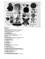
USER’S MANUAL
for M19Y / BLACK MAGIC
Distributed by: JPX ITALIA
Production Plant: Via Falcone 4, 42021 Barco di Bibbiano (RE) Italy
Phone:(39)0522-246544 Fax:(39) 0522-246169 www.jpxitalia.com
e-mail [email protected]
INTRODUCTION
Thank you for choosing our engine, the CORS-AIR M19. Please, spend some
time reading this manual, which will let you discover all the features of your
engine. Advices on maintenance and operation will help you to have a reliable
engine and to preserve your investment. We ask you to pass on the manual and
all relevant documentation should you sell the engine so it can be useful for the
next owner as well.
Should you have any questions about the engine, please contact your local
distributor who should be able to help you, a list of dealers can be found on our
website www.jpxitalia.com
YOUR SAFETY AND THE SAFETY OF THE PEOPLE AROUND YOU IS
VERY IMPORTANT TOUS.
IDENTIFICATION OF THE OWNER
Owner:..
Address:..
Serial number:..
Reseller:..
Address:..
Owner’s signature:..
Reseller’s signature and stamp:..
Date of sale:..
Dealers Seal:..
The Company reserves the right to make technical and aesthetic changes without notice in order to improve the quality of the
product.
TECHNICAL FEATURES
Engine
M19
Cycle
2 strokes
Total displacement
119,38 c.c.
Bore
57,5 mm.
Stroke
46 mm.
Weight
10 kg without exhaust
Complete exhaust
3,3 kg
Peak RPM
9400
Cooling
by free air
Piston
of light alloy with 2 piston rings of cast iron S10 cromium-plated
Cylinder
silicon light alloy with surfacing of Cermetal (NICASIL)
Head
special aluminium alloy
Crankcase
Cast alloy G-Al Si 9 UNI 3051
Carburettor
membrane
Feeding
reed valve on the crankcase
Electronic ignition
type TCI
Spark Plug
NGK B9ES
Starter
manual
Clutch
centrifugal
Reductor
with Poly V belt
Reduction
1:3,12
Continuous normal tempertaure
Max 250 °C
Exhaust pipe
tuned
Fuel
unleaded gasoline 98 octane and oil at 2,5%
Oil
Good quality fully synthetic 2 stroke oil mixed with the fuel at 40:1 (2.5%)
Engine suspension: Five rubber mounts (vibration insulators)
MAIN TORQUES
DECOMPRESSOR
Cylinder head nuts M8
Nuts fo fix half crankcase
Bolts to fix back support base to the crankcase
Ignition magnetic wheel (flywheel) nut
Gap between ignition coil and flywheel
Kg.m
(Nm)
1,9
19
2,2
22
2,5
25
2,0
20
3,5
35
min 0.35 mm, max 0.4 mm
ENGINE MOUNTING: The engine should be installed onto the frame using 4
rubber mounts of 40mm diameter on the flange by the recoil starter and a 5th
mount of 20mm diameter located on the underside of the engine next to the
clutch. The use of the 5th mount is imperative to prevent engine damage during
an eventual hard landing.
PROPELLER: The propeller must be attached using M8 10/8 bolts with a plain
shank. The bolt length must be of adequate length to ensure that the end of the
bolt protrudes all the way through the reduction pulley and it must have
sufficient length to ensure the prop can be tightened correctly without the bolts
thread locking. The prop bolts should be torqued to 15Nm. If the propeller
manufacturer specifies a different torque please, contact your dealer for further
advice. Prop overhang must be kept to a minimum, and as a consequence, the
use of props with separate hubs (such as ground adjustable props) is not
recommended. Altering the loading on the engine by changing the prop, or
adjusting the pitch can have affects on the fuel mixture. If a replacement prop is
installed, the prop diameter altered or the pitch is adjusted, it will be necessary
to carry out a check of the engine revs and re-adjust the carb mixture. THE
ENGINE MUST NEVER BE STARTED WITHOUT A SUITABLE PROP
INSTALLED.
FUEL SYSTEM: The fuel system must be designed to ensure adequate fuel
supply under all operating conditions. The engine demand may be as high as
8.5L/Hr and therefore the system must be capable of supplying at least 11L/Hr.
From our experience, the hose should have minimum bore size of 5mm, and any
fittings or filters must have a minimum bore of 4.5mm. A nylon or polyester
mesh fuel filter with a fine mesh of 0.15mm must be installed in the line. Max
total fuel line length is 800mm.
AIR FILTER: A suitable air filter/air-box that does not restrict the airflow to
the engine must be installed at all times.
INSTRUMENTS: All engines should have a suitable Cylinder Head
Temperature gauge fitted. We would also recommend installing an Exhaust Gas
Temperature gauge.
SECURITY: Mounting of the Air-box, exhaust system & air filter must be
considered by the frame designer. Safety cables must be installed by the frame
manufacturer to ensure that any parts that may come loose, can not enter the
prop. Wire locking of the exhaust springs & exhaust manifold nuts is essential.
FUEL: Use only fresh unleaded gasoline of minimum 98 Octane with a good
quality fully synthetic 2 stroke oil. Mix the oil at a ratio of one part oil to 40
parts fuel (2.5%) (250 ml of oil per 10 l fuel). Ensure the fuel/oil is fully mixed in
a separate container before filling up the fuel tank. Do not mix the fuel in the
paramotor fuel tank. Always use a device (ie. a funnel) with a filter to transfer
the fuel from the mixing can to the paramotor tank.
PRE-FLIGHT CHECKS: It is the operator’s responsibility to ensure the
serviceability of their engine prior to every flight. The following list is a guide of
items to check, but it the pilot’s responsibility to thoroughly check the entire
machine & engine prior to flight.
Inspect all wiring and connections.
Inspect engine for leaks.
Check that all fasteners are tight or torqued to the specs.
Ensure fuel system is free of leaks and the fuel filter is clean.
Check propeller is secure, and undamaged.
Ensure fuel tank vent is not blocked.
Thoroughly check the exhaust system for cracks (WARNING – HOT PARTS).
Check reduction drive belt condition & check tension (described further in this
manual)
Ensure that rubber mounts are in good condition and there are no signs of wear,
cracks or separation.
Remove plug cap, rotate engine and listen for unusual noises.
Check reduction pulley bearings for play.
Refit plug cap.
Ensure correct operation of the throttle cable & ensure the movement is free &
smooth.
Check contents of fuel tank, and security of cap.
Ensuring the area is clear of bystanders especially BEHIND and on the SIDES
of the propeller.
With the machine secure start the engine and warm the engine up below 2700
rpm until the CHT reaches 120C. Listen for unusual noises and abnormal
vibrations.
ADJUSTMENT OF THE CARBURETTOR
The carburettor has two mixture adjustment screws, one marked “L” for
adjusting low speed and one marked “H” for high speed.
In order to make the adjustment, gently tighten clockwise until fully seated then
unscrew:
” L “screw between 3/4 (three quarter) to one turn,” H” screw between 1 1/4
(one and a quarter) to 1 1/2 (one and a half) turn -adjustment with filter Air Box
(Kart model), we advise this kind of air-filter. These adjustments can be
different on the basis of weather conditions and flight altitudes. Ideal mixture is
reached when the insulator of the spark plug is coffee brown; if the colour
is black, the mixture is too rich, therefore turn screw H clockwise at 1/8
increments. If the spark plug is grey/white, the mixture is LEAN, therefore turn
screw H and L counterclockwise always 1/8 at a time. Remember that if the
mixture is too lean, THE PISTON CAN SEIZE or detonation may occur. A true
colour can be obtained by running the engine flat out for 20 seconds at high rpm
and then switching it off. Once you have found the perfect setting, do not change
it unless you change the flight location, or climate conditions.
RUNNING-IN FOR THE FIRST 20 HOURS:
All CORS-AIR engines, before being delivered, are subject to a severe check, in
order to ensure the highest possible quality.
A GOOD RUNNING-IN WILL PROLONG THE LIFE OF YOUR ENGINE.
Go to a quiet place, put a thick rubber carpet under your craft to avoid that
stones or other debris could damage the propeller.
Start the engine and let it work at 2500 rpm for 5 minutes, then accelerate speed
to 3000/3500 rpm for 15 minutes, then increase engine speed to 4000 rpm for
other 10 minutes. Ensure that the CHT does not exceed 250C during the
running in process. Switch off the engine and thoroughly inspect it, including
checking for leaks, loose fasteners, damage, cracks etc.
BE CAREFUL NOT TO TOUCH HOT PARTS (POWER UNIT AND
EXHAUST PIPE).
Start the engine again and take it step by step to 4000 rpm for 5 minutes, then
accelerate to 4500 rpm for 10 minutes. During the first 10 hours, the engine
should be used conservatively and not subjected to excessive high power settings.
High loads and prolonged high power settings will reduce the engine life & will
increase the risk of failure.
ATTENTION: this engine is free air cooled. The airflow generated by the
propeller (and your airspeed in flight) are essential for the correct cooling of the
engine.
To obtain the best cooling, the cylinder on all Cors-Air engines is tilted to the
side so the airflow will not be obstructed by the pilot’s back. Please, make sure
that NO objects will restrict this flow (mount the reserve parachute overhead or
on the opposite side of the cylinder).
MAINTENANCE:
After the first 1 hour running in (before flight):
Carry out pre-flight inspection as detailed on page 5
Re-torque the propeller fasteners
Re-torque the exhaust nuts
Re-torque the cylinder head nuts
Re-torque the spark plug
Adjust the belt tension
Every 20 hours:
Check and clean the spark plug. Gap (0.7 mm)
Clean the air-filter
Replace the fuel filters
Check the torque of every bolt
Tighten head nuts (in cross order) with a torque wrench to 2.2 Kg.m
(22Nm)
Check the tension and condition of the reduction belt
Check fuel lines and their connections
Check the wiring
Grease the exhaust ball joint with copper-grease suitable for high
temperature
Check the springs between the manifold and the exhaust
Balance the propeller!!!
Every 50 hours:
Carry out the 20 Hr checks plus the following:
Check the torque of the engine’s crankcase nuts
Replace the spark plug
Change the petals of the reed valve
Check the reduction belt and the play in the bearings of the reduction
pulley; replace if necessary
Once a year (independently from flight hours and as preventive
maintenance) change the
diaphragm of the carburetor to avoid
carburetor problems
Every 150hrs:
Carry out the 50Hr Checks plus the following:
Remove the exhaust, cylinder head, cylinder & piston.
Check the cylinder & piston.
Inspect the piston pin & piston pin bearing.
De-carbonize the engine
Rebuild the engine with new gaskets.
Nota Bene: It is advisable to keep records of all maintenance in a log book for
the engine.
TENSIONING OF THE REDUCTION BELT DRIVE - USE CAUTION!!!
The belt tension will have to be adjusted during the first few hours of operation,
and after each replacement. Care needs to be taken to ensure the correct
adjustment as over tightening will cause damage to the reduction pulley
bearings, shaft and possibly the crankshaft bearings.
Before adjusting the belt take a marker and make a small line on the eccentric
shaft of the big reduction pulley and on the front of the reduction plate. This is
your Zero or starting point and from here, you will be able to clearly see how
much you move the eccentric shaft of the big reduction pulley tensioning the belt
in relation to the reduction plate. Remember “these are Fine adjustments” and
we suggest not to rotate the shaft any more than 1 mm per adjustment. After
each adjustment you can try to start the engine and check the result. The Belt
tension ALWAYS increases automatically when the engine is running because of
thermal expansion in the pulleys and crankcase. Once you have found the
correct tension , do not adjust it any more. In case of doubts please contact your
paramotor dealer – or JPX Italia.
To adjust the belt, do the following:
Loosen the safety bolt located high up behind the reduction mounting plate and
the side bolt. Once these are loosened then you can turn the shaft with a 27 mm
size wrench - carefully, to observe the 1 mm increments. Once you have finished
turning the cam remember to re-tighten the safety bolts, first the back bolt, by
keeping firm the cam with the wrench, and then the side bolt.
Note: in order to get the correct results, it is imperative that the belt and pulleys
are clean (free of black deposits in the grooves) and free of oil
IGNITION:
Should it be necessary to replace the coil or flywheel your engine will need to be
returned to your dealer or an engineer with suitable training to carry out the
work.
The operation is not as simple as it would first appear. Incorrect fitting of the
coil will alter the ignition timing and may cause permanent damage to your
engine. The distance between the coil and the flywheel magnet is 0,40 mm.
LONG TERM STORAGE OF THE ENGINE
If you intend to store your engine for more than 3 months without use, carry out
the following:
Drain the fuel tank, including the fuel lines and the carburetor.
Unscrew the spark plug and pour a teaspoon of 5ml of synthetic 2 stroke engine
oil in the hole. Then re-install the spark plug letting the propeller turn slowly by
hand for 2 or 3 complete turns.
Disassemble the propeller, cover it and store it in a horizontal position.
Loosen the reduction belt.
Plug the hole of the exhaust pipe to prevent access of moisture.
Cover everything with a blanket and put it in a dry place.
Once a month turn the engine over by hand 2 or 3 times completely.
BRINGING THE ENGINE OUT OF STORAGE:
Prior to bringing an engine back into operation that has been stored for more
than 6 months, a 50 Hr service should be carried out. Great care needs to be
taken in inspecting all components for corrosion.
WARRANTY:
All CORS-AIR engines are manufactured with top-quality material and
technology, therefore warranty is valid also for their accessories.
DURATION OF WARRANTY:
1 YEAR beginning from the date of sell or exit from the JPX ITALIA
Warranty includes spare parts and labour, transport costs are the responsibility
of the end user.
WARRANTY IS VOID IN THE FOLLOWING SITUATIONS
Alterations to the engine not approved by JPX Italia.
Normal Wear & tear of components
Accidental falls or dropping of the engine or its components
Overheating or seizure of the engine due to prolonged high speed running of the
engine, incorrect setting of carburetor or insufficient lubrication by using low
quality two stroke oil or inappropriate gas/oil mixtures.
Running with excessive loads,
Running with inadequate loads (running engine without propeller or propeller
with too small pitch thus exceeding the max. RPM)
Running with insufficient oil in the gasoline
Incorrect tuning of the carburetor or running with no oil in gas
The presence of dirt, sand or foreign bodies in the carburetor or the engine.
Corrosion through poor storage of the engine or inadequate preparation for
storage
Running the engine without an air-filter fitted to the carburetor.
Miss-assembly of engine parts or components not assembled by JPX Italia but
by the paramotor manufacturer or by the end user, supplied disassembled for
packing and transport purposes.
Corrosion of the engine or components emanating from stone chips or any other
impact or abnormal stress damage.
Work other than standard maintenance set out in the product manual having
been carried out on the engine by anyone other than JPX Italia or its official
dealers.
Incidental or consequential loss or damage.
Service bulletins from JPX Italia not having been adhered to.
Engine used for competitions.
Please, contact JPX ITALIA or one of their dealers if there is anything
contained in this manual that is unclear, or if you need any further information.
TROUBLESHOOTING
THE ENGINE DOES NOT START
Check:
On-off switch
Cable of the spark plug
Correct spark plug gap
All electrical connections
Fuel supply to the carb
Check the tension of the reduction belt drive
FLOODED ENGINE
Remove the spark plug and dry it well ; before re-fitting it, pull the engine over
several times ensuring the ignition switch is in the OFF position.
THE ENGINE DOES NOT HOLD IDLE SPEED OR HAS AN IRREGULAR
SPEED:
Clean and adjust the carburetor. Check the reed valve petals for damage and
ensure they are fully closed. Hold the reed up to a light and you should not see
any light past the petal seating area.
THE ENGINE CANNOT REACH MAXIMUM SPEED
Check if the throttle is opening fully.
Check that there is no dirt in the carburetor filter and there are no restrictions
or air bubbles in the fuel line.
Check all fuel hose connections are secure.
Check the spark plug: if it is worn or has carbon build-up replace it. Check the
gap and remember to replace the plug with the correct plug type & heat range.
Check the connection between the high voltage cable and the spark plug cap;
tighten the cap on this wire. If the connection is not tight, arcing may occur and
this will affect the strength of the spark giving accelerating problems at low or
max RPM and very hard starts.
THE DECOMPRESSOR REMAINS BLOCKED:
The most common symptom is a constantly worsening start. If you notice that in
time you need more pulls in order to start the engine and/or you hear popping
noises in the exhaust but the engine fails to start this may point (besides a reed
valve, carburetor or electrical problem) to a partially stuck decompressor.
Remove the decompressor & clean away any carbon deposits. Lubricate the
stem with WD-40 or similar light lubricant. Reinstall decompressor torquing it
to 20NM (2.0 Kg Meters) MAX.
Do not overtorque because you will damage the threads in the cylinder.
Before installation, on the threads of the decompressor, apply a thin coat of
antiseize or Permatex non-hardening, high temperature gasket and flange
sealant
IF THE CLUTCH DOES NOT WORK SMOOTHLY
Put 2-3 drops of oil inside the clutch bell.
SOME FINAL ADVICE:
NEVER switch on the engine with people near propeller, or to sides. The
BREAKAGE of a propeller can cause very severe injuries even from several
meters away.
DO NOT keep engine at peak rpm after the take off, except when absolutely
necessary (clearing obstacles)
If you use big propellers, REMEMBER that cooling is less effective and it is the
pilot’s responsibility to keep the engine temperature within limits (CHT gauge
required)
In addition, dismantle the propeller at regular intervals and check that it is
perfectly balanced. A propeller that is even slightly out of balance creates microvibrations which even if not felt by the pilot, can cause serious damages to the
engine and to the frame. Since the propeller has mass and a considerable inertial
momentum, blipping the throttle is not recommended as it can cause all sorts of
problems with the reduction drive system and crankshaft.
Again, so it’s advisable not to vary suddenly the RPM of the engine, both in
flight and on the ground. These sharp and violent stresses could cause damages
to the reduction drive, the engine’s different other components.
Once you have found the perfect carburation, DO NOT modify it unless there
are significant changes in the climate, altitude, temperature or you change your
propeller.
Please visit the www.aerocorsair.com web site which on The Inventions Page,
has many useful articles about maintenance and repairs of the Cors-Air engines.
We wish you many happy flights with your newly purchased engine!
The Cors-Air Team
1) CRANKCASE
2) HEAD
3) CYLINDER
4) PISTON COMPLETE OF PISTON-PIN AND LOCK
5) PISTON RINGS (N° 2 pcs. together with the piston)
6) BEARING OF DRIVE SHAFT (n° Pcs. 2)
7) CYLINDER GASKET
8) DECOMPRESSOR
9) COVER OF THE CRANKCASE
10) TIE-ROD FOR HALF CRANCKASE
(n° Pcs.4)
11) TIE-ROD HEAD/CYLINDER (n° Pcs. 4)
12) BELT
13) HEAD GASKET
14) CRANKSHAFT COMPLETE OF CONNECTING ROD
15) CRANKSHAFT OIL SEALS
(n° Pcs. 2)
16) NEEDLE BEARING
17) BACK SUPPORT BASE
18) STARTER
19) STARTER BASKET
20) FLYWHEEL
21) IGNITION COIL
22) REED VALVE
23) FLANGE FOR CARBURETTOR BED
24) CARBURETOR
25) AIR FILTER FLANGE
26) BIG REDUCTION PULLEY
27) BIG REDUCTION PULLEY ECCENTRIC SHAFT
28) CLUTCH BELL WITH SMALL REDUCTION PULLEY
29) BEARING OF REDUCTION PULLEY
(n° Pcs. 2)
30) CLUTCH ASSEMBLY
31) BEARINGS OF CLUTCH BELL
32) CLUTCH SAFETY CLIP
33) NUT FIXING THE CLUTCH GROUP
34) SPACERS FOR BEARINGS OF THE CLUTCH BELL