1
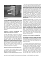
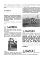
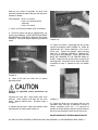
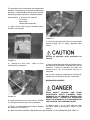
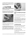
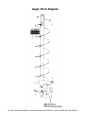
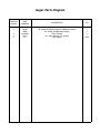
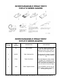
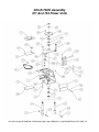
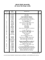
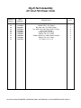
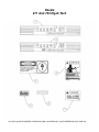
OPERATOR MANUAL
Includes Safety, Service and Replacement Part Information
Model 671 and 753 Series
Hydraulic Hole Digger
Form: GOM-1028-7-88
Version 1.0
Do not discard this manual. Before operation, read and
comprehend its contents. Keep it readily available for reference
during operation or when performing any service related
function. When ordering replacement parts, please supply the
following information: model number, serial number and part
number. For customer service assistance, telephone
800.533.0524, +507.451.5510. Our Customer Service Department
telefax number is 877.344.4375 (DIGGER 5), +507.451.5511.
There is no charge for customer service activities .
Internet address: http://www.generalequip.com.
E-Mail location: [email protected].
Copyright 2003, General Equipment Company.
Manufacturers of light construction
equipment
Congratulations on your decision to purchase a General light construction product. From our
humble beginnings in 1955, it has been a continuing objective of General Equipment Company to
manufacture equipment that delivers uncompromising value, service life and investment return.
Because of this continuous commitment for excellence, many products bearing the General name
actually set the standards by which competitive products are judged.
When you purchased this product, you also gained access to a team of dedicated and
knowledgeable support personnel that stand willing and ready to provide field support
assistance. Our team of sales representatives and inhouse factory personnel are available to
ensure that each General product delivers the intended performance, value and investment return.
Our personnel can readily answer your concerns or questions regarding proper applications,
service requirements and warranty related problems.
General Equipment Company places great emphasis upon not only product performance, but also
on product safety. It is important to remember that this product will only be as safe as the operators
which utilize it. It just makes good, common sense to take the time to read and fully understand the
contents of this manual before attempting to utilize this product in service. If you ever do have any
questions or concerns about this product, please feel free to contact our Customer Service
Department at the telephone numbers listed below for assistance.
If there is anything that I can do to assist your efforts when utilizing this product, please do not
hesitate to contact me. For assistance after normal business hours, telephone me at 507.451.9409
or 507.363.1033. If I am not immediately available, I will attempt to return your call as soon as
possible.
Sincerely,
GENERAL EQUIPMENT COMPANY
Dennis Von Ruden
President
620 Alexander Drive SW • P.O. Box 334 • Owatonna, Minnesota 55060-0334 USA
Telephone: 800.533.0524 • International Telephone: +507.451.5510
Telefax: +507.451.5511 • Sales/Customer Service Department Toll Free: 877.344.4375 (DIGGER 5)
http://www.generalequip.com • e-mail: [email protected]
Table of Contents
DESCRIPTION
PAGE
Notice to Operators
3
Operator Instructional Data Sheet
5
Safety Precautoins
6
Operation
MAINTENANCE, REPAIR AND STORAGE
HYDRAULIC SYSTEM INFORMATION
7
8
9
Installation
DIGGING OPERATION.
AUGER EXTENSIONS.
12
14
16
Service
CHAIN MAINTENANCE.
BEARING MAINTENANCE.
BEARING REPLACEMENT.
17
17
18
19
Trouble Shooting
20
Storage
20
Specificaiotns
20
Parts Breakdown
21
671 AND 753 HOLE DIGGERS, FORM GOM-1028-7-88, VERSION 1.0, AUTHORIZATION: DVR, PAGE: 2
Notice to Operators
IF YOU CAN NOT READ OR DO NOT FULLY UNDERSTAND THE CONTENTS OF THIS
MANUAL, PLEASE CONTACT THE FACTORY FOR PROPER ASSISTANCE BEFORE
ATTEMPTING TO OPERATE THIS PRODUCT.
SI TU NO PUEDES LE'ER O NO COMPRENDES EL CONTENIDO DE ESTE MANUAL
FAVOR DE PONERSE EN CONTACTO CON LA. FABRICA PARA ASSISTENCIA- A
PROPIA ANTES DE INTENTAR PARA OPERAR ESTE PRODUCTO.
SOLLTEN SIE DIESE GEBRAUCHSANWEISUNG NICHT LESEN KOENNEN ODER ES
NICHT VOLLKOMMEN VERSTEHEN, WENDEN SIE SICH BITTE AN DEN HERSTELLER
FUER RICHTIGE HILFE EHE SIE VERSUCHEN DIESES PRODUKT ZU OPERIEREN.
SI VOUS NE LISEZ OU NE COMPRENDRE ENTIEREMENT LES MATIERES DE CE
MANUEL, S'IL VOUS PLAIT, CONTACTEZ L'USINE POUR L'ASSISTANCE
APPROPRIEE AVANT D'UTILISER LE PRODUIT.
These safety alert symbols identify important safety messages in this manual. When you see these symbols,
be alert to the possibility of personal injury and carefully read the message that follows.
Do not allow anyone to operate the Hole Digger without first reading this Operator's Manual and becoming
familiar with its operation. The manufacturer of this Hole Digger has gone to great extremes to provide the
owner(s) and/or operator(s) with the finest equipment available for its intended job function of digging holes
in ice and earth formations. Yet, the possibility exists that the Hole Digger can be utilized in and/or subjected
to job applications not perceived and/or anticipated by the manufacturer. Such misuse and/or misapplication
of the Hole Digger can lead to the possibility of serious damage, injury or even death. It is the responsibility
of the owner(s) and/or operator(s) to determine that the Hole Digger is being utilized and/or operated within
the scope of its intended job function. It is the responsibility of the owner(s) and/or operator(s) to establish,
monitor and constantly upgrade all safety programs and/or practices utilized in and for the operation of the
Hole Digger. The purpose of such programs is to provide for owner(s') and/or operator(s') safety. Operators
must be instructed to recognize and avoid unsafe conditions associated with their work (29 CFR 1926.21
(b)(2)) and/or applicable updated revisions. It is the responsibility of the owner(s) and/or operator(s) to
determine that no modifications and/or alterations have been made to the Hole Digger. Modifications and/or
alterations can lead to the possibility of serious damage, injury or even death. It is the responsibility of the
owner(s) and/or operator(s) to make this Operator's Manual available for consultation during all phases of
operation. Refer to OSHA 2207 which contains all OSHA job safety and health rules and regulations (1926
and 1910) covering construction.
The concept of portable, one and two man operated, hole digging equipment has been successfully utilized
for over forty years as a practical solution to many types of hole digging job requirements. The basic concept
is proven and well accepted within the associated marketplaces as an alternative method to manual labor
and/or larger, mounted earth drilling machinery. Use of a Hole Digger requires strenuous work activity. This
type of work activity can be considered to be greater in magnitude than that experienced with the use of
many other types of both light construction and lawn and garden related equipment. This type of work
activity should only be attempted by operators of adequate physical size and stature, mental awarness and
671 AND 753 HOLE DIGGERS, FORM GOM-1028-7-88, VERSION 1.0, AUTHORIZATION: DVR, PAGE: 3
physical strength and condition. Each operator is required to supply a resultant force that
counteracts/balances and/or resists the natural torque and kickback forces generated during the hole
digging process. The body parts most noticably affected during the digging process are the arms, hands,
wrists, shoulders, lower back and legs. The hole digging process can also produce excessive stress/strain
directly to the back muscles, spinal vertabrae and many other body parts. Back related pain can be a side
effect of the hole digging process. An operator with a chronic back related problem or a history of back
and/or other medically related problems should not attempt to utilize the Hole Digger. Use of the Hole Digger
may only aggrevate this and any other medically related problem. The torque and kickback forces generated
and/or encountered correspond to the natural laws of physics and are inherent to the hole digging process.
They can not be changed or totally eliminated with portable one and two man operated, hole digging
equipment of this design. Proper operating positions and techniques, as outlined in this manual, can be
successfully utilized to minimize the effects of the torque and kickback forces upon the human body.
Because of the diverse type of prevailing digging conditions, operator experience levels and operator
physical characteristics, no warranty, guarantee, representation and/or liability is made by the factory as to
the absolute correctness or sufficiency of any operational procedure, operational position and/or technique.
There is no absolute guarantee that an operator of any given experience level, physical size and/or physical
condition will be immune to the possibility of and/or probable physical side effects of the normal hole digging
process. The normal hole digging process includes the auger striking buried obstructions (roots, rocks, etc.)
and the resulting torque and kickback forces created. Each potential operator of the Hole Digger must be
made aware of and assume the operational and physical liability described and/or associated with the hole
digging process when utilizing the Hole Digger. Each potential operator not willing to assume the operational
and physical liability described and/or associated with the hole digging process should not operate the Hole
Digger. Proper levels of operator experience, skill and common sense are essential for maximizing the safe
and efficient operation of the Hole Digger.
Record the Hole Digger and engine serial numbers in the spaces provided below.
_______________ Model Number
_______________ Serial Number
_______________ Engine Serial Number
_______________ Date of Purchase
Specifications and design are subject to change without notice or obligation. All specifications are general
in nature and are not intended for specific application purposes. General Equipment Company reserves the
right to make changes in design, engineering or specifications and to add improvements or discontinue
manufacture at any time without notice or obligation. General Equipment Company and its agents accept no
responsibility for variations which may be evident in actual products, specifications, pictures and
descriptions contained in this publication.
Operator Instructional Data Sheet
671 AND 753 HOLE DIGGERS, FORM GOM-1028-7-88, VERSION 1.0, AUTHORIZATION: DVR, PAGE: 4
The following undersigned operators of the Hole Digger described and/or pertaining to this Operator's
Manual have received formal safety and operational information/instruction from the undersigned
owner(s)/instructor(s) in accordance to OSHA 29 CFR 1926.21 (b)(2) and/or applicable updated revisions
pertaining to, but not necessarily limited to the:
1) READING, COMPREHENSION AND ACKNOWLEDGEMENT OF THE MATERIAL COMPRISING THE
ENTIRE CONTENTS OF THE APPLICABLE OPERATOR'S MANUAL FOR THE HOLE DIGGER.
2) FORMALIZED OPERATOR'S SAFTEY PROGRAM TO BE DEVISED BY THE OWNER OF THE HOLE
DIGGER IN CONJUNCTION WITH THE CONTENTS OF THE APPLICABLE OPERATOR'S MANUAL FOR
THE HOLE DIGGER.
3) OSHA RULES AND REGULATIONS RESEARCHED FOR AND/OR BY THE OWNER OF THE HOLE
DIGGER AND DEEMED APPLICABLE TO THE SAFE AND PROPER USE AND/OR OPERATION OF THE
THE HOLE DIGGER FOR ANY SPECIFIC JOB APPLICATION.
4) LOCAL LAWS, REGULATIONS AND CUSTOMS RESEARCHED FOR AND/OR BY THE OWNER OF
THE HOLE DIGGER AND DEEMED APPLICABLE TO THE SAFE AND PROPER USE AND/OR
OPERATION OF THE HOLE DIGGER FOR ANY SPECIFIC JOB APPLICATION.
5) FORMALIZED MAINTENANCE PROGRAM FOR THE HOLE DIGGER TO BE DEVISED BY THE
OWNER OF THE HOLE DIGGER IN ACCORDANCE WITH, BUT NOT NECESSARILY LIMITED TO, THE
SPECIFICATIONS, GUIDELINES AND OPERATIONAL INFORMATION CONTAINED IN THE
APPLICABLE OPERATOR'S MANUAL.
6) COMPREHENSIVE OPERATIONAL INSTRUCTIONS FOR THE CORRECT AND PROPER USE OF THE
HOLE DIGGER AS PER THE CONTENTS OF THE APPLICABLE OPERATOR'S MANUAL.
_______________ Operator
_______________ Owner/Instructor
__________ Date
_______________ Operator
_______________ Owner/Instructor
__________ Date
_______________ Operator
_______________ Owner/Instructor
__________ Date
_______________ Operator
_______________ Owner/Instructor
__________ Date
_______________ Operator
_______________ Owner/Instructor
__________ Date
_______________ Operator
_______________ Owner/Instructor
__________ Date
NOTE: INSERT COPIES OF THIS PAGE WITHIN THE OPERATOR'S MANUAL IF SPACE FOR
ADDITIONAL OPERATORS IS REQUIRED.
671 AND 753 HOLE DIGGERS, FORM GOM-1028-7-88, VERSION 1.0, AUTHORIZATION: DVR, PAGE: 5
Safety Precautions
THE 671 DIG-R-TACH IS NOT DESIGNED TO
DRIVE/INSTALL ANCHORING DEVICES OF ANY
TYPE, DESIGN OR STYLE. THE AUGERS AND
AUGER EXTENSIONS ARE NOT TO BE UTILIZED
AS
ANCHORING
DEVICES
IN
ANY
CONFIGURATION.
WHILE THERE MAY BE
VARIOUS DESIGN SIMILARITIES BETWEEN
AUGERS AND ANCHORING DEVICES, THE TWO
PRODUCTS ARE DESIGNED FOR DISTINCTLY
DIFFERENT JOB APPLICATIONS. IMPROPER JOB
APPLICATIONS FOR BOTH PRODUCTS WILL
RESULT IN PROPERTY DAMAGE, PERSONAL
INJURY OR EVEN DEATH.
THE FOLLOWING SAFETY PRECAUTIONS
PROVIDE SOME COMMON SENSE GUIDES TO
PROMOTE SAFETY AND EFFICIENCY WITH THE
671 DIG-R-TACH. NO WARRANTY, GUARANTEE
OR REPRESENTATION IS MADE BY THE FACTORY
AS TO THE ABSOLUTE CORRECTNESS OR
SUFFICIENCY OF ANY INFORMATION OR
STATEMENT. THESE SFETY PRECAUTIONS ARE
INTENDED TO DEAL PRINCIPALLY WITH THE
COMMON
PRACTICES
AND
CONDITIONS
ENCOUNTERED IN THE 671 DIG-R-TACH AND ARE
NOT INTENDED TO BE ALL INCLUSIVE. PROPER
LEVELS OF OPERATOR EXPERIENCE, SKILL AND
COMMON SENSE ARE ESSENTIAL FOR SAFE
AND EFFICIENT OPERATION.
INCORRECT USE OF THE 671 DIG-R-TACH CAN
RESULT IN PROPERTY DAMAGE, PERSONAL
INJURY OR EVEN DEATH, TO REDUCE THIS
POSSIBILITY, GIVE COMPLETE AND UNDIVIDED
ATTENTION TO THE JOB AT HAND AND FOLLOW
THESE SAFETY PRECAUTIONS:
PREPARATION.
1) This M671 DIG-R-TACH is a specialized type of
powered equipment, designed for a specific job
function and requires adequate and thorough
instruction BEFORE it is operated. The size, power
system, complexity and operating characteristics of
this type of powered equipment would dictate that each
operator must receive adequate, professional
instruction regarding the proper operation of this M671
DIG-R-TACH before being allowed to utilize it.
BEFORE attempting to utilize the M671 DIG-R-TACH,
read this Operator’s Manual and the material supplied
by the power source manufacturer to familiarize each
operator with its correct operating procedures. When
you are going to dig holes-DO IT RIGHT- avoid the
urge not to take the necessary time to read this
Operator’s Manual before utilizing the M671 DIG-RTACH. DO NOT OPERATE THIS M671 DIG-R-TACH
UNTIL
EACH
OPERATOR
COMPLETELY
COMPREHENDS THE CONTENTS OF THIS
MANUAL.
2) Develop a comprehensive program for the safe
operation of the M671 DIG-R-TACH by its owner(s)
and/or operator(s). Such a program will include, but is
not limited to: instructional requirements for operation,
applicable OSHA requirements, local laws and
regulations, job site safety and a M671 DIG-R-TACH
maintenance program. Constantly examine and
upgrade this program to guarantee owner(s) and/or
operator(s) safety. Each operator must be fully
instructed regarding the specifics of this safety
program.
3) Determine that the M671 DIG-R-TACH is in its
original, factory configuration and has not been
modified in any manner. Determine that hoses and
connectors are in good mechanical condition. Many
modifications can result in potentially dangerous
configurations that can lead to property damage and/or
personal injury. If there are any questions about
possible modifications made to the M671 DIG-RTACH, contact the Customer Service Department for
specific information BEFORE utilization. There is no
charge for this service.
4) Minors should never be allowed to operate the
M671 DIG-R-TACH. Bystanders, especially children
and animals should not be allowed in the area where a
M671 DIG-R-TACH is in use.
5) Operators must be in adequate physical condition,
mental health and not under the influence of any
671 AND 753 HOLE DIGGERS, FORM GOM-1028-7-88, VERSION 1.0, AUTHORIZATION: DVR, PAGE: 6
substance (drugs, alcohol, etc.) which might impair
vision, dexterity or judgment. Installation and/or
working with the M671 DIG-R-TACH is strenuous. If
you have any condition that might be aggravated by
strenuous work, check with your doctor before
operating the M671 DIG-R-TACH. Guard against the
possibility of back related injuries.
6) Contact appropriate representatives to determine
where buried electrical cable, gas lines and other
hazardous items are buried. The M5671 DIG-R-TACH
is not insulated. Contact with buried electrical cable or
gas lines can result in electrocution and/or explosion.
Determine that any overhead power/utility lines over
the job site will not come in contact with the power
source boom structure and/or the DIG-R-TACH/Auger.
7) Clothing must be sturdy and snug fitting, but allow
complete freedom of movement. Never wear loose
fitting jackets, scarves, neckties, jewelry, flared or
cuffed pants or anything that could become caught on
controls or moving parts. Wear long pants to protect
your legs. Protect your hands with heavy duty, nonslip
gloves to improve your grip. Good footing is most
important when operating the M671 DIG-R-TACH.
Wear sturdy boots with nonslip soles. Steel-toed safety
boots are highly recommended. Never wear tennis
shoes or other similar type shoes which afford little or
no protection. Wear an approved safety hard hat to
protect the operator(s’) head(s) where there is a
danger of head injuries. Noise, generated by the
engine of the Power Source, can damage your hearing.
Wear sound barriers (ear plugs or ear mufflers) to
protect your hearing.
Continuous and regular
operators should have their hearing checked regularly.
accessory attachment designed to be utilized by a wide
range of power sources it can be subject to a number
of operating limitations. As with any accessory
attachment, it can be limited to the number of practical
and/or suitable job applications for this type of
equipment. A particular job site, job specifications and
operator experience/skill/common sense may dictate
that a different type of power source and/or process be
utilized to properly complete the job with the degree of
efficiency and safety required. Contact the Customer
Service Department for specific information regarding
suitable power source vehicles, job applications, job
sites, and operator experience/skill/common sense
recommendations for M671 DIG-R-TACH BEFORE
utilization. There is no charge for this service.
11) Never exceed the recommended auger capacity of
the
M671
DIG-R-TACH.
Refer
to
the
SPECIFICATIONS section of this manual for more
detailed information. Always utilize the correct auger
and auger extension series for the M671 DIG-R-TACH.
OPERATION.
1) Give complete and undivided attention to the job at
hand. Help prevent the cause of an accident. Plan to
take work breaks as required to help insure proper
mental and physical alertness.
2) Before dismounting a skid steer loader, lower the
power unit/auger so that the auger lies edgeways on
the ground. Stop the engine. Cycle the auxiliary
hydraulic circuit control. Engage the parking brake.
Exercise caution while dismounting, FIGURE 1.
8) Visually inspect the M671 DIG-R-TACH, auger(s)
and auger extension(s) for damaged or worn parts.
Inspect each auger for proper screw bit and
teeth/blade. Check for loose and/or broken parts.
Determine that operator controls on power source work
freely, all safety devices are operative and information
decals are readable. Check to see that the M671 DIGR-TACH and all related accessories are in good
mechanical condition BEFORE utilization.
9) Know how the controls of the power source operate.
Be fully aware of its rules for safe operation, specific
operating characteristics and/or limitations. Use of a
M671 DIG-R-TACH with any specific power source can
affect the power source operating characteristics
FIGURE 1
and/or limitations. Be aware of these possible changes
to its operating characteristics and/or limitations. Know
how to stop the engine quickly in an emergency.
3) Operate the M671 DIG-R-TACH only where the
10) Because the M671 DIG-R-TACH is classified as an
671 AND 753 HOLE DIGGERS, FORM GOM-1028-7-88, VERSION 1.0, AUTHORIZATION: DVR, PAGE: 7
power source has sure footing and stability. Be extra
careful of footing and stability on slopes.
4) Do not operate the M671 DIG-R-TACH in closed
areas where carbon monoxide fumes can accumulate.
5) Follow all manufacturer’s safety placards and
regulations for the power source.
6) Do not operate the M671 DIG-R-TACH with
onlookers close by. Caution all onlookers to stand clear.
Keep all body parts, loose clothing and foreign objects
clear of the rotating auger. Do not utilize a shovel
and/or foreign object to remove the loose soil from a
hole area while the M671 DIG-R-TACH is in use. Such
a practice can cause the shovel and/or foreign object to
become entrapped by the rotating auger, leading to the
possibility of property damage and/or personal injury.
7) Start and operate the M671 DIG-R-TACH only in a
well ventilated, outdoor area. Operate the M671 DIGR-TACH only when/where visibility and light are
adequate for the job at hand. Work carefully. Never
leave the M671 DIG-R-TACH running unattended.
a M671 DIG-R-TACH with damaged hoses and
connector assemblies. Replace any questionable part
or assembly with a genuine, approved replacement
part. Do not forsake proper maintenance for the price
of a few replacement parts. Proper maintenance does
not cost – it actually pays dividends. Do not attempt
any maintenance or repair work not described in the
Operator’s Manual. Have such work performed at your
dealer’s servicing shop.
5) Replace the auger teeth/blade and screw bit when
signs of excessive wear are seen. When such parts
are not replaced at proper intervals, undo wear will
occur at the boring head and auger flighting. The end
result is an inverted cone configuration for the auger,
which usually requires complete replacement, FIGURE
2. Digging with equipment that is past its useful service
life and/or has not been properly maintained can cause
property damage and/or personal injury. Auger service
life can be greatly extended with constant auger wear
part maintenance.
8) Stop the engine between each hole to minimize the
potential of personal injury. Special care must be
exercised in slippery conditions and in difficult,
overgrown terrain. Watch for hidden obstacles such as
tree stumps, roots and ditches. Keep proper footing
and balance at all times. The normal use of this tool is
on level ground. Other digging terrains can be
dangerous and should be avoided.
Only properly
trained operators should attempt these techniques.
MAINTENANCE, REPAIR AND STORAGE.
1) Use only genuine, approved replacement parts for
maintenance and repair. Use of parts manufactured by
others can result in property damage and/or personal
injury.
2) Follow the SERVICE instructions as outlined in the
appropriate section of the Operator’s Manual.
3) Always stop the engine and lower the M671 DIG-RTCH to the ground BEFORE checking or working on
the M671 DIG-R-TACH.
FIGURE 2
6) Utilize only the factory supplied auger bolt for
connecting the auger and auger extension to the M671
DIG-R-TACH. Use of any other connecting device,
including cap screws, bolts, pins, etc., can result in
damage to the M671 DIG-R-TACH driveshaft and/or
auger drive hub, FIGURE 3. Improper connecting
devices can cause property damage and/or personal
injury.
4) Always properly maintain the M671 DIG-R-TACH.
Frequently check all fasteners and individual parts.
Built in safety features are effective only if they are
maintained in good working condition. Do not operate
671 AND 753 HOLE DIGGERS, FORM GOM-1028-7-88, VERSION 1.0, AUTHORIZATION: DVR, PAGE: 8
– This value, usually measured in pounds per square
inch (PSI) or kilograms per square centimeter (kg/cm2),
is the amount of pressure that the hydraulic pump can
produce before the system relief valve opens and
bypasses the oil flow back to the reservoir. The relief
valve is normally installed in a control valve to control
the maximum pressure of a complete hydraulic circuit.
The hydraulic system pressure relief setting translates
into digging torque for the M671 DIG-R-TACH. THE
HIGHER THE PRESSURE RELIEF VALVE SETTING,
THE GREATER THE AMOUNT OF DIGGING
TORQUE THE M671 DIG-R-TACH WILL PRODUCE.
The limiting factor for digging torque is the maximum
allowable system pressure for the hydraulic motor of
the DIG-R-TACH. This value will differ for each Series
of DIG-R-TACH.
FIGURE 3
7) Before operating the M671 DIG-R-TACH, consult
your local OSHA office for information relative to its
safe operation. It is the responsibility of the owner(s)
and/or operator(s) to determine that the M671 DIG-RTACH and power source are operated in accordance
with all applicable Federal, State, Industry, and Local
laws and regulations. If you have any questions about
the operation or about suitable applications for the
M671 DIG-R TACH, please contact the Customer
Service Department BEFORE proceeding to use this
equipment.
HYDRAULIC
SYSTEM
PARAMETERS
OPERATION OF THE M671 DIG-R-TACH.
FOR
The M671 DIG-R-TACH is designed to be operated
from the auxiliary hydraulic systems of mobile power
sources including, but not limited to: skid steer loaders,
tractor loader backhoes, industrial tractors, excavators
and all-terrain forklifts. Like any other hydraulically
operated attachment, the M671 DIG-R-TACH is
dependent upon the operating parameters of the given
auxiliary hydraulic system of the power source for both
performance and service life. A M671 DIG-R-TACH
that is operated by an auxiliary hydraulic system that
does not meet the specific operating parameters as
defined by this manual, will result in less than
satisfactory performance and service life.
AUXILIARY HYDRAULIC SYSTEM TERMINOLOGY.
It is essential, when outlining hydraulic system
requirements, to define the parameters that affect the
operation of the M671 DIG-R-TACH.
HYDRAULIC SYSTEM PRESSURE RELIEF SETTING
HYDRAULIC SYSTEM FLOW – This value, usually
measured in gallons per minute (GPM) or liters per
minute (lit/min), is the amount of oil flow that the
hydraulic pump can produce at a given engine speed
of the power source. The hydraulic system flow value
translates into auger RPM for the M671 DIG-R-TACH.
THE HIGHER THE HYDRAULIC SYSTEM FLOW, THE
FASTER THE AUGER WILL ROTATE. The limiting
factor for auger RPM is the maximum allowable
hydraulic flow for the hydraulic motor of the DIG-RTACH. This value will differ for each Series or DIG-RTACH. Another limited factor is the diameter of the
auger being utilized. The rotational speed (in feet per
minute) of the outside auger tooth must be kept within
industry recognized standards to maximize digging
efficiency and minimize wear.
HYDRAULIC MOTOR OPERATING PARAMETERS.
The TRW/Ross family of low speed, high torque
hydraulic motors has earned an outstanding reputation
for field reliability on a wide range of products. In order
to insure consistent performance and long service life,
it is essential that the motor be operated within the
following parameters:
1) The minimum specified viscosity (fluid thickness) of
the oil to be utilized in the auxiliary hydraulic system of
the power source is 50 SSU along with a minimum of
.125 percent of zinc EP anti wear additive by weight.
2) The hydraulic system should have sufficient heat
rejection capacity to limit maximum oil temperature to
200°F (93°C) at the maximum operating ambient
temperature. Many premium grade hydraulic fluids
have viscosities less than 50 SSU at temperatures
lower than 200°F (93°C). Most have less than .125%
671 AND 753 HOLE DIGGERS, FORM GOM-1028-7-88, VERSION 1.0, AUTHORIZATION: DVR, PAGE: 9
zinc anti wear additive. If the maximum oil temperature
cannot be kept under this value (still with a viscosity of
50 SSU) it will be necessary to install a supplemental
oil cooling system. When determining the size of the
cooling system, the intended duty cycle and the
amount of heat generated as a result of the digging
process must both be considered. THE MINIMUM
HYDRAULIC OIL VISCOSITY OF 50 SSU AT THE
SPECIFIED OPERATING TEMPERATURE IS THE
LIMITING
PARAMETER
GOVERNING
THE
INSTALLATION AND OPERATION OF THE M671 DIGR-TACH ON ANY POWER SOURCE.
3) When utilized in cold climates, the minimum
recommended hydraulic oil temperature in the
reservoir during start up is 0°F (-18°C). When
equipped with special, cold weather seals, this
temperature can be reduced to -20°F (-29°C).
4) The recommended auxiliary hydraulic system
filtration is 20 to 50 micron. The recommended return
line filter size is two (2) or three (3) times the system
rated flow to prevent the filter from bypassing under a
low temperature start up. For example: If the auxiliary
hydraulic system of the power source has a rated flow
of 25 GPM, a return line filter of 50 GPM minimum
must be utilized.
AUXILIARY HYDRAULIC SYSTEM FLOW RATE
SPECIFICATIONS.
For maximum motor efficiency and component life, the
M671 DIG-R-TACH Series 16 is limited to 15 GPM (57
lit/min) continuous and 20 GPM (76 lit/min) maximum,
peak input flow. The M671 DIG-R-TACH Series 24 and
M671 DIG-R-TACH Series 34 are both limited to 20
GPM (76 lit/min) continuous and 25 GPM (95 lit/min)
maximum, peak input flow. If the auxiliary hydraulic
system of the power source develops greater than the
maximum rated continuous and peak flows for the
particular Series of DIG-R-TACH, the following steps
must be accomplished:
1) Regulate the auxiliary hydraulic system flow rate
with engine RPM (for open center hydraulic systems)
or pump displacement (for closed center hydraulic
systems) to obtain the correct continuous and peak
values.
2) For open center hydraulic systems, install a
pressure compensated, proportional rate, flow control
device that limits the auxiliary hydraulic system flow
rate to the continuous and peak values at the desired
engine speed. Contact the power source manufacturer
or the power source dealer for detailed information
regarding the installation of this type of device.
AUXILIARY HYDRAULIC SYSTEM PRESSURE
SPECIFICATIONS.
Power sources will typically have auxiliary hydraulic
system relief valves set between 1000 to 3000 PSI (70
to 210 kg/cm2). The M671 DIG-R-TACH Series 16 and
M671 DIG-R-TACH Series 24 are both limited to an
auxiliary hydraulic system relief valve setting of 2500
PSI (175 kg/cm2). The M671 DIG-R-TACH Series 34 is
limited to an auxiliary hydraulic system relief valve
setting of 2000 PSI (140 kg/cm2). If the relief valve
setting of the auxiliary hydraulic system of the power
source is higher than that specified for a particular
Series DIG-R-TACH, the following steps must be
accomplished:
1) Adjust the relief valve setting of the auxiliary
hydraulic system for FULL relief at 2000 PSI (140
kg/cm2) or 2500 PSI (175 kg/cm2).
2) Install a dual, inline relief valve between the
auxiliary hydraulic system and the M671 DIG-R-TACH.
Adjust the valve for FULL relief at 2000 PSI (140
kg/cm2) or 2500 PSI (175 kg/cm2) depending upon the
applicable Series. This type of relief valve is usually
plumbed between the auxiliary hydraulic system
control valve and the M671 DIG-R-TACH.
DO NOT OPERATE ANY SERIES OF DIG-R-TACH
WITH AN AUXILIARY HYDRAULIC SYSTEM FLOW
AND/OR PRESSURE RELIEF VALVE SETTING
GREATER THAN SPECIFIED FOR THE UNIT.
DAMAGE TO THE HYDRAULIC MOTOR WILL
RESULT.
IF YOU REQUIRE ASSISTANCE IN
DETERMINING THE
FEASIBILITY
AND/OR
PRACTICALITY OF UTILIZING ANY SERIES OF
DIG-R-TACH WITH A POWER SORUCE, CONTACT
THE CUSTOMER SERVICE DEPARTMENT FOR
SPECIFIC INFORMATION.
UNDERSTANDING THE OPERATION OF THE
INTRIGAL CROSS OVER RELIEF VALVE.
Beginning with serial number 67125908, all DIG-RTACH Series drilling attachments include a dual cross
over relief valve as standard equipment. This valve is
671 AND 753 HOLE DIGGERS, FORM GOM-1028-7-88, VERSION 1.0, AUTHORIZATION: DVR, PAGE: 10
incorporated internally within the TRW/Ross hydraulic
motor. The relief valve setting is factory set to
discourage in field tampering. Dual, cross over relief
valves are designed to minimize or eliminate shock,
surge and other overload conditions common with the
operation of hydraulically powered equipment.
Under standard conditions, when a hydraulic control
valve is in neutral or hold position, the excess pressure
created by overload, shock or stress has no possibility
of relief through the primary relief valve of the auxiliary
hydraulic system. Cross over relief valves are widely
utilized with hydraulic motors involving high inertia
loads. For the M671 DIG-R-TACH, such a valve is
useful when the machine operator tries to “shake” the
dirt off from the auger by rapidly cycling the auxiliary
control valve lever. This rapid lever movement can
create “pressure spikes” approaching 5000 PSI (350
kg/cm2) within the auxiliary hydraulic system. The
cross over relief valve directs the high pressure oil into
the low pressure side of the hydraulic circuit, thus
preventing damage to the components. Sudden shock
experienced when starting and stopping the hydraulic
motor is also controlled. No anti-cavitation check for
the motor is required.
HYDRAULIC HOSE, COUPLER AND FITTING
SELECTION.
Because of the wide variety of power sources that can
be utilized with each Series of DIG-R-TACH, hydraulic
hoses, quick type coupling devices and installation
hardware are not supplied by the factory. These
accessories are supplied and installed by the servicing
dealer. Plumb the M671 DIG-R-TACH Series 16 with
either 1/2 inch or 3/4 inch hydraulic hose assemblies
conforming to SAE 100R2 or 100R8 standards. Plumb
the 3/4 inch or 1 inch hydraulic hose assemblies
conforming to SAE 100R2 or 100R8 standards.
Hydraulic hose assemblies conforming to these SAE
standards will provide an adequate safety factor
between system operating pressures and ultimate
burst strength. Determine that each hose assembly
conforms to accepted industry standards before
installing.
Use only accepted hydraulic hose
installation practices and sealants. All hydraulic quick
coupling devices and fittings must be of the identical
size to that of the hose to minimize pressure drop
differential.
GUIDELINE FOR THE SELECTION OF THE PROPER
DIG-R-TACH SERIES RELATIVE TO THE AUXILIARY
HYDRAULIC SYSTEM OF THE POWER SOURCE.
The various Series of M671 DIG-R-TACH hydraulically
operated drilling attachments offer exceptional
flexibility for use with a wide variety of power sources.
When determining the correct Series for use with a
particular power source, the following parameters
serve as guidelines for selection:
1) Auxiliary hydraulic system rated flow setting.
2) Auxiliary hydraulic system rated pressure relief
setting.
3) Anticipated maximum auger diameter and drilling
depth.
4) Anticipated soil compositions and Proctor
Densities.
As a general rule, the M671 DIG-R-TACH Series 16 is
utilized with skid steer loaders, small, tracked type
excavators and other smaller sized, mobile
construction equipment incorporating auxiliary
hydraulic systems in the 10 to 20 GPM (38 to 76 lit/min)
range. Typical auxiliary hydraulic system pressure
relief valve settings of 1500 to 2500 PSI (105 to 175
kg/cm2) can also be anticipated.
The M671 DIG-R-TACH Series 24 and M671DIG-RTACH Series 34 are utilized with the larger auxiliary
hydraulic systems of tractor loader backhoes, small to
medium sized excavators and other medium sized,
mobile construction equipment incorporating auxiliary
hydraulic systems in the 15 to 25 GPM (57 to 95 lit/min)
range. Typical auxiliary hydraulic system pressure
relief valve settings of 1500 to 2500 PSI (105 to 175
kg/cm2) can also be anticipated.
It is important to realize that the torque required to drill
a hole of specific diameter and depth is directly
proportional to the resistance generated by the soil.
Some soil types of low Proctor Density, such as sandy
loam, require less torque to drill a hole than soil types
of high Proctor Density. Good examples of these soil
types are hard pan and caliche. Both soil types can be
very difficult, if not impossible to penetrate during
periods of low moisture content. To increase the
diameter of an auger by a factor of two (2), and
accomplish the same amount of productivity will
require four (4) times the drilling torque. Many power
sources would not be capable of generating this
additional system operating pressure. Thus the DIG-RTACH would not be able to provide enough torque to
671 AND 753 HOLE DIGGERS, FORM GOM-1028-7-88, VERSION 1.0, AUTHORIZATION: DVR, PAGE: 11
accomplish the same amount of productivity. A
solution to the problem would be to decrease the
drilling rate of the larger auger to that satisfied by the
output of the auxiliary hydraulic system of the power
source.
Installation
and maintenance instructions provided by the power
source manufacturer for specific information regarding
the correct procedure.
4) Attach the M671 DIG-R-TACH and mounting
frame/mounting bracket to the power source, FIGURE
5. Refer to the operating and maintenance instructions
provided by the power source manufacturer regarding
the recommended procedure for attaching buckets,
auxiliary attachments, etc. to the boom structure.
The M671 DIG-R-TACH and accessories are shipped
from the factory on a wooden pallet. Unpack the
shipment immediately upon receipt. Visually inspect
the equipment for freight damage and/or missing parts.
If shipping damage is evident, contact the delivering
carrier to arrange for an inspection of the damage by
their claims representative. If missing parts are
detected, notify your dealer who will assist you in
obtaining them.
1) Using suitable cutting pliers, cut the steel banding
straps that secure the equipment to the wooden
pallet(s).
FIGURE 5
Exercise caution when cutting the steel banding
straps. Wear suitable protective clothing and
safety glasses.
2) Attach the appropriate mounting frame or mounting
bracket to the M671 DIG-R-TACH with the supplied 1
inch diameter x 7 1/2 inch long pin. Position the drilled
side of pin in line with the drilled bushing swivel.
Secure tight with the supplied fasteners, FIGURE 4.
ALWAYS DEPLOY INTRIGAL BOOM LOCKING
DEVICES (IF SO EQUIPPED) TO PREVENT THE
ACCIDENTAL LOWERING OF THE BOOM
STRUCTURE.
WHENEVER
THE
BOOM
STRUCTURE MUST BE RAISED TO AID
INSTALLATION OR SEVICING AND IF INTRIGAL
BOOM LOCKING DEVICES ARE NOT INCLUDED,
BLOCK THE BOOM IN PLACE WITH LIFT
CYLINDER STOPS OR A SUITABLE SAFETY
STAND.
NEVER PLACE ANY BODY PART
BETWEEN THE CHASSIS AND BOOM STRUCTURE
AND/OR LIFT AND TILT CYCLINDERS. REFER TO
THE
OPERATING
AND
MAINTENANCE
INSTRUCTIONS PROVIDED BY THE POWER
SOURCE MANUFACTURER FOR SPECIFIC
INFORMATION.
FIGURE 4
3) Remove the bucket (or other material handling
SECURE ALL ATTACHING PINS, FASTENERS,
device) from the power source. Refer to the operating
671 AND 753 HOLE DIGGERS, FORM GOM-1028-7-88, VERSION 1.0, AUTHORIZATION: DVR, PAGE: 12
LATCHES, ETC.
DETERMINE THAT THE
MOUNTING FRAME OR MOUNTING BRACKET IS
RIGIDLY SECURED TO THE POWER SOURCE.
IMPROPER ATTACHMENT CAN LEAD TO THE
POSSIBLIITY
OF
PROPERTY
DAMAGE,
PERSONAL INJURY OR EVEN DEATH.
5) Measure the installation for correct hydraulic hose
length. Refer to the HYDRAULIC HOSE, QUICK
COUPLER AND FITTING SELECTION section for
detailed information regarding the required
specifications and procedures. Determine that the
hydraulic hose assemblies will be of sufficient length to
allow the M671 DIG-R-TACH to swivel freely through its
entire travel limits in all directions allowed by the
mounting frame or mounting bracket configuration.
For additional assistance regarding proper hydraulic
hose connections, contact the Customer Service
Department at the factory, the operation and
maintenance instruction provided by the power source
manufacturer or the power source dealer. Once proper
hydraulic hose connections are established, color code
each hose for ease of installation.
7) Connect the auger to the M671 DIG-R-TACH
driveshaft and secure with provided, 3/4 inch diameter
x 4 inch long, Grade 5 cap screw. Tighten securely.
When replacing always utilize a bolt of Grade 5
minimum, FIGURE 6.
FAILURE TO UTILIZE HYDRAULIC HOSE
ASSEMBLIES OF ADEQUATE AND/OR PROPER
LENGTH WILL
RESULT
IN
RUPTURING,
RESULTING IN THE POSSIBILITY OF PROPERTY
DAMAGE, PERSONAL INJURY OR EVEN DEATH.
Connect the hydraulic hose assemblies to the auxiliary
hydraulic system.
Refer to the operating and
maintenance instructions provided by the power
source manufacturer for specific information.
6) Start the engine of the power source and engage
the auxiliary hydraulic system. Refer to the operating
and maintenance instructions provided by the power
source manufacturer for specific information.
Depressing the auxiliary hydraulic system pedal or
lever in a forward direction should result in the M671
DIG-R-TACH driveshaft to rotate in a clockwise
direction when attempting to drill a hole. The M671
DIG-R-TACH is designed to drill holes with an industry
standard clockwise (right-handed), auger rotation. If
this does not occur, interchange the hydraulic hose
connection to the auxiliary hydraulic system.
An improperly plumbed auxiliary hydraulic system may
still allow clockwise auger rotation when the pedal or
lever is depressed in a forward direction. It will also
create excessive internal backpressure in the auxiliary
hydraulic system, substantially decreasing the torque
efficiency of the M671 DIG-R-TACH and defeat the
safety feature of the spring centered valve spool (if
spring centered) of the auxiliary system. This condition
can be corrected with proper plumbing procedures.
FIGURE 6
THE CAP SCREW ASSEMBLY PROVIDED
AFFORDS A POSITIVE MEANS OF SECURING THE
AUGER AND/OR AUGER EXTENSION(S) TO THE
DIG-R-TACH DRIVESHAFT. OTHER CONNECTING
DEVICES MAY OFFER EASE OF INSTALLATION,
BUT DO NOT MINIMUZE THE POSSIBILITY OF THE
AUGER
AND/OR
AUGER
EXTENSION(S)
UNEXPECTANTLY SEPERATING FROM THE
DRIVESHAFT.
SUCH AN OCCURANCE CAN
RESULT IN PROPERTY DAMAGE AND/OR
PERSONAL INJURY.
MOUNTING FRAMES FOR SKID STEER LOADERS
ARE PROVIDED WITH AN ANTIKICK BACK DEVICE
671 AND 753 HOLE DIGGERS, FORM GOM-1028-7-88, VERSION 1.0, AUTHORIZATION: DVR, PAGE: 13
THAT IS INTENDED TO PREVENT THE AUGER
ENTERING
THE
OPERATOR
FROM
COMPARTMENT OF THE LOADER WHILE IT IS IN
MOTION, FIGURE 7. BEFORE OPERATING THE
M671 DIG-R-TACH, CHECK TO DETERMINE THAT
THE AUGER AND/OR AUGER EXTENSION(S)
BEING UTILIZED FOR ANY GIVEN DRILLING JOB
NOT
ENTER
THE
OPERATOR’S
WILL
COMPARTMENT FOR ALL POSSIBLE LOADER
BOOM ARM POSITIONS.
AUGER AT ALL TIMES. THIS WILL MINIMIZE THE
POSSIBILITY OF THE AUGER AND/OR AUGER
EXTENSION(S) FROM STRIKING SPECTATORS
DURING RAPID DIRECTIONAL MOVEMENT
CHANGES BY THE POWER SOURCE. IN MOST
OPERATING CONFIGURATIONS THE DIG-R-TACH
AUGER AND/OR AUGER EXTENSION(S) WILL
REACT IN A DIRECTION OPPOSITE TO ANY
DIPPER STICK OR BOOM MOVEMENT.
DIGGING OPERATION.
If the DIG-R-TACH and/or power source does not
appear to be functioning properly, STOP and do not
further operate the DIG-R-TACH until the corrective
action has been completed. If there are any
questions regarding the proper operation of the
DIG-R-TACH, contact the Customer Service
Department BEFORE further utilization. There is
no charge for this service.
FIGURE 7
MOUNTING BRACKETS FOR DIPPER STICK
MOUNTING CONFIGURATIONS DO NOT EMPLOY A
MECHANISM FOR MOVEMENT RESTRAINT.
GIVEN THE DIPPER STICK CONFIGURATION AND
OPERATOR POSITION, IT IS IMPRACTICAL TO
ANTICIPATE THAT THE AUGER AND/OR AUGER
EXTENSION(S) WILL ENTER THE OPERATOR
COMPARTMENT. TYPICAL MOUNTING BRACKETS
SHOULD ONLY BE UTILIZED IN OPERATING
CONFIGURATIONS EMPLOYING DIPPER STICKS
MOUNTED DIRECTLY IN FRONT OF THE
OPERATOR.
IN ALL OPERATING CONFIGURATIONS, IT IS ATH
REAPONSIBILITY OF THE POWER SOURCE
OPERATOR TO WARN/KEEP ALL SPECTATORS
(INCLUDING CREW MEMBERS) A MINIMUM OF 10
FEET (3 M) FROM THE BORING HEAD END OF THE
1) Connect the auger to the auger driveshaft and
secure with the provided bolt. If the M671 DIG-R-TACH
is connected to a mounting frame, raise the boom
structure and retract the bucket tilt cylinder(s) so that
the unit falls in place between the two anti-swing
brackets. If the M671 DIG-R-TACH is connected to a
mounting bracket, position the boom structure so that
the auger/auger string comes as close to the boom
structure as possible. Secure the auger/auger string to
the boom structure with an appropriate chain, cable, or
rope. These two mentioned positions are called the
carry positions for the M671 DIG-R-TACH and related
auger/auger string.
NEVER TRANSPORT THE POWER SOURCE AND
M671 DIG-R-TACH/ACCESSORIES BETWEEN
HOLES OR ON THE JOB SITE WITHOUT THE
APPROPRIATE CARRY POSITION. CARRY THE
AUGERS AS LOW TO THE GROUND AS POSSIBLE.
THIS WILL MAINTAIN AS LOW OF CENTER OF
GRAVITY AS POSSIBLE. KEEP IN MIND THAT THE
POWER SOURCE CAN BOUNCE FORWARD,
671 AND 753 HOLE DIGGERS, FORM GOM-1028-7-88, VERSION 1.0, AUTHORIZATION: DVR, PAGE: 14
CAUSING THE AUGER/AUGER STRING TO HIT THE
GROUND POSSIBLY DAMAGING THE AUGER OR
OTHER COMPONENTS.
UTILIZE PRACTICAL
TRAVEL SPEEDS AS THE TERRAIN AND JOB
SITUATION DICTATE.
USE OF THE M671 DIG-R-TACH MUST NOT
EXCEED THE TIP UP CAPACITY OR LIFT CAPACITY
OF THE POWER SOURCE DURING ALL
OPERATING CONFIGURATIONS. KEEP THE M671
DIG-R-TACH/ACCESSORIES WITHIN THE CENTER
OF GRAVITY LIMITS OF THE POWER SOURCE AT
ALL TIMES. IF THE POWER SOURCE IS EQUIPPED
WITH STABILIZERS OR OUTRIGGERS UTILIZE
THEM
WHENEVER/WHEREVER
DRILLING
CONDITIONS ALLOW.
2) Various soil types and conditions require different
auger RPM and feed rates. Feed the auger as fast as
the soil conditions will allow for maximum soil recovery
and thus a clean hole. Do not attempt to raise the
power source off the ground for added down force.
That procedure will not achieve faster drilling rates.
The operator may be required to partially raise, and
then lower the auger into the hole to help clear buried
debris and soil while drilling.
ALWAYS ASSUME THAT ANY DIGGING SITE CAN
INCLUDE
SOME
FORM
OF
BURIED
OBSTRUCTION. ALWAYS BE PREPARED FOR
UNEXPECTED AUGER CONTACT WITH BURIED
TREE ROOTS, ROCKS, ETC. IF THE AUGER
BECOMES ENTANGLED WITH A BURIED OBJECT
AND CANNOT BE FREED BY REVERSING THE
AUGER ROTATION: STOP THE POWER SOURCE’S
ENGINE, APPLY THE PARKING BRAKE (IF SO
EQUIPPED), RELIEVE ALL PRESSURE IN THE
AUXILIARY HYDRAULIC SYSTEM BY CYCLING
THE APPROPRIATE CONTROL PEDAL(S) OR
LEVER(S)
AND
INVESTIGATE
THE
SUBTERRANEAN
OBSTRUCTION
BEFORE
ATTEMPTING TO FREE THE UNIT.
3) To obtain the cleanest hole, stop the auger rotation
before retracting the auger. The auger will retract with
less effort if allowed to rotate at partial speed, but,
when retracting from the hole, this method will leave
more dirt at the bottom of the hole.
4) Auger boring heads are designed for digging in a
wide variety of soil conditions and/or types. Each
boring head design represents a compromise in overall
digging efficiency, productivity and service life for any
given soil condition. Proper digging procedure for any
give soil condition is the accumulation of actual
experience, skill and common sense. For any given
soil condition, allow the auger to dig at a rate which will
not overload the hydraulic motors.
5) Some soil conditions may require more power to dig
the hole than others. This problem is more noticeable
in areas of semi consolidated soils or compacted soils
having high Proctor Densities. Examples of such soil
types include: soft shale, hardpan and caliche. The
power to dig a hole is directly proportional to the soil
resistance encountered by the auger and square of the
auger diameter. For example: a 12 inch diameter auger
requires 4 times the power than that of a 6 inch
diameter, given identical soil conditions. This problem
is best minimized by the addition of suitable down force
by the power source hydraulics and by utilizing augers
equipped with new replacement screw bits and teeth.
Contact the Customer Service Department for
information relative to your specific requirements.
There is no charge for this service.
It is a misconception that a larger hole can be obtained
by first digging an initial hole with a smaller, “pilot”
auger and then utilizing a larger diameter auger to
“ream” the hole to the desired size. This method will
not allow the auger screw bit to produce sufficient
directional stability for the larger diameter auger during
the “reaming” process.
6) To minimize the amount of loose soil that remains at
the bottom of the hole, stop rotation before retracting
the auger. In most soil conditions the auger will retract
with less effort if allowed to rotate at a slow speed. This
procedure, however, will leave more loose soil at the
bottom of the hole. Proper procedure for obtaining the
cleanest, most useable hole for any given soil condition
requires the accumulation of actual experience and
common sense.
7) Both the auger teeth and screw bit must be replaced
when signs of excessive wear are visible. A regularly
scheduled maintenance program will increase the
service life of the auger.
ADDING AND REMOVING AUGER EXTENSIONS.
671 AND 753 HOLE DIGGERS, FORM GOM-1028-7-88, VERSION 1.0, AUTHORIZATION: DVR, PAGE: 15
Many digging jobs require a hole deeper than that
provided by standard length augers. For such
requirements, full flighted auger extensions are
available. Full flighted auger extensions are available
in diameters up to 36 inches (914 mm) and in lengths
from 3 feet (.9 m), 4 feet (1.2 m), 5 feet (1.5 m) and 6
feet (1.8 m).
Utilization of auger extensions requires additional
operator experience, skill and common sense over that
of an introductory or novice level of expertise. The
manufacturer has no control over the experience, skill
and common sense levels of each operator of the
M671 DIG-R-TACH. Utilization of auger extensions
requires the accumulation of actual hole digging
experience, skill and common sense. Each operator
must decide if his experience, skill and common sense
level is sufficient to allow him to proceed with the
utilization of auger extensions for any given and/or job
application.
repeat the above procedure until the desired digging
depth is achieved.
After the desired digging depth has been achieved, the
auger extensions are removed by utilizing this
accepted procedure:
1) Remove as much loose soil from the hole as
possible with the auger rotating at an intermediate
speed.
2) Lift the auger extension(s)/auger and the M671
DIG-R-TACH up far enough out of the hole so that an
auger extension is clear. Block the remaining
auger/auger extension string with an auger fork to
prevent it from falling back into the hole. Disconnect
the
M671
DIG-R-TACH
from
the
auger
extension(s)/auger. Remove the auger extension from
auger/auger extension string.
3) Repeat the process until the auger is recovered.
Follow this accepted procedure for utilizing full flighted
auger extensions to extend the digging depth:
1) Dig to the approximate full depth of the auger,
utilizing the described operating instructions. Remove
as much loose soil from the top of the auger as
possible.
2) Disconnect and remove the M671 DIG-R-TACH
from the auger. Attach the auger extension to the
auger and secure with the proper auger bolt, FIGURE
8. The M671 DIG-R-TACH can now be connected to
the auger extension and secured with the proper auger
bolt. Proceed to dig to the desired depth or to the full
depth of auger extension.
THE PROCEDURE OUTLINED FOR THE USE OF
FULL FLIGHTED AUGER EXTENSIONS OFFERS
THE MOST ADAPTABLE METHOD OF EXTENDING
THE DIGGING DEPTH FOR THE WIDEST CROSS
SECTION OF PROBABLE OPERATORS. THIS
PROCEDURE
TAKES
INTO
ACCOUNT
ANTICIPATED OPERATOR EXPERIENCE, SKILL
AND COMMON SENSE. THE MANUFACTURER IS
AWARE THAT NOT ALL OPERATORS WILL ELECT
TO FOLLOW THIS PROCEDURE.
THE
MANUFACTURER HAS NO CONTROL OVER
INDIVIDUAL OPERATING PROCEDURES AND/OR
DECISIONS. PERSONAL SAFETY CAN NEVER BE
GUARANTEED FOR ANY GIVEN AND/OR SPECIFIC
JOB APPLICATION FOR ANY TYPE OF POWERED
EQUIPMENT. THE ACCEPTED PROCEDURE, AS
OUTLINED IN THIS OPERATOR’S MANUAL, IS
STRONGLY
RECOMMENDED.
THE
MANUFACTURER CAN NOT CONDONE AND/OR
APPROVE ANY OTHER PROCEDURE.
Service
CHAIN MAINTENANCE.
FIGURE 8
3) For multiple use of full flighted auger extensions,
The M671 DIG-R-TACH is simple in design but
requires preventative maintenance.
671 AND 753 HOLE DIGGERS, FORM GOM-1028-7-88, VERSION 1.0, AUTHORIZATION: DVR, PAGE: 16
After the first 3 hours of operation, the drive chain
should be checked for proper side play and lubrication.
Proceed as follows:
Tools Required: 1 each, 1/2” wrench
1 each, 3/4” socket wrench &
extension
1 each, 3/4” wrench
1) Clean all dirt from the bottom cover and remove.
2) Check for proper side play of approximately 1/2”
(12mm) total deflection. NOTE: DEFLECTION MUST
BE CHECKED AT CENTER OF SPAN OF THE CHAIN,
FIGURE 9. If the chain requires tightening, proceed to
step 4.
FIGURE 10
5) Tighten (or loosen, if applicable) the take up bolt
against the hydraulic motor, FIGURE 10. Check for
approximately 3/4” (18mm) deflection at the chain’s
center span. Tighten the hydraulic motor mounting
bolts in an “X” sequence, FIGURE 11. Check for 1/2”
(12mm) total chain deflection. NOTE: DEFLECTION
MUST BE CHECKED AT THE CENTER SPAN OF
CHAIN. Torque the take up bolt safety nut against the
mounting block. Lubricate the chain per the lubrication
instructions of step 3. Replace the top and bottom
covers.
FIGURE 9
3) Clean all dirt from the chain with an agency
approved solvent.
Observe all applicable safety precautions for
solvents.
Lubricate the chain with a high quality, open chain
lubricant. Brush liberally and work into the chain
rollers. Replace bottom cover. Disregard steps 4
through 6.
4) Remove the top cover. Loosen the hydraulic motor
mounting bolts and take up bolt safety nut.
FIGURE 11
6) Inspect the drive chain for proper side play and
lubrication every 20 hours of operation or every 6
months, whichever occurs first. It is important to
prevent dirt and/or foreign substance contamination of
the chain and sprocket to insure normal service life.
AUGER DRIVESHAFT BEARING MAINTENANCE.
671 AND 753 HOLE DIGGERS, FORM GOM-1028-7-88, VERSION 1.0, AUTHORIZATION: DVR, PAGE: 17
The auger drive shaft is mounted on two tapered roller
bearings. These bearings are packed and adjusted at
the factory. If noticeable drive shaft end play is noticed,
the bearings require adjustment. Proceed as follows:
Tools required:
2” wrench or 3/4” steel rod
1/2” wrench
Pipe wrench
Locktite 290 or equivalent
1) Clean out dirt from the top and bottom covers,
FIGURE 12 and remove.
FIGURE 14
5) Clean the internal threads of the nut and driveshaft
external threads with an agency approved safety
solvent.
Observe all applicable safety precautions for
solvents.
FIGURE 12
2)
Remove the drive chain.
maintenance for information.
Refer to chain
6) Apply Locktite 290 adhesive/sealant or equivalent to
the threads of the driveshaft. Assemble the nut to the
driveshaft. Tighten the driveshaft and rotate until
bearing drag is felt and driveshaft end play is
eliminated.
Do not place excessive preloading on the bearings.
Tighten only until driveshaft end play is eliminated.
BEARING REPLACEMENT.
FIGURE 13
3) Position the pipe wrench on the shaft nut, FIGURE
13, and against the drive chain take-up blot block.
WEAR
SAFETY
GLASSES
AND
OTHER
APPROPRIATE SAFETY EQUIPMENT WHEN
PRESSING ON OR REMOVING BEARINGS AND
GREASE SEALS. CAUTION ALL ONLOOKERS
ABOUT THE POSSIBILITY OF FLYING DEBRIS AND
THE POTENTIAL FOR PERSONAL INJURY.
1) Refer to steps 1, 2, 3, 4, and 5 under the Auger
Driveshaft Bearing Maintenance section of this
manual.
671 AND 753 HOLE DIGGERS, FORM GOM-1028-7-88, VERSION 1.0, AUTHORIZATION: DVR, PAGE: 18
4) Using a 2” wrench loosen the driveshaft. Remove
the driveshaft nut, FIGURE 14.
2) Remove the sprocket from the shaft and using a
proper rod/punch insert it through the access hole
above the end of the driveshaft and drive shaft out of
the bearings. The proper procedure will be to use an
arbor press for the operation.
The use of a punch and hammer could and
probably will mushroom the threaded end of the
shaft and render it not useable.
After the shaft is removed, utilizing a suitable drift,
apply pressure to the top bearing cone for removal.
The bottom bearing cone and grease seal will probably
come out with the shaft, if not; it will also have to be
removed with the aid of a suitable drift, FIGURE 15.
FIGURE 16
UNDER NO CIRCUMSTANCES SHOULD THE
GREASE SEAL RECEIVE DIRECT HAMMER
BLOWS.
Take care to position the grease seal flush with the
bore and at right angles to the shaft when installing.
5) Refer to the Parts Breakdown diagram for proper
order of reassembly of parts.
6) When replacing the shaft and bearings, apply
Locktite 290 adhesive/sealant or equivalent to the
bearings and to the threads of the drive shaft. Tighten
the drive shaft and rotate until bearing drag is felt and
drive shaft end play is eliminated.
FIGURE 15
3) After removal of both bearing cones, replace if
excessive wear is evident. Repack both bearings with
a suitable wheel bearing grease.
4) Inspect the replacement grease seals for cuts or
other imperfections around the sealing members. Pack
the cavity between the inner and outer sealing
members with a Barium or Lithium based, lubricating
grease. LUBRICATE 105 is an approved lubricant.
This precautionary measure eliminates the possibility
of a grease seal from operating on a dry shaft, FIGURE
16.
Do not place excess preloading on the bearings.
Tighten only until driveshaft end play is eliminated.
Troubleshooting
M671DIGR-TACH DRIVESHAFT FAILS TO ROTATE:
1) Quick-couplers not secured. Properly secure.
2) Improper quick-couplers selection.
proper male-female connection.
Determine
M671 DIG-R-TACH LACKS POWER:
1) Insufficient oil level in power source reservoir.
Inspect for correct level.
2) Insufficient auxiliary hydraulic system volume flow.
Consult the power source dealer for possible
671 AND 753 HOLE DIGGERS, FORM GOM-1028-7-88, VERSION 1.0, AUTHORIZATION: DVR, PAGE: 19
alternatives.
3) Insufficient auxiliary hydraulic system pressure.
Consult the power source dealer for possible
alternatives.
4) Excessive hydraulic oil temperature. Maintain the
reservoir oil temperature per power source
manufacturer’s recommendations. Consult power
source dealer for specific information.
5) Power source hydraulic pump worn. Replace.
6) M671 DIG-R-TACH hydraulic motor worn. Refer to
the applicable Hydraulic Motor Service Manual for
testing procedure.
AUGER OPERATES WITH JERKING MOTION
1) Drive chain loose. Tighten chains. See Service
section.
2) Drive sprockets worn. Replace.
roller chain reduction. Forward and reverse
auger direction controlled by remote hydraulic
valves.
CHAIN REDUCTION
M671-16 Low Speed 4 to 1
High Speed 2 to 1
M671-243.46 to 1
M671-343.46 to 1
HYDRAULIC SYSTEM REQUIREMENTS
M671-16
5-20 GPM (19-76 lit/min) 1500-2500 PSI
(105-175 kg/cm2) 15 GPM (57 lit/min)
continuous
M671-24
15-25 GPM (57-95 lit/min) 1500-2500 PSI
(105-175 kg/cm2) 20 GPM (76 lit/min)
continuous
M671-34
15-25 GPM (57-95 lit/min) 1500-2500 PSI
(105-140 kg/cm2) 20 GPM (76 lit/min)
continuous.
Storage
1) Clean all dirt and grease from the M671 DIG-RTACH.
2) Check all visible moving parts for wear, breakage,
or damage. Order any parts required to make
necessary repairs. This will avoid a needless delay
when using the M671 DIG-R-TACH next season.
3) Lubricate drive chain and driveshaft bearings per
the instructions outlined in the Service section.
4) Apply a light coat of grease to the auger driveshaft
to prevent rust.
5) Store the M671 DIG-R-TACH inside. If the machine
must be stored outside, protect it with suitable
covering.
Specifications
STRUCTURE
Unitized welded steel plate
DRIVE SYSTEM
Low speed, high torque, hydraulic motor and
671 AND 753 HOLE DIGGERS, FORM GOM-1028-7-88, VERSION 1.0, AUTHORIZATION: DVR, PAGE: 20
Replacement Parts
671 And 753 DIG-R-TACH
671 AND 753 HOLE DIGGERS, FORM GOM-1028-7-88, VERSION 1.0, AUTHORIZATION: DVR, PAGE: 21
Auger Parts Diagram
671 AND 753 HOLE DIGGERS, FORM GOM-1028-7-88, VERSION 1.0, AUTHORIZATION: DVR, PAGE: 22
Auger Parts Diagram
Reference
Number
PART
NUMBER
DESCRIPTION
QTY
1
2
1505120
SB-35
SB60
233-5092
67121
RL
Screw, Cap, 5/16” x 1 1/2” NC, Grade 2
Bit, Screw (All Augers except 6”-6700 Series Auger)
Bit, Screw (6”-6700 Series Auger)
Decal, Danger
Pin, auger Bolt 3/4” x 4” Grade 5
Lok, Rubber
1
1
1
1
1
Varies
3
4
5
671 AND 753 HOLE DIGGERS, FORM GOM-1028-7-88, VERSION 1.0, AUTHORIZATION: DVR, PAGE: 23
INTERCHANGEABLE PENGO TEETH
FOR 6710 SERIES AUGERS
INTERCHANGEABLE PENGO TEETH
FOR 6710 SERIES AUGERS
Reference
Number
PART
NUMBER
DESCRIPTION
APPLICATION
1
35
Tooth, Wisdom
For ordinary digging and loose sand
soils. Thin cross section for best
penetration; wears sharp. Used in all
sockets of the Pengo boring head.
2
35-HFC
Tooth, Hardfaced Dirt
For abrasive soil. Used in all sockets
of Pengo boring head with hardfacing
up.
3
5T-30
Tooth, Chisel Point
For harder digging in caliche, hardpan,
sandstone, etc. Used ONLY in the
INSIDE socket of the Pengo boring
head. Install with the rib facing up. Do
not use alone on the 6 inch auger.
4
1336
Tooth, Tungsten Carbide
For EXTREMELY abrasive soil and
frozen ground. Used in all sockets of
the Pengo boring head.
671 AND 753 HOLE DIGGERS, FORM GOM-1028-7-88, VERSION 1.0, AUTHORIZATION: DVR, PAGE: 24
DIG-R-TACH Assembly
671 And 753 Power Units
671 AND 753 HOLE DIGGERS, FORM GOM-1028-7-88x, VERSION 1.0, AUTHORIZATION: DVR, PAGE: 25
DIG-R-TACH Assembly
671 And 753 Power Units
Reference
Number
PART
NUMBER
1
2
3
4
5
6
671-0172
671-0200
671-0150
671-0100
671-0101
671-0060
671-0070
753-0140
75321
671-0140
15123200
18120000
18080000
25028
LM104949
LM104911
671-0050
671-0180
671-0040
15041600
18040000
16040000
671-0110
LM Nilos Ring
7
8
9
10
11
12
13
14
15
16
17
18
19
20
21
22
23
24
25
26
27
28
29
30
31
32
33
671-0190
15082400
671-0400
THR-206-HS-F-2
Not Serviced
671-0133
671-0132
671-0131
17100000
15100801
671-0160
671-0080
671-0090
671-0021
671-0020
671-0030
DESCRIPTION
QTY
Frame, Main
Cover, Front
Cover, Bottom
Cover, Top (M671-16 & M753-16)
Cover, Top (m671-24 & M753-24)
Chain, Drive, #60 (M671-16 & M753-16)
Chain, Drive, #60 Heavy (M671-24 & M753-24)
Shaft, Drive (2-9/16” Round)
Pin, Auger
Shaft, Drive (2” Hexagon)
Screw, Cap, 3/4” x 4” UNC, Grade 5, Plated
Nut, Hex, 3/4” UNC, Plated
Nut, Hex, 1/2” UNC, Plated
Seal, Grease
Cone, Bearing
Cup, Bearing
Knuckle, Universal Joint (M671-16 & M753-16)
Pin
Pin (M671-16 & M753-16)
Screw, Cap, 1/4” x 2” UNC, Grade 5, Plated
Nut, Hex, 1/4” UNC, Plated
Washer, Lock, 1/4”, Plated
Hose, Connecting
Ring, Nilos
(Was: LM 104949/LM 104911 BAV)
Spacer
Screw, Cap, 1/2” x 3” UNC, Grade 5, Plated
Motor, Hydraulic (M671-16 & M753-16)
Motor, Hydraulic (M671-24 & M753-24)
Key
Sprocket, Single Speed (M671-16 & M753-16)
Sprocket, 2 Speed (M671-16 & M753-16)
Sprocket, Double (M671-24 & M753-24)
Washer, Flat, 5/8”, Plated
Screw, Cap, 5/8” x 1” UNF, Grade 5, Plated
Bolt, Take Up
Link, Connecting, #60 (M671-16 & M753-16)
Link, Connecting, #60 Heavy (M671-24 & M753-24)
Sprocket, Single Speed (M671-16 & M753-16)
Sprocket, 2 Speed (M671-16 & M753-16)
Sprocket, Double (M671-24 & M753-24)
1
1
1
1
1
1
1
1
1
1
1
1
5
2
2
2
1
1
1
2
2
6
2
1
1
4
1
1
1
1
1
1
1
1
1
1
1
1
1
1
Continued on Next Page
671 AND 753 HOLE DIGGERS, FORM GOM-1028-7-88, VERSION 1.0, AUTHORIZATION: DVR, PAGE: 26
Dig-R-Tach Assembly
671 And 753 Power Units
Reference
Number
PART
NUMBER
DESCRIPTION
QTY
34
35
36
37
38
39
40
41
42
43
671-0010
17240000
40240001
39050000
671-0650
16080000
17080000
15061600
17060000
22041000
Key, Square
Washer, Flat, 1-1/2”, Plated
Nut, Hex, Jam, 1-1/2” UNF, Plated
Nut, Whiz Lock, 5/16” UNC, Grade 5, Plated
Guard, Hole, Rubber
Washer, Lock, 1/2”, Plated
Washer, Flat, 1/2”, Plated
Screw, Cap, 3/8” x 2” UNC, Grade 5, Plated
Washer, Flat, 1/4”, Plated
Pin, Cotter, 1/4” x 1 1/4”
1
1
1
8
1
4
4
4
4
1
671 AND 753 HOLE DIGGERS, FORM GOM-1028-7-88, VERSION 1.0, AUTHORIZATION: DVR, PAGE: 27
Decals
671 And 753 Dig-R-Tach
671 AND 753 HOLE DIGGERS, FORM GOM-1028-7-88, VERSION 1.0, AUTHORIZATION: DVR, PAGE: 28
Decals
671 And 753 Dig-R-Tach
Reference
Number
PART
NUMBER
DESCRIPTION
QTY
1
2
3
4
5
6
7
671-5011
753-5011
201-5040
660-5160
233-5092
SG24-5072
671-5020
Decal, General (671)
Decal, General (753)
Decal, Danger
Decal, Warning
Decal, Danger
Decal, Assistance
Decal, Danger
2
2
1
1
1
1
1
671 AND 753 HOLE DIGGERS, FORM GOM-1028-7-88, VERSION 1.0, AUTHORIZATION: DVR, PAGE: 29