1
INSTALL THE NEW
SPOOL
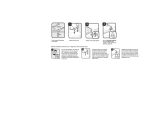
1. Apply grease inside the NSS housing,
thoroughly coating the cam face.
2. Lubricate and insert the new spool
assembly into the NSS housing
(1251).
3. Install the star washer and fingertighten the locknut onto the new
spool.
4. Set the neutral cam with the neutralstart switch in the detent of the cam.
5. Set the new NSS housing gasket
(1255) in place on the mounting
plate.
6. Insert the control spool/NSS
assembly on the pump.
7. Attach the cover with two screws
(1256), torque to 6-8 N•m [8-11 lbf •ft]
8. Torque the spool locknut (1213) to
7-9 N•m [10-12 lbf•ft]
3/8 in
6-8 N·m
[8-11 lbf·ft]
1256
1/2 in
7-9 N·m
[12-23 lbf·ft]
1213
1257
1251
detent
1249
B
1255
Check for free spool movement and spring-return function. It may be necessary loosen
and retorque the screws to prevent binding of the control handle and spool. Do not
tighten the neutral-start adjustment set screw (B) through the expansion plug hole until
pump neutral is set (see final adjustments). If the control neutral is adjusted with the NSS
screw tightened, the vehicle engine may not start.
FINAL ADJUSTMENTS
W Warning
Unintended vehicle
movement hazard
Protect yourself and
bystanders from serious
injury or death. Raise and
secure the drive wheels
off the ground or securely
chock the wheels. Do not
depend on the parking
brake alone for protection.
© Danfoss, 2013
If the pump neutral adjustment bracket was not removed during this procedure, the
pump will be in or very near the neutral set point with the new spool installed. However,
do not assume the neutral set point is correct. Always check for control-neutral either
with servo-pressure gauges or with the wheels-up method, before placing the vehicle
back in service. See M46 Service Manual, BLN-9939 for more information.
1. Install 0-300 psi gauges in both servo test ports.
2. Loosen the washer head screw to allow the neutral adjustment bracket to move, but
not freely.
3. Start the prime mover and slowly accelerate to normal operating speed.
4. Slowly rotate the neutral adjustment bracket until one of the servo gauges begins to
increase pressure. Mark the position.
5. Slowly move the bracket in the opposite direction until the other gauge begins to
increase pressure. Mark the position.
6. Rotate the bracket to a position at the midpoint between the marks and hold
securely in place while torquing the washer head screw to 11-15 N·m [8-11 lbf·ft].
7. Stop the prime mover, remove the gauge and install the gauge port plugs.
8. Reinstall and adjust the control linkage, if necessary.
BLN-10249 • Rev AA • September 2013
2