Download Clamps - Cascade Corporation
Transcript
Manual
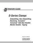
D-Series
Non-Sideshifting and Sideshifting Clamps
40D Turnafork
Serial Numbers 668686 through
Fork Clamps
Bale Clamps
Drum Clamps
Multi-Purpose/Rigid Arm Clamps
Clamps without Arms
Turnafork
Clamps
Manual Number 669224 R-3
cascade
Cascade
is a RegIstered Trademark al Cascade
Corporation
l
Turnafork is a Trademark of Cascade Corporatton
681754
Contents
INTRODUCTION, Section 1 .......................
INSTALLATION INSTRUCTIONS, Section 2 ......
............................
Truck Requirements
lnstallation ......................................
Customer Fabricated Arm lnstallation ...........
Prior to Operation ...............................
PERIODIC MAINTENANCE, Section 3 ............
TROUBLESHOOTlNG, Section 4 .................
General Procedures .............................
Plumbing - 25D, 35D, 40D, 50D Clamps ........
Plumbing - 70D, 80D Clamps ...................
.........................
Clamp Troubleshooting
SERVICE, Section 5 ...............................
................
Clamp Removal and lnstallation
Arms ............................................
Arm Assembly Removal and lnstallation ......
........
Bolt-On Arm Removal and lnstallation
Multi-Purpose/Rigid.and
Drum Arm
Contact Surface Replacement ..............
Rigid Arm Contact Pad Rotation and
Replacement ..................................
Arm Bearing Removal and lnstallation ........
Turnafork Arm Service ........................
Turnafork Arm Indexing .......................
Cylinders ........................................
............
Cylinder Removal and lnstallation
Cylinder Service .................................
Cylinder Disassembly .........................
Cylinder Inspection ...........................
Cylinder Reassembly .........................
Restrictor Cartridges ............................
..............
Restrictor Cartridge Adjustment
Restrictor Cartridge Service ...................
Check Valves ...................................
Check Valve Removal and lnstallation ........
Check Valve Service - 25D, 35D,
40D, 50D Clamps ...........................
Check Valve Service - 70D, 80D Clamps .....
Eliminating the Arm Opening
Regenerative Function ......................
Base Unit .......................................
Frame and Mounting Plate Disassembly
and Reassembly ............................
SPECIFICATIONS, Section 6 ......................
Hydraulics .......................................
Truck Carriage ..................................
Torque Values ...................................
Page
Number
1
1
1
2
5
6
7
8
8
10
13
16
19
19
20
20
21
21
22
22
23
24
25
25
27
27
27
28
29
29
29
30
30
31
32
32
33
33
34
34
34
35
669224
Rev. 3
.
1 Introduction
Section
This manual provides the installation instructions, periodic
maintenance requirements, troubleshooting procedures
and service guides for D-Series Non-Sideshifting and
Sideshifting Clamps and 40DTurnafork. Note that all specifications are shown in US and (Metric) units where applicable.
1.1 Special Instruction
Definitions
A statement preceded by A WARNING is information that
should be acted upon to prevent bodily injury. A
WARNING is always inside a ruled box.
CAUTION
A statement preceded by CAUTION is information that
should be acted upon to prevent Machine Damage.
IMPORTANT
A statement preceded by IMPORTANT is information that
possesses special significance.
NOTE
A statement preceded by NOTE is information that is handy
to know and may make your job easier.
l
Section
2 lnstallation Instruct ions
HydraulicSpecifications
truck/attachment combination is a responsibility of the original truck manufacturer and
may be less than that shown on the attachment nameplate. Consult the truck
Pressure-Maximum
Recommended
Flow-Minimum@
2.1 Truck Requirements
l
Truck Relief Valve Setting:
2300 psi (160 bar), maximum.
2000 psi (140 bar), recommended
Hydraulic flow should fall within the volume range shown
in the table.
The truck hydraulic system must supply oil to the attachment that meets the specifications shown in the table.
l
Recommended
hose and fitting size:
No. 6 with minimum fitting orifices of 9/32 in. (7mm).
No. 8 with minimum fitting orifices of 13/32 in. (1Omm).
0 Truck carriage must conform to IS0 dimensional standard
2328, equivalent to Industrial Truck Association (ITA)
dimensions shown in Section 6.1-2.
669224
l
Make sure the truck carriage is clean and the notches are
undamaged.
l
In order to conform to industry standard practice, the
hoses should be connected to the truck auxiliary valve as
indicated by the chart in Section 6.1-l.
Rev. 3
Recommended
Maximum
250
350,40D
500,70D,
2300 psi
2300 psi 2300 psi
(160bar) (160bar)
(160bar)
2000 psi 2000 psi
(140bar) (140bar)
2000 psi
(140bar)
4 GPM
4 GPM
(15Umin) (15Umin)
4 GPM
(Wmin)
5.5 GPM 7 GPM
(21Umin) (26Umin)
(38Umin)
5.5 GPM 7GPM
(21Umin)
(26Umin)
,,
10GPM
(38Umin)
I
Supply Hose and Fitting Size
Minimum
Orifice Size
8OD
10GPM
1
No.6 (Sideshift)
9/32in.(7mm)
No.8 (Clamp)
13/32in.(10mm)
0
Flow less than minimum will result in unequal arm movement.
0
Flow greater than maximum can result in excessive heating, reduced system performance
and short hydraulic system life.
Hydraulic Oil -Cascade attachments are compatible with SAE
1OWpetroleum base oil per Mil. Spec. MIL-0-5606or
MIL-O-2104B.
Use of synthetic or aqueous base hydraulic oil is not recommended. Contact Cascade if fire resistant hydraulic oil must be
used.
1
Section
2 Installation Instructions
2.2 lnstallation
1
install two 1/2-I3 NC (M 12) eyebolts and a suitable
overhead chain hoist to the frame. Set the clamp vertical
A
2
WARNING: Make sure your overhead
hoist has a rated capacity of at least
2000 Ibs. (900 kg).
Connect the hydraulic hoses to the attachment using
Cascade Attachment lnstallation Kit No. 659245 for
non-sideshifting clamps and clamps with solenoid
adaption, Kit No. 659249 for sideshifting clamps OR use
hoses and fittings as shown.
Position the truck carriage behind the attachment to
determine hose lengths required to connect hoses to the
hose terminal kits. Remove the hose and cut to length as
required.
A
Hoses should not
project above the
Check Valve Bracket.
WARNING: Do not remove the fitting
from the valve clamp (CL) port. For No.
6 hose connection, use a 6-8 reducer.
No. 8 Hoses
(SAE 100 I?5 Type Single
Wire Braid Rubber Covered)
Sideshift right/left
(These hoses apply to
sideshifting clamps only).
\
/
No. 8 Hoses
(SAE 100 R5 Type Single
Wire Braid Rubber Covered)
Close/Open
0
70D, 80D Clamps
Sideshift Left - De-energized
Open - Energized
Sidshift Right - De-energized
Close - Energized
25D, 35D, 40D, 50D Clamps
Sideshift Left - De-energized
Sideshift Right - De-energized
Sideshift Right - De-energized
Close - Energized \
Sideshift Left - De-energized
Open - Energized
250, 35D,,40D, 50D Clamps
Solenoid Adaption with Backrest
2
25D. 35D. 40D. 50D Clamps
Solenoid Adaption without Backrest
669224
Rev. 3
.
Section
2 lnstallation lnstructions
2.2 lnstallation (Continued)
CAUTION: Flush the hoses as follows to prevent damage to
the attachment hydraulic components.
3
Connect hoses to the truck hose terminal kits. Connect
the hoses together using union fittings. Start the truck
and actuate the truck control valves in both directions for
about 30 seconds to carry any debris left in the hoses to
the truck hydraulic tank and filter.
4
Remove the union fittings and disconnect hoses from the
hose terminal kits. Connect hoses to the attachment
fittings as shown in step 2.
5
Install the Quick Change lower mounting hooks. For
Bolt-On type hooks, proceed to step 6.
Quick Change Type A- Install the components as
shown. Tighten the capscrews to a torque of 105-115
ft.-lbs. (140-155 N.m).
Quick Change Type Ba. install the guides to the baseplate mounting holes with
the guide hole offset in the upward position- 5/8 in.
(16mm) from top of guide to hole center. Tighten the
capscrews to a torque of 105-115 ft.-lbs.
b.Slide the hooks over the top of the guides, Install each
locking pin through the hook lower hole.
6
Center the lift truck behind the attachment. Tilt the mast
forward. Engage the mounting hook tab with the closest
upper carriage bar notch and raise the truck carriage
into position behind the attachment, Lift the attachment 2
in. (5cm) off the pallet.
NOTE: The attachment may not be perfectly centered on
the carriage bar when the mounting hook tab is engaged
in the carriage notch.
WARNING: The mounting hooks
must be properly engaged with the
upper carriage bar. The tab on the
left mounting hook must be engaged
in the mating notch on the upper
carriage bar.
NOTE: The lower hooks cannot be properly installed if
the upper hook tab is not engaged in the carriage notch.
669224
Rev. 3
2 lnstallation lnstructions
Section
2.2 lnstallation (Continued)
7
lower carnage bar
Engage the lower hooks with the truck lower carriage bar.
Bolt On type-Install the hooks and capscrews.
Tighten the capscrews finger tight. Tap the end of the
hooks with a hammer in the direction of the adjust
arrow for maximum engagement with the carriage
bar. Tighten the capscrews to a torque of 105-115
ft.-lbs. (140-155 N,m).
Quick Change Type A-Turn both hooks up and
reinstall the pin. The maximum allowable clearance
between the hooks and carriage bar is 118in. (4mm)
as shown.
Bolt On Hooks
Quick Change Hooks
Truck
lower
Quick ChangeType B-Remove the locking pins.
Slide the hooks up to engage with the carriage bar.
Install the locking pins through the upper holes,
CAUTION: If the clearance between the carriage bar
and the hooks exceeds 3/16 in. (6mm), the guides
(refer to step 5) should be inverted and installed with
the hole offset downward - 5/8 in. (16mm) from bottom
of guide to hole center to minimize the gap.
lower hook
Clamp hoses
Hydraulic
8
Quick
I
Optional Hydraulic Quick Disconnect Coupling Kits No,
671045 can be installed at this time. One kit is required
for non-sideshifting clamps, two kits are required for
sideshifting clamps. These kits allow fast removal of the
attachment
from the truck without the use of tools.
Included with the kit is lnstallation Instruction No. 671422.
Each pair of hoses
requires a coupling kit.
9 Connect the attachment hoses to the hose terminal
fittings. See the chart in Section 6.1-i for correct auxiliary
valve and attachment function operation.
669224 Rev. 3
Section
2.2
2 Installation lnstructions
lnstallation
(Continued)
Drive
10 Tighten the arm capscrews as described in step 1 of
Customer Fabricated Arm installation, Section 2.3.
2.3
Extention
Customer Fabricated
Arm lnstallation
(Clamps without Arms)
Clamps without arms are supplied with two arm bases.
Special forks can be welded directly to them or they can be
used as a base to fabricate custom built arms.
WARNING: Use a certified welder and
proper welding procedures when
welding arms to the arm bases.
CAUTION: Weld fabricated arms to the arm bases only. Do
not weld or bolt special built arms or forks directly to the arm
bars.
Arm. Base
The arm base material is AISI C-1020 with the following
specifications:
TENSILE STRENGTH-61,000 PSI min. (420mPa)
YIELD STRENGTH-43,000 PSI min. (3OOmPa)
CARBON CONTENT-23% max.
CAUTION: The surface flatness of the arm base must remain
within ,010 in. (.25mm) in bolt area and arm bars must slide
free manually.
1
Fasten the arm bases to the arm bars. Tighten the
capscrews to the torque values indicated in the chart
with drive extension tool 668020 for 25D attachments,
667699 for 35D, 40D, 50D attachments or 676218 for
70D attachments. A torque multiplier is required to
tighten the 70D capscrews. The torque multiplier and
drive extension tools can be ordered by contacting:
Model
Tool
Part No.
25D
668020
35D
1 667699
669224
Rev. 3
190-220ft.-lbs.
ft.-lbs.
(257-298
N.m)
(380-434
N,m)
667699
280-320ft.-lbs.
(380-434
N,m)
50D
667699
280-320ft.-lbs.
(380-434
N,m)
70D
676218
680-720ft.-lbs.
(922-976
N,m)
DimensionsModel
25D
Short drive adapters are commercially available ref. Williams
%” drive to %” hex (25D) and %” drive to 5/B”hex (35D, 40D,
50D) and 3/4”drive to 3/4”hex (70D). Drive extension tool
dimensions are provided for you to make your own tool from
an allen wrench. Do not use mild steel hex stock.
1
1 280-320
40D
Parts Depot
Cascade Corporation
2501 Sheridan Ave.
Springfield, Ohio 45505
Telephone: (513) 322-1199
Telex: 279563
FAX: (513) 325-9270
IMPORTANT: Be careful not to damage the arm bar.
Premature bearing failure will occur.
Torque Values
for Arm Capscrews
A
.50(12,7)
B
.75(19.0)
in (mm)
C
.461(11.6)
D
350(88.0)
5
Section
2.3
2 lnstallation lnstructions
Customer Fabricated
Arm lnstallation
(Continued)
2
Lubricate the cylinder rod threads. nut threads and
spherical portion of nut with STP.
3
Install the washer on the rod end with the beveled side
facing the lug.
4
Engage the rod end into the lug.
5
Tighten the rod end nut to the torque values below,
Prevent rod turning by using wrench on hex washer.
25D, 35D, 40D, 50D - 150-l 75 ft.-lbs. (203-237
70D- 222-250 ft.-lbs. (305-340
N.m)
N,m)
NOTE: The rod end nut is being tightened against the
hex washer. The nut will not be tight against the arm
base lug. This looseness allows for cylinder alignment
during clamping.
6
Install the locking cap and cotter pin.
7
Lubricate the bearing portion of the arm bars with a
thin film of chassis grease.
Hex washers beveled
side facing lug
Prior to Operation
1 Check the cylinder anchor nuts for properly installed
locking caps and cotter pins.
2 Check for external leaks at the fittings and rod ends.
NOTE: The 25D, 35D, 40D and 50D clamps utilize a
regenerative hydraulic circuit in the arm opening
mode. The arms will open at a faster speed than when
closing. This is a normal clamp function. If required the
regenerative function can be eliminated. Refer to
Section 5.6-2.
3
Check for
properly installed
locking caps
and cotter pins
Check for equal arm travel. If the travel is unequal, the
restrictor cartridges can be adjusted as follows:
a. Loosen the jam nuts on the restrictor cartridges.
Screw in the plungers until they bottom. Screw each
plunger out three full turns.
Restrictor
Cartridge
b. Activate the arms to the fully open position,
c. Activate the arms to close until one arm bottoms out.
Measure the amount of stroke remaining in the
opposite arm.
d. If the unequal closing movement exceeds 2 in.,
screw the plunger in l/2 turn on the cylinder that
bottomed first.
e. Repeat steps b through cl until unequal closing
movement is less than 2 in.
4 Before picking up a load, operate the clamp through
several full cycles to force any air from the system to
the hydraulic tank.
WARNING: Make sure there are no
people in the vicinity of the attachment
when picking up a load.
6
669224
Rev. 3
Section
3
Periodic Maintenance
3.1 100 Hour
Maintenance
Every time the lift truck is serviced or every 100 hours of truck
operation, whichever comes first, complete the following
maintenance procedures:
After completing any service procedure, always test each
function through 5 complete cycles. First test the clamp
test each function with a load to make sure the attachment
operates correctly before returning it to the job.
Inspect the cylinder anchor nuts for correct hold.
q Apply wheel bearing grease to the spherical portion of
the cylinder anchor nuts.
Arm bearing life can be extended with periodic light
lubrication. If your application warrants, apply a thin film
of chassis grease to the bearing portion of the arm bars.
IMPORTANT: Tighten the arm capscrews. A torque
multiplier is required to tighten the 70D, 80D capscrews.
Refer to Section 2.3.
3.2
500 Hour
Maintenance
After each 500 hours of lift truck operation, in addition to the
IOO-hour maintenance procedures, perform the following:
Tighten the lower hook capscrews. Use the torque
specifications shown in Section 6.l-3.
Cl 70D, 80D Clamps-Tighten
the upper hook capscrews.
Use the torque specification shown in Section 6.1-3.
3.3 1000 Hour
Maintenance
After each 1000 hours of lift truck operation, in addition to the
lOO-hour and 500-hour maintenance procedures, perform
the following.
Inspect the arm bearings. If the bearings are worn in any
area to a thickness less than ,040 in. (1 mm), they must be
replaced. See Section 5.2-5.
3.4 2000 Hour
Maintenance
After each 2000 hours of lift truck operation, in addition to the
IOO-hour, 500-hour, and IOOO-hour maintenance procedures,
perform the following procedures.
Cl Replace all arm bearings. See Section 5.2-5.
Tighten the frame/mounting plate capscrews. Use the
torque specification shown in Section 6.1-3.
669224
Rev. 3
7
Section
4 Troubleshooting
General Procedures
A
After completing any service procedure,
always test the function through several
cycles. First test the attachment empty to
bleed airtrapped in the system to the truck
system. Then test the attachment with a load
to be sure it operates correctly before returning it to the job.
I
Stay clear of the load while testing. Do not
raise the load more than 3 in. (7cm) off floor
while testing.
4.1-1 Truck System Requirements
4.1-2
Hydraulic Specifications
WARNING:
Before servicing any hydraulic
component, relieve pressure in the system.
Turn the truck off, and open the truck auxiliary valves several times in both directions.
l
The lift truck must supply sufficient hydraulic pressure to
handle the heaviest load. PRESSURE MUST NOT
EXCEED 2300 PSI (160 BAR).
l
Hydraulic flow should fall within the volume range shown in
the table.
l
The truck hydraulic system must supply hydraulic oil to the
attachment that meets the specification shown in the table.
35D, 40D
25D
Pressure-Maximum
Recommended
500,70D,
80D
2300 psi 2300psi
(160bar) (160bar)
2300 psi
(160bar)
2000 psi 2000psi
(140bar) (140bar)
2000 psi
(140bar)
4 GPM
4GPM
(15L/min) (15L/min)
4 GPM
(l5L/min)
Recommended
5.5 GPM 7 GPM
(21L/min) (26L/min)
10GPM
(38L/min)
Maximum
5.5 GPM 7 GPM
(21L/min) (26L/min)
10GPM
(38L/min)
Flow-Minimum@
Supply Hose and Fitting Size
Minimum Orifice Size
No.6 (Sideshift)
9/32in.(7mm)
No.8 (Clamp)
13/32in.(1Omm)
0
Flow less than minimum wtll result in unequal arm movement.
0
Flow greater than maximum can result in excessive heating, reduced system performance
and short hydraulic system life.
Hydraulic Oil-Cascade
attachments are compatible
1OWpetroleum base oil per Mil. Spec. MIL-0-5606or
MIL-O-2104B.
with
SAE
Use of synthetic or aqueous base hydraulic oil is not recommended. Contact Cascade if fire resistant hydraulic oil must be
used.
Tools Required
FLOW
METER
In addition to a normal selection of hand tools, you will need:
l
A flow meter capable of measuring hydraulic flow to 20
GPM (75 L/min.). The parts shown are included in
Cascade Flow Meter Kit Part No. 671477.
l
A pressure gauge capable of measuring pressure to 2500
psi (175 bar). The parts shown are included in Cascade
Pressure Gauge Kit Part No. 671212.
l
Assorted fittings and a No. 6 hose, as shown, to adapt the
gauge and flow meter to the components being tested.
(2) No. 6-8 JIC Reducer
PRESSURE
GAUGE
Pressure
No. 4-6 Pipe/JIC
No. 6 and No. 8
No. 6-8 JIC
Reducer
*No. 6-8
JIC/O-ring
I
I
*Not
included in Pressure Gauge Kit part no. 671212
669224
Rev. 3
Section
4 Troubleshooting
4.1-3 Get All The Facts Before You
Begin Working On The
Clamp
It IS Important that you gather all the facts regarding the
problem before you begin service procedures. The best way
IS to talk with the operator. Ask for a complete description of
the malfunction. The following guidelines will help you
decide where to begin your troubleshooting procedures.
NOTE: The 25D, 35D, 40D and 50D clamps utilize a
regenerative hydraulic circuit in the arm opening mode.
The arms will open at a faster speed than when closing.
This is a normal clamp function.
l
Clamp drops load after it has been picked up.
Clamp Will not carry load up to its rated capacity.
l
Clamp arms have uneven travel
Clamp arms travel slowly.
Clamp arms Will not move.
If you encounter
4.4-l.
one of these problems, refer to Paragraph
Clamp drops the load when sideshifting.
If you encounter
669224
Rev. 3
this problem, refer to Paragraph 4.4.
9
Section
4 Troubleshooting
4.2
Plumbing - 25D, 35D, 40D, 5OD Clamps
4.2-l
Hosing Diagram, Non-Sideshifting
Clamps
Cylinder
ARMS OPENING
PRESSURE
REGENERATING
4.2-2
Circuit Schematic,
ARMS CLOSING
Hose
Terminal
Non-Sideshifting
Clamps
Valve
10
Truck
Hydraulic
Pump
669224 Rev. 3
Section
4.2-3
4 Troubleshooting
Hosing Diagram, Sideshifting Clamps
(including Turnafork)
PRESSURE
REGENERATING
Hose
Terminal
Clamps with
Solenoid Adaption
Hose
Reel
ARMS CLOSING
PRESSURE
RETURN
Clamps with
Solenoid Adaption
Auxiliary
Valve
Hose
Terminal
Hose
Reel
669224
Rev. 3
11
Section
4.2-3
4 Troubleshooting
Hosing Diagram, Sideshifting Clamps (Cont.)
Cylinder
SlDESHlFTlNG
(SIDESHIFT LEFT SHOWN)
PRESSURE
RETURN
SLAVE
Hose
Terminal
solenoid
Hose
Terminal
Hose
Terminal
4.2-4
Hose
Reel
Auxiliary
valve
Circuit Schematic, Sideshifting Clamps
(including Turnafork)
Cylinders
Clamps with
Solenoid Adaption
Hose
Terminal
V
w
Hose
reel
Clamp
Auxiliary
Valve
Sideshift
Auxiliary
Valve
A
Truck
Relief Valve
Truck
12
Relief Valve
I
Truck
Hydraulic
669224
Pump
Rev. 3
Section
4
Troubleshooting
4.3 Plumbing - 70D, 80D Clamps
Hosing Diagram, Non-Sideshifting
4.3.1
Clamps
Check
Valve
ARMS OPENING
ARMS CLOSING
Hose
Terminal
PRESSURE
RETURN
4.3-2
Circuit Schematic, Non-Sideshifting
Clamps
A
Cylinders
I
Check
Valve
’
L
Clamp
-
Valve
669224
Rev. 3
Truck
Hydraulic
Pump
13
Section
4 Troubleshooting
4.3-3 Hosing Diagram, Sideshifting Clamps
ARMS OPENING
To cylinders
Hose
Terminal
Clamps with
Solenoid Adaption
valve
Hose
Terminal
Hose
Reel
e
I
ARMS CLOSING
PRESSURE
RETURN
To Cylinders
Hose
Terminal
14
669224
Rev. 3
Section
4.3-3
4 Troubleshooting
Hosing Diagram, Sideshifting
Clamps
(Cont.)
SlDESHlFTlNG
(SIDESHIFT LEFT SHOWN)
PRESSURE
RETURN
To Cylinders
Hose
Terminal
Hose
Terminal
4.3-4
Circuit Schematic, Sideshifting Clamps
Cylinders
Clamps with
Solenoid Adaption
IA,..-.3
M-l
-h
V
PI
G
V
r -‘-!
Hose
Hose
reel
Clamp
Auxiliary
Valve
Sideshift
Auxiliary
Valve
Truck
Relief
Valve
Truck
Hydraulic
Pump
Truck
Relief
Valve
Truck
Hydraulic
Pump
15
669224 Rev. 3
Section
4 Troubleshooting
4.4 Clamp Troubleshooting
There are four potential problem areas that could affect
clamping force.
0
Insufficient hydraulic pressure from the lift truck.
0
External leaks
0
Malfunctioning
check valve.
Worn or defective cylinder seals.
To isolate the problem area, complete the following check list
in the exact sequence indicated.
4.4-l
1
WARNING: Before removing any
hoses or fittings relieve pressure in the
hydraulic system. Turn the truck off. then
open the truck auxiliary control valves
several times in both directions.
Clamp Circuit Pressure Test
1. Check the pressure delivered by the truck. Refer to the
truck service manual. The pressure must be within
100 psi (7 bar) of specified truck pressure. TRUCK
PRESSURE MUST NOT EXCEED 2300 PSI (160 Bar),
measured at the junction block.
2.
Check the flow volume at the hose terminal. See
Paragraph 6.1-l for the recommended flow volumes.
If the truck pressure and flow volume are correct,
proceed with the pressure test.
3.
Clamps with Solenoid Adaption - Press the auxiliary
valve control knob button. Listen for a “click’ at the
solenoid valve. If the solenoid valve does not “click”
when the button is pushed, check the electrical wiring
and solenoid coil.
4
Check for external leaks. Start the truck. Close the arms
fully. Hold the clamp control handle In the clamp
positron for a few seconds.
5.
Return the handle to neutral. Inspect all fittings, lines,
and the cylinders for leaks. If there are no leaks,
proceed with the pressure test.
90’ fitting
and hose
6. 25D, 35D, 40D, 50D Clamps - Install the pressure
gauge and hose assembly in the valve test port
marked “G”. located on the back of the valve body.
70D, 80D Clamps- Remove the bumper. Install a tee
fitting. hose and gauge between the cylinder rod end
supply hose and tee fitting as shown.
7
Start the truck. Close the arms fully. Hold the clamp
control handle in the clamp position for a few seconds.
8.
Return the handle to neutral. Watch the gauge pressure reading.
l
If the pressure does not drop more than 150 PSI
(10 bar) initially, and additional drop does not exceed
25 PSI (2 bar) per minute. the problem is not
hydraulic. Refer to Paragraph 4.1-3.
l
If the pressure drops more than 150 psi (10 bar)
initially. and additional drop exceeds 25 psi (2 bar)
per minute, proceed with the troubleshooting check
list to isolate the faulty component.
IMPORTANT: Before removing pressure gauge.
momentarily actuate clamp open circuit. This will
relieve pressure trapped by the check valve in the
clamp circuit
Install tee fitting,
and gauge.
16
hose
669224
Rev. 3
Section
4 Troubleshooting
4.4-2
Check Valve Pressure Test
WARNING: Before removing any
hoses, relieve pressure in the hydraulic
system. Turn the truck off, then open
the truck auxiliary control valves several
times in both directions.
1. 25D, 35D, 40D, 50D Clamps2.
Remove the bumper.
Disconnect the hydraulic lines at the rod end of both
cylinders. Cap the ports and plug the lines.
3. Start the truck. Hold the clamp control handle in the
clamp position for a few seconds.
4.
25D ,35D,
40D, 50D
Clamps
Return the handle to neutral. Watch the gauge pressure reading.
Disconnect the hydraulic lines
at the rod end of both cylinders.
Cap the ports and plug the lines.
0 If the pressure drops more than 150 psi (10 bar)
initially, and additional drop exceeds 25 psi (2 bar)
per minute, the check valve is faulty and requires
service. Refer to paragraph 5.5-3
0 If the pressure does not drop more than 150 psi
(10 bar) initially, and additional drop does not
exceed 25 psi (2 bar) per minute, one or both cylinders require service. Proceed with the troubleshooting check list to isolate the faulty component.
IMPORTANT: Before removing pressure gauge,
momentarily actuate clamp open circuit. This will relieve
pressure trapped by check valves in clamp circuit.
4.4-3 Cylinder Test
hoses, relieve pressure in the hydraulic
system. Turn the truck off, then open
the truck auxiliary control valves several
25D, 35D,
40D, 50D
Clamps
1, Connect one of the hydraulic lines to its cylinder. The
other line must remain plugged.
2. Start the truck. Hold the clamp control handle in the
clamp position for a few seconds.
3.
Return the handle to neutral. Watch the gauge pressure reading.
l
If the pressure drops more than 150 psi (10 bar)
initially, and additional drop exceeds 25 psi (2 bar)
per minute, the cylinder connected to the check
valve is faulty and requires service. Refer to paragraph 5.3-l
Connect one of the hydraulic lines
to its cylinder. The other line must
remain plugged.
0 If the pressure does not drop more than 150 psi
(10 bar) initially, and additional drop does not exceed
25 psi (2 bar) per minute, the second cylinder is
faulty. Refer to paragraph 5.3-l.
It is recommended to perform a similar pressure test
for the second cylinder before servicing.
IMPORTANT: Before removing pressure gauge,
momentarily actuate clamp open circuit. This will relieve
pressure trapped by check valves in clamp circuit.
669224
Rev. 3
17
Section
4.4-4
4 Troubleshooting
Sideshift Circuit
Pressure Test
Install fitting, hose
and gauge.
If the clamp does not sideshift right and left at equal
speeds or drops a load while sideshifting, one of the
sideshift check valves cartridges is faulty. The two outer
cartridges on the front of the valve are for the sideshift
circuits.
IMPORTANT: Clamps equipped with solenoid adaption
must be plumbed to the check valve so the solenoid will be
energized for the clamp/open functions.
WARNING: Before installing the pressure gauge, relieve pressure in the
hydraulic system. Turn the truck off,
then open the truck auxiliary control
valves several times in both directions.
1. 25D, 35D, 40D, 50D Clamps- Install the pressure
gauge and hose assembly in the valve test port
marked “G”, located on the back of the valve body.
70D, 80D Clamps- Remove the bumper. Install a tee
fitting, hose and gauge between the cylinder rod end
supply hose and tee fitting as shown.
Sideshift Left
Cartridge
2. Stan the truck. Clamp onto a load (lift no more than 1” off
ground or floor). Hold the sideshift control handle in the
sideshift left position for a few seconds.
3. Return the handle to neutral. Watch the gauge
pressure reading.
l
If the pressure drops more than 150 psi (10 bar)
initially, and additional drop exceeds 25 psi (2 bar)
per minute, the sideshift left cartridge is faulty and
requires service. Refer to paragraph 5.53.
l
If the pressure does not drop more than 150 PSI
(10 bar) initially, and additional drop does not exceed
25 psi (2 bar) per minute, move the sideshift control
handle in the sideshift right position for a few
seconds.
4. Return the handle to neutral. Watch the gauge pressure reading.
l
If the pressure drops more than 150 psi (10 bar)
initially, and additional drop exceeds 25 psi (2 bar)
per minute, the sideshift right cartridge is faulty and
requires service. Refer to Paragraph 5.5-3.
l
If the pressure does not drop more than 150 psi
(10 bar) initially, and additional drop does not exceed
25 psi (2 bar) per minute, the problem is not
hydraulic.
Install tee fitting, hose
and gauge.
WARNING: Before removing the pressure gauge, relieve pressure in the
hydraulic system. Turn the truck off
then open the truck auxiliary control
valves several times in both directions,
la
18
669224
Rev. 3
Section
5 Service
5.1 Clamp Removal and
lnstallation
1
Extend the arms outside the width of the frame.
2
Disconnect the Lower Hooks.
Bolt On Type- Remove the lower mounting hooks. For
reassembly, tighten the capscrews to a torque of:
Class ll/lll Mounting - 105-115 ft.-lbs. (140-155 N,m)
Class IV Mounting - 180-200 ft.-lbs. (244-270 N.m)
Quick Change Type A- Pull out the retaining pin and
rotate the hooks to the position shown. For reassembly,
turn both hooks up and reinstall the pin.
Quick Change Type B- Pull out the retaining pin, slide
the hook down and reinstall the pin in the lower hole. For
reassembly, slide the hook up and install the pin in the
top hole.
3
Place a pallet under the attachment. Lower the mast
carriage until the attachment is resting on the pallet with
2 x 4 in. (5 x 10cm) blocks placed as shown.
4
On attachments with forks, set a 1000 lb. (450kg) weight
on the forks to hold the attachment upright.
NOTE: Attachments with load arms other than forks
don’t require additional stabilizing weight.
669224
5
Disconnect and plug the hoses to the attachment. Tag
the hoses for reassembly.
6
Making sure the weight on the forks is secure, continue
lowering the mast carriage enough to clear the upper
mounting hooks. Back the truck away.
7
For installation, reverse the above procedures, or consult
the lnstallation lnstructions. Section 2.
Rev. 3
Pin
19
Section
5.2
5.2-l
5 Service
Arms
Arm Assembly Removal and
lnstallation
The following procedures
can be performed
attachment
mount on the truck
with the
1
Extend the arms. Lower the attachment
to
position the forks or arms 1/2 in. (12mm) above the
floor. Remove the cotter pin, locking cap and nut
retaining the cylinder rod to the arm lug.
2
attach a suitable overhead
hoist and chain to the arm.
Chain must be kept away from the arm bearing Surface.
WARNING:
Make sure your overhead
hoist has a rated lifting capacity of at
least 1000 Ibs. (450kg).
3
Retract the cylinder rods
until they
engagement
with the arm lugs.
WARNING:
from under
come out of
Keep your feet and fingers
the forks or arms.
out
4
Pull the arm assembly
out of the frame
5
Inspect the arm bearings for wear. If the bearings are
worn in any area to a thickness
less than .040 in.
(1 mm) they must be replaced. See Paragraph
5.2-5 for
removal and installation.
6
For reassembly.
for the following
nuts.
reverse
special
l
Lubricate
spherical
l
Install the hex washer
side facing the lug.
l
Engage
the above procedures.
except
instructlons
for cylinder anchor
the cylinder rod threads.
portion of nut with STP.
nut threads
and
on the rod end with the beveled
the rod end into the lug.
lTighten
the rod end nut to the torque values below.
Prevent the rod from turning by using a wrench on
the hex washer.
25D, 35D, 400, 50D - 150-l 75 ft.-lbs. (200-235
70D, 80D - 225-250 ft.-lbs. (305-340
Hex washer
beveled side
facing lug
Arm lug
N,m)
N.m)
NOTE: The rod end nut IS being tightened against the hex
washer. The nut Will not be tight against the arm lug. This
looseness allows for cylinder alignment during clamping.
20
l
Install
the locking
cap and cotter
l
Lubricate the bearing portion
thin film of chassis grease.
pin
of the arm bars with a
669224
Rev. 3
Section
5 Service
5.2-2 Bolt-on Arm Removal
Drive Extension
The following procedures can be performed with the
attachment on the truck and with the arm assemblies on the
attachment. If the arm assemblies have been removed
(Paragraph 5.2-l), lay the arm assembly down with the arm
back on the ground.
0
Extend the arms outside the width of the frame. Remove
the cotter pin, locking cap and nut retaining the cylinder
rod to the arm lug.
0
Remove the arm capscrews using drive extension tool
part no. 668020 for 250 attachments, 667699 for
35D, 40D and 50D attachments or 676218 for 70D,
8OD attachments, A torque multiplier is required to
remove and tighten the 70D, 80D capscrews.
I-‘1
Short drive adapters are commercially available: Ref.
Williams l/2” drive to 1/2”hex (25D) and 1/2”drive to 5/8”hex
(35D, 40D, and 50D). Driver extension tool dimensions are
provided for you to make your own tool from an allen
wrench. Do not use mild steel hex stock.
u--U -
c
D
Dimensions- In (mm)
A
B
I
C
D
IMPORTANT: Be careful not to damage the arm bar.
Premature bearing failure will occur.
0
For reassembly, reverse the above procedures, except
for the following special instructions.
lTighten
the capscrews (lubed) to the torque values
indicated in the chart. Arms should be free to slide in
the frame manually. If necessary, realign and
retorque the capscrews.
IMPORTANT: Be careful not to damage the arm bar.
Premature bearing failure will occur.
2506m
I
Model
I
Tool
Part No.
TorqueValues
for Arm Capscrews
I
190-220ft.-lbs. (257-298 N.m)
l
Install the cylinder anchor nuts as described in
Paragraph 5.2-l) step 6.
280-320 ft.-lbs. (380-434 N,m)
280-320ft.-lbs. (380-434 N,m)
IMPORTANT: To insure proper bolt life, capscrews
must be torqued to values shown in chart. If lost or
broken, replace only with similar GRADE 8 (IS0
property class 10.9) hex socket head capscrews.
5.2-3
680-720
ft.-lbs. (922-976 N,m)
Multi-Purpose/Rigid and Drum Arm
Contact Surface Replacement
0
Drill out the rivets using 3/16 in. (4.8 mm) drill bit. Drill
from the back side of the arm.
0
Multi-Purpose/Rigid
Arm Contact Pad Service Kits
include rivets and optional capscrews to be used
instead of the rivets if required. Drum Arm Service Kits
include rivets only.
Rivet lnstallation - Align the new contact surface to
the arm. Drill through using a 3/l 6 in. (4.8 mm) drill bit.
Rivet the contact surface to the arm.
Optional Capscrew lnstallation - Align the new
contact surface to the arm. Drill the holes along the
front edge of the arm, through the contact pad, with
a No. 7 tap drill. Drill the rest of the hoses with a
l/4 in. (6 mm) drill bit. Install the self-tapping cap
screws in the front edge holes. Install the button head
capscrews through the contact pad. Install the nuts
and tighten. The capscrew heads should be well
below the contact pad surface.
669224
280-320 ft.-lbs. (380-434 N.m)
Rev. 3
Rivet
,Nut/ Rivet
Front edge
holes
21
Service
Section
5
5.2-4
Rigid Arm Contact Pad
Rotation and Replacemerit
The following procedures can be performed with the
attachment mounted on the truck.
NOTE: The contact pads do not have a replaceable surface.
If a pad is completely worn, it must be replaced. If only the
lower section of the pads are worn, the pads can be swapped
side for side and reinstalled.
5.2-5
0
Remove the capscrews and nuts fastening the contact
pad to the stabilizer.
0
Remove the contact pad and swap side for side or
install new pads. Tighten the capscrews to torque of
60-65 ft.-lbs. (80-88 N.m).
Arm Bearing Removal and
lnstallation
Arm bearings can be removed with the attachment mounted
on the truck.
0
Remove the arm assemblies from the attachment
described in Section 5.2-l.
0
Remove the bearing spacer located between the
upper and lower bearing in each arm carrier slot.
@
Pry the bearing strips out of the frame with a screwdriver and slide outward.
CAUTION:
as
Do not gouge aluminum frame surfaces.
NOTE: To ease removal of the first bearing strip from
the frame, push the innermost boss out of its hole.
0
For reassembly, reverse the above procedures.
Inner-most boss
Boss
push here
Frame
0
L\""""\'\\'\\""'-\""""'-"'y
Slide outward ___)
22
669224
Rev. 3
Section
5 Service
5.2-6 Turnafork Arm
Service
arm assemblies can be disassembled
the attachment mounted on the truck.
The Turnafork
with
0
Fully extend the arm assemblies. Position the bottom of
the fork arm
in. (6mm) above a pallet as shown.
0
Remove the front cover. For reassembly, tighten the
capscrews to a torque of 65-70 ft.-lbs. (80-95 N.m).
WARNING: Do not operate the arm
assembly on early style arms with the
front cover removed. If the arm assembly
does not have a snap ring retaining the
bellcrank, it must not be operated. Early
style arms can be operated without the
front cover only if the fabricated bar
shown on page 24 is installed.
0
Remove the two springs from the selector plate pin.
0
Remove the snap ring retaining the bellcrank (if
equipped). Remove the bellcrank and springs.
0
Push the crank
0
Remove the twelve socket head capscrews retaining
the fork arm bearing. For reassembly, tighten the capscrews to a torque of 120-I 30 ft.-lbs. (160-l 75 N,m).
bar inward and remove the selector
A
plate.
L
0
Remove
the fork arm and bearing
WARNING: If the arm
assembly does not have
a snap ring retaining
the bell crank, it must
not be operated with
the front cover removed
without the fabricated
bar shown on page
19 installed.
from
the arm carrier by rotating and pulling
forward on the fork arm. The bearing has a
pivot shaft on its back side that must be
pulled clear of the arm carrier.
NOTE: The crank
with the fork arm.
0
Remove
the detent
bar will be removed
pin, spring,
bushing
and wear plate.
Arm Carrier
Fork’ Arm
.
669224 Rev. 3
23
Section
5.2-6
5 Service
Turnafork Arm
0
Service
(Cont.)
Remove the crank bar from the fork arm bydriving out the
pivot pin from the front side of the fork arm.
Crank Bar
@ Tap the bearing out of the fork arm from the back side
with a rubber mallet.
@ To remove the actuator, the upper arm bar must be disassembled from the arm carrier. Remove the SIXupper arm
capscrews. as described In paragraph 5.2-2 step 2.
Slide the arm bar inward to gain access to the actuator.
@ Remove the snap ring retaining the actuator to the arm
carrier (if equipped). Remove the actuator from the back
side of the arm carrier.
Fork Arm Bearing
@ For reassembly. reverse the above procedures except
as follows:
l
Inspect all components and bushings for wear.
Replace all worn components.
l
Replace the fork arm-bearing
l
Inspect the detent pin. spring, bushing and wearplate. Replace all worn parts.
l
Lubncate the fork arm bearing with chassis
grease prior to inserting into the fork arm.
l
Use two of the bearing capscrews 180” apart as
guides to align the bearing/fork arm with the
arm carrier mounting holes during reassembly.
l
Make sure the arm turns freely on the bearing after
tlghtening the capscrews.
O-ring if damaged.
o Lubricate all zerk fittings with chassis grease.
.
5.2-7
l
On early style arms without a snap ring retaining
on bellcrank. the fabricated bar shown below must
must be installed. This bar allows the arms to be
indexed with the covers off to adjust the horizontal
and vertical stops.
l
The two capscrew stops should be adjusted so the
arm stops at a true horizontal and vertical position
when it is indexed. In the vertical (clamp) position,
the capscrew should stop the arm so it just engages
the detent pin in the arm base. Tighten the nuts to a
torque of 80-90 ft.-lbs. (11 O-l 22 N,m).
Arm Carrier
Turnafork Arm Indexing
Fully closing the arms depresses the actuators. This
releases the locking mechanism and causes the arms to
rotate. If the arms get out of phase (one or both arms not
horizontal or vertical), correct the problem as follows:
IMPORTANT: if the arms ever get out of phase. there may
be nothing mechanically wrong with the attachment. This
condition usually occurs when the actuators are not fully
depressed.
To reposition an arm manually: With the arms fully closed
(actuators fully depressed). reposition one arm by hand.
To reposition an arm hydraulically: Close the arms
hydraulically (actuators fully depressed). Then open the arm
slowly until you hear one click. lmmediately close the arms
together again to bring them back in phase.
24
669224
Rev. 3
Section
5 Service
5.3 Cylinders
5.3-1 Cylinder Removal and
lnstallation
The following procedures can be performed with the
attachment mounted on the truck.
0
Extend the arms outside the width of the frame.
0
Remove the bumper from the attachment.
0
Remove the cotter pins. locking caps and nuts
retaining the cylinder rods to the arm lugs.
0
Retract the cylinder rods until they come out of
engagement with the arm lugs.
0
Relieve hydraulic system pressure.
A
0
WARNING: Before removing any
hydraulic lines, relieve pressure in the
hydraulic system. Turn the truck off,
then open the truck auxiliary control
valves several times in both directions.
Disconnect the hydraulic lines from the cylinder ports
Plug the lines and cap the cylinder ports.
@ Remove the cotter pins, locking caps and nuts
retaining the cylinder to the frame lugs.
0
669224
Lift the, cylinders away from the clamp frame.
Rev. 3
25
Section
5.3-1
5 Service
Cylinder Removal and
lnstallation (Continued)
0
For reassembly. reverse the above procedures, except
for the following special instructions for the cylinder
anchor nuts and the bumper.
0 Install the bumper. Tighten the self-locking nuts to
leave .050-,080 in. (1.3-2.0mm) end play for each
capscrew. This clearance allows for cylinder alignment during clamping without overstressing the
capscrews.
/
0 Lubricate the cylinder rod threads, nut threads and
spherical portion of nut with STP.
l
Install the washer on the rod end with the beveled side
facing the lug.
l
Engage the rod end into the lug.
l
Tighten the rod end nut to a torque of 150-l 75 ft.-lbs.
(200-230 N,m). Prevent the rod from turning by using
a wrench on the hex washer.
Arm lug
Hex washer
beveled side
facing lug
I
@Tighten the rod end nut to the torque values below.
Prevent the rod from turning by using a wrench on
the hex washer.
25D, 35D, 40D, 50D - 150-175 ft.-lbs. (200-235 N.m)
70D, 80D - 225-250 ft.-lbs. (305-340 N.m)
NOTE: The rod end nut is being tightened against the hex
washer. The nut will not be tight against the arm lug. This
looseness allows for cylinder alignment during clamping.
l
Install the locking cap and cotter pin.
l
Lubncate the bearing portion of the arm bars with a thin
film of chassis grease.
Tighten rod end nut.
Operate the attachment through several full cycles to force
air in thesystem to the truck hydraulic tank. Check for leaks.
26
669224 Rev. 3
Section
5 Service
5.4 Cylinder Service
5.4-1 Cylinder Disassembly
0
Clamp the cylinder in a soft-jawed vise. Clamp at the
extreme base end only.
0
Remove the retainer by using a claw type spanner
wrench.
0
Remove the rod assembly from the cylinder
0
Clamp the rod assembly, on the wrench flats. Never
clamp directly
on the rod sealing
surface.
0
Remove the nut fastening the piston to the rod. Use a
wrench on the rod end wrench flats to keep the rod from
rotating while removing the nut.
0
Place the piston or retainer in a soft-jawed vise to
remove the seals. Pry the seals up with a blunt
screwdriver. Cut the seal to remove it.
CAUTION:
Do not scratch the seal grooves
5.42 Cylinder Inspection
0 Inspect the rod, piston, and retainer for nicks or burrs.
Minor nicks and burrs can be removed with emery cloth. If
they cannot be removed with emery cloth, replace the part.
0 Inspect the cylinder shell bore and remove any minor
nicks or burrs with a butterfly. If they cannot be removed
with the butterfly, the shell must be replaced.
l
669224
Inspect the outside of the shell for any deformities, that
could weaken the shell’s performance when under
pressure. Replace if necessary.
Rev. 3
27
Section 5
Service
5.4-3 Cylinder Reassembly
0
Lubricate all new seals and rings with petroleum jelly or
equivalent.
0-
Note the direction of the U-cup seals. If installed
backwards the seals will not work properly. For proper
seal placement see illustration below.
0
Polish the piston and retainer chamfer angle with emery
cloth. This allows the seal to slide over the chamfer
easier.
0
Install the new seals on the piston and retainer. Hook
one side of the seal in the groove and push it over the
piston or retainer as shown.
0
Install the piston on the rod and tighten the piston
retaining nut. Tighten to the torque value shown below.
0
Place the piston loader rn the cylinder shell. The loader
must cover all of the threads but not contact the thread
relief chamfer. The length of the stop fins can be
trimmed with a sharp knife if more engagement IS
needed. The piston will not enter the shell if the loader
contacts the thread relief chamfer.
Do not allow lower
edge of loader to
relief
Stop
fins
Cylinder shell
Apply a thick film of petroleum jelly to the inside of the
cylinder shell, piston loader and piston seals.
0
Insert the rod-piston assembly through the loader into
the cylinder shell. If resistance IS encountered, tap the
rod end with a rubber mallet.
Remove the loader from the shell.
CAUTION:
Do not scratch the cylinder bore
@ Place the retainer loader over the rod end.
@Apply a thick film of petroleum jelly to the inside of the
cylinder shell, retainer loader and all retainer seals.
@Slide the retainer over the retainer loader and screw it
into the shell. Remove the retainer loader. Tighten the
retainer to the torque value shown.
25D. 35D -75-125
40D, 50D -75-125
70D. 80D -325-375
i
ft.-lbs. (100-170
ft.-lbs. (100-170
ft.-lbs. (440-508
N.m)
N.m)
N.m)
Install the piston on the rod and
tighten the retaining nut.
Tighten to a torque of:
25D. 35D -55-70
ft.-lbs. (75-95
N.m)
40D. 50D -90-110
ft.-lbs. (125-145
N,m)
70D, 80D -400-425
ft.-lbs. (542-575
N,m)
28
669224
Rev. 3
Section
5 Service
5.5 Restrictor
Cartridges
5.5-1 Restrictor Cartridge
Adjustment
The restrictor cartridges must be adjusted so that the arms
have equal travel during opening and closing.
NOTE: Current production cylinders have the restrictor
cartridge installed in the rod end port. Early production
cylinders have the restrictor cartridges installed in the
base end port.
Restrictor Cartridge
(Current location in
cylinder rod end Port
PRESSURE MUST NOT EXCEED 2300 PSI (160 BAR).
Hydraulic flow should fall within the volume range shown
in Section 6.1-l.
0
Remove the bumper if the restrictor cartridges are
installed in the cylinder rod end ports.
@ Loosen the jam nuts on the restrictor cartridges. Screw
in the plungers with a screwdriver until they bottom,
then back off three full turns.
0
Operate the attachment to determine the arm speed.
0
Screw in plunger on faster arm until equal in closing.
If not equal on opening, screw in plunger on faster arm
until equal on opening and closing. Back off plungers
equally until arms start to lose equalization. Tighten the
jam nuts.
0
If the arm travel will not equalize and the restrictor
cartridges are installed in the cylinder base end ports,
remove the cartridges and reinstall in the rod end ports
and readjust.
0
Install the bumper as described
in Section 5.3-l step 9.
Plunger,
Restrictor Cartridge Service
5.5-2
WARNING: Before removing a restrictor
cartridge, relieve pressure in the
hydraulic system. Turn the truck off, then
open the truck auxiliary control valves
several times in both directions.
.
0
Remove the bumper if the restrictor cartridges are
installed in the cylinder rod end ports.
0
Remove the restrictor cartridge from the cylinder port.
For reassembly tighten to a torque of 1O-l 5 ft.-lbs.
(13-20 N.m).
0
Remove the jam nut.
0
Remove the plunger.
0
Replace the O-rings.
0
For reassembly,
as follows:
reverse the above procedures
Jam
except
0 Lubricate the O-rings with STP.
l
669224
Reinstall the bumper as described
step 9.
Rev. 3
in Section 5.3-l
29
Service
Section 5
5.6
Check
5.6-l
Check Valve Removal -
Valves
25D, 35D, 40D, and 50D Clamps
Remove the attachment
Section 5.1.
from the truck as described
in
0
Disconnect the four hydraulic tubes at the bottom of
the check valve.
0
Remove the four capscrews fastening the valve guard
to the frame. For reassembly tighten the capscrews to
a torque of 40-50 ft.-lbs. (55-68 N.m).
0
Remove the hydraulic hoses from the check valve. Tag
the hoses to ease reassembly. Plug the hose lines.
0
Remove the three capscrews fastening the valve
mounting plate to the frame. For reassembly tighten
the capscrews to a torque of 1O-l 5 ft.-lbs. (14-20 N,m).
0
Remove the two screws fastening the check valve to
the mounting plate.
b
For reassembly, reverse the above procedures.
5.6-2
Check Valve Removal 70D and 80D Clamps
Remove the attachment
Section 5.1.
30
from the truck as described
in
0
Disconnect the attachment hoses from the check valve
fittings. Plug the hoses. Tag the hoses for reassembly.
0
Loosen the hose clamps that fasten the check valve
mounting bracket to the cylinder. Remove the check
valve and mounting bracket.
0
Remove the check valve from the mounting bracket.
For reassembly, tighten the capscrews to a torque of
8-10 ft.-lbs. (l0-13 N.m).
0
For reassembly, reverse the above procedures
669224
Rev. 3
Section
5 Service
Check Valve Service -
5.6-3
25D, 35D, 40D and 50D Clamps
IMPORTANT:
O-Ring
Service the Check Valve in a clean work area.
0
Remove the cartridge valves. The Non-Sideshifting
check valve has one cartridge valve, the Sideshift
check valve has three cartridge valves.
0
Remove the special fitting and spool.
0
Remove the remaining plugs and fittings.
0
Remove the O-rings and back-up rings from the
cartridge valve, fittings and plugs.
Back-up ring
Back-up ring
Sideshift Cartridge
0
Clean all parts with kerosene or cleaning solvent.
0
For reassembly, reverse the above procedures except
as follows:
O-Ring
0 The cartridge valve back-up rings and O-rings must
be installed as shown to avoid seal damage during
reassembly.
l
Lubricate cartridges and seals with petroleum jelly
prior to reassembly.
Back-up ring
Back-up Ring
Clamp Cartridge
NOTE: The 40D Non-Sideshifting check valve configuration differs slightly from the illustration below. All
procedures are similar.
O-RING AND BACK-UP RING INSTALLATION
Clamp
Cartridge
Valve
must be reinstalled to the clamp
the special fitting installed.
Cartridge Valve
Pressure
SIDESHIFT
669224
Rev, 3
VALVE
SHOWN
31
Section
5 Service
5.6-4
Check Valve Service 70D and 80D Clamps
IMPORTANT:
area.
5.6-5
Service the Check Valve in a clean work
O-Ring
0
Remove the cartridge valves. The Non-Sideshifting
check valve has one cartridge valve, the Sideshift
check valve has three cartridge valves.
0
Remove all plugs and fittings.
0
Remove the O-rings and back-up rings from the
cartridge valve, fittings and plugs.
0
Clean all parts with kerosene or cleaning solvent.
0
For reassembly, reverse the above procedures
as follows:
except
l
The cartridge valve back-up rings and O-rings must
be installed as shown to avoid seal damage during
reassembly.
l
Lubricate cartridges and seals with petroleum
prior to reassembly.
Back-up
‘Back-up
ring
ring
O-RING AND BACK-UP RING INSTALLATION
jelly
Eliminating the Arm Opening
Regenerative Function
The 25D, 350, 40D and 50D clamps utilize a regenerative
hydraulic circuit in the arm opening mode. The arms open
at a faster speed than when closing. The regenerative
circuit can be eliminated to give equal arm speed when
opening and closing the arms as follows.
0
Open the clamp arms to the width of the frame.
WARNING: Before removing any hoses,
relieve pressure in the hydraulic system.
Turn the truck off, then open the truck
auxiliary control valve(s) several times in
0
Remove the hydraulic hose from the check valve
clamp (CL) port.
0
Remove the special fitting and spool from the clamp
(CL) port.
0
Install a 1/4" NPTF pipe plug in the port. The thread seat
for the pipe plug is approximately 4” (10 cm) inside the
port.
0
For reassembly, reverse the above procedures
as follows:
I
WARNING:
Thespecial
fitting
must be reinstalled to the clamp
(CL1 port. The clamp arms will
’ not function
properly without
I
the special fitting
installed.
Pipe plug
thread seat
except
Install
the pipe plug
0 Do not reinstall the spool.
32
669224
Rev. 3
Service
.
Section
5
5.7 Base Unit
5.7-1 Frame and Mounting Plate
Disassembly and Reassembly
0
Remove the clamp from the truck as described
Section 5.1.
in
0
25D, 35D, 40D, and 50D Clamps- Remove the
check valve as described in Section 5.6-l.
70D and SOD Clamps - Remove the check valve as
described in Section 5.6-2.
0
Remove the cylinders as described
0
Install two W-13 NC (M 12) eyebolts in the frame and
attach a suitable overhead chain hoist. Lay the clamp
over with the mounting brackets down.
a
in Section 5.3-l.
WARNING: Make sure your overhead
hoist has a rated lifting capacity of at
least 1000 Ibs. (450kg).
0
Pull the arm assemblies
out of the frames.
0
Inspect the arm bearings for wear. If the bearings are
worn in any area to a thickness less than ,040 in.
(1 mm), they must be replaced. See Section 5.2-5 for
removal and installation.
0
Remove the capscrews fastening each frame to the
mounting plates. Tag the frames so they are
reassembled in their original position.
0
For reassembly
as follows:
reverse the above procedures
except
l
fasten the frames to the mounting plates, leaving the
capscrews finger tight.
l
Insert the arm assemblies
l
Position the frames and arms to allow unrestricted
arm assembly travel.
into the frames.
NOTE: Arm assemblies should be free to side in the
frames manually. If necessary, realign and retighten
arm capscrews.
l
Tighten the frame capscrews to a torque of:
25D/35D - 55-65 ft.-lbs. (75-88 N.m).
40D/50D - 105-l 15 ft.-lbs. (140-l 55 N,m).
70D/SbD - 180-200 ft-lbs. (245-270 Nmj.
669224 Rev. 3
33
Section
6 Specifications
-
Hydraulics
6.1-l
Hydraulic
250
Specifications
1
Pressure-Maximum
2300 psi
(160 bar)
Flow - Minimum @
4 GPM
(15Umin)
I
I
( 50D,70D,80D
2300 psi
(160 bar)
2300 psi
(160 bar)
4 GPM
(15Umin)
4GPM
(15Umin)
I
I
I
35D,40D
I
7GPM
5.5 GPM
(21 Umin)
Recommended
(26Umin)
(38Umin)
I
Maximum O
Supply Hose and Fitting Size
Minimum Orifice Size
I
&
I
10GPM
I
5.5 GPM
(21 Umin)
1
7GPM
(26Umin)
I
1OGPM
(38Umin)
No. 6
No. 6
9/32 in. (7rAm) 9/32 in. (7mm)
No. 6
9/32 in. (7mm)
No. 8
No. 8
No. 8
I
13/32in.(lOmm) 13/32in.(lOmm) 13/32in.(lOmm)
Flow less than minimum will result in unequal arm movement
G Flow greater than maximum can result in excessive heating,
reduced system performance and short hydraulic system life.
Hydraulic Oil-Cascade attachments are compatible with
SAE IOW petroleum base oil per Mil. Spec. MIL-O-5606 or
MIL-O-2104B.
Use of synthetic or aqueous base hydraulic oil is not recommended. Contact Cascade if fire resistant hydraulic oil
must be used.
In order to conform to industry standard practice, the
hoses should be connected to the truck auxiliary valve as
indicated by the chart.
Function, in
sequence of
location to
the operator.
Sideshift
Motion of the operator’s hand
when actuating the truck auxiliary control handle while
facing the load.
Attachment
Movement
Sidesnift Right
Rearward or Up
Sideshift Left
Forward or Down
Clamp’
Clamp
Rearward or Up
Release
Forward or Down
I
‘II solenoid equipped depress button for CLAMP/RELEASE functions
Release button for SIDESHIFT.
6.1-2
Truck Carriage
Truck carriage must conform to IS0 dimensional standard
2328, equivalent to Industrial Truck Association (ITA) dimensions shown.
Make sure the truck carriage is clean and the notches are
undamaged.
Mounting
A
Dimension A-ITA (ISO)
Minimum
Maximum
15 00 in. (381.0 mm)
Class II
14.94 in. (380.0mm)
Class Ill
18.68 in. (474.5mm)
18.74 in. (476.0mm)
Class IV
23.44 in. (5955mm)
23.50 in. (597.0mm)
2844C1,618
34
669224
Rev. 3
Section
6 Specifications
6.1-3
Torque Values
Note that all Specifications are shown in US and (Metric) units
where applicable.
Ref. No.
Fastener
Torque Values
---___
Ft.-Lbs.
(N-m)
Thread Size
-
1
55-60
/250.350.40;50D
(100-170)
(440-508)
---t+%
I
5
(75-82)
(14-20)
2
3
1
(75-95)
(125-145)
(542-575)
I
1250,35Dl/2
40D50D5/8
70D80D[M20)
NC(M12)
NC(M16)
1
55-65
105-115
180-200
(75-90)
(140-155)
(245-270)
6
-
30-35
(40-47)
7
-
55-60
(75-82)
40-50
(55-67)
Class Il/lll-5/8
NC(M16)
Class IV -(M20)
105-115
180-200
(140-155)
(245-270)
10
25D5/8
NC(Ml6)
350,40D,50D3/4
70080D-(M24)
190-220
280-320
680-720
11
25D,35D-3/4 NF
40D.500l-l/8
NF
70D.80lSl-l/2 NF
150-175
150-175
225-250
(257-300)
1390-410)
1922-976)
-___
(200-230)
(200-230)
(305-340)
12
70060D-(M20)
200-220
(271-298)
13
70D,80lX(M8)
8
9
3/8 NC(Ml0)
NC(M20)
8-12
25D, 35D, 40D, 50D Clamps
(10-16)
-
8
I
669224
Rev. 3
70D, 80D Clamps
Do you have questions
you need
answered
right now? Call your
nearest Cascade
Service
Department.
Cascade (UK) Ltd.
Cascade France S.A.R.L.
11,rue Jean Charcot
Zone lndustrielle Sud
BP 22
91421 Morangis Cedex
France
Tel: l-69091139
Telex: cascade 690016f
Cascade N.V.
Benelux Sales and Service
Cascade Corporation
2201 N.E. 201st Ave.
Troutdale. OR 97060-9718
Tel.: 503-669-6300
800-227-2233 (Toll Free)
Telex: 590480
Cable: Cascade Ptl
FAX: 503-669-6280
Tel: 0742-697524/5/6/7
Telex: 547254 cascsh g
Cascade N.V.
European Headquarters
PO. Box 50086
1305AB Almere-Haven
Achterwerf 240
1357 CB Almere-Haven
The Netherlands
Tel.: 03240-92911
Telex: 40838 case nl
FAX: 011-31-3240-92286
Cascade Materials Handling
(Aust.) Pty. Ltd.
(Incorporated in N.S.W.)
121 Long Street
Smithfield. N.S.W.2164
Australia
Tel.: 02-604-6222
Te/Ac: 790-24302
Cable: Cascaus
FAX: 011-61-2-609-2742
Cascade Hydraulics Ltd.
7615 Kimbel Street
Mississauga, Ontario
Cascade L5S-1A8
Tel: 416-677-9695
Direct Parts Line:
416-677-9686
416-677-9684
TeIAc: 06-968715
4-1, 1-Chome,
Shinsenri Higashimachi
Toyonaka, Osaka 565
Japan
Tel: 06-835-2900
TelAc: 781-5287115Cascade J
Cable: Cascadecfe, Osaka
FAX: 011-816-835-2905
Cascade Scandinavia
Hydraulik A.B.
Muskdtgatan 17-(E.8-9)
252 55 Helsingborg
Sweden
Tel.: 042-151135
Telex: 72565 caschbg s
Cascade Materials Handling
(Aust.) Pty. Ltd.
44E Winterton Road
Clayton, Victoria 3168
Australia
Tel.: 03-543-4344
Cable: Casmel
Cascade Hispania S.A.
Avenida De La Fabregada, 7
Hospitalet De Llobregat
Barcelona
Spain
Tel.: 93-3355158
Telex: 54018 cast e
Cascade (Africa) Pty. Ltd.
P.0. Box 625, lsando 1600
60A Steel Road,
Spat-ton, Kempton Park
South Africa
Tel.: Oil-974-5611/2/3/4i5
Telex: 4-29718 S.A.
15, Orgreave Crescent
Dore House Industrial Estate
Handsworth
;;;Mien’d”
S13 9NQ
PO. Box 170
11lOAD Diemen
Weesperstratt 110
1112AP Diemen
The Netherlands
Tel.: 020-906411
Telex: 14495 cast nl
Cascade Japan Ltd.
Cascade GmbH
Klosterhofweg 52
4050 MBnchengladbach 3
B.R. Deutschland
Tel.: 02166-602091
Telex: 852812 cast d
C Cascade Corporation
1987
l0-87
Part Number 669224 R-3


