1
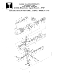
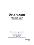
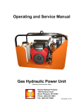
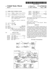
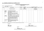
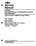
() Operating and Service Manual Rail Puller (Reference Serial Number Decal) ( ' ) Racine Railroad Products 1524 Frederick Street Racine, WI 53404-7577 Phone: (262) 637 - 9681 Fax: (262) 637 - 9069 910093-M Rev1 Draft 21 Jan 03.doc Table of Contents / ( .I Cover Page Record of Changes Table of Contents List of Figures & Tables Section 1 General Information and OvervIew 1.1 Purpose 1.2 Cancellation 1.3 Scope , , 1.4 Definitions 1.5 General Safety Precautions and Devices 1.6 Machine Description and Specifications 1.7 Machine Identification: 1.8 Machine Components and Major Assemblies Operator Controls .. ," 1.9 Service Manuals and Tools 1.11 Warranty Terms and Conditions Section 2 Initial Set-up and Adjustment 2.1 Inspection and Warranty Registration 2.2 Initial Assembly and In-Service Maintenance 2.3 Setup and Adjustments Section 3 Operating Procedures 3.1 Safety Precautions and Devices 3.2 Transportation & Handling...... . 3.3 Normal Operating Parameters 34 Emergency Procedures... . Section 4 Maintenance Procedures 3.5 Safety Precautions and Devices 3.6 Daily Inspection and Lubncation 3.7 Trouble Shooting Section 4 Parts Lists and Illustrations 4.1 Recommended Spare Parts List 4.2 Standard Parts List 4.3 Customer Options Lists by Serial Number Section 5 Parts and Service Support 5.1 Non-Warranty Parts Sales 5.2 Technical Support & Service 5.3 Warranty Parts & Service Section 6 Appendices 6.1 Sales Representatives 6.2 ii i ii iv '" , '" 1-1 1-1 1-1 1-1 1-1 1-1 1-2 1-6 1-6 1-7 1-10 1-10 2-1 2-1 2-1 2-3 3-4 3-4 3-4 3-5 3-6 3-6 3-6 3-7 3-8 4-1 4-1 4-1 4-2 5-1 5-1 5-1 5-2 6-1 6-1 6-1 i910093-M Rev1 Draft 21 Jan 03.doc This list identifies where photos, tables and other figures are located within the text of this manual. parts lists and drawings are provided in Section 5. An Figures Figure 1 Figure 1 Figure 2 Figure 3 Figure 4 Figure 5 Figure 6 Figure 7 Figure 8 Figure 9 Figure 10 Figure 11 Figure 12 Figure 13 Figure 14 Table 1 1.1 Rail Rail Rail Rail Rail Rail Rail Rail Rail Rail Rail Rail Rail Rail Rail Rail Puller - Front Page Puller - Left Frontal View Puller - Right Franta' View , Puller - Rail Frame Showing Center Datum Puller - Manufacture(s Data Plate Puller - Hydraulic Controls Puller - Hydraulic Quick Couplers Puller - Hydraulic pressure Gauge Puller - Rail Gripper Cams On Working End Puller - Rail Gripper Cams On Stationary End Puller - Synchronized Rail Gripper Cams Puller - Caution Decal. Puller - Lifting Chain , Puller - Operating Instructions Decal. Puller - Hydraulic Oil Drain Hose Puller -Hydraulic Hose Recommendation , '" " '" , , , , , , , 1-1 ;2-3 ~.2-3 2-4 2-5 2-6 , .2-7 2-7 , '" '" , '" .. 2-8 2-8 '" 2-9 3-4 3-4 3-6 3-8 2-2 Purpose This manual provides general Instructions for operating and maintaining the Racine Rallroad Products Rail Puller. 1.2 Cancellation Not Applicable, Initial Release. Record subsequent changes made to this manual on page i. 1.3 Scope This Bulletin applies to all Racine Railroad Products Rail Puller power tool Reference Serial Number Decal. 1.4 Definitions This manual uses the following standard terms for clarity: 1.4.1 DANGER! An operating procedure, practice, or condition, etc., which WILL RESULT IN INJURY OR DEATH if not carefully observed or followed. 1.4.2 WARNINGl An operating procedure, practice, or condition, etc., which may result in injury or death if not carefully observed or followed. 1.4.3 Caution! An operating procedure, practice, or condition, etc., which may result in damage to eqUipment if not carefully observed or followed. 1.4.4 Note: An essential operating procedure, practice, or condition, etc. 1.5 General Safety Precautions and Devices 2-1 i910093-M Rev1 Draft 21 Jan 03.doc WARNING! Failure to follow safety precautions when operating this equipment can result in serious injury or death to the operator or other persons in the area. Observe the following precautions whenever you are operating, working on or near this equipment. Always wear appropriate work clothing when operating this equipment. DO NOT WEAR loose clothing, jewelry, radio belts, etc., when you are operating, working on or near this equipment. 1.5.1 Always wear appropriate personal protective clothing when operating this equipment: (e.g. Orange safety vest, hard hat, safety glasses with side shields, full-face shield, hearing protection, steel-toed safety boots, leather gloves, dust respirator, leggings, etc.). 1.5.2 Always lift the Rail Puller with the 3-Point Lifting Sling and a truck crane or on-rail hoist. Always use care when transporting the Rail Puller and ensure proper footing and crew coordination when moving or positioning the Rail Puller. 1.5.3 This equipment may be operated from either side of the rail. Remove all spikes and anchors a minimum of 60 inches on both sides from the cut rail including ballast that may hinder the proper placing of the Rail Puller on the rail. 1.5.4 Keep your hands, arms, feet, head, clothing, etc., out of the operating area and away from all rotating or moving components when you are operating, working on or near this equipment. 1.5.5 Ensure that all guards. covers, hoses and operating components are in good working order and that all controls are in the appropriate position before starting the engine. Ensure that installed safety equipment (e.g. fire extinguishers, first aid kits, locking and safety devices) are installed properly and are in good working order. DO NOT OPERATE the machine until unsafe conditions have been corrected.. 1.5.6 Operate the POWER SOURCE ENGINE only in a well-ventilated area and ensure that the air filter(s), air filter cover(s), muffler are in good condition. DO NOT crank the engine with the spark plug removed. 1.5.7 Keep the machine clean and free of debris. Operate the machine in a safe and responsible manner. Exercise caution when working on or near rotating or moving components, hot components and fuel systems. Be aware of potential fire hazards and prevent sparks, etc., from starting fires on right-of way. 1.5.8 Comply with all instructions prOVided on any decals or placards installed on the machine and with any relevant amplifying information provided in this manual or other general operating procedures. 1.5.9 When you leave this equipment, even for a short time, shut off the hydraulic power source and disengage the hydraulic supply hoses. 1.5.10 Shut off the power source engine, ensure that all controls are in a safe position and install all appropriate locking and safety devices before doing any of the following: • • • • Lubricating Adjusting Making Repairs Performing Service 2-2 ,/' \ "\ j 1.5.11 1.6 Comply with all Lock Out / Tag Out Procedures and other safety procedures established for your work environment. Machine Description and Specifications The Racine Railroad Products Rail Puller is a transportable, remotely powered tool designed for rail welding joint tensioning. The Racine Rail Puller accommodates 115 lb. to 141 lb. rail and is positioned on work site using the 3-Point Lifting Sling and truck crane or hoist. Rail Puller: Left Frontal View Figure 2 Rail Puller: Right Frontal View. 2..3 910093-M Rev1 Draft 21 Jan 03.doc ( '" Figure 3 1,6.1 Rail Puller: Showing Center Datum Manufacturer: Racine Railroad Products, Inc. 1524 Frederick Street P.O. Box 044577 Racine, WI 53404-7577 Phone: (262) 637-9681 E-mail: [email protected] Website: http:\\www.racinerailroad.com 1.6.2 Physical Data: Tool Specifications: Hydraulic System: Open Center 108.00 in. (-274.3 cm) Length: 28.00 in. (-71.1 cm) Width: Height, Work Mode: 19.94 in. (-50.6 cm) 1130 Ib Weight: (less tools) (-512.5 kg) Temperature: Upper ambient operating 110 0 F (43 0 C) Lower ambient operating -20 F (-28 C) 0 2-4 0 0 ( Lower ambient operating -20 0 F (-28 C) ) Options and Accessories: Contact: Racine Railroad Products 1524 Frederick Street P.O. Box 044577 Racine, WI 53404-7577 Phone: (262) 637-9681 (262) 637-9669 Mechanical Data Open center Hydraulic Motor: 10 gpm Maximum Flow: ..2000 psi Maximum Pressure: Maximum Back Pressure: 250 psi Performance Data: (-40Ipm) (-138 bar) (- 14 bar) Production Rate: 1.7 Machine Identification: The Manufacturer's data plate is located on the control panel of the assembly. Please provide the Racine Railroad Products Model and Serial Number, and any locally assigned identification number, to our customer service personnel when contacting the factory for parts, service or warranty support. 910093 031436501 . . .~:::========== _=.==.__ ::=-----'='-' 46~463 Figure 4 Manufacturer's Data Plate 2.j.5 910093-M Rev1 Draft 21 Jan 03.doc ( \ ) 1.8 Machine Components and Major Assemblies 1.8. The Racine Railroad Products Rail Puller is comprised of a unitized main frame with the required components fastened onto. 1.9 Operator Controls Refer to Figures 5 through 10 to identify and locate the controls and major components of the Rail Puller Figure 5- Rail Puller: Hydraulic Controls 2-6 ( (~- Figure 6 Rail Puller: Hydraulic Quick Couplers Figure 7 Rail Puller: Hydraulic Pressure Gauge . \ 2+7 910093-M Rev1 Draft 21 Jan 03.doc / . \ ( ') Figure 8 Figure 9 Rail Puller: Rail Gripper Cams On Working End. Rail Puller: Gripper Cams On Stationary End. 2-8 / . \ INSPECT GRIPPER PADS FOR WEAR qR DAMAGE' .. DAILY(REPLACEIF'REQ'D) - Figure 10 1.10 I Rail Puller: Synchronized Rail Gripper Cams Service Manuals and Iools 1.10.1 Operating and Service Manuals: One Operating and Service Manual is provided with each machine. Manuals are shipped with each machine. 1.10.2 Operating and Service Manual Changes: The Operating and Service Manual may be updated to reflect product development and/or revised operating and maintenance procedures. If appropriate, Service Bulletins may be released to provide additional operational, maintenance and/or safety information. Record all changes made to this Manual in the Record of Changes on page i. Submit recommendations and requests for Operating and Service Manual Changes to: Racine Railroad Products, Inc. Attn: Technical Service Manager 1524 Frederick Street P.O. Box 044577 Racine, WI 53404-7577 Phone: (262) 637-9681 E-mail: [email protected] Website: http:\\www.racinerailroad.com 2.j.9 910093-M Rev1 Draft 21 Jan 03.doc 1.11 Warranty Terms and Conditions 1.11.1 Warranty Period: Each new machine, and new parts of our manufacture, are warranted against defects in material and workmanship for one year from the date of shipment from our factory. When contacting the factory for parts, service or warranty support, please provide the Racine Railroad Products Model and Serial Number and any locally assigned identification number to our customer service personnel to help them identify your machine and better serve you. 1.11.2 Vendor Parts Warranty Period: Other equipment and parts used, but not manufactured by Racine Railroad Products, Inc., are covered directly by the manufacturer's warranty for their products. 1.11.3 Warranty Parts and Service: We will repair or replace, without charge, F.O.B. factory, Racine, Wisconsin, USA, any part of our manufacture which is proven to be defective during the warranty period. Material claimed defective must be returned, if requested, to the factory within 30 days from the date of the claim for replacement. Ordinary wear and tear, abuse, misuse and neglect are not covered by this warranty. Depending upon the circumstances, we may provide technical assistance and/or technical service support. without charge, to assist in the correction of warranty related problem. 1.11.4 Non-Warranty Parts and Service: Material damaged through normal wear and tear, abuse, misuse and/or neglect are not covered by this warranty_ Non-Warranty Parts and Technical Service policies and procedures are prOVided in Section 6 of this manual. 2-10 / ,'" /' Section 2 2.1 Initial Set-up and Adjustment Inspection and Warranty Registration The Rail Puller is normally shipped via common carrier in a crate or pallet. The warranty period begins on the date of shipment from our factory. Upon delivery by the carrier, inspect the Rail Puller and shipping materials for damage. Ensure that all items indicated on the packing list have been received. Address items lost or damaged in shipment with the freight carrier. 2.1.1 Removing Packing Materials / Delivery Inspection: Remove the packing materials and inventory the contents of the packing list. Ensure that Operating and Service Manuals, tool kits and any other materials sent with the machine are in good condition. 2.1.2 Product Registration Card: Please fill out and return the Product Registration Card to help us better serve you. Your feedback on the Product Registration Card helps us improve our products and service. Note: Unless otherwise indicated, the address and contact name provided on the Product Registration Card will be the mailing address for future Service Bulletins and Customer Service Information. Note: Please contact our Service Department at the address provided in Section 6 of this manual if you have any problems with or questions about your new machine. 2.2 Initial Assembly and In-Service Maintenance The Rail Puller was tested after assembly at our factory. Flammable liqUids were removed for shipping and must be reinstalled. After assembly, the machine should receive a thorough In-Service inspection before initial operation. If you do not feel qualified to perform this In Service work yourself, contact a competent mechanic or the Racine Railroad Products Service Department for technical support. 2.2.1 Uncrating a new machine: Support the Rail Puller and cut the banding (if any)to release the machine from the shipping crate. Use the included 3-point lifting sling and a truck crane or hoist to lift the Rail Puller. The lifting sling points and the lifting sling (cha,in assembly with 3 hooks) are color coded with a red donut decal-sling point located on the stationary end of the Rail Puller is for the red colored single sling hook a,nd two blue donut decal-sling points on the work end of the Rail Puller accommodate the two blue colored sling hooks. Remove Rail Puller, options and accessories separately clear of the crate and place on a safe surface. 2.2.2 Initial Assembly: After unpacking and inspecting the Rail Puller ,options and accessories prepare the unit for service by doing the following: Hydraulic Systems: Use a calibrated flow meter and pressure gauge to check the hydraulic power source for 5 -10 gpm/20-38 Ipm at 1500-2000 psi/100-138 bar. • Relief valves should be adjusted for a cracking pressure 2200-2300psi/152-159 bar with full flow pressure not exceeding 2500 psi/173 bar measured at the power supply outlet. • The hydraulic system's back pressure measured at the tool end of the return hose should not exceed 250 psi/17 bar when operating at the maximum system flow, 2-1 i910093-M Rev1 Draft 21 Jan 03.doc system conditions for measurements are at maximum fluid viscosity of 400 ssu (82 centistol<es) i.e. at minimum expected operating temperature. The recommended minimum cooling capacity to dissipate tool generated heat at a 40° F (22° C) difference between ambient temperature and oil temperature is 6 H.P.l4.8 K.W. (210° BTU/min.). Hydraulic systems should have an ideal filter of 10 micron to a maximum of 25 micron nominal filtration. Filter elements should be sized for two to three times system flow to prevent filter by pass under low temperature start up and to provide maximum dirt holding capacity. Hydraulic Hose and Fluid Requirements: • • HYDRAULIC HOSE RECOMMENDATION GPM ! FEET LPM I TO 50 19 TO 30 I 51 TO 100 19 TO 30 TO 15 5 TO 8 19 TO 30 ! I r ! 9 TO 12 34 TO 45 \ I 100 TO 300 TO 50 I 15 TO 30 : 30 TO 90 : 9 TO 12 : 34 TO 45 I 51 TO 100 I 9 TO 12 24 TO 45 ! MM BOTH 1/2 13 SAE 100R1-8 100R7-8 BOTH 5/8 16 SAE 100R2-10 SAE 100R8-10 16 19 SAE 100R2-10 SAE 100R1-12 SAE 100R8-1 0 SAE 100R7-12 16 SAE 100R2-1 0 SAE 100R8-10 SAE SAE SAE SAE SAE 100R8-1 0 SAE 100R7-12 SAE 100R8-12 SAE100R7-16 I PRESSURE I RETURN TO 15 15 TO 30 ' I 100 TO SAE SPEC HOSE (FIBER BRAID) INCH i BOTH 5/8 3/4 5/8 i i j I I SAE SPEC HOSE (WIRE BRAID) i ! ! INSIDE DIAMETER I METERS I I i 5TO 8 I I i 5 TO 8 USE LENGTH EACH HOSE FLOW PER CIRCUIT 30 TO 60 \ 200 PRESSURE RETURN PRESSURE RETURN I I I I 5/8 3/4 3/4 1 I I I i 16 19 19 25.4 100R2-1 0 100R3-12 100R2-12 100R1-16 NOTE: HYDRAULIC HOSE TYPES 1. LABELED AND CERTIFIED NON-CONDUCTIVE TO BE USED NEAR ELECTRICAL CONDUCTORS. 2. WIRE BRAIDED (CONDUCTIVE): DO NOT USE NEAR ELECTRICAL CONDUCTORS. 3. FABRIC BRAIDED (NOT CERTIFIED OR LABELED NON-CONDUCTIVE): DO NOT USE NEAR ELECTRICAL CONDUCTORS. 4. HYDRAULIC HOSE RATED WORKING PRESSURE MUST BE AT LEAST 2500 PSI/173 BAR. 5. RECOMMENDED HOSE SIZE: .500 INCH/12mm 1.0. UP TO 50 FT.J15 M LONG. 6. RECOMMENDED HOSE SIZE: .625INCH/16 mm 1.0. UP TO 100 FT.J30 M LONG. VISCOSITY (FLUID THICKNESS) U.S.A. 50° F 450 SSU Max. 100° F 130-200 SSU 140° F 85 SSU Min. METRIC 10° C 95 Centistokes 38° C 27-42 C.S. 60° C 16.5 C.S., Min. Pour Point 10° F/23° C Minimum (for cold startup) Viscosity Index (ASTM 0 2220) 140° F Minimum Oemulsibility (ASTM 0-1401) 30 Minutes Maximum Flash Point (ASTM 0-92) 340 0 F/171° C Minimum Rust Inhibition (ASTM 0-665 A & B) Pass Oxidation (ASTM 0943) 1000 Hours Minimum Pump Wear Test (ASTM D2882) 60 mg Maximum 2-2 • • • • • • • • • • • • 2.3 The Racine Hydraulic 910098 power unit is recommended for hydraulic supply. This unit is equipped with two 5 gpm/20 Ipm circuits that can be combined for one 10 gpm/40 Ipm circuit. If the tool is used in cold weather, preheat the hydraulic fluid by running power source at low engine speed. Fluid temperature should be at or above 50° F/10° C (400 ssu/82 centistokes) before use, when using recommended fluids. Using too thick of 'fluid may result in tool damage. Check that the power is open-center system. Do not use the Rail Puller with closed center system or tool damage may occur. Check hydraulic hosed for cracks. leakage and damage. If the hoses or couplers show any of these wear characteristics, replace them before operating the tool. NEVER attempt to locate leaks with your hands, personal injury may occur 'from pressure system. Gripper Pads: Check gripper pads for wear or damage. Replace excessively worn or damaged pads before use. Gripper pads that are in poor condition can slip on rail. Check for loose or missing fasteners and roll pins. Replace or tighten any missing hardware before using Rail Puller. Hose Connecting Wipe quick couplers with a clean lint free cloth before connecting them. Connect hoses from power source to the tool. It is recommended that you connect the return hoses first and disconnect last to minimize or avoid trapping pressure within the tool. When connecting the qUick couplers. the flow should run from male coupler to female coupler. The female coupler on the tool IS the inlet. Quick couplers are marked with an arrow to show flow direction. Be sure the pressure hose is connected to the pressure port and the return hose connected to the return port. Note: When pOSSIble. connect the free ends of uncoupled hoses to prevent pressure build up in the hoses. The sun can also increase pressure in the hoses and make connecting difficult Turn on the hydraulic circuit at your power source. Note: Depending on temperature, let the power source and hydraulic oil warm up before applying full load. Setup and Adjustments • Tool Connecting Procedures The power unit should be off before connecting, or switching a tool and/or hoses. Turn the hydraUlic on/off valve to the off position before starting the engine. Make sure all hoses are connected for correct flow direction to and from the tool being used. When routing hose in the worl< area, position them where personnel will not be at risk of tripping over them or where vehicles can run over them. Also do not lay hose over sharp objects. Caution! DO NOT PULL ON HOSES TO DRAG THE POWER UNIT! • All mechanical and hydraUlic components are protected by shields or guards to assure long life of components and provide protection to the operator. All operations are self contained and automatic. No manual clamping or wedges are used with the Racine Railroad Products Rail Puller. Single control panel houses all controls and monitoring devices required to operate the unit. A single control is used to clamp the rail and pull the rail. A holding valve maintains the rail position and allows the hoses to be disconnected from the Rail Puller and used to operate other tools while welding. • 2+3 910093-M Rev1 Draft 21 Jan 03.doc ( Section 3 3.1 Operating Procedures Safety Precautions and Devices Before operating the Rail Puller perform a daily inspection of the tool as described in Section 4.2. Ensure that all general safety precautions are observed and that proper personal protective clothing is worn as described below. Personal Protective Equipment: The following Personal Protective Equipment should be worn by the operator. • • • • • • Figure 11 3.2 Safety Glasses Hearing Protection Safety Helmet High Visibility Safety Vest Leather Work Gloves Steel Toed Safety Shoes Rail Puller Caution Decal Transportation & Handling DANGER! NEVER ALLOW PERSONNEL BENEATH THE RAIL PULLER WHEN SUSPENDED. INJURY OR DEATH WILL RESULT IF RAIL PULLER IS LOWERED OR DROPPED ON PERSONNEL. ALWAYS STAND CLEAR AND MAINTAIN FIRM FOOTING WHEN GUIDING RAIL PULLER IN PLACE. The Rail Puller is typically transported by truck or rail. At job or storage site, the Rail Puller is lifted into position with the aid of a hoist or truck crane using the supplied three hook lifting chain sling vs. sling point locations (color coded to match the lifting sling hooks). The lifting chain sling's three point system levels and stabilizes the unit for easy positioning on the rail. Figure 12 Rail Puller Lifting Chain-Sling 3-4 3.3 Normal Operating Parameters Performance Data: The Racine Railroad Products Rail Puller is designed to pull two lengths of rail together in preparation for thermite and boutet welds. It will pull 120 tons and 6 inches of travel and will accommodate rail size ranging from 115 to 141 Ibs. The unit operates on low-pressure 2,000 psi/138 bar so a pressure intensifier is not used on this Rail Puller Production Rate: The Racine Railroad Products Rail Puller production rate is predicated on a need to use basis in railway maintenance activity. Caution! REMOVE RAIL SPIKES AND ANCHORS AT A MINUMUM CLEARANCE OF 60 INCHES ON EACH SIDE OF THE CUT RAIL JOINT TO BE WELDED BEFORE SETTING RAIL PULLER ONTO RAIL. Caution! DO NOT OPERATE RAIL PULLER WHEN BYSTANDERS ARE NEAR THE WORK AREA. Caution! DO NOT OPERATE RAIL PULLER NEAR FLAMMABLE MATERIALS OR ENERGIZED TRANSMISSION LINES. Caution! AVOID ENVIRONMENTAL OIL SPILLAGE. DISPOSE OIL DRAINED FROM TRAPPED PRESSURE VALVE IN A SUITABLE CONTAINER. Caution! DO NOT USE HOSES, COUPLERS OR FITTINGS WHICH ARE DAMAGED, REPLACE IMMEDIATELY. Caution' DO NOT DISENGAGE TENSION DURING RAIL JOINT WELDING OPERATION, ALLOW WELD TO COOL DOWN BELOW 700 0 F BEFORE RELEASING~ • • • • • • Securely connect the return (tank) hose first from the power source (port "T") to the tool ("Return port) and disconnect last to minimize or avoid trapping pressure within the tool. Securely connect the supply (pressure) hose secondly from the power source (port "P") to the tool ("Pressure" port). All mechanical and hydraulic components are protected by shields or guards to assure long life of components and provide protection to the operator. All operations are self-contained and automatic. No manual clamping or wedges are used with the Racine Railroad Products Rail Puller. Single control panel houses all the controls and monitoring devices required to operate the unit. A single control is used to clamp and pull the rail. A holding valve maintains the rail position and allows the hoses to be disconnected from the Rail Puller and used to operate other tools while welding. System pressure gauges and tons conversion legend along with cylinder positioning gauge allows the operator to monitor system functions while making a pull. Clear rail of spikes and anchors 60 inches on each side of joint cut. Use truck crane to lift and position Rail Puller on rail to be welded. Rail must set into opening on each end of the Rail Puller. Align center of opening in the rail with the "Center" decals on the Rail Puller frame. When the Rail Puller is properly positioned, unhook the lifting sling and remove sling from the work area. Operation Before operating the Rail Puller check that all guards are in position and securely fastened, and are in good condition. Inspect for any hydraulic oil leaks and repair as required. Do not operate the Rail Puller if a leak is present since the ability to hold the rail in position maybe lost if a leak reduces oil pressure. Close the trapped pressure valve completely. Turn the rail holding valve counterclockwise (release rail direction) to open the hydraulic circuit. 3+5 910093-M Rev1 Draft 21 Jan 03.doc • Inspect the gripper pads for wear or damage. Replace excessive worn or damaged pads before use. Gripper pads that are in poor condition can slip on rail. Inspect hoses, which connect the Rail Puller to power source for wear, cracking, fatigue or leaks before using. DANGER! NEVER INSPECT PRESSURIZED HOSES, COUPLERS OR FITTINGS WITH HANDS OR AT CLOSE DISTANCES. PRESSURIZED FLUID CAN PUNCTURE THE SKIN AND INJECT OIL INTO THE BODY WHICH WILL RESULT IN INJURY OR DEATH !! • • TO SAFELY TRANSPORT AND STORE THE RAIL PULLER PERFORM A NORMAL SHUT DOWN AS FOLLOWS. 1. Stop the hydraulic power source. 2. Depressurized the system. 3. Allow system and hydraUlic fluid to cool. 4. Disconnect the supply (pressure) hose to the power source (pressure port) from the tool. 5. Disconnect the return (tank) hose to the hydraulic power source ("Return" port) from the tool ("Out" port). 6. To prevent contamination, always install dust caps over the hydraulic ports of the . tool when disconnected. Prepare the unit for transport as outlined in above section. 3.4 Emergency Procedures In the event of any malfunction. IMMEDIATELY SHUT-OFF THE HYDRAULIC POWER SOURCE and correct the problem. WARNING! DO NOT PERFORM MAINTENANCE ON THE RAIL PULLER WHILE THE HYDRAULIC POWER SOURCE MOTOR IS RUNNING OR HOSES ARE CONNECTED!! 3.4.1 Maintenance Procedures 3.4.2 Safety Precautions and Devices Normal maintenance of the Rail Puller can be performed without any special maintenance related safety devices. Before operating the Rail Puller, perform a daily inspection as described in Section 4.2. Ensure that all general safety precautions are observed and that proper personal protective clothing is worn as described in Sections 1.5 and 3.1. WARNING! DO NOT PERFORM MAINTENANCE ON THE RAIL PULLER WHILE THE HYDRAULIC POWER SOURCE MOTOR IS RUNNING OR HOSES ARE CONNECTED!! 3.4.3 Safety Devices: Upon completion of maintenance, ensure that the following Safety Devices are installed on the Rail Puller: • • • • The hydraulic control valves are operable. The hydraulic quick couplers and hoses are safe to use. Weekly lubrication of the gripper cams and gripper arms. The gripper pads are in good condition. 3.4.4 Annually: Remove the cover from the opposite end as well as the control panel backside cover. Peform a detailed inspection of the systems hoses and fittings for damage and leaks. 3-6 ( • ') 3.4.5 No Special Procedures Required, See Local Requirements. . Figure 13 Rail Puller: Operating Instructions Decal • 3.5 Daily Inspection and Lubrication At a minimum, perform the following routine daily maintenance on the Rail Puller to keep it in good working condition. 3.5.1 Daily Inspection: Before operating the Rail Puller, inspect the following and correct any problems as necessary: • • • • • General Condition of the Assembly. All Guards and Safety Devices are Installed and Operable. All Controls are Operable. Hose Condition Routine Adjustments and Maintenance This section outlines basic adjustments and maintenance required for daily operation of the Rail Puller. These instructions are intended for operator level, field maintenance and not repair shop or overhaul level procedures. Lubricant Type and Locations: Use lithium complex NLGI #2 grease and apply 3-5 strokes to the gripper arms on a weekly basis. ( . \ \. 3+7 910093-M Rev1 Draft 21 Jan 03.doc ( ') Figure-14 3.6 Rail Puller: Hydraulic Oil Drain Hose. Trouble Shooting The following chart can be used as guide to correct any problems you may be experiencing with the Rail Puller. To determine the problem in operation of the Rail Puller, always check that the hydraulic power source is supplying the correct hydraulic flow and pressure to the tool as required in the Pre operation section of this manual. Be sure you are using an accurate flow-meter. Check the flow with the hydraulic fluid temperature at least 80° F/27° C. Always thoroughly check the power source and hoses before disassembling the Rail Puller. To determine the problem in operation of the Rail Puller, always check that the hydraUlic power source is supplying the correct hydraulic flow and pressure to the tool as required in the Pre-operation section of this manual. Be sure you are using an accurate flow-meter. Check the flow with hydraulic fluid temperature at least 80° F/2r C. Always thoroughly check the power source and hoses before disassembling the Rail Puller. Problem Unable to connect hydraulic hoses to Rail Puller. Rail Puller will not set down on rail. Possible Cause Remedy Pressure trapped in Rail Puller hydraulic systems. Open trapped pressure valve and lift control lever up while connecting hoses. Damaged couplers Inspect couplers replace if required Wrong size rail Rail Puller designed to fit 115 141 Ib rail Cams or gripper arm are closed Inspect cams and or gripper arms, fully retract Rail Puller so clamping systems opens. ( 3-8 Rail Puller clamping system does not move.. Rail Puller clamps Rail but does not have enough power to pull rail. \ Problem Rail Puller will not unclamp from rail Gap in rail does not close enough. Rail Puller slips on rail. i Rail holding valve is closed. Open rail holding valve Trapped pressure valve open. Closed trapped pressure valve. Hydraulic Flow not turned liON" at power source. Turn flow "ON" at power source Damaged hose in hydraulic system. Check for leaks and replace damaged hose. Contaminated relief valve on Rail Puller Have relief valve checked by qualified technicians. Trapped pressure valve open. Close trapped pressure valve. Damaged hose in hydraulic system. Check for leaks and replace damaged hose. Low setting or contaminated relief valve on power source.. Test power source and make repairs as required. Contaminated relief valve on Rail Puller. Have relief valve checked by a qualified technician. Possible Cause Remedy Rail holding valve is closed Open rail holding valve. Excess pressure on Rail Puller from Rail. Quickly switch control lever between pull and release. Rail Puller is at max pull Release rail and retract Rail Puller to llFully retracted" position. Try pulling rail again. Maximum pulling pressure has been achieved. Check the hydraulic system pressure gauge and determine the ton rate from legend. If reading indicates 120 tons rail has achieved maximum pulling pressure. Relief valve set too low at power source. Check pressure gauge reading on Rail Puller. Relief valve defective in Rail Puller. Irregular surface on rail where grippers grab. Test Rail Puller relief valve and repair as required. Inspect rail and reposition Rail Puller if required. Worn or damaged gripper pads.. Inspect gripper pads and replce as required. 3+9 910093-M Rev1 Draft 21 Jan 03.doc \ i 3.10 Special Tools: None specified 3-10 Parts Lists and Illustrations Section 4 The following parts lists are sorted by description, in alphabetical order, and grouped by the assembly that the individual parts are used on. The lists provide the part description, quantity used I required and part number for each part, as well as the part number of the assembly that the part is used on. A "List" in the "Dwg" column indicates that a parts list for the assembly is included in Sections 4.2 or 4.3 of this manual. A "Dwg" in the "Dwg" column indicates that a drawing of the part (with parts list) is included in Section 5.4 of this manual. Section Section Section Section 4.1 4.1 4.2 4.3 4.4 Recommended Spare Parts List Standard Parts List Customer Options Parts List List of Illustrations Recommended Spare Parts List The following parts are commonly used consumable, wear and I or routine maintenance items. We recommend that these parts be stocked in the quantities indicated below to maintain your machine at peak performance. Rail Puller Recommended Spare Parts List Description Qty Part No. Item No. Used on 910093 - 4.2 Standard Parts List This list includes all serviceable parts used on a standard model machine that has no customer options installed. See Section 4.3 for parts used on optional features that are added to the standard model. Rail Puller Description 4-1 PIN: 910093 Qty Part # Item No. Used On i910093-M Rev1 Draft 21 Jan 03.doc Qty Description PLATE, SERIAL NUMBER DECAL. LOGO 4.3 910093 PIN: Placard List, Rail Puller Part # Used On 1 1 Customer Options Lists by Serial Number These lists include all parts that are specified as customer options and not included in a base-model. These lists are sorted by customer / option. RRP Part No: 910093 RRP Sere No: RP - 001 - 03 I Customer Options Parts List II i ! Description Qty STANDARD MODEL: NOT APPLICABLE 4-2 Part No. Dwg Used on Parts and Service Support Section 5 5.1 Non-Warranty Parts Sales Material damaged through normal wear and tear, abuse, misuse and/or neglect are not covered by our warranty and should be ordered directly from our Customer Service Department. Parts for models that are no longer in production may not be available. 5.1.1 Parts & Customer Service Address: Please contact us at the following address for parts and customer service support: Racine Railroad Products. Inc. Attn: Customer Service 1524 Frederick Street P.O. Box 044577 Racine, WI 53404-7577 Phone: E-mail: Website: 5.1.2 262-637-9681 Extension: 105 custserv@raci nera iIroa d. co m http:\\www.racinerailroad.com Non-Warranty Parts Orders: When placing a parts order please provide the following information: • • • • • • • Company Name and Billing Address Purchase Order Number and Issuing Authority Shipping Address Special Handling Instructions Contact Phone Number Machine Model and Serial Number Part Numbers and Quantities Being Ordered Note: Please use Racine Railroad Products part numbers when ordering parts. Racine Railroad Products part numbers are shown on the parts lists and drawings in Section 5 of this manual and have only six (6) numbers. Any part number with other than six numbers (e.g. contains alpha-numeric characters) is a Vendor Part Number and NOT a Racine Railroad Products part number. 5.2 Technical Support & Service Telephone and web-based technical support is available for current production models through our Technical Service Department. Service Manuals and limited technical support may be available for models that are no longer in production. In the future, Technical Support features will be expanded on our home page on the world-wide-web. 5.2.1 Telephone and E-mail Technical Support: Telephone and E-mail technical support is available on normal U.S. business days from 8:00 AM to 5:00 PM U.S. Central Time Zone (GMT +6 (+5 Daylight Savings Time)). Contact us at: Phone: E-mail: Website: (262) 637-9681 Extension: 111 [email protected] http:\\www.racinerailroad.com 5-1 i910093-M Rev1 Draft 21 Jan 03.doc 5.2.2 Non-Warranty Technical/Field Service Support: Depending upon the circumstances and availability of technical service personnel, we may provide technical assistance and/or field service support, at the customer's expense, to assist in the correction of non warranty related problems. Contact our Technical Service Department to coordinate Non-Warranty Technical/Field Service Support. 5.2.3 Warranty Technical/Field Service Support: Depending upon the circumstances and availability of technical service personnel, we may provide technical assistance and/or field service support, at no charge to the customer, to assist in the correction of warranty related problems.. Contact our Technical Service Department to coordinate Warranty Technical/Field Service Support. 5.3 Warranty Parts & Service Warranty parts and service are coordinated through our Technical Service Department. Our warranty terms and procedures are provided in Section 1.11 of this manual. 5.3.1 Warranty Parts Claims: Material claimed to be defective must be returned to our factory for evaluation. Defective materials will be replaced, or your account will be credited if replacement materials have already been purchased. Please contact our Technical Service Department at the address provided below if you have any questions or problems. 5.3.2 Warranty Service Support: Depending upon the circumstances and availability of technical service personnel. we may provide technical assistance and/or field service support, at no charge to the customer. to assist in the correction of warranty related problems. Contact our TechnIcal Service Department at the address provided below to coordinate Warranty Technical/Field Service Support. Racine Railroad Products, Inc. Attn: Technical Service Manager 1524 Frederick Street P.O. Box 044577 Racine, WI 53404-7577 Phone: E-mail: Website: (262) 637-9681 Extension: 111 [email protected] http:\\www.racinerailroad.com 5-2 Section 6 6.1 Appendices Sales Representatives For more information about this. or any of our other products, please contact the nearest Representative shown on our Sales Representatives List. 6.2 The Owner's Manuals provided was current at the time of printing. 6-1 910093-M Rev1 Draft 21 Jan 03.doc RACINE RAILROAD PRODUCTS 1524 FREDERICK STREET RACINE, WI 53404 (262) 637-9681 910093-M RAIL PULLER ASSEMBLY RAIL PULLER ASSEMBLY BILL OF MATERIAL. (CAUTION USE ONLY GENUINE RACINE RAILROAD PRODUCTS, INC. PARTS. THE SUBSTITUTION OF REPLACEMENT PARTS WHICH ARE NOT OF EQUIVALENT QUALITY MAY DAMAGE THE HYDRAULIC RAIL PULLER). ITEM No. 1. 2. 3. 4. 5. 6. 7. 8. 9. 1O. 11. 12. 13. 14. 15. 16. 17. 18. 19. 20. 21. 22. 23. 24. 25. 26. 27. 28. 29. 30. 31. 32. 33. 34. 35. 36. 37.-_ _ 38. 39. 40. 41. PART No. DESCRIPTION NUT, .375"NC HH PLATED NUT, .25" NC HH PLATED LOCK WASHER .375" LOCK WASHER .25" WASHER, FLAT .50" PLATED .WINGNUT, .25" NC NUT, .50" NC HH SELF LOCKING BOLT, .50" NC X 2.75" PL HH GR.5 BOLT, .32" NC X 1.25" SHCS BOLT, .50" NC X 1.25" HH PL GR.5 BOLT, .25" NC X 1.0" HH PL GR. 5 BOLT, .25" NC X 5.0" GRADE 8 FRAME, COMPLETE CARRIER, CAM COMPLETE CAM, COMPLETE (R) CAM, COMPLETE (L) ARM, GRIPPER (R) COMPLETE ARM, GRIPPER (L) COMPLETE HYD. CYLINDER WELDMENT (R) HYD. CYLINDER WELDMENT (L) GUIDE CYLINDER END COMPLETE PANEL, STATIONARY END COMPo PANEL, CONTROL COMPLETE PANEL COVER (CONTROL) COMPo CYLINDER, SLAVE COMPLETE GEAR, TIMING COMPLETE (R) GEAR, TIMING COMPLETE (L) PLATE, RETAINING GUARD, CYLINDER BOLT GUARD, GAUGE FLAP, SPARK LINK, GRIPPER ARM ADAPTER, LINK/CYLINDER PIN, GRIPPER ARM ZERK,GREASE TUBE, CYLINDER lo 1057 --__.. ROD, CYLINDER RIVET, POP SD46BS .25" X .375" FLAT WASHER, SAE No.6 NUT, .32" NC NYLOCK BOLT, .32" NC X4" (CYL. MOUNT) 4 QUANTITY 3 4 11 2 4 2 2 2 6 4 2 4 1 1 1 1 1 1 1 1 2 2 1 1 2 1 1 2 2 1 1 2 1 2 2 1 1 14 14 4 4 RACINE RAILROAD PRODUCTS 1524 FREDERICK STREET RACINE, WI 53404 (262) 637-9681 i~~J '-- __ 910093-M RAIL PULLER ASSEMBLY RAIL PULLER ASSEMBLY BILL OF MATERIAL ITEM No. 42. PART No. 43. 44. 45. 46. 47. 48. 49. 50. 51. 52. 53. 54. 55. 56. 57. 58.4-tl105B - - 5 9 . - ~HD10sq - ", DESCRIPTION PIN, COTTER .125" X 1.25" BOLT, 375" NC X 2.5" SHCS PLATED BOLT, .375" NC X 1.0" HH PL GR.5 BOLT, .375" NC X 12" CARRIAGE BOLT, .25" NC X .50" SSBHCS SCREW, SOCKET SET .25"-20 X .375" NUT, JAM BOLT, .50" NC X 2.0" HH PL GR.5 QUANTITY 3 8 6 1 13 1 12 1 WASHER, .25" FLAT PLATED .25" X .75" STAINLESS STEEL WEAR PAD @ CYLINDER SCREW, SET10-32 NF x .375" 1 8 1 12 CAP WASHER, FLAT .187"BLK ZINC SPRING, CAM RETURN GRIPPER PAD 1 .' 2 1 2 4 RACINE RAILROAD PRODUCTS 1524 FREDERICK STREET RACINE, WI 53404 (262) 637-9681 / /' 910093-M RAIL PULLER ASSEMBLY "-\ CAM ARMS ACTUATOR CYLINDER ASSEMBLY BILL OF MATERIAL. ITEM No. 1. 2. 3. 4. 5. 6. 7. 8. 9. 10. 11. 12. 13. PART No. DESCRIPTION PISTON, CYLINDER BACKUP PISTON O-RING, PISTON BOLT, .375" X 1.00" SHCS O-RING O-RING END CAP, ROD SEAL, WIPER WIPER SEAL ROD SEAL, ROD BACKUP, ROD TUBE, CYLINDER ROD, CYLINDER QUANTITY 1 2 1 1 1 2 1 1 1 1 1 1 1 II 1 RACINE RAILROAD PRODUCTS 1524 FREDERICK STREET RACINE, WI 53404 (262) 637-9681 \ ) "---- 910093-M RAIL PULLER ASSEMBLY RIGHT BASE CYLINDER ASSEMBLY BILL OF MATERIAL. ITEM No. 1. 2. 3. 4. 5. 6. 7. 8. 9. 10. 11. 12. 13. 14. 15. 16. 17. PART No. DESCRIPTION GLAND, CYL. END COMPLETE PISTON, CYLINDER ROD, CYLINDER COMPLETE RING, RETAINING O-RING O-RING BACKUP RING O-RING WIPER SEAL ROD O-RING BACKUP RING RING, BACKUP HYDRAULIC CYLINDER (R) BOLT, .25" X 1.50" FSC BOLT, .32" NC X 1.25" SHCS RETAINING RING O-RING 1 QUANTITY 1 1 1 1 1 2 4 1 1 1 2 2 1 4 4 1 1 RACINE RAILROAD PRODUCTS 1524 FREDERICK STREET RACINE, WI 53404 (262) 637-9681 910093-M RAIL PULLER ASSEMBLY HYDRAULIC FITTINGS BILL OF MATERIAL. ITEM No. 1. PART No. 2. 3. 4. 5. 6. 7. 8. 9. 10. 11. 12. 13. 14. 15. 16. 17. 18. 19. 20. 21. 22. 23. 24. 25. 26. 27. 28. 29. 30. 31. 32. 33. 34. 4191Dlo I DESCRIPTION NUT, .25"NC HH PLATED LOCK WASHER, .25" NUT, .32" NC X 2" SHCS WASHER, FLAT,.25" PLATED BOLT, .32"NC X 2" SHCS LOCKWASHER, .32" PLATED BOLT, .25" NC X 1.75"HH PL GR.5 FITTING FITTING FITTING FITTING COVER, COUPLER COVER, COUPLER FITTING FITTING· FITTING FITTING COVER, COUPLER COVER, COUPLER FITTING FiniNG FITTING FITTING VALVE, NEEDLE FITTING, TEE MANIFOLD, HYD. RETURN FITTING,90° MANIFOLD, HYDRAULIC GAUGE, PRESSURE VALVE, CONTROL VALVE, HOLDING SPACER,NEEDLEVALVE FITTING, 90 0 FITTING, TEE &lbouJ 1 QUANTITY 2 2 2 2 2 2 2 6 3 1 1 1 1 1 1 1 1 1 1 1 1 1 1 1 1 1 1 1 1 1 1 1 2 1 RACINE RAILROAD PRODUCTS 1524 FREDERICK STREET RACINE, WI 53404 (262) 637-9681 910093-M RAIL PULLER ASSEMBLY EXPLODED VIEW OF RAIL PULLER ,\ ~l I I I I I I I I ---~( ! ~ 22 13 fib : lll'~.• ~ ~ RAIL PULLE~ VITH SERIAl' 021425012 AND UP RACINE RAILROAD PRODUCTS 1524 FREDERICK STREET RACINE, WI 53404 (262) 637-9681 C-) 910093-M RAIL PULLER ASSEMBLY --------- _._-_._---_._-_._-~._-_ EXPLODED VIEW OF HYDRAULIC FITIINGS CONNECTIONS ) \ (l ..... __ ._.- ---. 15 t » ) 4 RACINE RAILROAD PRODUCTS 1524 FREDERICK STREET RACINE, WI 53404 (262) 637-9681 910093-M RAIL PULLER ASSEMBLY HYDRAULIC HOSE ASSEMBLIES BILL OF MATERIAL. ITEM No. 1. 2. 3. 4. 5. 6. 7. 8. 9. 10. 11. 12. 13. 14 '- PART No. DESCRIPTION HOSE ASSY, HYD HOSE ASSY, HYD HOSE ASSY, HYD HOSE ASSY, HYD HOSE ASSY, HYD HOSE ASSY, HYD HOSE ASSY, HYD HOSE ASSY, HYD HOSE ASSY, HYD HOSE ASSY, HYD HOSE ASSY, HYD HOSE ASSY, HYD HOSE ASSY, HYD HOSE ASSY, HYD ' 1 QUANTITY 4 2 2 1 1 1 1 1 1 1 1 1 2 1