1
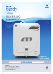
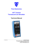
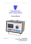
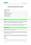
7007 Loop–Mate 2 Loop / Voltage / Current Simulator User Manual Time Electronics Ltd Unit 11 Botany Industrial Estate Tonbridge, Kent, TN9 1RH Tel: 01732 355993 Fax: 01732 770312 E-Mail: [email protected] Web Site: www.timeelectronics.co.uk V1.3b 28/08/07 7007 Loop-Mate 2 Manual Contents Page Introduction 1.1 General description 1.2 Specification 1.3 Front Panel Controls 2 3 4 Loop-Mate2 Operation 2.1 Function Select 2.11 Display Select 2.2 Description of typical process loop components 2.3 RxSim 2.4 TxTest 2.5 Meas Volts DC 5 5 5 7 8 9 Power Supply 3.1 Battery Life 3.2 Battery Replacement 10 10 Maintenance 4.1 Checking Calibration 4.2 Adjustment of Calibration 4.21 Disassembling Loop-Mate2 4.22 Trimmer Locations 4.23 Reference voltage check and adjustment 4.24 RxSim / TxTest calibration 4.25 Meas Volts DC calibration 4.26 Re-assembly 4.3 Fuse Replacement 11 15 15 16 17 18 18 19 20 Guarantee & Servicing 21 All Time Electronics instruments are subject to continuous development and improvement and in consequence may incorporate minor detail changes from the information contained herein. Page 1 7007 Loop-Mate 2 Manual 1. Introduction 1.1 General Description Loop-Mate2 is a dedicated loop signal indicator (RxSim); with an in-built 24v loop drive supply (TxTest). The operator can select the loop type, and also the type of units, either direct (mA) or % of span display. The loop signal is shown on an easy to read LCD display to an accuracy of 0.05% either in mA, V, or % of span. In addition to TxTest (transmitter test) and RxSim (receiver simulation) LoopMate2 can also be used to measure dc voltage in the process loop (Meas Volt DC) up to 50v. The Loop-Mate2 is powered by the universally available PP3 type battery. Rechargeable batteries can be used if required. Loop-Mate2 is a service and maintenance engineer’s best friend. It combines low cost and simple operation while providing more than enough accuracy for most applications. Used in conjunction with Loop-Mate1 they provide full process loop testing capabilities, facilitating quick location of faults, testing and recalibration. It comes complete with carrying pouch, leads, clips, and a user manual. Page 2 7007 Loop-Mate 2 Manual 1.2 Specification Functions: RxSim, TxTest, Meas Volt DC. Ranges: RxSim 0-50mA or 0%-100% (4-20mA) TxTest (RxSim plus Internal 24v dc loop drive supply) 0-25mA or 0%-100% (4-20mA), Meas Volt DC 0-50v dc or 0%-100% (0-10v). Accuracy: 0.05% of Span (% of span) and 0.05% of Range (mA/V) Indication: 4.5 digit LCD display. Connections: Two 4mm recessed sockets Power: PP3 battery Carrying Pouch: Leatherette material. Includes compartment. Leads: 4mm gold plated. Temperature co-efficient: The unit stays within specification over operating temperature range. Operating temp: 0 to 50 degC Storage temp: -30 to 70 degC Operating humid: 10 – 90% non-cond 25degC Dimensions / weight: 14 6.6 2.7cm (6 2.5 1in) / 280gm (10oz) Page 3 7007 Loop-Mate 2 Manual 1.3 Front Panel Controls 1) Connection Terminals (Recessed) 2) Display Switch 3) LCD Display 4) Function Switch Page 4 7007 Loop-Mate 2 Manual 2. Loop-Mate2 Operation 2.1 Function Select The Loop-Mate2 has 3 functions: Function 1: Function 2: Function 3: RxSIM TxTEST Meas Volt DC These are selected using the function select switch. 2.11 Display Select For RxSim and TxTest the signal can be displayed either direct (mA) or % of span. These are selected using the display select switch, which also turns off the LoopMate2. 2.2 Description of typical process loop components 4-20mA process loop 0-10v process loop 4-20mA Process loop and 4-20mA Control loop (Can be used for closed loop control) Page 5 7007 Loop-Mate 2 Manual Tx (transmitter): This component converts physical signals such as pressure, temperature, flow, and level etc, into the loop signals (4-20mA or 0-10v). Rx (receiver): This component measures the loop signal and either displays it (indicator) or converts it to another form e.g. digital output for control purposes, (controller). Process Controllers: This device usually contains both Rx (signal loop) and Tx (control loop) components, which operate in separate loops. The Rx and Tx can be either 4-20mA or 0-10v. Loop excitation supply: A DC power supply (nominally 24v) that drives the loop. Page 6 7007 Loop-Mate 2 Manual 2.3 RxSim function The unit displays the loop current in either mA (0-50mA) or percentage of span (420mA), depending on the position of the display select switch. Operation: Connect the unit to the process loop observing the correct polarity. Set the function switch to RxSim. Turn the unit on, selecting the desired display units, using the display switch. Note: If the loop current is less than 4mA, negative % of span will be displayed. See table below. Loop Current (mA) Open Circuit 1 2 3 4 Display Reading -25.00 -18.75 -12.50 - 06.25 00.00 RxSim +ve Loop-Mate2 Loop excitation supply Tx -ve (Transmitter) 4-20mA RxSim Connection Page 7 7007 Loop-Mate 2 Manual 2.4 TxTest function With TxTest selected, a loop excitation drive supply (24v) is internally generated. The display will show the loop current as either mA (0-50mA) or percentage of span (4-20mA), depending on the position of the display select switch. Operation: Connect the unit to the process loop observing the correct polarity. Set the function switch to TxTest. Turn the unit on, and select the desired display units, using the display switch. Note: If the loop current is less than 4mA, negative % of span will be displayed. See table below. Loop Current (mA) Open Circuit 1 2 3 4 Display Reading -25.00 -18.75 -12.50 - 06.25 00.00 TxTest Loop-Mate2 -ve +ve Tx (Transmitter) 4-20mA TxTest Connection Page 8 7007 Loop-Mate 2 Manual 2.5 Meas Volt DC function When the unit is set to Meas Volt DC it displays the voltage either as Volts (0-50v) or percentage of span (0-10v), depending on the position of the display select switch. Operation: Connect the unit to the process loop observing the correct polarity. Set the function switch to Meas Volt DC. Turn the unit on, selecting the desired display units, using the display switch. Meas Volts DC +ve Tx (Transmitter) 0-10v Loop-Mate2 -ve Voltage loop TxTest connection Note: The unit can be used to measure DC voltages up to a maximum of 50v DC. Page 9 7007 Loop-Mate 2 Manual 3. Power supply 3.1 Battery life A single PP3 battery powers the unit. Types that can be used are Zinc Carbon (250mAh), Alkaline (450mAh), Lithium (1200mAh) and rechargeable (150mAh). For best performance Lithium batteries are recommended. Under typical usage an Alkaline (450mA) battery will last for approximately 14 - 16 hours of continuous operation. Assuming the Loop-Mate2 is used for approximately 3 hours per day the batteries will last for a week or more. Continuous operation on the TxTest function will shorten the battery life. The unit will display ‘low battery’ when the battery voltage is too low. At this point replacement of the battery is necessary. It is recommended that a spare battery be always carried in the compartment provided in the carrying pouch. 3.11 Battery replacement Slide off the back cover of the case and remove the battery from its compartment. Unclip the battery and replace it with a new PP3 as shown below. Then slide the battery cover back into place. The pictures above show the removal of the battery. The reverse procedure should be used to replace the battery. Page 10 7007 Loop-Mate 2 Manual 4. Maintenance 4.1 Checking Calibration Calibration equipment required Precision dc current source e.g. Time Electronics 1024 Precision dc voltage source e.g. Time Electronics 5025 DMM with accuracy of 0.02% or better. Examples of suitable instruments are Time Electronics’ 5075, or HP 34401A. Calibration should be done at 20C 5 deg C. Checking Calibration (RxSim) Direct reading (mA) Connect the precision dc current source to the input terminals of the Loop-Mate2. Set the Function switch to RxSim. Set the Display switch to mA/V. Set the output of the dc current source to those shown (mA input to Loop-Mate2) in table 1 on the next page, and check the display reading is between the Min and Max values. Page 11 7007 Loop-Mate 2 Manual Table 1. mA input 10 20 30 40 50 Min value (mA) 9.975 19.975 29.975 39.975 49.975 Max value (mA) 10.025 20.025 30.025 40.025 50.025 Percentage of span With the Loop-Mate 2 open circuit, set the Function switch to RxSim. Set the Display switch to % of span. The display should read –25.00 0.01. Switch off the unit. Connect the precision dc current source to the input terminals of the Loop-Mate2. Set the Function switch to RxSim. Set the Display switch to % of span. Set the output of the dc current source to those shown (mA input to Loop-Mate2) in table 2 on the next page, and check the display reading is between the Min and Max values. Page 12 7007 Loop-Mate 2 Manual Table 2. % of span mA input 0 25 50 75 100 4 8 12 16 20 Min value (%) -0.05 24.95 49.95 74.95 99.95 Max value (%) 0.05 25.05 50.05 75.05 100.05 If the reading on the Loop-Mate2`s display is out of specification then adjustment of the calibration will be required (see later in this section). Checking Calibration (Meas Volt DC) Direct reading (volts) Connect the precision dc voltage source to the input terminals of the Loop-Mate2. Set the Function switch to Meas Volt DC. Set the Display switch to mA/V. Set the output of the dc voltage source to those shown (Volts input to Loop-Mate2) in table 3 below, and check the display reading is between the Min and Max values. Table 3. Volts input 0 10 20 30 40 50 Min value (V) -0.025 9.975 19.975 29.975 39.975 49.975 Max value (V) 0.025 10.025 20.025 30.025 40.025 50.025 Percentage of span Connect the precision dc voltage source to the input terminals of the Loop-Mate2. Set the Function switch to Meas Volt DC. Set the Display switch to % of span. Turn on the Loop-Mate2. Set the output of the dc voltage source to those shown (Volts input to Loop-Mate2) in table 4 below, and check the display reading is between the Min and Max values. Page 13 7007 Loop-Mate 2 Manual Table 4. % of span Volts input 0 25 50 75 100 0 2.50 5.00 7.50 10.00 Min value (%) -0.05 24.95 49.95 74.95 99.95 Max value (%) 0.05 25.05 50.05 75.05 100.05 If the reading on the Loop-Mate2`s display is out of specification then adjustment of the calibration will be required (see later in this section). Page 14 7007 Loop-Mate 2 Manual 4.2 Adjustment of Calibration When Loop-mate2 is found to be out of specification the procedures described in the following sections must be followed. 4.21 Disassembling Loop-Mate2 First remove the battery compartment cover and disconnect the battery, as shown in section 3.11 of this manual. Remove the 4 screws from the back of the case. Position the Loop-Mate2 so that the front panel is facing upwards. Carefully lift the case lid. Next reconnect the battery. Page 15 7007 Loop-Mate 2 Manual 4.22 Trimmer Locations (used for adjusting the calibration) VR6 - % of span (current) offset adjust VR5 – Direct reading voltage adjust VR4 - % of span voltage adjust VR3 Reference voltage adjust VR2 - Direct reading current adjust VR1 - % of span current adjust Page 16 7007 Loop-Mate 2 Manual 4.23 Reference voltage check and adjustment Set the function switch to RxSIM Set the Display switch to mA/v. Select the voltage scale on the DMM Connect a test lead from the DMM negative input to the Loop-Mate 2 minus (-) terminal Connect a test lead with a pointed probe to the DMM positive input. Place the pointed probe on the pad near to VR3 as shown in the picture, thus making contact with VR3`s middle pin. The reading should be 1v. Adjust VR3 until 1v is displayed on the DMM. Page 17 7007 Loop-Mate 2 Manual 4.24 RxSim / TxTest calibration By calibrating RxSIM, TxTest is also calibrated Direct reading (mA) Connect the precision dc current source to the input terminals of the Loop-Mate2. Set the Function switch to RxSim. Set the Display switch to mA/V. Set the output of the current source to 50mA dc. Adjust VR2 until the display reads 50.00 Percentage of span (%) Offset calibration Before connecting the Loop-Mate 2 to any test equipment, Set the Function switch to RxSim. Set the Display switch to % of span. The display should read –25.00, if not adjust VR6 until –25.00 0.01 is displayed. Connect the precision dc current source to the input terminals of the Loop-Mate2. Set the Function switch to RxSim. Set the Display switch to % of span. Set the output of the current source to 20mA dc. Adjust VR1 until the display reads 100.00 4.25 Meas Volt DC calibration Direct reading (volts) Connect the precision dc voltage source to the input terminals of the Loop-Mate2. Set the function switch to Meas Volt DC. Set the Display switch to Volts. Select 50v dc output on the precision voltage source. Adjust VR5 until the display reads 50.00. Page 18 7007 Loop-Mate 2 Manual Percentage of span Connect the precision dc voltage source to the input terminals of the Loop-Mate2. Set the function switch to Meas Volt DC. Set the Display switch to % of span. Select 10v dc output on the precision voltage source. Adjust VR4 until the display reads 100.00 Repeat the Direct reading and Percentage of span calibration procedures until neither require adjust. This is required due to some interaction between the scales. Page 19 7007 Loop-Mate 2 Manual 4.26 Re-assembly Disconnect the battery after re-calibration. Refit the lid and screw the four case screws into place. Replace the battery and battery compartment cover. See section 3.11. 4.3 Fuse Replacement The unit is fitted with a 100 mA fuse. If no readings are displayed when using the RxSIM or TxTest function when connected to a known working process loop, it is possible that the internal fuse has blown. To replace the fuse: First remove the battery compartment cover and disconnect the battery, as shown in section 3.11 of this manual. Remove the 4 screws from the back of the case. Position the Loop-Mate2 so that the front panel is facing upwards. Carefully lift the case lid. The fuse is located below and to the right of the Display switch as shown in the picture below. Fuse F1 100mA Rating Pull out the fuse and replace with one of the same value. Replace the case lid, and screw the four case screws into place. Page 20 7007 Loop-Mate 2 Manual 5. Guarantee & Servicing Guarantee Period The Loop-Mate2 is guaranteed against defects in materials and workmanship for a period of one year from its delivery to the customer. During this period we will, subject to the instrument not being damaged due to maltreatment or overload, repair or replace it free of charge apart from shipping costs. For repair under guarantee, the instrument serial number must always be quoted, together with details of the fault. The purchaser of the instrument must prepay all shipping charges. This guarantee is void if servicing or repair has been attempted by an unauthorized person or agent. Service and Calibration Routine servicing and recalibration of your instrument is an essential part in the life of any calibration instrument. This will ensure that your instrument is performing to its specifications. All repairs are made using high grade and often specialised components to ensure on-going accuracy and performance. Our quality control (ISO9001) ensures the work is undertaken to the highest standards. When an instrument is returned for repair any product enhancements, updates (hardware and software) will be done automatically. Returning Instruments It is preferable to contact Time Electronics or their authorized agent to discuss any special paperwork (customer declarations etc) and shipping requirements. Always include information about the service required and your company details including a contact name, address, phone number and email address. Remember to include the name of the person you spoke to about the return. When returning instruments, please ensure that they have been adequately packed, preferably in the original packing supplied. We will not accept responsibility for units returned damaged. Time Electronics Ltd Unit 11 Botany Industrial Estate Tonbridge, Kent, TN9 1RH Tel: 44 (0)1732 355993 Fax: 44 (0) 1732 770312 E-Mail: [email protected] Web Site: www.TimeElectronics.co.uk Page 21