1
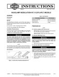
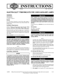
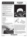
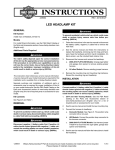
INSTALLATION INSTRUCTIONS
ATTENTION INSTALLER (if other than owner):
Please forward this instruction sheet to the purchaser
of this product. These instructions contain valuable
information necessary to the end user.
INTRODUCTION: These instructions describe the
procedure for properly installing replacement O-rings in
the fuel injection lines. Review instructions carefully before
beginning, as they contain important information. Please
retain for future reference.
DRAG SPECIALTIES
EFI FUEL LINE O-RING KIT
P/N 0706-0209
NOTE:
For fuel lines PART #s 0706-0121 & 0706-0125 use instruction
section “A” only.
For fuel lines PART #s 0706-0122 & 0706-0123 use instruction
sections “A” and “B”.
For fuel check valve assemblies 0706-0125, 0706-0126 and
0706-0128 use instruction section “C” only.
For fuel check valve assemblies 0706-0127, 0706-0129 and
0706-0130 use instruction sections “C” and “D”.
Instruction Section “A”
1. Remove the opposite end of the fuel line from the injector body NOTE: A NOTE provides key information to make
by removing the procedures easier or clearer.
retainer clip and bolt. The fuel line should be
CAUTION: A CAUTION indicates special procedures that
able to be removed must be followed to avoid damage to the motorcycle and/
from the bike at this time.
or accessories.
2. Place the fuel line on a sturdy flat surface, and WARNING!: A WARNING indicates special procedures
using a pin punch, push that must be followed to avoid injury to a motorcycle
down on the needle in the operator or person inspecting or repairing the motorcycle.
check valve (on the black end of the fuel line). Hold the check valve down in IMPORTANT! READ THIS SECTION FIRST!
this position.
NOTE: This kit includes 8 O-rings of differing sizes. It is very
3. Using a sharp pick,
important that you confirm that you are using the correct
remove the O-ring from
O-ring for the application as there are numerous O-rings
its groove in the fuel that are very close in size. All O-rings should be individually
line check valve body.
wrapped and marked “A” through “E” according to their
Pull the O-ring out.
application. There should be no duplication. Again, some are 4. Release the pressure on the check valve needle carefully as very similar in size, possibly only detectable by measuring
the needle and pressure spring can easily spring out and be
the O-rings. DO NOT MIX THEM UP! Review the chart at
lost. These parts are not available separately.
the end of these instructions to determine which O-rings are
5. Find the new O-ring marked “A”. This should be the smallest used on each particular fuel line.
O-ring in the kit.
6. Using the pin punch, press down on the check valve needle PROCEDURE:
until the spring is completely collapsed.
All models:
7. With the spring collapsed, insert the O-ring and using a thin 1. Disable the fuel pump by unplugging the connector going standard screw driver or other tool, push the new O-ring to the fuel pump at the gas tank, or by removing the fuse down until it is seated in its groove all the way around
that protects the fuel pump.
the housing.
2. Start the engine and run it until it dies. This will decrease 8. Release pressure on the check valve needle. The O-ring the pressure in the fuel lines so less fuel is spilled when the will retain the needle and cause it to seal.
lines are removed.
9. Install the fuel line back on the motorcycle. Installation is 3. Disconnect the negative battery cable and move it well
basically reverse of the removal process. Make sure that away from the battery negative post to prevent any the fitting on the hose is securely connected to the fitting sparking while working on the fuel system.
on the bottom of the tank. Also make sure there are no kinks in the hose.
WARNING!: Gasoline is extremely flammable. Use extreme
10. Reconnect the battery cables and reinstall the fuse
caution working on the fuel lines, as the gasoline will spill
if removed.
when removing the fuel lines. Do not work on the fuel
11. Turn on the ignition switch and listen to make sure the system with a hot engine. Prevent any random sparks from
fuel pump operates. Check the fittings on both ends of occurring by disconnecting the battery, negative cable first.
the fuel line to check for leaks.
Cleanup and dispose of any spilled gasoline immediately in
12. Test ride to ensure proper operation, and inspect again a proper manner.
for any leaks after the ride.
Particularly important information is distinguished in these
instructions by the following notations:
4. Remove the fuel line from the gas tank by pushing the chrome collar up firmly on the fuel tank outlet until the fuel line is released from the outlet. Expect that a small amount of gasoline should escape while removing
the fuel line.
REVISED 1/2014
3501 Kennedy Rd, PO Box 5222, Janesville, WI 53547-5222
P/N 0706-0209
Page 1 of 3
INSTALLATION INSTRUCTIONS
Instruction Section “B”
1. Remove the opposite end of the fuel line from the injector body by squeezing the two ends of the clip and sliding the clip to the
side to allow the line to
be removed from the
injector body fitting.
2. Squeeze the two ends
of the clip and remove
the clip from the
black housing.
3. Using a sharp pick, remove the O-ring from the groove inside the
black housing that was
connected on the
injector body.
4. Find the new O-ring marked “B” and insert it into the groove on the receptacle on the end of the fuel line. Using a thin standard screwdriver, or other similar tool, make sure the O-ring is seated securely.
Instruction Section “C”
1. Drain fuel from tank into an approved container and
set aside.
2. Disconnect the internal fuel line from the fuel pump/filter
assembly located inside the tank. Refer to the OEM service manual for details
on your particular model.
3. Carefully unscrew the chrome check valve from
the bottom of the tank and remove. Use caution as
there may be fuel remaining in the line or the bottom of the fuel tank.
4. Select the correct O-rings from the package. All models except the 0706-0125 for the 99-02 FLT/FLHT/FLHR will use three O-rings labelled “C”, “F” and “H”. The 0706-0125 for the 99-02 FLT/FLHT/
FLHR will use three O-rings labelled “C”, “F” and “G”. Do not remove the O-rings from their package until installation so they are not mixed up.
5. Remove the O-ring on the outside of the check valve in
the threaded area that is screwed into the bottom of the
fuel tank. Install either the “H” or “G” O-ring depending on the model application (see Step 4) making sure that the O-ring is not twisted when installed.
6. Using a sharp pick, remove the two O-rings from the inside of the check valve.
7. Find the new O-ring marked “C” and insert it into the farthest groove on the receptacle on the inside of the check valve. Using a thin standard screwdriver or other similar tool, make sure the O-ring is seated securely.
REVISED 1/2014
DRAG SPECIALTIES
EFI FUEL LINE O-RING KIT
P/N 0706-0209
5. Reinstall the clip back into the black housing, making sure the clip is slid to its furthest open position.
6. Install the fuel line back on the motorcycle. It works best to install the end onto the injector body, not forgetting to slide the clips back into the black housing to securely hold the fuel line onto the fitting.
7. Install the other end of the fuel line into the chrome check
valve fitting on the bottom of the fuel tank. Make sure there is no binding or kinks in the fuel line. The fuel line should seat with an audible click. Tug on the end of the fuel line to make sure it is fully seated.
8. Reconnect the battery cables and reinstall any fuses that were removed.
9. Turn on the ignition switch and watch closely for any fuel leaks. If any fuel is noticed leaking, immediately shut off switch and determine the cause of the leak. Repair or replace components as necessary.
10. Start engine and test ride. Upon completion of the test ride, please inspect the fuel line and fittings for any sign of fuel leakage.
8. Find the new O-ring marked “F” and insert it into the closest groove on the receptacle on the inside of the check valve. Using a thin standard screwdriver or other similar tool make sure the O-ring is seated securely.
9. Insert the internal fuel line back into the tank and screw the
check valve into the bottom of the tank. Tighten with a deepwell socket to 22-26 foot pounds.
10. Reconnect the fuel line to the filter/pump assembly in the tank per the instructions in the OEM service manual.
CAUTION: Do not attempt to unscrew or tighten the lower
check valve fitting with the hose attached to the filter/pump
assembly, as the internal hose will kink and cause premature
fuel line failure.
11. Reconnect the external fuel line to the check valve by
pushing up on the outer collar and pushing the fuel line
fitting into the check valve until you hear a “click”. Confirm that the fitting is locked into the check valve by tugging on the fuel line fitting.
12. Reconnect the battery cables and reinstall any fuses that were removed.
13. Turn on the ignition switch and watch closely for any fuel leaks. If any fuel is noticed leaking, immediately shut off switch and determine the cause of the leak. Repair or replace components as necessary.
14. Start engine and test ride. Upon completion of the test ride, please inspect the fuel line and fittings for any sign of fuel leakage.
3501 Kennedy Rd, PO Box 5222, Janesville, WI 53547-5222
P/N 0706-0209
Page 2 of 3
INSTALLATION INSTRUCTIONS
DRAG SPECIALTIES
EFI FUEL LINE O-RING KIT
P/N 0706-0209
Instruction Section “D”
7. Install either the “E” or “D” O-ring, depending on the model application (see Step 5) making sure that the O-ring is not twisted when installed.
8. Insert the internal fuel line back into the tank and screw the check valve into the bottom of the tank. Tighten with a deepwell socket to 22-26 foot pounds.
9. Reconnect the fuel line to the filter/pump assembly in the tank per the instructions in the OEM service manual.
CAUTION: Do not attempt to unscrew or tighten the lower
check valve fitting with the hose attached to the filter/pump
assembly, as the internal hose will kink and cause premature
internal fuel line failure.
10. Reconnect the external fuel line to the check valve by pushing up on the outer collar and pushing the fuel line
fitting into the check valve until you hear a “click”. Confirm that the fitting is locked into the check valve by tugging on the fuel line fitting.
11. Reconnect the battery cables and reinstall any fuses that were removed.
12. Turn on the ignition switch and watch closely for any fuel leaks. If any fuel is noticed leaking, immediately shut off switch and determine the cause of the leak. Repair or replace components as necessary.
13. Start engine and test ride. Upon completion of the test ride, please inspect the fuel line and fittings for any sign of fuel leakage.
1. Drain fuel from tank into an approved container and
set aside.
2. Disconnect the internal fuel line from the fuel pump/filter
assembly located inside the tank. Refer to the OEM service manual for details on your particular model.
3. Carefully unscrew the chrome check valve from the bottom of the tank and remove. Use caution as there may be fuel remaining in the line or the bottom of the fuel tank.
4. Using a sharp pick, remove the O-ring from the end of the fuel line opposite the chrome check valve.
5. Select the correct O-rings from the package, the 0706-0127 will use the O-ring marked “E”, the 0706-0129 and the
WARNING!: Before operating motorcycle, be sure all hardware
0706-0130 fuel lines will use the O-ring marked “D”.
is tight.
6. All other internal fuel lines do not have an O-ring seal at the fuel pump/filter location, but rather use a compression clamp to seal the fuel line connection.
REVISED 1/2014
3501 Kennedy Rd, PO Box 5222, Janesville, WI 53547-5222
P/N 0706-0209
Page 3 of 3